EP2814991B1 - Verfahren und anordnung zum vorschub-randschichthärten - Google Patents
Verfahren und anordnung zum vorschub-randschichthärten Download PDFInfo
- Publication number
- EP2814991B1 EP2814991B1 EP13704057.2A EP13704057A EP2814991B1 EP 2814991 B1 EP2814991 B1 EP 2814991B1 EP 13704057 A EP13704057 A EP 13704057A EP 2814991 B1 EP2814991 B1 EP 2814991B1
- Authority
- EP
- European Patent Office
- Prior art keywords
- marking
- workpiece
- hardening device
- hardening
- zone
- Prior art date
- Legal status (The legal status is an assumption and is not a legal conclusion. Google has not performed a legal analysis and makes no representation as to the accuracy of the status listed.)
- Active
Links
Images

Classifications
-
- C—CHEMISTRY; METALLURGY
- C21—METALLURGY OF IRON
- C21D—MODIFYING THE PHYSICAL STRUCTURE OF FERROUS METALS; GENERAL DEVICES FOR HEAT TREATMENT OF FERROUS OR NON-FERROUS METALS OR ALLOYS; MAKING METAL MALLEABLE, e.g. BY DECARBURISATION OR TEMPERING
- C21D1/00—General methods or devices for heat treatment, e.g. annealing, hardening, quenching or tempering
- C21D1/06—Surface hardening
- C21D1/09—Surface hardening by direct application of electrical or wave energy; by particle radiation
- C21D1/10—Surface hardening by direct application of electrical or wave energy; by particle radiation by electric induction
-
- C—CHEMISTRY; METALLURGY
- C21—METALLURGY OF IRON
- C21D—MODIFYING THE PHYSICAL STRUCTURE OF FERROUS METALS; GENERAL DEVICES FOR HEAT TREATMENT OF FERROUS OR NON-FERROUS METALS OR ALLOYS; MAKING METAL MALLEABLE, e.g. BY DECARBURISATION OR TEMPERING
- C21D11/00—Process control or regulation for heat treatments
-
- C—CHEMISTRY; METALLURGY
- C21—METALLURGY OF IRON
- C21D—MODIFYING THE PHYSICAL STRUCTURE OF FERROUS METALS; GENERAL DEVICES FOR HEAT TREATMENT OF FERROUS OR NON-FERROUS METALS OR ALLOYS; MAKING METAL MALLEABLE, e.g. BY DECARBURISATION OR TEMPERING
- C21D9/00—Heat treatment, e.g. annealing, hardening, quenching or tempering, adapted for particular articles; Furnaces therefor
- C21D9/0062—Heat-treating apparatus with a cooling or quenching zone
-
- C—CHEMISTRY; METALLURGY
- C21—METALLURGY OF IRON
- C21D—MODIFYING THE PHYSICAL STRUCTURE OF FERROUS METALS; GENERAL DEVICES FOR HEAT TREATMENT OF FERROUS OR NON-FERROUS METALS OR ALLOYS; MAKING METAL MALLEABLE, e.g. BY DECARBURISATION OR TEMPERING
- C21D9/00—Heat treatment, e.g. annealing, hardening, quenching or tempering, adapted for particular articles; Furnaces therefor
- C21D9/40—Heat treatment, e.g. annealing, hardening, quenching or tempering, adapted for particular articles; Furnaces therefor for rings; for bearing races
-
- H—ELECTRICITY
- H05—ELECTRIC TECHNIQUES NOT OTHERWISE PROVIDED FOR
- H05B—ELECTRIC HEATING; ELECTRIC LIGHT SOURCES NOT OTHERWISE PROVIDED FOR; CIRCUIT ARRANGEMENTS FOR ELECTRIC LIGHT SOURCES, IN GENERAL
- H05B6/00—Heating by electric, magnetic or electromagnetic fields
- H05B6/02—Induction heating
- H05B6/06—Control, e.g. of temperature, of power
-
- H—ELECTRICITY
- H05—ELECTRIC TECHNIQUES NOT OTHERWISE PROVIDED FOR
- H05B—ELECTRIC HEATING; ELECTRIC LIGHT SOURCES NOT OTHERWISE PROVIDED FOR; CIRCUIT ARRANGEMENTS FOR ELECTRIC LIGHT SOURCES, IN GENERAL
- H05B6/00—Heating by electric, magnetic or electromagnetic fields
- H05B6/02—Induction heating
- H05B6/10—Induction heating apparatus, other than furnaces, for specific applications
- H05B6/101—Induction heating apparatus, other than furnaces, for specific applications for local heating of metal pieces
-
- C—CHEMISTRY; METALLURGY
- C21—METALLURGY OF IRON
- C21D—MODIFYING THE PHYSICAL STRUCTURE OF FERROUS METALS; GENERAL DEVICES FOR HEAT TREATMENT OF FERROUS OR NON-FERROUS METALS OR ALLOYS; MAKING METAL MALLEABLE, e.g. BY DECARBURISATION OR TEMPERING
- C21D2221/00—Treating localised areas of an article
-
- Y—GENERAL TAGGING OF NEW TECHNOLOGICAL DEVELOPMENTS; GENERAL TAGGING OF CROSS-SECTIONAL TECHNOLOGIES SPANNING OVER SEVERAL SECTIONS OF THE IPC; TECHNICAL SUBJECTS COVERED BY FORMER USPC CROSS-REFERENCE ART COLLECTIONS [XRACs] AND DIGESTS
- Y02—TECHNOLOGIES OR APPLICATIONS FOR MITIGATION OR ADAPTATION AGAINST CLIMATE CHANGE
- Y02P—CLIMATE CHANGE MITIGATION TECHNOLOGIES IN THE PRODUCTION OR PROCESSING OF GOODS
- Y02P10/00—Technologies related to metal processing
- Y02P10/25—Process efficiency
Definitions
- the present invention relates to a method for inductive feed surface hardening of a closed curve of a workpiece, in particular a running surface of a bearing ring, the closed curve and a hardening device having an inductor and a shower are moved in a feed operation relative to each other in a machining direction, to cure the closed curve from an initial zone to an end zone, and wherein an uncured slip zone is provided between the initial zone and the end zone.
- the surface to be hardened is strongly heated under the hardening device by the AC reactor.
- the inductor In the machining direction, the inductor is followed by a shower, from which a cooling liquid is applied to quench the previously heated surface.
- a cooling liquid In the case of the materials usually used, as homogeneous as possible austenite is produced in an edge layer as a result of the heating, in which case the highest possible rate of martensite is formed by quenching with a high cooling rate.
- the depth of hardening depends on the temperature distribution in the surface layer and can be changed during induction hardening, for example, by the frequency, which can be in particular between 3 kHz and 8 kHz, and the power.
- the curve can be moved continuously past a stationary hardening device.
- the workpiece can also rest while the hardening device is moved along the surface to be hardened.
- bearing rings for slewing bearings a method has proven in which the bearing ring is moved past a fixed hardening device.
- the bearing ring can be arranged vertically or obliquely, in which case the movement of the bearing ring can take place via supporting rollers.
- an uncured slip zone is therefore provided between an initial zone, which is started with the hardening, and an end zone, which is hardened last.
- the uncured slip zone typically has a width of between 10 mm and 20 mm, it being known for rolling bearings to back-slip this slip zone so that the rolling elements do not abut there.
- a suitable length of the slip zone is determined on a component based on orienting experiments, in which case the corresponding parameters for controlling a drive and the hardening device are transferred to the other workpieces.
- the width of the slip zone may vary due to interference.
- the workpieces are subject to certain tolerances, so that, for example, due to slightly different diameter in a bearing ring, a different path of the hardening device along the tread results.
- the workpiece expands due to the heating by means of the hardening device, wherein fluctuations in the thermal expansion can also lead to a different length of the slip zone.
- inaccuracies can occur even when driving the hardening device or the workpiece.
- a slip zone is avoided or reduced by using two inductors, which are moved in opposite directions starting from an initial zone.
- the initial zone can be completely cured, because a uniform or at least substantially uniform heating can be achieved by both inductors.
- the two inductors are then moved in opposite directions and finally come together at the end zone opposite to the ring surface of the initial zone.
- the end zone is also heated only once when the two inductors approach each other from both sides.
- the present invention has for its object to provide a method for inductive feed surface hardening of a closed curve of a workpiece, in which even with large workpieces a default value for the width of an uncured slip zone can be met with high accuracy.
- the hardening device has a sensor for detecting the mark, the closed curve and the non-active hardening device relative to each other along the machining direction are moved until the sensor detects the mark, after the detection of the mark by the sensor further movement in the machining direction before the hardening device is activated, then the curve is hardened by the relative movement between the curve and the active hardening device in the feed operation and the mark is detected again by means of the sensor and the hardening device is deactivated thereon directly or with a delay, the workpiece being arranged vertically tilted or slightly tilted relative to the vertical, the workpiece on its side Bottom is supported on rollers and at least one of the rollers is driven by a motor.
- a direct determination of the position of the workpiece is detected twice to determine the beginning and the end of the hardening process. It should be noted that between the beginning and the end of the hardened surface, the uncured slip zone must be released. It is therefore provided that, after the first detection of the marking by the sensor, a further movement in the machining direction first takes place before the hardening device is activated. From the path of this further movement indirectly results in the width of the slip zone. But usually the width of the heater, so in an inductive heating, the width of an inductor to be considered.
- the path traveled by the sensor after the detection of the marking for the first time before activation of the hardening device can be controlled by a time delay or can be determined with the aid of the drive device. Since this additional way compared to the entire length of the closed curve is small, the disturbing factors such as slippage of the drive, deviations or different thermal expansions play only a minor role.
- a particularly accurate and reliable control of the hardening process is possible if the beginning and the end of the marking are recognized during the first detection of the marking in the machining direction, the hardening device being activated when the end of the marking is detected. The deactivation of the hardening device then expediently takes place when the marking is detected again when the beginning of the marking is detected. Such an approach completely eliminates any interference.
- a very simple control of the method can be realized.
- the hardening device has an inductor, which is subjected to an alternating current during the curing of the curve, wherein the hardening device further comprises a downstream for the quenching in the processing direction behind the inductor.
- the inductor may also be preceded by an auxiliary inductor as a preheater in the machining direction.
- the hardening device can be arranged stationary, wherein the closed curve of the workpiece is moved past the hardening device with a drive.
- bearing rings have been proven in which the bearing rings in a vertical or slightly tilted relative to the vertical Arrangement are supported on its underside on rollers, wherein the bearing ring to be machined can also be rotated by means of the rollers.
- the marking is fixedly mounted relative to the workpiece.
- the relative position of the mark does not change with respect to the workpiece during the hardening process.
- the mark can be attached directly to the workpiece.
- the workpiece is mounted, for example, on a support, then the mark can also be attached to the carrier.
- a marking for example, dark areas, notches or the like may be provided on the workpiece or on a support receiving the workpiece.
- a marking for example, dark areas, notches or the like may be provided on the workpiece or on a support receiving the workpiece.
- an embodiment in which the marking is detachably attached to the workpiece as a separate part is particularly preferred. Possible, for example, a clamping or depending on the material, a magnetic fixation. This results in the advantage that such a marking can be removed from the previous workpiece during the production of a plurality of workpieces and placed on the subsequent workpiece. An insufficient or incorrect marking is excluded.
- the detection of the marking can be done, for example, optically, in particular by a light barrier.
- a mechanical detection is possible, which is particularly reliable even under very harsh operating conditions.
- the sensor is then designed as a kind of feeler that can detect the presence of the mark.
- the invention also provides an arrangement for inductive feed surface hardening of a closed curve of a workpiece, which in particular dimensions for carrying out the method described above is suitable.
- the arrangement comprises a hardening device having an inductor and a shower, and a drive for a relative movement between the workpiece and the hardening device.
- the hardening device comprises a sensor for detecting a stationary relative to the workpiece, preferably attached to the workpiece marking, wherein the workpiece is supported on its underside on rollers and is driven by at least one of the rollers.
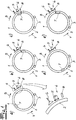
- the Fig. 1a shows an arrangement for the feed surface hardening of a closed curve 1 of a workpiece 2.
- the tread of a bearing ring is to be hardened, wherein the annular workpiece 2 is vertically or substantially vertically aligned and is supported on its underside on rollers 3.
- At least one of the rollers 3 is driven by a motor, not shown, so that the annular workpiece 2 can be rotated about its circumference.
- the arrangement furthermore comprises a hardening device 4 for induction hardening, which has an inductor 5 and a shower 6 downstream of the inductor 5 in the machining direction B.
- the machining direction B indicates the direction in which the hardening process continues. Accordingly is at the described movement of the workpiece 2 with a fixed hardening device 4, the machining direction B of the feed direction V opposite.
- a marking 7 is arranged as a separate part on the workpiece 2.
- the Fig. 1a shows the workpiece 2 immediately after placing on the rollers 3, the hardening device 4 is still inactive.
- the workpiece 2 is then further rotated in the feed direction V until the marking reaches the hardening device 4.
- the hardening device 4 comprises a sensor 8 which detects the marking 7.
- the sensor 8 detects both the beginning ( Fig. 1b ) as well as the end of the mark 7 ( Fig. 1c ), wherein the hardening device 4 is activated only when the sensor 8 has detected the end of the mark 7.
- the closed curve 1 of the workpiece 2 is then hardened in a uniform feed operation ( Fig. 1d ) until the marker 7 again reaches the sensor 8 ( Fig. 1e ).
- the hardening device 4 with the inductor 5 is then deactivated.
- Fig. 2 can be set by the marking 7 a remaining between an initial zone 9 and an end zone 10 slip zone 11 with a high accuracy and reproducibility.
- the width x of the mark corresponds to the distance between the start position and the end position of the inductor.
- the inductor usually has a conductor loop with two parallel conductor sections 12.
- the width of the uncured Slip zone 11 corresponds approximately to the width x of the marking 7 less the width of the inductor 5.
- a predetermined width of the slip zone 11 can be maintained with a very high accuracy and reproducibility.
- the hardening depth and the hardness at the initial zone 9 and the end zone 10 each decrease in the direction of the slip zone 11.
Landscapes
- Chemical & Material Sciences (AREA)
- Engineering & Computer Science (AREA)
- Physics & Mathematics (AREA)
- Thermal Sciences (AREA)
- Crystallography & Structural Chemistry (AREA)
- Mechanical Engineering (AREA)
- Materials Engineering (AREA)
- Metallurgy (AREA)
- Organic Chemistry (AREA)
- Electromagnetism (AREA)
- Heat Treatment Of Articles (AREA)
Description
- Die vorliegende Erfindung betrifft ein Verfahren zum induktiven Vorschub-Randschichthärten eines geschlossenen Kurvenzuges eines Werkstücks, insbesondere einer Lauffläche eines Lagerrings, wobei der geschlossene Kurvenzug und eine Härtevorrichtung, die einen Induktor und eine Brause aufweist, in einem Vorschubbetrieb relativ zueinander in einer Bearbeitungsrichtung bewegt werden, um den geschlossenen Kurvenzug ausgehend von einer Anfangszone bis zu einer Endzone zu härten, und wobei zwischen der Anfangszone und der Endzone eine ungehärtete Schlupfzone vorgesehen wird.
- Die zu härtende Fläche wird unter der Härtevorrichtung durch den mit Wechselstrom beaufschlagten Induktor stark erwärmt. In Bearbeitungsrichtung ist dem Induktor eine Brause nachgelagert, aus der eine Kühlflüssigkeit zum Abschrecken auf die zuvor aufgeheizte Fläche aufgebracht wird. Bei den üblicherweise eingesetzten Materialien wird in einer Randschicht durch die Erwärmung ein möglichst homogener Austenit erzeugt, wobei dann durch die Abschreckung mit einer hohen Abkühlgeschwindigkeit ein möglichst hoher Anteil an Martensit gebildet wird. Die Einhärtungstiefe hängt dabei von der Temperaturverteilung in der Randschicht ab und kann beim Induktionshärten beispielsweise durch die Frequenz, die insbesondere zwischen 3 kHz und 8 kHz liegen kann, und die Leistung verändert werden.
- Um den geschlossenen Kurvenzug, beispielsweise eine Lauffläche eines Lagerrings zu härten, kann der Kurvenzug kontinuierlich an einer feststehenden Härtevorrichtung vorbeibewegt werden. Genauso kann aber auch das Werkstück ruhen, während die Härtevorrichtung entlang der zu härtenden Oberfläche bewegt wird. Grundsätzlich besteht auch die Möglichkeit das Werkstück auf einem Träger aufzuspannen.
- Bei Lagerringen für Großwälzlager hat sich ein Verfahren bewährt, bei dem der Lagerring an einer feststehenden Härtevorrichtung vorbeibewegt wird. Insbesondere kann der Lagerring senkrecht oder schräg angeordnet sein, wobei dann die Bewegung des Lagerrings über abstützende Rollen erfolgen kann.
- Grundsätzlich besteht das Problem, dass bereits gehärtete Bereiche nicht erneut auf eine Temperatur aufgewärmt werden dürfen, bei der die Härteeigenschaften wieder verloren gehen. Bei einem geschlossenen Kurvenzug, beispielsweise einer Lauffläche eines Lagerrings, wird deshalb zwischen einer Anfangszone, an der mit der Härtung begonnen wird, und einer Endzone, die zuletzt gehärtet wird, eine ungehärtete Schlupfzone vorgesehen. Die ungehärtete Schlupfzone hat typischerweise eine Breite zwischen 10 mm und 20 mm, wobei es bei Wälzlagern bekannt ist, diese Schlupfzone zu hinterschleifen, damit dort die Wälzkörper nicht anliegen.
- Um eine Schlupfzone mit vorgegebener Breite zu erzeugen, muss die Position der Härtevorrichtung gegenüber der zu härtenden Fläche beim Ein- und Ausschalten der Leistung der Härtevorrichtung bekannt sein. Üblicherweise wird anhand orientierender Versuche eine geeignete Länge der Schlupfzone an einem Bauteil ermittelt, wobei dann die entsprechenden Parameter zur Steuerung eines Antriebs und der Härtevorrichtung auf die weiteren Werkstücke übertragen werden.
- Dabei ist jedoch zu berücksichtigen, dass bei den nachfolgenden Werkstücken die Breite der Schlupfzone aufgrund von Störeinflüssen variieren kann. Zunächst unterliegen die Werkstücke gewissen Toleranzen, so dass beispielsweise aufgrund etwas unterschiedlicher Durchmesser bei einem Lagerring sich auch ein unterschiedlicher Weg der Härtevorrichtung entlang der Lauffläche ergibt. Zusätzlich dehnt sich das Werkstück durch die Erwärmung mittels der Härtevorrichtung aus, wobei Schwankungen bei der thermischen Ausdehnung auch zu einer unterschiedlichen Länge der Schlupfzone führen können. Schließlich besteht das Problem, dass auch bei dem Antrieb der Härtevorrichtung bzw. des Werkstücks Ungenauigkeiten auftreten können. Wenn beispielsweise ein Lagerring in einer vertikalen Anordnung an seiner Unterseite auf Rollen abgestützt ist und von den Rollen angetrieben wird, führt ein Rutschen zwischen den Rollen und dem Lagerring auch zu einer Abweichung, wenn aus der Drehzahl bzw. der Drehposition der Rollen auf die Position des Lagerrings geschlossen wird.
- Aus den Druckschriften
DE 10 2005 006 701 B3 ,DE 10 2006 003 014 B1 undDE 10 2008 033 735 A1 sind Verfahren zum induktiven Randschichthärten einer Ringfläche eines Werkstücks bekannt. Bei diesem Verfahren wird eine Schlupfzone dadurch vermieden bzw. reduziert, dass zwei Induktoren eingesetzt werden, die ausgehend von einer Anfangszone gegenläufig bewegt werden. Die Anfangszone kann dabei vollständig gehärtet werden, weil durch beide Induktoren eine gleichmäßige oder zumindest weitgehend gleichmäßige Erwärmung erreicht werden kann. Die beiden Induktoren werden dann entgegengesetzt bewegt und kommen schließlich an der Endzone zusammen, die an der Ringfläche der Anfangszone gegenüberliegt. Auch die Endzone wird nur einmal erwärmt, wenn die beiden Induktoren sich von beiden Seiten annähern. Da die beiden Induktoren nicht beliebig eng aneinander herangebracht werden können, kann die Endzone zunächst mit einem Hilfsinduktor vorgewärmt werden. Nachteilig ist bei den beschriebenen Verfahren, dass insbesondere bei Großwälzlagern ein sehr erheblicher Aufwand hinsichtlich der Härtevorrichtung mit gegenläufigen Induktoren notwendig ist. - Aus der
JP-S 558403 - Der vorliegenden Erfindung liegt die Aufgabe zugrunde, ein Verfahren zum induktiven Vorschub-Randschichthärten eines geschlossenen Kurvenzuges eines Werkstücks anzugeben, bei dem auch bei großen Werkstücken ein Vorgabewert für die Breite einer ungehärteten Schlupfzone mit einer hohen Genauigkeit eingehalten werden kann.
- Zur Lösung dieser Aufgabe ist ausgehend von dem eingangs beschriebenen Verfahren zum Vorschub-Randschichthärten vorgesehen, dass eine gegenüber dem Werkstück ortsfeste Markierung angebracht wird, die Härtevorrichtung einen Sensor zur Erfassung der Markierung aufweist, der geschlossene Kurvenzug und die nicht aktive Härtevorrichtung relativ zueinander entlang der Bearbeitungsrichtung bewegt werden, bis der Sensor die Markierung erfasst, nach der Erfassung der Markierung durch den Sensor eine weitere Bewegung in Bearbeitungsrichtung erfolgt, bevor die Härtevorrichtung aktiviert wird, nachfolgend der Kurvenzug durch die Relativbewegung zwischen dem Kurvenzug und der aktiven Härtevorrichtung in dem Vorschubbetrieb gehärtet wird und die Markierung mittels des Sensors erneut erfasst und darauf die Härtevorrichtung direkt oder mit einer Verzögerung deaktiviert wird, wobei das Werkstück vertikal oder gegenüber der Vertikalen leicht verkippt angeordnet ist, das Werkstück an seiner Unterseite auf Rollen abgestützt wird und zumindest eine der Rollen durch einen Motor angetrieben wird. Erfindungsgemäß erfolgt eine direkte Bestimmung der Position des Werkstücks. Insbesondere wird die Markierung zweimal erfasst, um den Anfang und das Ende des Härtevorgangs festlegen zu können. Dabei ist zu berücksichtigen, dass zwischen dem Beginn und dem Ende der gehärteten Fläche die ungehärtete Schlupfzone freigelassen werden muss. Es ist deshalb vorgesehen, dass nach dem ersten Erfassen der Markierung durch den Sensor zunächst eine weitere Bewegung in Bearbeitungsrichtung erfolgt, bevor die Härtevorrichtung aktiviert wird. Aus dem Weg dieser weiteren Bewegung ergibt sich mittelbar die Breite der Schlupfzone. Dabei ist aber üblicherweise noch die Breite der Heizeinrichtung, also bei einer induktiven Erwärmung die Breite eines Induktors, zu berücksichtigen.
- Der nach der ersten Erfassung der Markierung durch den Sensor vor der Aktivierung der Härtevorrichtung zurückgelegte Weg kann durch eine Zeitverzögerung gesteuert werden oder mit Hilfe der Antriebseinrichtung ermittelt werden. Da dieser zusätzliche Weg gegenüber der gesamten Länge des geschlossenen Kurvenzugs klein ist, spielen die Störfaktoren wie ein Durchrutschen des Antriebs, Maßabweichungen oder unterschiedliche thermische Ausdehnungen dabei nur eine untergeordnete Rolle. Eine besonders genaue und zuverlässige Steuerung des Härtevorgangs ist aber dann möglich, wenn bei dem ersten Erfassen der Markierung in Bearbeitungsrichtung gesehen der Anfang und das Ende der Markierung erkannt werden, wobei die Härtevorrichtung aktiviert wird, wenn das Ende der Markierung erkannt wird. Die Deaktivierung der Härtevorrichtung erfolgt dann zweckmäßigerweise bei dem erneuten Erfassen der Markierung, wenn der Anfang der Markierung erkannt wird. Durch eine solche Vorgehensweise können jegliche Störeinflüsse vollständig ausgeschlossen werden. Darüber hinaus kann eine sehr einfache Steuerung des Verfahrens realisiert werden.
- Die Härtevorrichtung weist einen Induktor auf, der während des Härtens des Kurvenzuges mit einem Wechselstrom beaufschlagt wird, wobei die Härtevorrichtung des Weiteren eine in Bearbeitungsrichtung hinter dem Induktor angeordnete Brause zum Abschrecken aufweist. Insbesondere kann dem Induktor in Bearbeitungsrichtung auch ein Hilfsinduktor als Vorwärmer vorgelagert sein.
- Um gerade bei großen Werkstücken, beispielsweise Lagerringen von Großwälzlagern, eine leichte Handhabung zu ermöglichen, kann die Härteeinrichtung ortsfest angeordnet sein, wobei der geschlossene Kurvenzug des Werkstücks mit einem Antrieb an der Härteeinrichtung vorbeibewegt wird. Wie bereits zuvor erläutert, haben sich bei Lagerringen Anordnungen bewährt, bei denen die Lagerringe in einer vertikalen oder einer gegenüber der vertikalen leicht verkippten Anordnung an ihrer Unterseite auf Rollen abgestützt sind, wobei der zu bearbeitende Lagerring auch mittels der Rollen gedreht werden kann.
- Erfindungsgemäß ist die Markierung gegenüber dem Werkstück ortsfest angebracht. Damit ist gemeint, dass die relative Position der Markierung sich während des Härtevorgangs nicht gegenüber dem Werkstück ändert. So kann die Markierung unmittelbar an dem Werkstück angebracht sein. Wenn das Werkstück aber beispielsweise auf einen Träger aufgezogen wird, so kann die Markierung auch an dem Träger befestigt sein.
- Als Markierung können auf dem Werkstück oder auf einem das Werkstück aufnehmenden Träger beispielsweise dunkle Flächen, Kerben oder dergleichen vorgesehen werden. Besonders bevorzugt ist jedoch eine Ausgestaltung, bei der die Markierung als separates Teil lösbar an dem Werkstück befestigt ist. Möglich ist beispielsweise eine klemmende oder je nach Material auch eine magnetische Fixierung. Es ergibt sich der Vorteil, dass eine solche Markierung bei der Fertigung mehrerer Werkstücke von dem vorherigen Werkstück abgenommen und auf das nachfolgende Werkstück aufgesetzt werden kann. Eine unzureichende oder fehlerhafte Markierung ist dabei ausgeschlossen.
- Die Erfassung der Markierung kann beispielsweise optisch, insbesondere durch eine Lichtschranke, erfolgen. Bei einer als separates Teil aufgesetzten Markierung ist aber auch eine mechanische Erfassung möglich, die gerade auch unter sehr rauen Einsatzbedingungen besonders zuverlässig ist. Der Sensor ist dann als eine Art Taster ausgebildet, der die Anwesenheit der Markierung feststellen kann.
- Gegenstand der Erfindung ist auch eine Anordnung zum induktiven Vorschub-Randschichthärten eines geschlossenen Kurvenzuges eines Werkstücks, die im besonderen Maße zur Durchführung des zuvor beschriebenen Verfahrens geeignet ist. Die Anordnung umfasst eine Härtevorrichtung, die einen Induktor und eine Brause aufweist, und einen Antrieb für eine Relativbewegung zwischen dem Werkstück und der Härtevorrichtung. Erfindungsgemäß umfasst die Härtevorrichtung einen Sensor zur Erfassung einer gegenüber dem Werkstück ortsfest, vorzugsweise an dem Werkstück angebrachten Markierung, wobei das Werkstück an seiner Unterseite auf Rollen abgestützt ist und durch zumindest eine der Rollen antreibbar ist.
- Die Erfindung wird im Folgenden anhand einer lediglich ein Ausführungsbeispiel darstellenden Zeichnung erläutert. Es zeigen:
- Fig. 1a - 1e
- verschiedene Schritte während eines Verfahrens zum Vorschub-Randschichthärten einer Lauffläche eines Lagerrings,
- Fig. 2
- der Bereich der Lauffläche, in dem der Härtevorgang begonnen und beendet wird, wobei zwischen einer Anfangszone und einer Endzone eine ungehärtete Schlupfzone verbleibt.
- Die
Fig. 1a zeigt eine Anordnung zum Vorschub-Randschichthärten eines geschlossenen Kurvenzuges 1 eines Werkstücks 2. In dem konkreten Ausführungsbeispiel soll die Lauffläche eines Lagerrings gehärtet werden, wobei das ringförmige Werkstück 2 vertikal oder im Wesentlichen vertikal ausgerichtet ist und an seiner Unterseite auf Rollen 3 abgestützt ist. Zumindest eine der Rollen 3 wird durch einen nicht dargestellten Motor angetrieben, so dass das ringförmige Werkstück 2 um seinen Umfang gedreht werden kann. - Die Anordnung umfasst des Weiteren eine Härtevorrichtung 4 zum Induktionshärten, welche einen Induktor 5 und eine in Bearbeitungsrichtung B dem Induktor 5 nachgelagerte Brause 6 aufweist. Die Bearbeitungsrichtung B bezeichnet die Richtung, in welche sich der Härtevorgang fortsetzt. Entsprechend ist bei der beschriebenen Bewegung des Werkstücks 2 bei einer feststehenden Härtevorrichtung 4 die Bearbeitungsrichtung B der Vorschubrichtung V entgegengesetzt.
- Aus der
Fig. 1a ist des Weiteren zu erkennen, dass an dem Werkstück 2 eine Markierung 7 als separates Teil angeordnet ist. - Die
Fig. 1a zeigt das Werkstück 2 unmittelbar nach dem Auflegen auf die Rollen 3, wobei die Härtevorrichtung 4 noch inaktiv ist. - Das Werkstück 2 wird sodann in Vorschubrichtung V weitergedreht, bis die Markierung die Härtevorrichtung 4 erreicht. Die Härtevorrichtung 4 umfasst einen Sensor 8, der die Markierung 7 erfasst. In dem dargestellten Ausführungsbeispiel erkennt der Sensor 8 sowohl den Anfang (
Fig. 1b ) sowie das Ende der Markierung 7 (Fig. 1c ), wobei die Härtevorrichtung 4 erst aktiviert wird, wenn der Sensor 8 das Ende der Markierung 7 erkannt hat. Der geschlossene Kurvenzug 1 des Werkstücks 2 wird dann in einem gleichmäßigen Vorschubbetrieb gehärtet (Fig. 1d ), bis die Markierung 7 erneut den Sensor 8 erreicht (Fig. 1e ). Die Härtevorrichtung 4 mit dem Induktor 5 wird sodann deaktiviert. - Gemäß der
Fig. 2 kann durch die Markierung 7 eine zwischen einer Anfangszone 9 und einer Endzone 10 verbleibende Schlupfzone 11 mit einer hohen Genauigkeit und Reproduzierbarkeit eingestellt werden. Zur Verdeutlichung ist die Stellung des Induktors 5 zum Härtebeginn in der Anfangzone 9 sowie zum Härteende in der Endzone 10 dargestellt. Die Breite x der Markierung entspricht dabei dem Abstand zwischen der Startposition und der Endposition des Induktors. Dabei ist zu berücksichtigen, dass der Induktor üblicherweise eine Leiterschleife mit zwei parallelen Leiterabschnitten 12 aufweist. Die Breite der ungehärteten Schlupfzone 11 entspricht dabei in etwa der Breite x der Markierung 7 abzüglich der Breite des Induktors 5. Eine optimale Breite der Markierung 7 und damit der Schlupfzone 11 kann anhand von orientierenden Versuchen erfolgen. Erfindungsgemäß kann eine vorgegebene Breite der Schlupfzone 11 mit einer sehr hohen Genauigkeit und Reproduzierbarkeit eingehalten werden. In derFig. 2 ist des Weiteren angedeutet, dass die Einhärtetiefe und die Härte an der Anfangszone 9 und der Endzone 10 jeweils in Richtung der Schlupfzone 11 abnehmen.
Claims (7)
- Verfahren zum induktiven Vorschub-Randschichthärten eines geschlossenen Kurvenzuges (1) eines Werkstücks (2), insbesondere einer Lauffläche eines Lagerrings, wobei der geschlossene Kurvenzug (1) und eine Härtevorrichtung (4), die einen Induktor (5) und eine Brause (6) aufweist, in einem Vorschub- betrieb relativ zueinander in einer Bearbeitungsrichtung (B) bewegt werden, um den geschlossenen Kurvenzug (1) ausgehend von einer Anfangszone (9) bis zu einer Endzone (10) zu härten, und wobei zwischen der Anfangszone (9) und der Endzone (10) eine ungehärtete Schlupfzone (11) vorgesehen wird dadurch gekennzeichnet, dass eine gegenüber dem Werkstück (2) ortsfeste Markierung (7) angebracht wird, die Härtevorrichtung (4) einen Sensor (8) zur Erfassung der Markierung (7) aufweist, der geschlossene Kurvenzug (1) und die nicht aktive Härtevorrichtung (4) relativ zueinander entlang der Bearbeitungsrichtung (B) bewegt werden, bis der Sensor (8) die Markierung (7) erfasst, nach der Erfassung der Markierung (7) durch den Sensor (8) eine weitere Bewegung in Bearbeitungsrichtung (B) erfolgt, bevor die Härtevorrichtung (4) aktiviert wird, nachfolgend der Kurvenzug (1) durch die Relativbewegung zwischen dem Kurvenzug (1) und der aktiven Härtevorrichtung (4) in dem Vorschubbetrieb gehärtet wird und die Markierung (7) mittels des Sensors (8) erneut erfasst und darauf die Härtevorrichtung (4) deaktiviert wird, wobei das Werkstück vertikal oder gegenüber der Vertikalen leicht verkippt angeordnet ist, das Werkstück an seiner Unterseite auf Rollen abgestützt wird und zumindest eine der Rollen durch einen Motor angetrieben wird.
- Verfahren nach Anspruch 1 , dadurch gekennzeichnet, dass bei dem ersten Erfassen der Markierung (7) in Bearbeitungsrichtung (B) gesehen der Anfang und das Ende der Markierung (7) erkannt werden, wobei die Härtevorrichtung (4) aktiviert wird, wenn das Ende der Markierung (7) erkannt wird.
- Verfahren nach Anspruch 2, dadurch gekennzeichnet, dass die Härte- Vorrichtung (4) bei dem erneuten Erfassen der Markierung (7) deaktiviert wird, wenn der Anfang der Markierung (7) erkannt wird.
- Verfahren nach einem der Ansprüche 1 bis 3, dadurch gekennzeichnet, dass dem Induktor (5) in Bearbeitungsrichtung (B) gesehen ein Hilfsinduktor als Vor- wärmer vorgelagert ist.
- Verfahren nach einem der Ansprüche 1 bis 4, dadurch gekennzeichnet, dass die Härteeinrichtung ortsfest angeordnet ist, wobei der geschlossene Kurvenzug (1) des Werkstücks (2) mit einem Antrieb an der Härteeinrichtung (4) vor- beigeführt wird.
- Anordnung zum induktiven Vorschub-Randschichthärten eines geschlossenen Kurvenzuges (1) eines Werkstücks (2), insbesondere zur Durchführung des Verfahrens nach einem der Ansprüche 1 bis 5, mit einer Härtevorrichtung (4), die einen Induktor (5) und eine Brause (6) aufweist, und mit einem Antrieb für eine Relativbewegung zwischen dem Werkstück (2) und der Härtevorrichtung (4) dadurch gekennzeichnet, dass die Härtevorrichtung (4) einen Sensor (8) zur Erfassung einer gegenüber dem Werkstück (2) ortsfest angebrachten Markierung (7) umfasst, wobei das Werkstück vertikal oder gegenüber der Vertikalen leicht verkippt angeordnet und an seiner Unterseite auf Rollen abgestützt ist und durch zumindest eine der Rollen antreibbar ist.
- Anordnung nach Anspruch 6, dadurch gekennzeichnet, dass die Markierung (7) als separates Teil lösbar an dem Werkstück (2) befestigt ist.
Applications Claiming Priority (2)
| Application Number | Priority Date | Filing Date | Title |
|---|---|---|---|
| DE102012101304A DE102012101304A1 (de) | 2012-02-17 | 2012-02-17 | Verfahren und Anordnung zum Vorschub-Randschichthärten |
| PCT/EP2013/052331 WO2013120744A1 (de) | 2012-02-17 | 2013-02-06 | Verfahren und anordnung zum vorschub-randschichthärten |
Publications (2)
| Publication Number | Publication Date |
|---|---|
| EP2814991A1 EP2814991A1 (de) | 2014-12-24 |
| EP2814991B1 true EP2814991B1 (de) | 2019-04-03 |
Family
ID=47714062
Family Applications (1)
| Application Number | Title | Priority Date | Filing Date |
|---|---|---|---|
| EP13704057.2A Active EP2814991B1 (de) | 2012-02-17 | 2013-02-06 | Verfahren und anordnung zum vorschub-randschichthärten |
Country Status (7)
| Country | Link |
|---|---|
| US (1) | US10167527B2 (de) |
| EP (1) | EP2814991B1 (de) |
| CN (1) | CN104254623B (de) |
| DE (1) | DE102012101304A1 (de) |
| DK (1) | DK2814991T3 (de) |
| ES (1) | ES2732236T3 (de) |
| WO (1) | WO2013120744A1 (de) |
Families Citing this family (3)
| Publication number | Priority date | Publication date | Assignee | Title |
|---|---|---|---|---|
| ES2475141T3 (es) * | 2011-12-22 | 2014-07-10 | Imo Holding Gmbh | Disposición de rodamientos con zonas de temple inclinadas |
| DE102014102288A1 (de) * | 2014-02-21 | 2015-08-27 | Thyssenkrupp Ag | System, Fertigungsanlage und Verfahren |
| DE102020103299A1 (de) * | 2020-02-10 | 2021-08-12 | Sms Elotherm Gmbh | Verfahren zum induktiven Randschichthärten |
Family Cites Families (18)
| Publication number | Priority date | Publication date | Assignee | Title |
|---|---|---|---|---|
| US3716690A (en) | 1972-03-27 | 1973-02-13 | Parks Ohio Ind Inc | Apparatus for setting the air gap between an inductor and a valve seat |
| JPS514047A (en) * | 1974-07-01 | 1976-01-13 | Nippon Steel Corp | Kinzokuhenno hyomenketsukanbuteireho |
| JPS5828333B2 (ja) * | 1978-06-30 | 1983-06-15 | 高周波熱錬株式会社 | 環状体の誘導加熱・焼入方法および装置 |
| US4604510A (en) * | 1985-05-20 | 1986-08-05 | Tocco, Inc. | Method and apparatus for heat treating camshafts |
| US7192791B2 (en) * | 2003-06-19 | 2007-03-20 | Brooks Automation, Inc. | Semiconductor wafer having an edge based identification feature |
| JP2005146316A (ja) | 2003-11-12 | 2005-06-09 | Dai Ichi High Frequency Co Ltd | 金属旋回輪転動接触面の焼入れ方法及び装置 |
| DE102005006701B3 (de) | 2005-02-15 | 2006-03-30 | Rothe Erde Gmbh | Verfahren zum Herstellen eines Lagerringes für Großwälzlager |
| DE102005007984A1 (de) * | 2005-02-22 | 2006-08-24 | Schaeffler Kg | Wälzlagerring |
| DE102006003014B3 (de) * | 2006-01-23 | 2007-10-18 | Sms Elotherm Gmbh | Verfahren zum Härten eines einen geschlossenen Kurvenzug beschreibenden Werkstücks |
| US8099007B2 (en) * | 2006-11-21 | 2012-01-17 | Kabushiki Kaisha Toshiba | Fixing apparatus for image forming apparatus |
| ITTO20070263A1 (it) * | 2007-04-13 | 2008-10-14 | Saet Spa | Dispositivo e metodo per effettuare un trattamento di tempra ad induzione localizzata su componenti meccanici, in particolare ralle per cuscinetti di rotolamento di grandi dimensioni |
| JP4973476B2 (ja) * | 2007-12-10 | 2012-07-11 | Kddi株式会社 | 光信号品質監視装置 |
| JP2010133990A (ja) * | 2007-12-11 | 2010-06-17 | Ricoh Co Ltd | 回転部材の駆動制御装置と駆動制御方法及び画像形成装置 |
| JP2009287074A (ja) | 2008-05-28 | 2009-12-10 | Nsk Ltd | 高周波熱処理装置、高周波熱処理方法及び高周波熱処理方法を行った環状部品を備える転がり軸受 |
| DE102008033735A1 (de) | 2008-07-18 | 2010-02-18 | Rothe Erde Gmbh | Verfahren zum Härten wenigstens einer Laufbahn eines Lagerrings für ein Großwälzlager |
| DE102008038967B4 (de) | 2008-08-13 | 2011-11-10 | Efd Induction Gmbh | Vorrichtung zum Härten der Zähne von Zahnrädern durch induktive Wärmebehandlung |
| US9459656B2 (en) * | 2008-10-12 | 2016-10-04 | Samsung Electronics Co., Ltd. | Flexible devices and related methods of use |
| US20100243643A1 (en) * | 2009-03-30 | 2010-09-30 | Cesano Mariolino | Device and method for performing a localized induction hardening treatment on mechanical components, specifically thrust blocks for large-sized rolling bearings |
-
2012
- 2012-02-17 DE DE102012101304A patent/DE102012101304A1/de not_active Ceased
-
2013
- 2013-02-06 CN CN201380009762.1A patent/CN104254623B/zh not_active Expired - Fee Related
- 2013-02-06 EP EP13704057.2A patent/EP2814991B1/de active Active
- 2013-02-06 US US14/379,022 patent/US10167527B2/en active Active
- 2013-02-06 DK DK13704057.2T patent/DK2814991T3/da active
- 2013-02-06 ES ES13704057T patent/ES2732236T3/es active Active
- 2013-02-06 WO PCT/EP2013/052331 patent/WO2013120744A1/de not_active Ceased
Non-Patent Citations (1)
| Title |
|---|
| ROLLMANN JOERG ET AL: "Development of new application fields for large roller bearings by developing a new slide way hardening process", TECHFORUM, THYSSEN-KRUPP AG, DE, no. July, 1 July 2005 (2005-07-01), pages 78 - 83, XP009123763, ISSN: 1612-2763 * |
Also Published As
| Publication number | Publication date |
|---|---|
| CN104254623A (zh) | 2014-12-31 |
| US10167527B2 (en) | 2019-01-01 |
| EP2814991A1 (de) | 2014-12-24 |
| DE102012101304A1 (de) | 2013-08-22 |
| CN104254623B (zh) | 2018-09-04 |
| ES2732236T3 (es) | 2019-11-21 |
| DK2814991T3 (da) | 2019-07-15 |
| WO2013120744A1 (de) | 2013-08-22 |
| US20140367376A1 (en) | 2014-12-18 |
Similar Documents
| Publication | Publication Date | Title |
|---|---|---|
| EP1848833B1 (de) | Verfahren zum herstellen eines lagerringes für grosswälzlager mittels induktionshärten | |
| EP1977020B1 (de) | Verfahren zum härten eines einen geschlossenen kurvenzug beschreibenden werkstücks | |
| EP1375684B1 (de) | Verfahren zum Herstellen von Lagerringen für Grosswälzlager | |
| DE102014111501B4 (de) | Warmumformvorrichtung und Verfahren zum Herstellen von pressgehärteten Formbauteilen aus Stahlblech | |
| EP2814990B1 (de) | Verfahren zum induktiven randschichthärten einer ringfläche | |
| WO2013120744A1 (de) | Verfahren und anordnung zum vorschub-randschichthärten | |
| DE102013208478B4 (de) | Verfahren zum Randschichthärten eines metallischen Bauteils | |
| DE102015203483B4 (de) | Herstellungsverfahren für oberflächenbehandelte komponente und vorrichtung hierfür | |
| WO2018029255A1 (de) | Verfahren zum härten einer wälzkörperlaufbahn eines wälzlagerrings und wälzlagerring | |
| WO2016177733A1 (de) | Verfahren und vorrichtung zum induktiven vorschubhärten mit steuerbarem vorwärmen und einem zum vorwärmen und härten ausgebildeten induktor | |
| DE102022202465A1 (de) | Werkstückaufnahmevorrichtung | |
| EP3717670B1 (de) | Vorrichtung und induktives härteverfahren zum induktiven härten von metallischen werkstücken sowie verwendung der vorrichtung | |
| AT504706B1 (de) | Verfahren und vorrichtung zur wärmebehandlung von metallischen langprodukten | |
| EP1721994B1 (de) | Induktionserwärmungsanlage zum gleichzeitigen Erwärmen von mehreren Werkstücken | |
| WO2021160655A1 (de) | Verfahren zum induktiven randschichthärten | |
| EP4107296A1 (de) | Verfahren zum induktiven randschichthärten | |
| WO2015124585A1 (de) | System, fertigungsanlage und verfahren | |
| CH711031B1 (de) | Verfahren zur Herstellung von Führungsschienen für ein Linearwälzlager. | |
| DE102005056876A1 (de) | Verfahren und Vorrichtung zum induktiven Härten von Nocken einer Nockenwelle | |
| DE102015107855A1 (de) | Vorrichtung und Verfahren zum Erwärmen von Kunststoffvorformlingen mit wegstellbarer Bewegungseinrichtung | |
| DE891088C (de) | Verfahren und Vorrichtung zum fortschreitenden induktiven Oberflaechenhaerten | |
| DE1583413C (de) | Induktionshartevomchtung fur Walzen | |
| CH712700A2 (de) | Verfahren zur Herstellung von Führungsschienen für ein Linearwälzlager. | |
| DE102006014303A1 (de) | Verfahren und Vorrichtung zum Verformen einer mit mindestens einer Markierung versehenen Folie |
Legal Events
| Date | Code | Title | Description |
|---|---|---|---|
| PUAI | Public reference made under article 153(3) epc to a published international application that has entered the european phase |
Free format text: ORIGINAL CODE: 0009012 |
|
| 17P | Request for examination filed |
Effective date: 20140917 |
|
| AK | Designated contracting states |
Kind code of ref document: A1 Designated state(s): AL AT BE BG CH CY CZ DE DK EE ES FI FR GB GR HR HU IE IS IT LI LT LU LV MC MK MT NL NO PL PT RO RS SE SI SK SM TR |
|
| AX | Request for extension of the european patent |
Extension state: BA ME |
|
| DAX | Request for extension of the european patent (deleted) | ||
| STAA | Information on the status of an ep patent application or granted ep patent |
Free format text: STATUS: EXAMINATION IS IN PROGRESS |
|
| 17Q | First examination report despatched |
Effective date: 20170323 |
|
| RAP1 | Party data changed (applicant data changed or rights of an application transferred) |
Owner name: THYSSENKRUPP ROTHE ERDE GMBH |
|
| REG | Reference to a national code |
Ref country code: DE Ref legal event code: R079 Ref document number: 502013012539 Country of ref document: DE Free format text: PREVIOUS MAIN CLASS: C21D0009400000 Ipc: C21D0009000000 |
|
| RIC1 | Information provided on ipc code assigned before grant |
Ipc: H05B 6/10 20060101ALI20180710BHEP Ipc: C21D 1/10 20060101ALI20180710BHEP Ipc: C21D 11/00 20060101ALI20180710BHEP Ipc: H05B 6/06 20060101ALI20180710BHEP Ipc: C21D 9/40 20060101ALI20180710BHEP Ipc: C21D 9/00 20060101AFI20180710BHEP Ipc: C21D 9/34 20060101ALI20180710BHEP |
|
| GRAP | Despatch of communication of intention to grant a patent |
Free format text: ORIGINAL CODE: EPIDOSNIGR1 |
|
| STAA | Information on the status of an ep patent application or granted ep patent |
Free format text: STATUS: GRANT OF PATENT IS INTENDED |
|
| INTG | Intention to grant announced |
Effective date: 20180820 |
|
| GRAJ | Information related to disapproval of communication of intention to grant by the applicant or resumption of examination proceedings by the epo deleted |
Free format text: ORIGINAL CODE: EPIDOSDIGR1 |
|
| STAA | Information on the status of an ep patent application or granted ep patent |
Free format text: STATUS: EXAMINATION IS IN PROGRESS |
|
| GRAP | Despatch of communication of intention to grant a patent |
Free format text: ORIGINAL CODE: EPIDOSNIGR1 |
|
| STAA | Information on the status of an ep patent application or granted ep patent |
Free format text: STATUS: GRANT OF PATENT IS INTENDED |
|
| INTC | Intention to grant announced (deleted) | ||
| GRAS | Grant fee paid |
Free format text: ORIGINAL CODE: EPIDOSNIGR3 |
|
| INTG | Intention to grant announced |
Effective date: 20190123 |
|
| GRAA | (expected) grant |
Free format text: ORIGINAL CODE: 0009210 |
|
| STAA | Information on the status of an ep patent application or granted ep patent |
Free format text: STATUS: THE PATENT HAS BEEN GRANTED |
|
| AK | Designated contracting states |
Kind code of ref document: B1 Designated state(s): AL AT BE BG CH CY CZ DE DK EE ES FI FR GB GR HR HU IE IS IT LI LT LU LV MC MK MT NL NO PL PT RO RS SE SI SK SM TR |
|
| REG | Reference to a national code |
Ref country code: GB Ref legal event code: FG4D Free format text: NOT ENGLISH |
|
| REG | Reference to a national code |
Ref country code: CH Ref legal event code: EP Ref country code: AT Ref legal event code: REF Ref document number: 1115801 Country of ref document: AT Kind code of ref document: T Effective date: 20190415 |
|
| REG | Reference to a national code |
Ref country code: DE Ref legal event code: R096 Ref document number: 502013012539 Country of ref document: DE |
|
| REG | Reference to a national code |
Ref country code: IE Ref legal event code: FG4D Free format text: LANGUAGE OF EP DOCUMENT: GERMAN |
|
| REG | Reference to a national code |
Ref country code: DK Ref legal event code: T3 Effective date: 20190708 |
|
| REG | Reference to a national code |
Ref country code: NL Ref legal event code: MP Effective date: 20190403 |
|
| REG | Reference to a national code |
Ref country code: LT Ref legal event code: MG4D |
|
| PG25 | Lapsed in a contracting state [announced via postgrant information from national office to epo] |
Ref country code: NL Free format text: LAPSE BECAUSE OF FAILURE TO SUBMIT A TRANSLATION OF THE DESCRIPTION OR TO PAY THE FEE WITHIN THE PRESCRIBED TIME-LIMIT Effective date: 20190403 |
|
| PG25 | Lapsed in a contracting state [announced via postgrant information from national office to epo] |
Ref country code: SE Free format text: LAPSE BECAUSE OF FAILURE TO SUBMIT A TRANSLATION OF THE DESCRIPTION OR TO PAY THE FEE WITHIN THE PRESCRIBED TIME-LIMIT Effective date: 20190403 Ref country code: PT Free format text: LAPSE BECAUSE OF FAILURE TO SUBMIT A TRANSLATION OF THE DESCRIPTION OR TO PAY THE FEE WITHIN THE PRESCRIBED TIME-LIMIT Effective date: 20190803 Ref country code: AL Free format text: LAPSE BECAUSE OF FAILURE TO SUBMIT A TRANSLATION OF THE DESCRIPTION OR TO PAY THE FEE WITHIN THE PRESCRIBED TIME-LIMIT Effective date: 20190403 Ref country code: FI Free format text: LAPSE BECAUSE OF FAILURE TO SUBMIT A TRANSLATION OF THE DESCRIPTION OR TO PAY THE FEE WITHIN THE PRESCRIBED TIME-LIMIT Effective date: 20190403 Ref country code: NO Free format text: LAPSE BECAUSE OF FAILURE TO SUBMIT A TRANSLATION OF THE DESCRIPTION OR TO PAY THE FEE WITHIN THE PRESCRIBED TIME-LIMIT Effective date: 20190703 Ref country code: CZ Free format text: LAPSE BECAUSE OF FAILURE TO SUBMIT A TRANSLATION OF THE DESCRIPTION OR TO PAY THE FEE WITHIN THE PRESCRIBED TIME-LIMIT Effective date: 20190403 Ref country code: HR Free format text: LAPSE BECAUSE OF FAILURE TO SUBMIT A TRANSLATION OF THE DESCRIPTION OR TO PAY THE FEE WITHIN THE PRESCRIBED TIME-LIMIT Effective date: 20190403 Ref country code: LT Free format text: LAPSE BECAUSE OF FAILURE TO SUBMIT A TRANSLATION OF THE DESCRIPTION OR TO PAY THE FEE WITHIN THE PRESCRIBED TIME-LIMIT Effective date: 20190403 |
|
| REG | Reference to a national code |
Ref country code: ES Ref legal event code: FG2A Ref document number: 2732236 Country of ref document: ES Kind code of ref document: T3 Effective date: 20191121 |
|
| PG25 | Lapsed in a contracting state [announced via postgrant information from national office to epo] |
Ref country code: RS Free format text: LAPSE BECAUSE OF FAILURE TO SUBMIT A TRANSLATION OF THE DESCRIPTION OR TO PAY THE FEE WITHIN THE PRESCRIBED TIME-LIMIT Effective date: 20190403 Ref country code: GR Free format text: LAPSE BECAUSE OF FAILURE TO SUBMIT A TRANSLATION OF THE DESCRIPTION OR TO PAY THE FEE WITHIN THE PRESCRIBED TIME-LIMIT Effective date: 20190704 Ref country code: PL Free format text: LAPSE BECAUSE OF FAILURE TO SUBMIT A TRANSLATION OF THE DESCRIPTION OR TO PAY THE FEE WITHIN THE PRESCRIBED TIME-LIMIT Effective date: 20190403 Ref country code: LV Free format text: LAPSE BECAUSE OF FAILURE TO SUBMIT A TRANSLATION OF THE DESCRIPTION OR TO PAY THE FEE WITHIN THE PRESCRIBED TIME-LIMIT Effective date: 20190403 Ref country code: BG Free format text: LAPSE BECAUSE OF FAILURE TO SUBMIT A TRANSLATION OF THE DESCRIPTION OR TO PAY THE FEE WITHIN THE PRESCRIBED TIME-LIMIT Effective date: 20190703 |
|
| PG25 | Lapsed in a contracting state [announced via postgrant information from national office to epo] |
Ref country code: IS Free format text: LAPSE BECAUSE OF FAILURE TO SUBMIT A TRANSLATION OF THE DESCRIPTION OR TO PAY THE FEE WITHIN THE PRESCRIBED TIME-LIMIT Effective date: 20190803 |
|
| REG | Reference to a national code |
Ref country code: DE Ref legal event code: R097 Ref document number: 502013012539 Country of ref document: DE |
|
| REG | Reference to a national code |
Ref country code: DE Ref legal event code: R081 Ref document number: 502013012539 Country of ref document: DE Owner name: THYSSENKRUPP ROTHE ERDE GERMANY GMBH, DE Free format text: FORMER OWNER: THYSSENKRUPP ROTHE ERDE GMBH, 44137 DORTMUND, DE |
|
| PG25 | Lapsed in a contracting state [announced via postgrant information from national office to epo] |
Ref country code: EE Free format text: LAPSE BECAUSE OF FAILURE TO SUBMIT A TRANSLATION OF THE DESCRIPTION OR TO PAY THE FEE WITHIN THE PRESCRIBED TIME-LIMIT Effective date: 20190403 Ref country code: RO Free format text: LAPSE BECAUSE OF FAILURE TO SUBMIT A TRANSLATION OF THE DESCRIPTION OR TO PAY THE FEE WITHIN THE PRESCRIBED TIME-LIMIT Effective date: 20190403 Ref country code: SK Free format text: LAPSE BECAUSE OF FAILURE TO SUBMIT A TRANSLATION OF THE DESCRIPTION OR TO PAY THE FEE WITHIN THE PRESCRIBED TIME-LIMIT Effective date: 20190403 |
|
| PLBE | No opposition filed within time limit |
Free format text: ORIGINAL CODE: 0009261 |
|
| STAA | Information on the status of an ep patent application or granted ep patent |
Free format text: STATUS: NO OPPOSITION FILED WITHIN TIME LIMIT |
|
| PG25 | Lapsed in a contracting state [announced via postgrant information from national office to epo] |
Ref country code: SM Free format text: LAPSE BECAUSE OF FAILURE TO SUBMIT A TRANSLATION OF THE DESCRIPTION OR TO PAY THE FEE WITHIN THE PRESCRIBED TIME-LIMIT Effective date: 20190403 |
|
| 26N | No opposition filed |
Effective date: 20200106 |
|
| PG25 | Lapsed in a contracting state [announced via postgrant information from national office to epo] |
Ref country code: TR Free format text: LAPSE BECAUSE OF FAILURE TO SUBMIT A TRANSLATION OF THE DESCRIPTION OR TO PAY THE FEE WITHIN THE PRESCRIBED TIME-LIMIT Effective date: 20190403 |
|
| PG25 | Lapsed in a contracting state [announced via postgrant information from national office to epo] |
Ref country code: SI Free format text: LAPSE BECAUSE OF FAILURE TO SUBMIT A TRANSLATION OF THE DESCRIPTION OR TO PAY THE FEE WITHIN THE PRESCRIBED TIME-LIMIT Effective date: 20190403 |
|
| REG | Reference to a national code |
Ref country code: CH Ref legal event code: PL |
|
| REG | Reference to a national code |
Ref country code: BE Ref legal event code: MM Effective date: 20200229 |
|
| PG25 | Lapsed in a contracting state [announced via postgrant information from national office to epo] |
Ref country code: MC Free format text: LAPSE BECAUSE OF FAILURE TO SUBMIT A TRANSLATION OF THE DESCRIPTION OR TO PAY THE FEE WITHIN THE PRESCRIBED TIME-LIMIT Effective date: 20190403 Ref country code: LU Free format text: LAPSE BECAUSE OF NON-PAYMENT OF DUE FEES Effective date: 20200206 |
|
| PG25 | Lapsed in a contracting state [announced via postgrant information from national office to epo] |
Ref country code: CH Free format text: LAPSE BECAUSE OF NON-PAYMENT OF DUE FEES Effective date: 20200229 Ref country code: LI Free format text: LAPSE BECAUSE OF NON-PAYMENT OF DUE FEES Effective date: 20200229 |
|
| PG25 | Lapsed in a contracting state [announced via postgrant information from national office to epo] |
Ref country code: IE Free format text: LAPSE BECAUSE OF NON-PAYMENT OF DUE FEES Effective date: 20200206 |
|
| PG25 | Lapsed in a contracting state [announced via postgrant information from national office to epo] |
Ref country code: BE Free format text: LAPSE BECAUSE OF NON-PAYMENT OF DUE FEES Effective date: 20200229 |
|
| REG | Reference to a national code |
Ref country code: AT Ref legal event code: MM01 Ref document number: 1115801 Country of ref document: AT Kind code of ref document: T Effective date: 20200206 |
|
| PG25 | Lapsed in a contracting state [announced via postgrant information from national office to epo] |
Ref country code: AT Free format text: LAPSE BECAUSE OF NON-PAYMENT OF DUE FEES Effective date: 20200206 |
|
| PGFP | Annual fee paid to national office [announced via postgrant information from national office to epo] |
Ref country code: GB Payment date: 20220223 Year of fee payment: 10 Ref country code: DK Payment date: 20220218 Year of fee payment: 10 Ref country code: DE Payment date: 20220217 Year of fee payment: 10 |
|
| PG25 | Lapsed in a contracting state [announced via postgrant information from national office to epo] |
Ref country code: MT Free format text: LAPSE BECAUSE OF FAILURE TO SUBMIT A TRANSLATION OF THE DESCRIPTION OR TO PAY THE FEE WITHIN THE PRESCRIBED TIME-LIMIT Effective date: 20190403 Ref country code: CY Free format text: LAPSE BECAUSE OF FAILURE TO SUBMIT A TRANSLATION OF THE DESCRIPTION OR TO PAY THE FEE WITHIN THE PRESCRIBED TIME-LIMIT Effective date: 20190403 |
|
| PGFP | Annual fee paid to national office [announced via postgrant information from national office to epo] |
Ref country code: IT Payment date: 20220218 Year of fee payment: 10 Ref country code: FR Payment date: 20220216 Year of fee payment: 10 |
|
| PG25 | Lapsed in a contracting state [announced via postgrant information from national office to epo] |
Ref country code: MK Free format text: LAPSE BECAUSE OF FAILURE TO SUBMIT A TRANSLATION OF THE DESCRIPTION OR TO PAY THE FEE WITHIN THE PRESCRIBED TIME-LIMIT Effective date: 20190403 |
|
| PGFP | Annual fee paid to national office [announced via postgrant information from national office to epo] |
Ref country code: ES Payment date: 20220426 Year of fee payment: 10 |
|
| REG | Reference to a national code |
Ref country code: DE Ref legal event code: R119 Ref document number: 502013012539 Country of ref document: DE |
|
| REG | Reference to a national code |
Ref country code: DK Ref legal event code: EBP Effective date: 20230228 |
|
| GBPC | Gb: european patent ceased through non-payment of renewal fee |
Effective date: 20230206 |
|
| PG25 | Lapsed in a contracting state [announced via postgrant information from national office to epo] |
Ref country code: GB Free format text: LAPSE BECAUSE OF NON-PAYMENT OF DUE FEES Effective date: 20230206 |
|
| PG25 | Lapsed in a contracting state [announced via postgrant information from national office to epo] |
Ref country code: IT Free format text: LAPSE BECAUSE OF NON-PAYMENT OF DUE FEES Effective date: 20230206 Ref country code: GB Free format text: LAPSE BECAUSE OF NON-PAYMENT OF DUE FEES Effective date: 20230206 Ref country code: FR Free format text: LAPSE BECAUSE OF NON-PAYMENT OF DUE FEES Effective date: 20230228 Ref country code: DK Free format text: LAPSE BECAUSE OF NON-PAYMENT OF DUE FEES Effective date: 20230228 Ref country code: DE Free format text: LAPSE BECAUSE OF NON-PAYMENT OF DUE FEES Effective date: 20230901 |
|
| REG | Reference to a national code |
Ref country code: ES Ref legal event code: FD2A Effective date: 20240405 |
|
| PG25 | Lapsed in a contracting state [announced via postgrant information from national office to epo] |
Ref country code: ES Free format text: LAPSE BECAUSE OF NON-PAYMENT OF DUE FEES Effective date: 20230207 |
|
| PG25 | Lapsed in a contracting state [announced via postgrant information from national office to epo] |
Ref country code: ES Free format text: LAPSE BECAUSE OF NON-PAYMENT OF DUE FEES Effective date: 20230207 |