EP2813651A2 - Arretierung für eine insbesondere aus Glas bestehende Tür - Google Patents
Arretierung für eine insbesondere aus Glas bestehende Tür Download PDFInfo
- Publication number
- EP2813651A2 EP2813651A2 EP14001694.0A EP14001694A EP2813651A2 EP 2813651 A2 EP2813651 A2 EP 2813651A2 EP 14001694 A EP14001694 A EP 14001694A EP 2813651 A2 EP2813651 A2 EP 2813651A2
- Authority
- EP
- European Patent Office
- Prior art keywords
- locking device
- door
- pin
- locking pin
- sleeve
- Prior art date
- Legal status (The legal status is an assumption and is not a legal conclusion. Google has not performed a legal analysis and makes no representation as to the accuracy of the status listed.)
- Granted
Links
Images


Classifications
-
- E—FIXED CONSTRUCTIONS
- E05—LOCKS; KEYS; WINDOW OR DOOR FITTINGS; SAFES
- E05C—BOLTS OR FASTENING DEVICES FOR WINGS, SPECIALLY FOR DOORS OR WINDOWS
- E05C19/00—Other devices specially designed for securing wings, e.g. with suction cups
- E05C19/18—Portable devices specially adapted for securing wings
- E05C19/188—Removably mounted securing devices, e.g. devices clamped to the wing or the frame
-
- E—FIXED CONSTRUCTIONS
- E05—LOCKS; KEYS; WINDOW OR DOOR FITTINGS; SAFES
- E05B—LOCKS; ACCESSORIES THEREFOR; HANDCUFFS
- E05B15/00—Other details of locks; Parts for engagement by bolts of fastening devices
- E05B15/10—Bolts of locks or night latches
- E05B15/101—Spring-retracted bolts
-
- E—FIXED CONSTRUCTIONS
- E05—LOCKS; KEYS; WINDOW OR DOOR FITTINGS; SAFES
- E05B—LOCKS; ACCESSORIES THEREFOR; HANDCUFFS
- E05B35/00—Locks for use with special keys or a plurality of keys ; keys therefor
- E05B35/008—Locks for use with special keys or a plurality of keys ; keys therefor for simple tool-like keys
-
- E—FIXED CONSTRUCTIONS
- E05—LOCKS; KEYS; WINDOW OR DOOR FITTINGS; SAFES
- E05B—LOCKS; ACCESSORIES THEREFOR; HANDCUFFS
- E05B65/00—Locks or fastenings for special use
- E05B65/0025—Locks or fastenings for special use for glass wings
-
- E—FIXED CONSTRUCTIONS
- E05—LOCKS; KEYS; WINDOW OR DOOR FITTINGS; SAFES
- E05C—BOLTS OR FASTENING DEVICES FOR WINGS, SPECIALLY FOR DOORS OR WINDOWS
- E05C1/00—Fastening devices with bolts moving rectilinearly
- E05C1/02—Fastening devices with bolts moving rectilinearly without latching action
- E05C1/06—Fastening devices with bolts moving rectilinearly without latching action with operating handle or equivalent member moving otherwise than rigidly with the bolt
-
- E—FIXED CONSTRUCTIONS
- E05—LOCKS; KEYS; WINDOW OR DOOR FITTINGS; SAFES
- E05C—BOLTS OR FASTENING DEVICES FOR WINGS, SPECIALLY FOR DOORS OR WINDOWS
- E05C19/00—Other devices specially designed for securing wings, e.g. with suction cups
- E05C19/18—Portable devices specially adapted for securing wings
- E05C19/184—Portable devices specially adapted for securing wings a portable member cooperating with a fixed member or an opening on the wing or the frame, for locking the wing
-
- E—FIXED CONSTRUCTIONS
- E05—LOCKS; KEYS; WINDOW OR DOOR FITTINGS; SAFES
- E05C—BOLTS OR FASTENING DEVICES FOR WINGS, SPECIALLY FOR DOORS OR WINDOWS
- E05C5/00—Fastening devices with bolts moving otherwise than only rectilinearly and only pivotally or rotatively
- E05C5/02—Fastening devices with bolts moving otherwise than only rectilinearly and only pivotally or rotatively both moving axially and turning about their axis to secure the wing
- E05C5/04—Fastening devices with bolts moving otherwise than only rectilinearly and only pivotally or rotatively both moving axially and turning about their axis to secure the wing performing both movements simultaneously, e.g. screwing into a keeper
Definitions
- the present invention relates to a lock for a esp. Made of glass door, with a door arranged on the fitting, which receives a locking pin.
- the lock can be positioned freely on the door. Since the lock is only clamped between the door and the floor or the ceiling, but not firmly connected to the door, it can also be removed again at any time. In addition, the production of a chamfer is considerably less expensive than that of a bore. Due to the inventive design of the locking of the leg, which faces the movable door, omitted and thus the safety distance can be maintained.
- the chamfer is arranged on the lower edge of the door. This has the advantage that the fitting in the region of the lower edge attached and thus the door can be braced against the ground.
- the locking pin cooperates advantageously with an anchor plate which can be mounted on the floor or on the ceiling.
- the fitting has according to a preferred embodiment, a block-shaped housing, from which the chamfer embracing approach projects laterally.
- the locking pin is slidably mounted in the direction of the anchor plate in a through bore of the housing.
- For engagement in the anchor plate of the locking pin advantageously carries at one end a pin.
- the locking pin is provided at its other end with an engagement opening for a tool.
- an internal thread is advantageously determined, in which the locking pin is screwed.
- Another embodiment is characterized in that in the housing a through hole at right angles intersecting bearing bore is provided.
- the locking pin is formed in this embodiment as a tubular sleeve, at the bottom of the pin is arranged.
- a balancing tappet is advantageously inserted into the sleeve.
- a compensating spring located within the sleeve is arranged between the bottom of the sleeve and the balance plunger.
- the sleeve is supported according to a preferred embodiment of a sleeve surrounding the outside coil spring on a stop of the housing.
- the compensating spring is preferably formed stronger than the coil spring.
- the eccentric shaft has according to a preferred embodiment, two outer portions and an intermediate eccentric portion, which is in operative connection with the balance ram.
- an engagement opening for a tool is advantageously arranged.
- the through hole in the housing is advantageously closed with a cap.
- the locking device according to the invention is arranged on the lower edge of a completely made of glass door 1.
- the locking device according to the invention can also be used on the upper edge, on a door 1 without a glass pane or a door 1 consisting only partially of glass.
- a chamfer 2 is formed at its lower edge, which extends at least over part of the width of the door 1.
- This chamfer 2 cooperates with a fitting which has a substantially cuboidal or block-shaped housing 3, from which a projection 4 embracing the chamfer 2 projects laterally.
- the projection 4 is arranged in an end region of the housing 3 and extends over its entire width.
- a through hole 5 is arranged, in which a locking pin 6 is slidably mounted.
- the locking pin 6 has at its one end a pin 7, which can be brought into engagement with a bottom plate arranged anchor plate 8, so that the door 1 is braced against the ground and positively held in position.
- the housing 3 Since the housing 3 is braced only between door 1 and floor, but not firmly connected to the door 1, it can always be removed again from the door. Of course, the housing 3 also connected to the door 1, z. B. glued.
- an internal thread 9 is defined in the through hole 5 of the housing 3.
- this internal thread 9 provided with an external locking pin 6 is screwed.
- a tool such as a screwdriver, the locking pin 6 can be rotated into the internal thread 9 and are brought into or out of engagement with the anchor plate 8.
- This embodiment is inexpensive and can compensate for bumps at any time.
- a through hole 5 at right angles intersecting bearing bore 11 is arranged in the housing 3, in which an eccentric shaft 12 is mounted, with the aid of the locking pin 6 can be moved out of the housing 3 out.
- the eccentric shaft 12 has two outer portion 12a and an eccentric portion 12b therebetween.
- an engagement opening 10 for a tool such as a hexagon socket key, provided by means of which the eccentric shaft 12 can be rotated.
- a marking 13 is provided, which provides information about the respective position of the locking pin 6.
- the locking pin 6 consists in this embodiment of a tubular sleeve, at the bottom of the pin 7 is formed.
- a balance plunger 14 is inserted into the sleeve, which is in operative connection with the eccentric portion 12b.
- the compensating tappet 14 is supported on the bottom of the sleeve via a compensating spring 15, for example a helical spring, arranged inside the sleeve.
- the sleeve or the locking pin 6 is surrounded by a helical spring 16 which is supported on the one hand on a radially projecting shoulder 17 of the sleeve and on the other hand on a stop 18 of the housing 3.
- the through hole 5 in the housing 3 is closed on the pin 7 opposite side with a cap 19.
- the embodiment according to the Figures 3 and 4 Although not as inexpensive as the embodiment of the FIGS. 1 and 2 However, it allows a determination of the door 1 with half a revolution of a frontally inserted into the engagement opening 10 of the eccentric shaft 12 tool. In addition, it has a spring-loaded balance of uneven floors.
- the housing 3 is attached with its neck 4 down to the chamfer 3 of the door 1 and aligned with the anchor plate 8.
- the eccentric shaft 12 is rotated by means of a tool.
- the locking pin 6 is pressed down over the compensating spring 15 and the compensating tappet 14 into the armature plate 8.
- the balancing spring 15 is compressed, so that even at a To a small extent between the lower edge of the door 1 and the upper edge anchor plate 8, the eccentric shaft 12 can be rotated by the required 180 ° twist.
- the eccentric shaft 12 additionally has an upper surface, so that after a 180 ° rotation again a stable position is achieved.
- the compensating spring 15 must be designed much stronger than the coil spring 16.
- each disc can be made up and down with a chamfer. As a result, each disc can be used universally for left or right versions.
- the internal thread 9 is replaceable by a threaded sleeve, in particular, if the housing is not made of aluminum, but of plastic.
Landscapes
- Engineering & Computer Science (AREA)
- Mechanical Engineering (AREA)
- Hinges (AREA)
- Securing Of Glass Panes Or The Like (AREA)
Abstract
Description
- Die vorliegende Erfindung betrifft eine Arretierung für eine insbes. aus Glas bestehende Tür, mit einem an der Tür angeordneten Beschlag, welcher einen Arretierstift aufnimmt.
- Bekannte Arretierungen werden über einen Beschlag vorgenommen, der in einer Bohrung an der Tür festgelegt ist. Hierdurch ist die Position der Arretierung fest vorgegeben und kann z. B. bei bauseitig auftretenden Problemen nicht mehr verändert werden. Zusätzlich ist eine Bohrung, insbes. wenn die Tür aus Glas ist, eine teure Angelegenheit.
- Üblicherweise werden solche Arretierungen auch mit einem Aufsteckschuh ausgeführt. Hierbei wird ein U-förmiger Klotz auf dem Glas verklebt oder verklemmt. Ein Schenkel des U-Klotzes dient hierbei nur der Befestigung zum Glas, der andere Schenkel nimmt zusätzlich noch eine Arretierung auf. Der Nachteil dieser Konstruktion ist es, dass aneinander vorbeifahrende Glaselemente aufgrund des Befestigungsschenkels meist einen größeren Abstand zueinander benötigen als die Norm zulässt.
- Es ist daher Aufgabe der vorliegenden Erfindung, eine Arretierung der eingangs genannten Art bereit zu stellen, welche einerseits kostengünstig herstellbar ist und darüber hinaus auch noch eine nachträgliche Justierung ermöglicht.
- Diese Aufgabe wird bei einem Arretierung für eine insbes. aus Glas bestehende Tür, mit einem an der Tür angeordneten Beschlag, welcher einen Arretierstift aufnimmt, erfindungsgemäß dadurch gelöst, dass die Tür mit einer Fase versehen ist und dass der Beschlag einen die Fase umgreifenden Ansatz aufweist.
- Aufgrund der erfindungsgemäßen Ausgestaltung kann die Arretierung frei an der Tür positioniert werden. Da die Arretierung nur zwischen der Tür und dem Boden bzw. der Decke verspannt, aber nicht fest mit der Tür verbunden ist, kann sie auch jederzeit wieder abgenommen werden. Darüber hinaus ist die Herstellung einer Fase erheblich kostengünstiger als die einer Bohrung. Durch die erfindungsgemäße Ausführung der Arretierung kann der Schenkel, der dem beweglichen Türflügel zugewandt ist, entfallen und der Sicherheitsabstand somit eingehalten werden.
- Die Unteransprüche haben vorteilhafte Weiterbildungen der Erfindung zum Inhalt.
- Gemäß einer vorteilhaften Weiterbildung ist die Fase an der Unterkante der Tür angeordnet. Dies hat den Vorteil, dass der Beschlag im Bereich der Unterkante angebracht und dadurch die Tür gegen den Boden verspannt werden kann.
- Der Arretierstift wirkt vorteilhafterweise mit einer Ankerplatte zusammen, die am Boden bzw. an der Decke angebracht sein kann.
- Der Beschlag weist gemäß einer bevorzugten Ausgestaltung ein blockförmiges Gehäuse auf, von welchem der die Fase umgreifende Ansatz seitlich absteht.
- Gemäß einer vorteilhaften Ausgestaltung ist der Arretierstift in Richtung auf die Ankerplatte verschiebbar in einer Durchgangsbohrung des Gehäuses gelagert.
- Zum Eingriff in die Ankerplatte trägt der Arretierstift vorteilhafterweise an seinem einen Ende einen Zapfen.
- Gemäß einer ersten Ausführungsform ist der Arretierstift an seinem anderen Ende mit einer Eingriffsöffnung für ein Werkzeug versehen.
- In der Durchgangsbohrung ist vorteilhafterweise ein Innengewinde festgelegt, in welche der Arretierstift eingeschraubt ist.
- Eine andere Ausführungsform zeichnet sich dadurch aus, dass in dem Gehäuse eine die Durchgangsbohrung rechtwinklig kreuzende Lagerbohrung vorgesehen ist.
- In dieser Lagerbohrung ist gemäß einer vorteilhaften Weiterbildung eine Exzenterwelle gelagert, mit deren Hilfe der Arretierstift aus dem Gehäuse heraus bewegt werden kann.
- Der Arretierstift ist bei dieser Ausführungsform als rohrförmige Hülse ausgebildet, an deren Boden der Zapfen angeordnet ist.
- An dem dem Zapfen gegenüberliegenden Ende der Hülse ist vorteilhafterweise ein Ausgleichsstößel in die Hülse eingesetzt.
- Gemäß einer vorteilhaften Ausgestaltung ist zwischen dem Boden der Hülse und dem Ausgleichsstößel eine innerhalb der Hülse liegende Ausgleichfeder angeordnet.
- Die Hülse stützt sich gemäß einer bevorzugten Weiterbildung über eine die Hülse außen umgebende Schraubenfeder an einem Anschlag des Gehäuses ab.
- Die Ausgleichsfeder ist bevorzugt stärker als die Schraubenfeder ausgebildet.
- Die Exzenterwelle weist gemäß einer bevorzugten Ausführung zwei äußere Abschnitte und einen dazwischen liegenden Exzenterabschnitt auf, der mit dem Ausgleichsstößel in Wirkverbindung steht.
- In zumindest einem der äußeren Abschnitte der Exzenterwelle ist vorteilhafterweise eine Eingriffsöffnung für ein Werkzeug angeordnet.
- Die Durchgangsbohrung in dem Gehäuse ist vorteilhafterweise mit einer Abdeckkappe verschließbar.
- Weitere Einzelheiten, Merkmale und Vorteile der Erfindung ergeben sich aus nachfolgender Beschreibung anhand der Zeichnungen. Es zeigen:
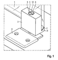
- Figur 1
- eine perspektivische Ansicht einer erfindungsgemäßen Arretierung gemäß einer ersten Ausführungsform,
- Figur 2
- eine weitere perspektivische Ansicht der erfindungsgemäßen Arretierung gemäß der ersten Ausführungsform,
- Figur 3
- eine perspektivische Ansicht einer erfindungsgemäßen Arretierung gemäß einer zweiten Ausführungsform, und
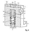
- Figur 4
- einen Schnitt durch die erfindungsgemäße Arretierung gemäß der zweiten Ausführungsform.
- In den Figuren ist die erfindungsgemäße Arretierung an der Unterkante einer voliständig aus Glas bestehenden Tür 1 angeordnet. Die erfindungsgemäße Arretierung kann jedoch auch an der Oberkante, an einer Tür 1 ohne Glasscheibe oder einer nur teilweise aus Glas bestehenden Tür 1 eingesetzt werden.
- An der Tür 1 ist an deren Unterkante eine Fase 2 ausgebildet, die sich zumindest über einen Teil der Breite der Tür 1 erstreckt. Diese Fase 2 wirkt mit einem Beschlag zusammen, der ein im Wesentlichen quader- oder blockförmiges Gehäuse 3 aufweist, von welchem ein die Fase 2 umgreifender Ansatz 4 seitlich absteht. Der Ansatz 4 ist in einem Endbereich des Gehäuses 3 angeordnet und erstreckt sich über dessen gesamte Breite.
- In dem Gehäuse 3, das beispielsweise aus Aluminium gefertigt sein kann, ist eine Durchgangsbohrung 5 angeordnet, in der ein Arretierstift 6 verschiebbar gelagert ist. Der Arretierstift 6 weist an seinem einen Ende einen Zapfen 7 auf, welcher mit einer am Boden angeordneten Ankerplatte 8 in Eingriff bringbar ist, so dass die Tür 1 gegen den Boden verspannt und formschlüssig in Position gehalten wird.
- Da das Gehäuse 3 nur zwischen Tür 1 und Boden verspannt, aber nicht fest mit der Tür 1 verbunden ist, kann es jederzeit auch wieder von der Tür abgenommen werden. Natürlich kann das Gehäuse 3 auch fest mit der Tür 1 verbunden, z. B. verklebt sein.
- Für die Mechanik, mittels der die Verschiebung des Arretierstiftes 6 erfolgt, werden nachfolgend zwei Ausführungsvarianten erläutert.
- Gemäß einer ersten in den
Figuren 1 und2 dargestellten Ausführungsform ist in der Durchgangsbohrung 5 des Gehäuses 3 ein Innengewinde 9 festgelegt. In dieses Innengewinde 9 ist der mit einem Außengewinde versehene Arretierstift 6 eingeschraubt. Über eine an der dem Zapfen 7 gegenüberliegenden Ende des Arretierstiftes 6 angeordnete Eingriffsöffnung 10 für ein Werkzeug, beispielsweise ein Schraubendreher, kann der Arretierstift 6 in das Innengewinde 9 verdreht und so in oder außer Eingriff mit der Ankerplatte 8 gebracht werden. - Diese Ausführungsform ist preisgünstig und kann auch Bodenunebenheiten jederzeit ausgleichen.
- Gemäß einer zweiten in den
Figuren 3 und4 dargestellten Ausführungsform ist in dem Gehäuse 3 eine die Durchgangsbohrung 5 rechtwinklig kreuzende Lagerbohrung 11 angeordnet, in welcher eine Exzenterwelle 12 gelagert ist, mit deren Hilfe der Arretierstift 6 aus dem Gehäuse 3 heraus bewegt werden kann. - Die Exzenterwelle 12 weist zwei äußere Abschnitt 12a und einen dazwischen liegenden Exzenterabschnitt 12b auf. In zumindest einem der äußeren Abschnitt 12a ist eine Eingriffsöffnung 10 für ein Werkzeug, beispielsweise ein Innensechskantschlüssel, vorgesehen, mit dessen Hilfe die Exzenterwelle 12 verdreht werden kann. Im Bereich der Eingriffsöffnung 10 ist eine Markierung 13 vorgesehen, welche Auskunft über die jeweilige Stellung des Arretierstiftes 6 gibt.
- Der Arretierstift 6 besteht bei dieser Ausführungsform aus einer rohrförmigen Hülse, an deren Boden der Zapfen 7 ausgebildet ist. An dem dem Zapfen 7 gegenüberliegenden Ende ist ein Ausgleichsstößel 14 in die Hülse eingesetzt, der mit dem Exzenterabschnitt 12b in Wirkverbindung steht. Der Ausgleichstößel 14 stützt sich über eine innerhalb der Hülse angeordnete Ausgleichsfeder 15, beispielsweise eine Schraubenfeder, an dem Boden der Hülse ab.
- Die Hülse bzw. der Arretierstift 6 ist von einer Schraubenfeder 16 umgeben, die sich einerseits an einer radial vorstehenden Schulter 17 der Hülse und andererseits an einem Anschlag 18 des Gehäuses 3 abstützt.
- Die Durchgangsbohrung 5 in dem Gehäuse 3 ist auf der dem Zapfen 7 entgegengesetzten Seite mit einer Abdeckkappe 19 verschlossen.
- Die Ausführungsform nach den
Figuren 3 und4 ist zwar nicht so kostengünstig wie die Ausführungsform nach denFiguren 1 und2 , sie erlaubt jedoch eine Feststellung der Tür 1 mit einer halben Umdrehung eines stirnseitig in die Eingriffsöffnung 10 der Exzenterwelle 12 eingesetzten Werkzeugs. Darüber hinaus hat sie einen federbelasteten Ausgleich von Bodenunebenheiten. - Bei der Montage wird das Gehäuse 3 mit seinem Ansatz 4 unten an die Fase 3 der Tür 1 angesetzt und auf die Ankerplatte 8 ausgerichtet. Um die Tür 1 festzusetzen wird die Exzenterwelle 12 mittels eines Werkzeuges gedreht. Dadurch wird der Arretierstift 6 über die Ausgleichsfeder 15 und den Ausgleichsstößel 14 nach unten in die Ankerplatte 8 gedrückt. Sobald der Boden des Arretierstiftes 6 auf der Ankerplatte 8 aufsetzt, wird die Ausgleichfeder 15 komprimiert, so dass auch bei einem zu geringen Maß zwischen Unterkante Tür 1 und Oberkante Ankerplatte 8 die Exzenterwelle 12 um die benötigte 180°-Verdrehung gedreht werden kann. Hierbei hat die Exzenterwelle 12 zusätzlich eine obere Fläche, so dass nach einer 180°-Drehung wieder eine stabile Position erreicht wird. Um die Funktion zu gewährleisten, muss die Ausgleichfeder 15 deutlich stärker als die Schraubenfeder 16 ausgelegt werden.
- Beim Rückdrehen der Exzenterwelle 12 wird der Arretierstift 6 über die Schraubenfeder 16 in die Ausgangslage zurückgestellt. Hierdurch ist die Arretierung geöffnet und kann abgenommen werden.
- Zusätzlich kann jede Scheibe oben und unten mit einer Fase ausgeführt sein. Hierdurch kann jede Scheibe universell für linke oder rechte Ausführungen genutzt werden.
- Abschließend ist anzumerken, dass das Innengewinde 9 durch eine Gewindehülse ersetzbar ist, insbesondere, wenn das Gehäuse etwa nicht aus Aluminium, sondern aus Kunststoff gefertigt ist.
- Die vorhergehende Beschreibung der vorliegenden Erfindung dient nur zu illustrativen Zwecken und nicht zum Zwecke der Beschränkung der Erfindung. Im Rahmen der Erfindung sind verschiedene Änderungen und Modifikationen möglich, ohne den Umfang der Erfindung sowie ihrer Äquivalente zu verlassen.
-
- 1
- Tür
- 2
- Fase
- 3
- Gehäuse
- 4
- Ansatz
- 5
- Durchgangsbohrung
- 6
- Arretierstift
- 7
- Zapfen
- 8
- Ankerplatte
- 9
- Innengwinde
- 10
- Eingriffsöffnung
- 11
- Lagerbohrung
- 12
- Exzenterwelle
- 12a
- äußerer Abschnitt
- 13
- Exzenterabschnitt
- 14
- Ausgleichsstößel
- 15
- Ausgleichsfeder
- 16
- Schraubenfeder
- 17
- Schulter
- 18
- Anschlag
- 19
- Abdeckkappe
Claims (18)
- Arretierung für eine insbes. aus Glas bestehende Tür, mit einem an der Tür angeordneten Beschlag, welcher einen Arretierstift aufnimmt, dadurch gekennzeichnet, dass die Tür (1) mit einer Fase (2) versehen ist und dass der Beschlag einen die Fase (2) umgreifenden Ansatz (4) aufweist.
- Arretierung nach Anspruch 1, dadurch gekennzeichnet, dass die Fase (2) an der Unterkante der Tür (1) angeordnet ist.
- Arretierung nach Anspruch 1 oder 2, dadurch gekennzeichnet, dass der Arretierstift (6) mit einer am Boden oder einer Decke angeordneten Ankerplatte (8) zusammenwirkt.
- Arretierung nach einem der vorhergehenden Ansprüche, dadurch gekennzeichnet, dass der Beschlag ein blockförmiges Gehäuse (3) aufweist, von welchem der die Fase (2) umgreifende Ansatz (4) seitlich absteht.
- Arretierung nach einem der Ansprüche 3 bis 4, dadurch gekennzeichnet, dass der Arretierstift (6) in Richtung auf die Ankerplatte (8) verschiebbar in einer Durchgangsbohrung (5) des Gehäuses (3) gelagert ist.
- Arretierung nach einem der Ansprüche 3 bis 5, dadurch gekennzeichnet, dass der Arretierstift (6) an seinem einen Ende einen Zapfen (7) zum Eingriff in die Ankerplatte (8) trägt.
- Arretierung nach einem der Ansprüche 4 bis 6, dadurch gekennzeichnet, dass der Arretierstift (6) an seinem anderen Ende mit einer Eingriffsöffnung (10) für ein Werkzeug versehen ist.
- Arretierung nach der Ansprüche 5 bis 7, dadurch gekennzeichnet, dass in der Durchgangsbohrung (5) ein Innengewinde (9) festgelegt ist, in welchem der Arretierstift (6) eingeschraubt ist.
- Arretierung nach Anspruch 5, dadurch gekennzeichnet, dass in dem Gehäuse (3) eine die Durchgangsbohrung (5) rechtwinklig kreuzende Lagerbohrung (11) vorgesehen ist.
- Arretierung nach Anspruch 9, dadurch gekennzeichnet, dass in der Lagerbohrung (11) eine Exzenterwelle (12) gelagert ist, mit deren Hilfe der Arretierstift (6) aus dem Gehäuse (3) heraus bewegt werden kann.
- Arretierung nach Anspruch 10, dadurch gekennzeichnet, dass der Arretierstift (6) als rohrförmige Hülse ausgebildet ist, an deren Boden der Zapfen (7) angeordnet ist.
- Arretierung nach Anspruch 11, dadurch gekennzeichnet, dass an dem dem Zapfen gegenüberliegenden Ende der Hülse ein Ausgleichsstößel (14) in die Hülse eingesetzt ist.
- Arretierung nach Anspruch 12, dadurch gekennzeichnet, dass zwischen dem Boden der Hülse und dem Ausgleichsstößel (14) eine innerhalb der Hülse liegende Ausgleichfeder (15) angeordnet ist.
- Arretierung nach einem der Ansprüche 11 bis 13, dadurch gekennzeichnet, dass sich die Hülse über eine die Hülse außen umgebende Schraubenfeder (16) an einem Anschlag (18) des Gehäuses (3) abstützt.
- Arretierung nach Anspruch 14, dadurch gekennzeichnet, dass die Ausgleichsfeder (15) stärker als die Schraubenfeder (16) ausgebildet ist.
- Arretierung nach einem der Ansprüche 10 bis 15, dadurch gekennzeichnet, dass die Exzenterwelle (12) zwei äußere Abschnitte (12a) und einen dazwischen liegenden Exzenterabschnitt (12b) aufweist, der mit dem Ausgleichsstößel (14) in Wirkverbindung steht.
- Arretierung nach Anspruch 16, dadurch gekennzeichnet, dass in zumindest einem der äußeren Abschnitte (12a) der Exzenterwelle (12) eine Eingriffsöffnung (10) für ein Werkzeug angeordnet ist.
- Arretierung nach einem der Ansprüche 9 bis 17, dadurch gekennzeichnet, dass die Durchgangsbohrung (5) mit einer Abdeckkappe (19) verschließbar ist.
Applications Claiming Priority (1)
| Application Number | Priority Date | Filing Date | Title |
|---|---|---|---|
| DE102013106058.7A DE102013106058A1 (de) | 2013-06-11 | 2013-06-11 | Arretierung für eine insbes. aus Glas bestehende Tür |
Publications (3)
| Publication Number | Publication Date |
|---|---|
| EP2813651A2 true EP2813651A2 (de) | 2014-12-17 |
| EP2813651A3 EP2813651A3 (de) | 2015-11-18 |
| EP2813651B1 EP2813651B1 (de) | 2017-10-18 |
Family
ID=50731885
Family Applications (1)
| Application Number | Title | Priority Date | Filing Date |
|---|---|---|---|
| EP14001694.0A Active EP2813651B1 (de) | 2013-06-11 | 2014-05-14 | Insbesondere aus Glas bestehende Tür umfassend eine Arretierung |
Country Status (2)
| Country | Link |
|---|---|
| EP (1) | EP2813651B1 (de) |
| DE (1) | DE102013106058A1 (de) |
Family Cites Families (8)
| Publication number | Priority date | Publication date | Assignee | Title |
|---|---|---|---|---|
| US3103713A (en) * | 1960-08-29 | 1963-09-17 | Amerock Corp | Sash lock |
| FR1382843A (fr) * | 1964-02-21 | 1964-12-18 | Serrure amovible pour la fermeture et le verrouillage de portes en vitre | |
| BE711500A (de) * | 1967-03-18 | 1968-07-01 | ||
| GB2024299A (en) * | 1978-07-04 | 1980-01-09 | Speedcraft Ltd | Locks |
| GB8404728D0 (en) * | 1984-02-23 | 1984-03-28 | Chubb & Sons Lock & Safe Co | Security fittings |
| DE19644638A1 (de) * | 1996-10-17 | 1998-04-23 | Necdet Oezyurt | Feststell- und Sicherungsvorrichtung für Schiebetüren |
| SK282503B6 (sk) * | 1998-04-03 | 2002-10-08 | Jozef �Ervenko | Príchytka plošných materiálov |
| US6164098A (en) * | 1998-09-16 | 2000-12-26 | Howard Miller Clock Company | Frameless glass door lock |
-
2013
- 2013-06-11 DE DE102013106058.7A patent/DE102013106058A1/de not_active Withdrawn
-
2014
- 2014-05-14 EP EP14001694.0A patent/EP2813651B1/de active Active
Non-Patent Citations (1)
| Title |
|---|
| None |
Also Published As
| Publication number | Publication date |
|---|---|
| EP2813651A3 (de) | 2015-11-18 |
| DE102013106058A1 (de) | 2014-12-11 |
| EP2813651B1 (de) | 2017-10-18 |
Similar Documents
| Publication | Publication Date | Title |
|---|---|---|
| EP2730727B1 (de) | Zylinderschloss | |
| DE202010008393U1 (de) | Verbindungsvorrichtung | |
| DE102011080795B3 (de) | Befestigungsanordnung zur Befestigung eines Bauteils an einer Nut eines Fensters, einer Tür oder dergleichen | |
| WO2014060530A1 (de) | System mit türbetätigungsteil und schliesszylinder | |
| EP2816243A1 (de) | Befestigungselement | |
| EP2439361B1 (de) | Schlosseinrichtung für insbesondere Türen | |
| DE202007008534U1 (de) | Sicherheitsschraube | |
| CH644666A5 (de) | Scharnier. | |
| DE102010060764B3 (de) | Anschraubtasche für die Aufnahme von Bandzapfen eines Türbandes | |
| DE102013011163A1 (de) | Elektromagnetische Türverriegelung, insbes. für Türen in Rettungswegen | |
| EP2602418B1 (de) | Eckverbindungsset | |
| EP2792830A2 (de) | Halteelement zur Halterung eines Beschlagteils | |
| EP2113624A2 (de) | Tür- oder Fenstersicherungsvorrichtung | |
| EP2813651B1 (de) | Insbesondere aus Glas bestehende Tür umfassend eine Arretierung | |
| EP3187671A1 (de) | Verriegelungsvorrichtung als einbruchssicherung für z. b. fenster und türen | |
| DE10249382B4 (de) | Gelenkband | |
| DE8534096U1 (de) | Zylinderschloß mit einer Nachschließsicherung | |
| DE102018101285A1 (de) | Eckverbinder | |
| DE102012104863B3 (de) | Türbandanordnung mit einem Türband und einem Aufnahmeelement | |
| DE102009018268A1 (de) | Wandanschlusseinrichtung, sowie Duschkabinenelement | |
| EP3162994B1 (de) | Antriebsgetriebe für einen treibstangenbeschlag | |
| EP1922467B1 (de) | Band für türen, fenster oder dergleichen | |
| DE102004012278A1 (de) | Rosette für einen Türbeschlag | |
| EP2305932B1 (de) | Bandteil mit verdeckter Verschraubung | |
| DE2818761A1 (de) | Tuerschliesser |
Legal Events
| Date | Code | Title | Description |
|---|---|---|---|
| 17P | Request for examination filed |
Effective date: 20140514 |
|
| AK | Designated contracting states |
Kind code of ref document: A2 Designated state(s): AL AT BE BG CH CY CZ DE DK EE ES FI FR GB GR HR HU IE IS IT LI LT LU LV MC MK MT NL NO PL PT RO RS SE SI SK SM TR |
|
| AX | Request for extension of the european patent |
Extension state: BA ME |
|
| PUAI | Public reference made under article 153(3) epc to a published international application that has entered the european phase |
Free format text: ORIGINAL CODE: 0009012 |
|
| PUAL | Search report despatched |
Free format text: ORIGINAL CODE: 0009013 |
|
| AK | Designated contracting states |
Kind code of ref document: A3 Designated state(s): AL AT BE BG CH CY CZ DE DK EE ES FI FR GB GR HR HU IE IS IT LI LT LU LV MC MK MT NL NO PL PT RO RS SE SI SK SM TR |
|
| AX | Request for extension of the european patent |
Extension state: BA ME |
|
| RIC1 | Information provided on ipc code assigned before grant |
Ipc: E05B 9/00 20060101ALI20151013BHEP Ipc: E05C 1/00 20060101ALI20151013BHEP Ipc: E05B 65/00 20060101AFI20151013BHEP |
|
| R17P | Request for examination filed (corrected) |
Effective date: 20160512 |
|
| RBV | Designated contracting states (corrected) |
Designated state(s): AL AT BE BG CH CY CZ DE DK EE ES FI FR GB GR HR HU IE IS IT LI LT LU LV MC MK MT NL NO PL PT RO RS SE SI SK SM TR |
|
| RAP1 | Party data changed (applicant data changed or rights of an application transferred) |
Owner name: DORMAKABA DEUTSCHLAND GMBH |
|
| GRAP | Despatch of communication of intention to grant a patent |
Free format text: ORIGINAL CODE: EPIDOSNIGR1 |
|
| STAA | Information on the status of an ep patent application or granted ep patent |
Free format text: STATUS: GRANT OF PATENT IS INTENDED |
|
| INTG | Intention to grant announced |
Effective date: 20170512 |
|
| GRAS | Grant fee paid |
Free format text: ORIGINAL CODE: EPIDOSNIGR3 |
|
| GRAA | (expected) grant |
Free format text: ORIGINAL CODE: 0009210 |
|
| STAA | Information on the status of an ep patent application or granted ep patent |
Free format text: STATUS: THE PATENT HAS BEEN GRANTED |
|
| AK | Designated contracting states |
Kind code of ref document: B1 Designated state(s): AL AT BE BG CH CY CZ DE DK EE ES FI FR GB GR HR HU IE IS IT LI LT LU LV MC MK MT NL NO PL PT RO RS SE SI SK SM TR |
|
| REG | Reference to a national code |
Ref country code: GB Ref legal event code: FG4D Free format text: NOT ENGLISH |
|
| REG | Reference to a national code |
Ref country code: CH Ref legal event code: EP |
|
| REG | Reference to a national code |
Ref country code: AT Ref legal event code: REF Ref document number: 938097 Country of ref document: AT Kind code of ref document: T Effective date: 20171115 Ref country code: IE Ref legal event code: FG4D Free format text: LANGUAGE OF EP DOCUMENT: GERMAN |
|
| REG | Reference to a national code |
Ref country code: DE Ref legal event code: R096 Ref document number: 502014005827 Country of ref document: DE |
|
| REG | Reference to a national code |
Ref country code: CH Ref legal event code: NV Representative=s name: RENTSCH PARTNER AG, CH |
|
| REG | Reference to a national code |
Ref country code: NL Ref legal event code: MP Effective date: 20171018 |
|
| REG | Reference to a national code |
Ref country code: LT Ref legal event code: MG4D |
|
| PG25 | Lapsed in a contracting state [announced via postgrant information from national office to epo] |
Ref country code: NL Free format text: LAPSE BECAUSE OF FAILURE TO SUBMIT A TRANSLATION OF THE DESCRIPTION OR TO PAY THE FEE WITHIN THE PRESCRIBED TIME-LIMIT Effective date: 20171018 |
|
| PG25 | Lapsed in a contracting state [announced via postgrant information from national office to epo] |
Ref country code: LT Free format text: LAPSE BECAUSE OF FAILURE TO SUBMIT A TRANSLATION OF THE DESCRIPTION OR TO PAY THE FEE WITHIN THE PRESCRIBED TIME-LIMIT Effective date: 20171018 Ref country code: ES Free format text: LAPSE BECAUSE OF FAILURE TO SUBMIT A TRANSLATION OF THE DESCRIPTION OR TO PAY THE FEE WITHIN THE PRESCRIBED TIME-LIMIT Effective date: 20171018 Ref country code: FI Free format text: LAPSE BECAUSE OF FAILURE TO SUBMIT A TRANSLATION OF THE DESCRIPTION OR TO PAY THE FEE WITHIN THE PRESCRIBED TIME-LIMIT Effective date: 20171018 Ref country code: SE Free format text: LAPSE BECAUSE OF FAILURE TO SUBMIT A TRANSLATION OF THE DESCRIPTION OR TO PAY THE FEE WITHIN THE PRESCRIBED TIME-LIMIT Effective date: 20171018 Ref country code: NO Free format text: LAPSE BECAUSE OF FAILURE TO SUBMIT A TRANSLATION OF THE DESCRIPTION OR TO PAY THE FEE WITHIN THE PRESCRIBED TIME-LIMIT Effective date: 20180118 |
|
| PG25 | Lapsed in a contracting state [announced via postgrant information from national office to epo] |
Ref country code: GR Free format text: LAPSE BECAUSE OF FAILURE TO SUBMIT A TRANSLATION OF THE DESCRIPTION OR TO PAY THE FEE WITHIN THE PRESCRIBED TIME-LIMIT Effective date: 20180119 Ref country code: RS Free format text: LAPSE BECAUSE OF FAILURE TO SUBMIT A TRANSLATION OF THE DESCRIPTION OR TO PAY THE FEE WITHIN THE PRESCRIBED TIME-LIMIT Effective date: 20171018 Ref country code: HR Free format text: LAPSE BECAUSE OF FAILURE TO SUBMIT A TRANSLATION OF THE DESCRIPTION OR TO PAY THE FEE WITHIN THE PRESCRIBED TIME-LIMIT Effective date: 20171018 Ref country code: LV Free format text: LAPSE BECAUSE OF FAILURE TO SUBMIT A TRANSLATION OF THE DESCRIPTION OR TO PAY THE FEE WITHIN THE PRESCRIBED TIME-LIMIT Effective date: 20171018 Ref country code: BG Free format text: LAPSE BECAUSE OF FAILURE TO SUBMIT A TRANSLATION OF THE DESCRIPTION OR TO PAY THE FEE WITHIN THE PRESCRIBED TIME-LIMIT Effective date: 20180118 Ref country code: IS Free format text: LAPSE BECAUSE OF FAILURE TO SUBMIT A TRANSLATION OF THE DESCRIPTION OR TO PAY THE FEE WITHIN THE PRESCRIBED TIME-LIMIT Effective date: 20180218 |
|
| REG | Reference to a national code |
Ref country code: DE Ref legal event code: R097 Ref document number: 502014005827 Country of ref document: DE |
|
| PG25 | Lapsed in a contracting state [announced via postgrant information from national office to epo] |
Ref country code: EE Free format text: LAPSE BECAUSE OF FAILURE TO SUBMIT A TRANSLATION OF THE DESCRIPTION OR TO PAY THE FEE WITHIN THE PRESCRIBED TIME-LIMIT Effective date: 20171018 Ref country code: SK Free format text: LAPSE BECAUSE OF FAILURE TO SUBMIT A TRANSLATION OF THE DESCRIPTION OR TO PAY THE FEE WITHIN THE PRESCRIBED TIME-LIMIT Effective date: 20171018 Ref country code: DK Free format text: LAPSE BECAUSE OF FAILURE TO SUBMIT A TRANSLATION OF THE DESCRIPTION OR TO PAY THE FEE WITHIN THE PRESCRIBED TIME-LIMIT Effective date: 20171018 Ref country code: CZ Free format text: LAPSE BECAUSE OF FAILURE TO SUBMIT A TRANSLATION OF THE DESCRIPTION OR TO PAY THE FEE WITHIN THE PRESCRIBED TIME-LIMIT Effective date: 20171018 |
|
| PLBE | No opposition filed within time limit |
Free format text: ORIGINAL CODE: 0009261 |
|
| STAA | Information on the status of an ep patent application or granted ep patent |
Free format text: STATUS: NO OPPOSITION FILED WITHIN TIME LIMIT |
|
| PG25 | Lapsed in a contracting state [announced via postgrant information from national office to epo] |
Ref country code: PL Free format text: LAPSE BECAUSE OF FAILURE TO SUBMIT A TRANSLATION OF THE DESCRIPTION OR TO PAY THE FEE WITHIN THE PRESCRIBED TIME-LIMIT Effective date: 20171018 Ref country code: SM Free format text: LAPSE BECAUSE OF FAILURE TO SUBMIT A TRANSLATION OF THE DESCRIPTION OR TO PAY THE FEE WITHIN THE PRESCRIBED TIME-LIMIT Effective date: 20171018 Ref country code: IT Free format text: LAPSE BECAUSE OF FAILURE TO SUBMIT A TRANSLATION OF THE DESCRIPTION OR TO PAY THE FEE WITHIN THE PRESCRIBED TIME-LIMIT Effective date: 20171018 Ref country code: RO Free format text: LAPSE BECAUSE OF FAILURE TO SUBMIT A TRANSLATION OF THE DESCRIPTION OR TO PAY THE FEE WITHIN THE PRESCRIBED TIME-LIMIT Effective date: 20171018 |
|
| 26N | No opposition filed |
Effective date: 20180719 |
|
| PG25 | Lapsed in a contracting state [announced via postgrant information from national office to epo] |
Ref country code: MT Free format text: LAPSE BECAUSE OF FAILURE TO SUBMIT A TRANSLATION OF THE DESCRIPTION OR TO PAY THE FEE WITHIN THE PRESCRIBED TIME-LIMIT Effective date: 20171018 |
|
| PG25 | Lapsed in a contracting state [announced via postgrant information from national office to epo] |
Ref country code: SI Free format text: LAPSE BECAUSE OF FAILURE TO SUBMIT A TRANSLATION OF THE DESCRIPTION OR TO PAY THE FEE WITHIN THE PRESCRIBED TIME-LIMIT Effective date: 20171018 |
|
| GBPC | Gb: european patent ceased through non-payment of renewal fee |
Effective date: 20180514 |
|
| REG | Reference to a national code |
Ref country code: BE Ref legal event code: MM Effective date: 20180531 |
|
| PG25 | Lapsed in a contracting state [announced via postgrant information from national office to epo] |
Ref country code: MC Free format text: LAPSE BECAUSE OF FAILURE TO SUBMIT A TRANSLATION OF THE DESCRIPTION OR TO PAY THE FEE WITHIN THE PRESCRIBED TIME-LIMIT Effective date: 20171018 |
|
| REG | Reference to a national code |
Ref country code: IE Ref legal event code: MM4A |
|
| PG25 | Lapsed in a contracting state [announced via postgrant information from national office to epo] |
Ref country code: LU Free format text: LAPSE BECAUSE OF NON-PAYMENT OF DUE FEES Effective date: 20180514 |
|
| PG25 | Lapsed in a contracting state [announced via postgrant information from national office to epo] |
Ref country code: IE Free format text: LAPSE BECAUSE OF NON-PAYMENT OF DUE FEES Effective date: 20180514 Ref country code: GB Free format text: LAPSE BECAUSE OF NON-PAYMENT OF DUE FEES Effective date: 20180514 Ref country code: FR Free format text: LAPSE BECAUSE OF NON-PAYMENT OF DUE FEES Effective date: 20180531 |
|
| PG25 | Lapsed in a contracting state [announced via postgrant information from national office to epo] |
Ref country code: BE Free format text: LAPSE BECAUSE OF NON-PAYMENT OF DUE FEES Effective date: 20180531 |
|
| PG25 | Lapsed in a contracting state [announced via postgrant information from national office to epo] |
Ref country code: TR Free format text: LAPSE BECAUSE OF FAILURE TO SUBMIT A TRANSLATION OF THE DESCRIPTION OR TO PAY THE FEE WITHIN THE PRESCRIBED TIME-LIMIT Effective date: 20171018 |
|
| PG25 | Lapsed in a contracting state [announced via postgrant information from national office to epo] |
Ref country code: HU Free format text: LAPSE BECAUSE OF FAILURE TO SUBMIT A TRANSLATION OF THE DESCRIPTION OR TO PAY THE FEE WITHIN THE PRESCRIBED TIME-LIMIT; INVALID AB INITIO Effective date: 20140514 Ref country code: PT Free format text: LAPSE BECAUSE OF FAILURE TO SUBMIT A TRANSLATION OF THE DESCRIPTION OR TO PAY THE FEE WITHIN THE PRESCRIBED TIME-LIMIT Effective date: 20171018 |
|
| PG25 | Lapsed in a contracting state [announced via postgrant information from national office to epo] |
Ref country code: MK Free format text: LAPSE BECAUSE OF NON-PAYMENT OF DUE FEES Effective date: 20171018 Ref country code: CY Free format text: LAPSE BECAUSE OF FAILURE TO SUBMIT A TRANSLATION OF THE DESCRIPTION OR TO PAY THE FEE WITHIN THE PRESCRIBED TIME-LIMIT Effective date: 20171018 |
|
| PG25 | Lapsed in a contracting state [announced via postgrant information from national office to epo] |
Ref country code: AL Free format text: LAPSE BECAUSE OF FAILURE TO SUBMIT A TRANSLATION OF THE DESCRIPTION OR TO PAY THE FEE WITHIN THE PRESCRIBED TIME-LIMIT Effective date: 20171018 |
|
| REG | Reference to a national code |
Ref country code: CH Ref legal event code: U11 Free format text: ST27 STATUS EVENT CODE: U-0-0-U10-U11 (AS PROVIDED BY THE NATIONAL OFFICE) Effective date: 20260601 |
|
| PGFP | Annual fee paid to national office [announced via postgrant information from national office to epo] |
Ref country code: DE Payment date: 20260522 Year of fee payment: 13 |
|
| PGFP | Annual fee paid to national office [announced via postgrant information from national office to epo] |
Ref country code: AT Payment date: 20260521 Year of fee payment: 13 |
|
| PGFP | Annual fee paid to national office [announced via postgrant information from national office to epo] |
Ref country code: CH Payment date: 20260601 Year of fee payment: 13 |