EP2813425B1 - Selbstausgleichendes Druckschott - Google Patents
Selbstausgleichendes Druckschott Download PDFInfo
- Publication number
- EP2813425B1 EP2813425B1 EP14169530.4A EP14169530A EP2813425B1 EP 2813425 B1 EP2813425 B1 EP 2813425B1 EP 14169530 A EP14169530 A EP 14169530A EP 2813425 B1 EP2813425 B1 EP 2813425B1
- Authority
- EP
- European Patent Office
- Prior art keywords
- bulkhead
- compression ring
- pressure
- wall
- radially inner
- Prior art date
- Legal status (The legal status is an assumption and is not a legal conclusion. Google has not performed a legal analysis and makes no representation as to the accuracy of the status listed.)
- Active
Links
- 230000006835 compression Effects 0.000 claims description 61
- 238000007906 compression Methods 0.000 claims description 61
- 239000003351 stiffener Substances 0.000 claims description 27
- 239000004918 carbon fiber reinforced polymer Substances 0.000 claims description 25
- 239000000463 material Substances 0.000 claims description 18
- 230000002459 sustained effect Effects 0.000 claims description 13
- 229910052751 metal Inorganic materials 0.000 claims description 12
- 239000002184 metal Substances 0.000 claims description 12
- 238000000034 method Methods 0.000 claims description 12
- RTAQQCXQSZGOHL-UHFFFAOYSA-N Titanium Chemical compound [Ti] RTAQQCXQSZGOHL-UHFFFAOYSA-N 0.000 description 7
- 239000010936 titanium Substances 0.000 description 7
- 229910052719 titanium Inorganic materials 0.000 description 7
- 229910052782 aluminium Inorganic materials 0.000 description 6
- XAGFODPZIPBFFR-UHFFFAOYSA-N aluminium Chemical compound [Al] XAGFODPZIPBFFR-UHFFFAOYSA-N 0.000 description 6
- 230000002787 reinforcement Effects 0.000 description 5
- OKTJSMMVPCPJKN-UHFFFAOYSA-N Carbon Chemical compound [C] OKTJSMMVPCPJKN-UHFFFAOYSA-N 0.000 description 3
- 229910052799 carbon Inorganic materials 0.000 description 3
- 239000000835 fiber Substances 0.000 description 3
- 239000002990 reinforced plastic Substances 0.000 description 3
- 229920000271 Kevlar® Polymers 0.000 description 2
- 239000002131 composite material Substances 0.000 description 2
- 238000011068 loading method Methods 0.000 description 2
- 238000004519 manufacturing process Methods 0.000 description 2
- 230000003014 reinforcing effect Effects 0.000 description 2
- MHSKRLJMQQNJNC-UHFFFAOYSA-N terephthalamide Chemical compound NC(=O)C1=CC=C(C(N)=O)C=C1 MHSKRLJMQQNJNC-UHFFFAOYSA-N 0.000 description 2
- 229910000838 Al alloy Inorganic materials 0.000 description 1
- 229920003370 Kevlar® AP Polymers 0.000 description 1
- 229920013692 Kevlar® K-29 Polymers 0.000 description 1
- 229920013694 Kevlar® K100 Polymers 0.000 description 1
- 229920013695 Kevlar® K119 Polymers 0.000 description 1
- 229920013696 Kevlar® K129 Polymers 0.000 description 1
- 229920013693 Kevlar® K49 Polymers 0.000 description 1
- 229920000456 Kevlar® KM2 Polymers 0.000 description 1
- 229920013698 Kevlar® XP Polymers 0.000 description 1
- 239000000853 adhesive Substances 0.000 description 1
- 230000001070 adhesive effect Effects 0.000 description 1
- 239000000956 alloy Substances 0.000 description 1
- 229910045601 alloy Inorganic materials 0.000 description 1
- 238000010276 construction Methods 0.000 description 1
- 238000005260 corrosion Methods 0.000 description 1
- 230000007797 corrosion Effects 0.000 description 1
- 238000005553 drilling Methods 0.000 description 1
- -1 for example Substances 0.000 description 1
- 239000003365 glass fiber Substances 0.000 description 1
- 230000000977 initiatory effect Effects 0.000 description 1
- 230000010354 integration Effects 0.000 description 1
- 238000010030 laminating Methods 0.000 description 1
- 239000012528 membrane Substances 0.000 description 1
- 239000000203 mixture Substances 0.000 description 1
- 238000007789 sealing Methods 0.000 description 1
Images

Classifications
-
- B—PERFORMING OPERATIONS; TRANSPORTING
- B64—AIRCRAFT; AVIATION; COSMONAUTICS
- B64D—EQUIPMENT FOR FITTING IN OR TO AIRCRAFT; FLIGHT SUITS; PARACHUTES; ARRANGEMENT OR MOUNTING OF POWER PLANTS OR PROPULSION TRANSMISSIONS IN AIRCRAFT
- B64D45/00—Aircraft indicators or protectors not otherwise provided for
-
- B—PERFORMING OPERATIONS; TRANSPORTING
- B64—AIRCRAFT; AVIATION; COSMONAUTICS
- B64C—AEROPLANES; HELICOPTERS
- B64C1/00—Fuselages; Constructional features common to fuselages, wings, stabilising surfaces or the like
- B64C1/06—Frames; Stringers; Longerons ; Fuselage sections
- B64C1/10—Bulkheads
-
- B—PERFORMING OPERATIONS; TRANSPORTING
- B62—LAND VEHICLES FOR TRAVELLING OTHERWISE THAN ON RAILS
- B62D—MOTOR VEHICLES; TRAILERS
- B62D25/00—Superstructure or monocoque structure sub-units; Parts or details thereof not otherwise provided for
-
- B—PERFORMING OPERATIONS; TRANSPORTING
- B63—SHIPS OR OTHER WATERBORNE VESSELS; RELATED EQUIPMENT
- B63B—SHIPS OR OTHER WATERBORNE VESSELS; EQUIPMENT FOR SHIPPING
- B63B3/00—Hulls characterised by their structure or component parts
- B63B3/14—Hull parts
- B63B3/56—Bulkheads; Bulkhead reinforcements
- B63B3/60—Bulkheads; Bulkhead reinforcements with curved or corrugated plating
-
- Y—GENERAL TAGGING OF NEW TECHNOLOGICAL DEVELOPMENTS; GENERAL TAGGING OF CROSS-SECTIONAL TECHNOLOGIES SPANNING OVER SEVERAL SECTIONS OF THE IPC; TECHNICAL SUBJECTS COVERED BY FORMER USPC CROSS-REFERENCE ART COLLECTIONS [XRACs] AND DIGESTS
- Y10—TECHNICAL SUBJECTS COVERED BY FORMER USPC
- Y10T—TECHNICAL SUBJECTS COVERED BY FORMER US CLASSIFICATION
- Y10T29/00—Metal working
- Y10T29/49—Method of mechanical manufacture
- Y10T29/49826—Assembling or joining
-
- Y—GENERAL TAGGING OF NEW TECHNOLOGICAL DEVELOPMENTS; GENERAL TAGGING OF CROSS-SECTIONAL TECHNOLOGIES SPANNING OVER SEVERAL SECTIONS OF THE IPC; TECHNICAL SUBJECTS COVERED BY FORMER USPC CROSS-REFERENCE ART COLLECTIONS [XRACs] AND DIGESTS
- Y10—TECHNICAL SUBJECTS COVERED BY FORMER USPC
- Y10T—TECHNICAL SUBJECTS COVERED BY FORMER US CLASSIFICATION
- Y10T428/00—Stock material or miscellaneous articles
- Y10T428/21—Circular sheet or circular blank
- Y10T428/215—Seal, gasket, or packing
Definitions
- the present disclosure relates to pressure bulkheads, and more particularly, pressure bulkheads for use in vehicles.
- Pressure bulkheads are used in vehicles, such as aircraft, to separate a pressurized compartment from an unpressurized compartment.
- a pressure bulkhead may be mounted within an aircraft fuselage and attached to the outer skin of the aircraft. Such pressure bulkhead mountings typically are complicated and heavily reinforced.
- a pressure bulkhead may include an outer chord assembly composed of a machined Y-chord, failsafe angle, inner chord, and outer break rings.
- the bulkhead may be backed up with machined stringer end fittings at every stringer location.
- the stringer end fittings may have to align across a pressure bulkhead and the bulkhead is installed with heavy and complicated machined titanium Y-chord segments, an aluminum inner chord, web, and a separate bolted aluminum failsafe chord.
- the bulkhead may also contain a 1/2-inch (12.7 mm) thick CFRP (carbon fiber reinforced plastic) splice strap sandwiched between the titanium Y-chord and the fuselage skin, and the titanium stringer end fittings.
- CFRP carbon fiber reinforced plastic
- Pressure bulkheads are heavy and costly to produce in order to meet corrosion and fatigue requirements due to differences in material galvanic properties and differing coefficients of thermal expansion. Pressure bulkheads may be heavy due to inefficient loading which require more material to resist deformation or crack initiation.
- WO 99/24316 discloses a pressure frame designed in particular for an aircraft and consisting of a cover made of a composite material reinforced with glass fibres, preferably in one single piece, and reinforcement devices connected to the cover or produced integral therewith.
- the invention is characterised in that the cover has a substantially uniform thickness and at least one reinforcement device of the cover is set in the centre and on the concave side of the cover.
- Said cover reinforcement device located in the central zone is formed by a reinforcing structure oriented towards the cover curve, for example a tapered structure, bowl-shaped or parabolic.
- a cavity is arranged between the cover and the reinforcing structure.
- US 2010/243806 discloses a structure comprising a rim angle with a front portion and a rear portion, the latter being slanted upward and backward and connected to a bulkhead; a simple frame being connected to the front portion of the bulkhead; a buttstrap being connected between the front portion of the rim angle and the skin of the fuselage of the aircraft; and tension fittings being fitted between the buttstrap and the longitudinal stringers of the fuselage.
- FR 2940959 discloses an aircraft front portion including a sealed bulkhead separating a non-pressurized radome area from a pressurized area, whereof the volume of the pressurized area is optimized.
- said sealed bulkhead is delimited by two surfaces opposite to each other, one being substantially concave when it is seen from said radome area and the other one being substantially convex when it is seen from said pressurized area
- EP 0387400 discloses a bulkhead of fibre composite material for an aircraft with a pressurised fuselage, the bulkhead having a hemispherical form, which goes over at the edge into a form corresponding to the aircraft.
- the bulkhead is preferably reinforced by integration of further fibre layers, it being possible and preferable to use rigid fibre material (CRP).
- a pressure bulkhead in one embodiment, includes a dome-shaped bulkhead wall having a radially inner disk and a radially outer compression ring, the outer compression ring being reinforced to balance meridional and hoop stresses sustained by the bulkhead wall in response to a pressure differential across the pressure bulkhead; and the radially inner disk being unitary with the outer compression ring.
- the radially inner disk has a first thickness
- the compression ring has a second thickness greater than the first thickness
- the thickness of the radially inner disk tapers from an outer periphery adjacent the outer compression ring to a center of the pressure bulkhead.
- a plurality of stiffeners is attached to the bulkhead wall, the plurality of stiffeners extending in a radial direction, the direction extending from the center of the pressure bulkhead toward the outer compression ring, wherein the plurality of stiffeners includes a shorter stiffener and a longer stiffener.
- a pressure bulkhead may include a dome-shaped bulkhead wall having a radially inner disk made of an isotropic carbon fiber reinforced plastic laminate, and an outer compression ring made of an orthotropic carbon fiber reinforced plastic laminate attached to and extending about a periphery of the radially inner disk, the outer compression ring balancing meridional and hoop stresses sustained by the bulkhead wall in response to a pressure load applied to the bulkhead wall.
- a pressure bulkhead may include a dome-shaped bulkhead wall having a radially inner disk made of metal and having a first thickness, and a compression ring made of metal attached to and extending about a periphery of the inner disk, the compression ring having a second thickness greater than the first thickness and sufficient to balance meridional and hoop stresses sustained by the bulkhead wall in response to a pressure load applied to the bulkhead wall.
- a pressure bulkhead may include a dome-shaped bulkhead wall having a substantially uniform thickness attached to one or more doubler rings at a periphery of the bulkhead wall that is sufficient to balance meridional and hoop stresses sustained by the bulkhead wall in response to a pressure load applied to the bulkhead wall.
- a method of mounting a pressure bulkhead in an aircraft includes affixing to a fuselage skin of the aircraft an attachment ring having an inner band and an outer band defining a concave surface such that the concave surface is directed toward a non-pressurized section of the aircraft when the aircraft fuselage is under a pressure load; and attaching an outer periphery of a bulkhead wall to the attachment ring, the bulkhead wall having a radially inner disk and a radially outer compression ring, the outer compression ring being of sufficient strength to balance meridional and hoop stresses sustained by the bulkhead wall in response to a pressure load applied to the bulkhead wall.
- the radially inner disk has a first thickness, and the compression ring has a second thickness greater than the first thickness; and the thickness of the radially inner disk tapers from an outer periphery adjacent the outer compression ring to a center of the pressure bulkhead.
- a plurality of stiffeners is attached to the bulkhead wall, the plurality of stiffeners extending in a radial direction, the direction extending from the center of the pressure bulkhead toward the outer compression ring, wherein the plurality of stiffeners includes a shorter stiffener and a longer stiffener.
- a pressure bulkhead may include a bulkhead wall having a substantially uniform thickness attached to one or more doubler rings at a periphery of the bulkhead wall that is sufficient to balance meridional and hoop stresses sustained by the bulkhead wall in response to a pressure load applied to the bulkhead wall.
- a pressure bulkhead comprising a dome-shaped bulkhead wall having a substantially uniform thickness attached to one or more doubler rings at a periphery of the bulkhead wall that is sufficient to balance meridional and hoop stresses sustained by the bulkhead wall in response to a pressure load applied to the bulkhead wall.
- a vehicle comprising a fuselage having a skin, and a pressure bulkhead as described herein attached to the skin about a periphery of the compression ring.
- the pressure bulkhead may further comprise an attachment ring having a radially inner band and a radially outer band, the attachment ring shaped to form a concave surface oriented toward a non-pressurized section of the vehicle fuselage; and wherein the radially outer band is attached to a skin of the vehicle fuselage and the radially inner band is attached to the compression ring.
- a vehicle comprising a fuselage having a skin, and a pressure bulkhead as described herein attached to the skin about a periphery of the bulkhead wall.
- the vehicle may be one of an aircraft, a spacecraft, a marine vessel, and a land vehicle.
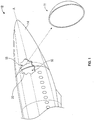
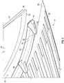
- the disclosed self-balancing pressure bulkhead may be in the form of a disk or a dome, or be dome-shaped, and shaped for placement inside a vehicle, which in an embodiment may be aircraft 12, for example in the fuselage 14 of the aircraft, to separate a pressurized fuselage interior 16 (e.g., a pressurized cabin) from an unpressurized fuselage interior 18.
- a vehicle which in an embodiment may be aircraft 12, for example in the fuselage 14 of the aircraft, to separate a pressurized fuselage interior 16 (e.g., a pressurized cabin) from an unpressurized fuselage interior 18.
- Other types of vehicles may employ the bulkhead 11, such as spacecraft, reentry vehicles, orbiting space stations, land vehicles, and marine vehicles such as submarines.
- Pressure bulkhead 11 may be attached to fuselage skin 20 such that the pressure bulkhead does not shift along fuselage longitudinal axis A of the aircraft 12.
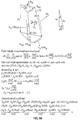
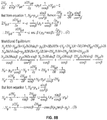
- N ⁇ ⁇ is a shear stress resultant (N/m);
- p n , p ⁇ , p ⁇ are distributed surface loadings in the normal, circumferential and meridional directions (N/m 2 ) respectively;
- R is radius of a theoretical barrel / cylinder ( m ); and
- ⁇ is the angle of spread.
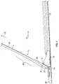
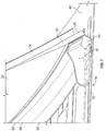
- the pressure bulkhead 11 includes a bulkhead wall 24 having a radially inner disk 26 and a radially outer compression ring 28, the outer compression ring being reinforced to balance meridional and hoop stresses sustained by the bulkhead wall in response to a pressure differential across the pressure bulkhead.
- the radially inner disk 26 may be unitary with the outer compression ring 28 and/or made of the same material as the outer compression ring.
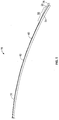
- the radially inner disk 26 has a first thickness y, and the outer compression ring 28 has a second thickness z greater than the first thickness y.
- the thickness of the radially inner disk 26 tapers from an outer periphery 30 adjacent the outer compression ring 28 to a center 32 of the pressure bulkhead 11.
- the taper:distance ramp may be from about 1:5 to about 1:100.
- the bulkhead wall 24, that is, the radially inner disk 26 and the outer compression ring 28, may be made of carbon fiber reinforced plastic (CFRP).
- the taper:distance ramp for a CFRP bulkhead wall may be from about 1:10 to about 1:100.
- the bulkhead wall 24, that is, the radially inner disk 26 and the outer compression ring 28, may be made of a metal, for example, aluminum, titanium, or an aluminum alloy.
- the taper:distance ramp for a metal bulkhead wall may be from about 1:5 to about 1:10. In an embodiment, the ramp may be from a step function to a ramp from 1:1 to 1:100.
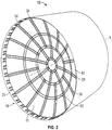
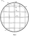
- the pressure bulkhead 11 further includes a plurality of stiffeners 34 attached to the bulkhead wall 26 and extending in a radial direction, for example, a meridional direction, from center 32 toward the outer compression ring 28.
- the stiffeners 34 may be evenly spaced about the bulkhead wall 26 in a spoke-like fashion as shown in Fig. 3 , or in embodiments may be unevenly spaced.
- the plurality of stiffeners 34 include a shorter stiffener 36 a and a longer stiffener 38.
- the bulkhead 11 may include one or more tear straps and/or reinforcement regions , for example, annular tear straps 40 attached to the bulkhead wall 24 (see Fig. 2 ). Stiffeners 34 and annular tear strips 40 may form a plurality of tear regions 42.
- the reinforcement regions may be of any configuration, dimension and/or orientation along the bulkhead wall, for example, those known to one of skill in the art as polar or Cartesian regions,
- the pressure bulkhead 11 may include an attachment mechanism in the form of an attachment ring 44 attached to the outer compression ring 28.
- the attachment of the bulkhead wall 24 to the attachment ring 44 may be by means such as by an adhesive, by a plurality of screws (not shown) spaced about the periphery of the bulkhead wall 24, or by rivets (not shown) spaced about the periphery of the bulkhead wall, and the like.
- the bulkhead 11 may further comprise a plurality of clips 46 configured to attach the attachment ring 44 to a wall 48 of, for example, an aircraft fuselage 14.
- the wall 48 may be the skin 20 of an aircraft.
- the clips 46 may be attached to the skin 20 of the aircraft by, for example, bolting the clips to the skin.
- the pressure bulkhead 11 includes a bulkhead wall 24 having a radially inner disk 26 made of an isotropic carbon fiber reinforced plastic laminate, and an outer compression ring 28 made of an orthotropic carbon fiber reinforced plastic laminate attached to and extending about a periphery 30 of the radially inner disk 26.
- the outer compression ring 28 is selected to be of sufficient strength to balance meridional and hoop stresses sustained by the dome-shaped bulkhead wall 24 in response to a pressure load applied to the bulkhead wall, such as a pressure differential across the bulkhead wall.
- a taper region 56 of radially inner disk 26 extending from periphery 30 toward center 32 may include isotropic carbon fiber reinforced plastic laminate and/or orthotropic carbon fiber reinforced plastic laminate.
- the radially inner disk 26 and/or compression ring may be made of an isotropic carbon fiber reinforced plastic laminate and/or an orthotropic carbon fiber reinforced plastic laminate and/or a similar and CFRP-compatible material.
- the term "similar” may mean, material sufficient to provide performance at least substantially equivalent to an isotropic carbon fiber reinforced plastic laminate as measured by stressing the material in normal, circumferential and meridional directions along the bulkhead wall.
- the term "compatible” may mean one or more materials that may be laminated with CFRP without disintegration. For example, a poly-paraphenylene terephthalamide-based material may be used.
- Kevlar® poly-paraphenylene terephthalamides include Kevlar® K-29, Kevlar® K49, Kevlar® K100, Kevlar® K119, Kevlar® K129, Kevlar® AP, Kevlar® XP and/or Kevlar® KM2.
- the inner disk and compression ring may be unitary. By the term unitary is meant that the disk and compression ring are not seamed, joined, or welded together thus forming a joint between the disk and the compression ring.
- the disk and ring may be made of different laminate types or materials, but in the method of production, both are formed together in the same laminating process.
- the terms "isotropic carbon reinforced plastic laminate” and "orthotropic carbon reinforced plastic laminate” may be known to a person of ordinary skill in the art and such laminates may be constructed according to known methods.
- an orthotropic carbon reinforced plastic laminate may include laminates preferentially oriented along a circumferential, or hoop, stress resultant to balance such pressure-load stresses. With reference to Fig. 8 , normal, circumferential (hoop), and meridional resultants calculated from p n , p ⁇ , p ⁇ are used to determine sufficient laminate strengths to react or oppose such resultants across the entire bulkhead 11. Such calculations may be known to a person of skill in the art of mechanical stress modeling.
- a pressure bulkhead 11 includes a bulkhead wall 24 having a radially inner disk 26 made of metal and having a first thickness y, and a compression ring 28 made of metal attached to and extending about a periphery 30 of the inner disk .
- the compression ring has a second thickness z greater than the first thickness y and sufficient to balance meridional and hoop stresses sustained by the bulkhead wall 24 in response to a pressure load applied to the bulkhead wall.
- the metal may be aluminum, titanium, a mixture thereof, or an alloy of either or both aluminum and titanium.
- a vehicle 12 having a fuselage 14 enclosed by a skin 20; and a pressure bulkhead 11 attached to the skin, about a periphery 30 of the outer compression ring 28.
- the vehicle 12 may be one of an aircraft, a spacecraft, a marine vessel, and a land vehicle.
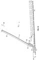
- the periphery 30 of the bulkhead wall 24 may comprise an attachment ring 44 having a radially inner band 50 and a radially outer band 52.
- the attachment ring 44 may be shaped to form a concave surface 54 oriented toward a non-pressurized section 18 of the vehicle fuselage 14.
- the radially outer band 52 may be attached to the skin 20 of the vehicle fuselage 14.
- the radially inner band 50 may be attached to the compression ring 28.
- a method of mounting a pressure bulkhead 11 in a vehicle includes affixing to a fuselage skin 20 of the aircraft an attachment ring 44 having an inner band 50 and an outer band 52 defining a concave surface 54 such that the concave surface 54 is directed toward a non-pressurized section 18 of the aircraft when the aircraft fuselage is under a pressure load; and attaching a periphery 30 of a bulkhead wall 24 to the attachment ring 44, the bulkhead wall 24 having a radially inner disk 26 and a radially outer compression ring 28, the inner disk 26 and outer compression ring 28 being made of the same material, the material being one of carbon fiber reinforced plastic and/or metal, the outer compression ring 28 being of sufficient strength to balance meridional and hoop stresses sustained by the bulkhead wall 24 in response to a pressure load applied to the bulkhead wall 24.
- the attachment ring 44 and/or the clip 46 is made of one of carbon fiber reinforced plastic and/or metal.
- the installing may further comprise a plurality of clips 46 on the concave surface 54 which clips 46 are configured to fix the attachment ring 44 to the skin 48.
- the bulkhead wall 24 may be attached to the attachment ring 44 by mounting the periphery 30 and/or the compression ring 28 on the concave surface 54, that is, between the attachment ring 44 and the clip 46.
- the bulkhead 11 described herein provides a lightweight alternative to conventional pressure bulkheads.
- the compression ring 28 By providing a relatively strong compression ring 28 that is connected to a relatively weaker, and thinner, radially inner disk 26, the compression ring provides resistance to the hoop stress imposed by pressure differential across the surface of the radially inner disk.
- the outer compression ring 28 may be made of the same material as the radially inner disk 26, such as CFRP, in which case the outer compression ring may be relatively thick and the radially inner disk tapers in thickness radially inward to the center of the radially inner disk.
- the pressure bulkhead 11 includes bulkhead wall 56 of substantially uniform thickness from center 58 to periphery 60.
- the pressure bulkhead 11 further includes a plurality of stiffeners 62 attached to the bulkhead wall 56 in a Cartesian configuration.
- an attachment mechanism in the form of one or more doubler rings 66, 68 may be in contact with bulkhead wall 56 and a structure to join the bulkhead wall 56 to the skin 48.
- the one or more doubler rings 66, 68 may contact the bulkhead wall on either side of bulkhead wall 56 or on one side of the bulkhead wall 56.
- the one or more doubler rings 66, 68 may be of the same or of different size. In an embodiment, two or more doubler rings may be placed on both sides of the bulkhead wall 56.
- the bulkhead wall may be made of any suitable material, for example, CFRP and/or metal.
- the doubler ring may be made of any suitable material, for example CFRP and/or metal.
- the one or more doubler rings 66, 68 may be attached to attachment ring 70.
- Attachment ring 70 may be shaped to form a concave surface oriented toward a non-pressurized section 18 of the vehicle fuselage 14 and the attachment ring 70 may be attached to the wall 48.
- the bulkhead 11 may further comprise a plurality of clips 72 configured to attach the attachment ring 70 to wall 48 of, for example, an aircraft fuselage 14.
- the wall 48 may be the skin 20 of an aircraft.
- the clips 72 may be attached to the skin 20 of the aircraft by, for example, bolting the clips to the skin.
Landscapes
- Engineering & Computer Science (AREA)
- Mechanical Engineering (AREA)
- Aviation & Aerospace Engineering (AREA)
- Chemical & Material Sciences (AREA)
- Combustion & Propulsion (AREA)
- Transportation (AREA)
- Ocean & Marine Engineering (AREA)
- Pressure Welding/Diffusion-Bonding (AREA)
- Connection Of Plates (AREA)
- Diaphragms And Bellows (AREA)
Claims (11)
- Druckschott (11), das aufweist:eine kuppelförmige Schottwand (24), die eine radial innere Scheibe (26) und einen radial äußeren Kompressionsring (28) hat, wobei der äußere Kompressionsring verstärkt ist, um Meridionalspannungen und Umfangsspannungen, die im Ansprechen auf ein Druckdifferenzial über das Druckschott von der Schottwand aufgenommen werden, auszugleichen; undeine Vielzahl von Versteifungen (34), die an der Schottwand (24) befestigt sind, wobei sich die Vielzahl von Versteifungen in radialer Richtung erstrecken, wobei die Richtung von der Mitte (32) des Druckschotts (11) in Richtung des äußeren Kompressionsrings (28) verläuft;wobei die radial innere Scheibe mit dem äußeren Kompressionsring unitär ist;wobei die radial innere Scheibe eine erste Stärke hat und der Kompressionsring eine zweite Stärke hat, die größer als die erste Stärke ist; undwobei sich die Stärke der radial inneren Scheibe von einem äußeren Umfang nahe des äußeren Kompressionsrings zur Mitte des Druckschotts verjüngt; wobei die Vielzahl von Versteifungen eine kürzere Versteifung (36) und eine längere Versteifung (38) aufweisen.
- Druckschott nach Anspruch 1, wobei die radial innere Scheibe (26) und der äußere Kompressionsring (28) aus karbonfaserverstärktem Kunststoff hergestellt sind.
- Druckschott (11) nach einem der vorhergehenden Ansprüche, das des Weiteren einen Befestigungsmechanismus aufweist, der ausgewählt wird aus einem Befestigungsring (44), der an dem äußeren Kompressionsring (28) befestigt ist, und einem oder mehreren Dopplerringen (66, 68), die an der Schottwand befestigt sind.
- Druckschott (11) nach Anspruch 3, das des Weiteren eine Vielzahl von Klammern (46) aufweist, die dazu konfiguriert sind, den Befestigungsring (44) an einer Wand (48) zu befestigen.
- Druckschott (11) nach Anspruch 4, wobei die Wand (48) eine Haut (20) eines Flugzeugs (12) ist.
- Druckschott (11) nach einem der vorhergehenden Ansprüche, wobei die radial innere Scheibe (26) und der radiale Kompressionsring (28) aus dem gleichen Material hergestellt sind.
- Druckschott (11) nach einem der Ansprüche 1 bis 5, wobei die radial innere Scheibe (26) aus einem isotropen karbonfaserverstärkten Kunststofflaminat hergestellt ist, und wobei der äußere Kompressionsring (28) aus einem orthotropen karbonfaserverstärkten Kunststofflaminat hergestellt ist.
- Verfahren zum Anbringen eines Druckschotts (11) in einem Flugzeug (12), wobei das Verfahren aufweist:Befestigen eines Befestigungsrings (44), der ein inneres Band (50) und ein äußeres Band (52) hat, die eine konkave Oberfläche definieren, an einer Rumpfhaut (20) des Flugzeugs derart, dass die konkave Oberfläche zu einem nicht mit Druck beaufschlagten Abschnitt (18) des Flugzeugs hin gerichtet ist, wenn die Flugzeugrumpfhaut unter einer Druckbelastung steht; undBefestigen eines äußeren Umfangs (30) einer Schottwand (24) an dem Befestigungsring, wobei die Schottwand eine radial innere Scheibe (26) und einen radial äußeren Kompressionsring (28) hat, wobei der äußere Kompressionsring ausreichend stark ist, um Meridionalspannungen und Umfangsspannungen, die im Ansprechen auf eine auf die Schottwand ausgeübte Drucklast von der Schottwand aufgenommen werden, ausgleichen zu können;wobei die radial innere Scheibe eine erste Stärke hat und der Kompressionsring eine zweite Stärke hat, die größer als die erste Stärke ist;wobei sich die Stärke der radial inneren Scheibe von einem äußeren Umfang nahe des äußeren Kompressionsrings zur Mitte des Druckschotts verjüngt; undwobei das Druckschott eine Vielzahl von Versteifungen (34) aufweist, die an der Schottwand (24) befestigt sind, wobei sich die Vielzahl von Versteifungen in radialer Richtung erstrecken, wobei die Richtung von der Mitte (232) des Druckschotts (11) in Richtung des äußeren Kompressionsrings (28) geht; wobei die Vielzahl von Versteifungen eine kürzere Versteifung (36) und eine längere Versteifung (38) aufweisen.
- Verfahren nach Anspruch 8, wobei der Befestigungsring (44) aus einem von karbonfaserverstärktem Kunststoff und Metall hergestellt ist.
- Verfahren nach Anspruch 9, das des Weiteren das Anbringen einer Vielzahl von Klammern (46) an der konkaven Oberfläche (54) aufweist, wobei die Klammern dazu konfiguriert sind, den Befestigungsring (44) an der Haut (20) zu befestigen.
- Verfahren nach Anspruch 10, das des Weiteren das Anbringen des Kompressionsrings (28) zwischen den Klammern (46) und der konkaven Oberfläche (54) aufweist.
Applications Claiming Priority (1)
| Application Number | Priority Date | Filing Date | Title |
|---|---|---|---|
| US13/915,994 US10189578B2 (en) | 2013-06-12 | 2013-06-12 | Self-balancing pressure bulkhead |
Publications (2)
| Publication Number | Publication Date |
|---|---|
| EP2813425A1 EP2813425A1 (de) | 2014-12-17 |
| EP2813425B1 true EP2813425B1 (de) | 2020-10-28 |
Family
ID=50771158
Family Applications (1)
| Application Number | Title | Priority Date | Filing Date |
|---|---|---|---|
| EP14169530.4A Active EP2813425B1 (de) | 2013-06-12 | 2014-05-22 | Selbstausgleichendes Druckschott |
Country Status (6)
| Country | Link |
|---|---|
| US (2) | US10189578B2 (de) |
| EP (1) | EP2813425B1 (de) |
| JP (1) | JP6502622B2 (de) |
| CN (1) | CN104229117B (de) |
| BR (1) | BR102014014075B1 (de) |
| ES (1) | ES2846733T3 (de) |
Cited By (1)
| Publication number | Priority date | Publication date | Assignee | Title |
|---|---|---|---|---|
| EP3257662B1 (de) * | 2016-05-16 | 2022-07-06 | The Boeing Company | Verbundwerkstoff-druckschott |
Families Citing this family (18)
| Publication number | Priority date | Publication date | Assignee | Title |
|---|---|---|---|---|
| DE102013102812B4 (de) * | 2013-03-19 | 2017-01-26 | Airbus Operations Gmbh | Rumpfstruktur für ein Verkehrsmittel, Verkehrsmittel und Verfahren zum Herstellen einer Rumpfstruktur für ein Verkehrsmittel |
| US10189578B2 (en) * | 2013-06-12 | 2019-01-29 | The Boeing Company | Self-balancing pressure bulkhead |
| DE102013114391A1 (de) * | 2013-12-18 | 2015-06-18 | Airbus Operations Gmbh | Druckrumpf eines Flugzeuges, umfassend ein bewegbar relativ zur Rumpfstruktur befestigtes Druckschott |
| EP3064429A1 (de) * | 2015-03-06 | 2016-09-07 | Airbus Operations GmbH | Druckschott für unrunde Rumpfsektion |
| ES2709346T3 (es) * | 2015-03-06 | 2019-04-16 | Airbus Operations Gmbh | Mamparo de presión trasero extendido |
| DE102015205934B3 (de) * | 2015-04-01 | 2016-09-22 | Airbus Operations Gmbh | Druckschott und Verfahren zur Herstellung eines Druckschotts |
| DE102016002844B3 (de) * | 2016-03-10 | 2017-08-10 | Premium Aerotec Gmbh | Strukturbauteil, Verfahren zur Herstellung eines Strukturbauteils, Druckrumpf für ein Fahrzeug mit Strukturbauteil |
| US10173765B2 (en) * | 2016-04-07 | 2019-01-08 | The Boeing Company | Pressure bulkhead apparatus |
| US10926857B2 (en) * | 2016-06-17 | 2021-02-23 | The Boeing Company | Pressurized bulkhead |
| CN107554748A (zh) * | 2016-07-01 | 2018-01-09 | 陕西飞机工业(集团)有限公司 | 一种飞机尾段气密端框 |
| JP6142063B1 (ja) * | 2016-09-29 | 2017-06-07 | 一夫 有▲吉▼ | ジエット機の着脱自在圧力隔壁の後部支持装置 |
| US10926858B2 (en) * | 2017-08-07 | 2021-02-23 | The Boeing Company | Pressure bulkhead system |
| EP3533706B1 (de) * | 2018-03-02 | 2023-02-15 | Premium AEROTEC GmbH | Druckschott für ein luftfahrzeug |
| US11946413B2 (en) * | 2019-07-29 | 2024-04-02 | The Boeing Company | Inlet bulkheads for large diameter aircraft engines |
| ES2909500T3 (es) * | 2019-07-30 | 2022-05-06 | Airbus Sas | Mamparo de presión |
| US11420718B2 (en) * | 2020-03-27 | 2022-08-23 | The Boeing Company | Aircraft tail assembly |
| CN113665842A (zh) * | 2021-08-17 | 2021-11-19 | 中国商用飞机有限责任公司 | 试验加载装置 |
| JP7307843B1 (ja) | 2022-08-24 | 2023-07-12 | トーホーテック株式会社 | チタン製のタンク、および当該タンクを備えるタンクローリー |
Family Cites Families (72)
| Publication number | Priority date | Publication date | Assignee | Title |
|---|---|---|---|---|
| US3663344A (en) * | 1970-12-31 | 1972-05-16 | Kimberly Clark Co | Orthotropic fiber-reinforced thermoplastic film and method of manufacture |
| DE3534719A1 (de) * | 1985-09-28 | 1987-04-02 | Messerschmitt Boelkow Blohm | Druckwand fuer einen unter inneren ueberdruck setzbaren rumpf eines luftfahrzeuges |
| JPS62199591A (ja) * | 1986-02-28 | 1987-09-03 | 三菱重工業株式会社 | 隔壁 |
| JPS62203899A (ja) * | 1986-03-02 | 1987-09-08 | 有吉 一夫 | 航空機胴体尾部の圧力隔壁保持構造 |
| JPS63112744A (ja) * | 1986-10-24 | 1988-05-17 | 住友化学工業株式会社 | 織機用綜絖枠の外枠ステ− |
| US4867357A (en) * | 1987-12-21 | 1989-09-19 | General Dynamics Corp., Pomona Division | Jettisonable protective cover device |
| US5171510A (en) * | 1988-06-08 | 1992-12-15 | Aerospatiale Societe Nationale Industrielle | Method of producing a frame made of a composite material, especially for the fuselage of an aircraft |
| FR2632604B1 (fr) * | 1988-06-08 | 1991-07-12 | Aerospatiale | Cadre en materiau composite notamment pour fuselage d'aeronef, et son procede de fabrication |
| GB8821222D0 (en) * | 1988-09-09 | 1988-12-14 | British Aerospace | Double curvature structures by superplastic forming & diffusion bonding |
| DE3923871A1 (de) * | 1989-02-28 | 1991-01-31 | Dornier Luftfahrt | Druckspant |
| US5125600A (en) * | 1991-06-03 | 1992-06-30 | Rockwell International Corporation | Removable radome cover |
| US5167386A (en) * | 1992-01-21 | 1992-12-01 | Rockwell International Corporation | Pyrotechnic removal of a radome cover |
| JP3124984B2 (ja) | 1993-01-14 | 2001-01-15 | 四国電力株式会社 | 繊維強化複合材製回転体とその製造方法 |
| US5743492A (en) * | 1994-02-18 | 1998-04-28 | Lockheed Martin Corporation | Payload housing and assembly joint for a launch vehicle |
| JPH07291197A (ja) * | 1994-04-22 | 1995-11-07 | Mitsubishi Heavy Ind Ltd | サンドイッチ球殻構造物及びその製作方法 |
| US5820077A (en) * | 1995-09-26 | 1998-10-13 | Mcdonnell Douglas Technologies, Inc. | Aircraft radome and integral attaching structure |
| DE19652172C2 (de) * | 1996-12-14 | 1998-09-17 | Daimler Benz Aerospace Airbus | Druckspant für einen Flugzeugrumpf |
| JPH10325415A (ja) | 1997-03-28 | 1998-12-08 | Seiko Epson Corp | 超電導磁気軸受装置の磁石部補強構造 |
| AT405813B (de) * | 1997-11-10 | 1999-11-25 | Fischer Adv Components Gmbh | Druckspant, insbesondere für flugzeuge |
| US6213426B1 (en) * | 1999-07-09 | 2001-04-10 | The Boeing Company | Monolithic structure with redundant load paths |
| JP3997047B2 (ja) * | 2000-05-01 | 2007-10-24 | 本田技研工業株式会社 | スキンと圧力隔壁の接合構造体 |
| US6435786B1 (en) * | 2000-07-24 | 2002-08-20 | The Boeing Company | Main deck cargo barrier net configuration |
| IL139891A (en) * | 2000-11-23 | 2004-07-25 | Rafael Armament Dev Authority | Protection element disconnected |
| DE10111896B8 (de) * | 2001-03-13 | 2012-06-06 | Eads Space Transportation Gmbh | Metallischer Ring für die Verbindung zweier rotationssymmetrischer Strukturteile |
| US20020178583A1 (en) * | 2001-03-14 | 2002-12-05 | Holman Wrenn P. | Modular monolithic bulkhead panel |
| US20040035979A1 (en) * | 2002-08-23 | 2004-02-26 | Mccoskey William Robert | Integrally stiffened axial load carrying skin panels for primary aircraft structure and closed loop manufacturing methods for making the same |
| DE10240040A1 (de) * | 2002-08-27 | 2004-03-11 | BODENSEEWERK GERäTETECHNIK GMBH | Lenkflugkörper mit abwerfbarer Schutzkappe |
| EP1589611B1 (de) * | 2003-01-30 | 2008-07-09 | Sumitomo Electric Industries, Ltd. | Linsenantennensystem |
| US7082878B2 (en) * | 2003-07-01 | 2006-08-01 | Raytheon Company | Missile with multiple nosecones |
| DE10343627B4 (de) * | 2003-09-20 | 2014-03-06 | Eads Deutschland Gmbh | Verschlusselement für einen Bereich der Außenhaut eines Luftfahrzeugs |
| FR2864020B1 (fr) * | 2003-12-19 | 2006-02-10 | Airbus France | Nez d'avion avec bouclier |
| FR2872127B1 (fr) * | 2004-06-29 | 2006-08-11 | Airbus France Sas | Dispositif et procede de fixation d'un radome d'aeronef |
| US7699260B2 (en) * | 2005-01-14 | 2010-04-20 | Hughey Electricopter Corporation | Vertical takeoff and landing aircraft using a redundant array of independent rotors |
| US7669796B2 (en) * | 2005-05-24 | 2010-03-02 | Daniel Nachbar | Hoop stress reduction in a buoyant airship |
| WO2007020910A1 (ja) * | 2005-08-18 | 2007-02-22 | Teijin Techno Products Limited | 等方性の繊維強化熱可塑性樹脂シートとその製造方法並びに成形板 |
| US7766277B2 (en) * | 2006-01-19 | 2010-08-03 | The Boeing Company | Deformable forward pressure bulkhead for an aircraft |
| US7997529B2 (en) * | 2006-01-19 | 2011-08-16 | The Boeing Company | Compliant panel for aircraft |
| NO327766B1 (no) | 2006-06-19 | 2009-09-21 | Tanker Engineering As | Sylindrisk tank og fremgangsmate for fremstilling av denne |
| DE102006029231B4 (de) * | 2006-06-26 | 2013-09-26 | Airbus Operations Gmbh | Druckschott für einen Rumpf für die Luft- und Raumfahrt |
| US20080179459A1 (en) * | 2007-01-30 | 2008-07-31 | Airbus Espana, S.L. | Pressure bulkhead made of composite material for an aircraft |
| EP2098448A4 (de) | 2006-11-29 | 2012-08-08 | Airbus Operations Sl | Flugzeugverbunddruckschott |
| JP2008207522A (ja) * | 2007-02-28 | 2008-09-11 | Toray Ind Inc | 炭素繊維強化プラスチック製支持バーおよびその成形方法 |
| FR2917369B1 (fr) * | 2007-06-15 | 2009-08-07 | Airbus France Sas | Case de train d'atterrissage a encombrement reduit |
| DE102007044388B4 (de) * | 2007-09-18 | 2012-08-02 | Airbus Operations Gmbh | Druckschott und Verfahren zum Unterteilen eines Luft- oder Raumfahrzeugs |
| DE102007052140B4 (de) | 2007-10-31 | 2012-10-25 | Airbus Operations Gmbh | Struktur, insbesondere Rumpfstruktur eines Luft- oder Raumfahrzeugs |
| IL188524A0 (en) * | 2008-01-01 | 2008-11-03 | Izhack Zubalsky | Imaging system and method |
| IL189089A0 (en) * | 2008-01-28 | 2008-08-07 | Rafael Advanced Defense Sys | Apparatus and method for splitting and removing a shroud from an airborne vehicle |
| DE102008040213B4 (de) * | 2008-07-07 | 2011-08-25 | Airbus Operations GmbH, 21129 | Verfahren zur Montage eines kalottenförmigen Druckschotts in einer Hecksektion eines Flugzeugs sowie Vorrichtung zur Durchführung des Verfahrens |
| CA2638150C (en) * | 2008-07-24 | 2012-03-27 | Sunopta Bioprocess Inc. | Method and apparatus for conveying a cellulosic feedstock |
| DE102008041173A1 (de) * | 2008-08-12 | 2010-03-04 | Airbus Deutschland Gmbh | Rumpfsektion mit integralem Druckschott sowie Rumpfschale mit einer derartigen Rumpfsektion |
| US20100155533A1 (en) * | 2008-12-23 | 2010-06-24 | Spirit Aerosystems, Inc. | Composite forward pressure bulkhead |
| FR2940959B1 (fr) | 2009-01-15 | 2011-03-11 | Airbus France | Partie avant d'aeronef comportant une cloison concave separant une zone de radome non pressurisee et une zone pressurisee |
| US8322655B1 (en) * | 2009-03-25 | 2012-12-04 | The Boeing Company | Twin-boom empennage |
| ES2347122B1 (es) | 2009-03-31 | 2011-08-11 | Airbus Operations, S.L. | Estructura de ensamblaje del mamparo de presion de una aeronave. |
| DE102009035265B4 (de) * | 2009-07-29 | 2013-06-06 | Airbus Operations Gmbh | Druckrumpf eines Luft- oder Raumfahrzeuges mit Druckkalotte |
| US8061656B1 (en) * | 2009-09-22 | 2011-11-22 | The United States Of America As Represented By The Secretary Of The Navy | Hinge apparatus with an actuatable assembly |
| DE102009049007A1 (de) * | 2009-10-09 | 2011-04-21 | Airbus Operations Gmbh | Druckrumpf eines Flugzeuges mit heckseitiger Druckkalotte |
| US8519312B1 (en) * | 2010-01-29 | 2013-08-27 | Raytheon Company | Missile with shroud that separates in flight |
| FR2966423B1 (fr) * | 2010-10-26 | 2012-12-07 | Airbus Operations Sas | Encadrement d'une ouverture realisee dans un panneau d'aeronef et procede de montage |
| CA2817200C (en) * | 2010-11-16 | 2019-01-08 | The Nordam Group, Inc. | Hybrid frame co-mold manufacture |
| US8497457B2 (en) * | 2010-12-07 | 2013-07-30 | Raytheon Company | Flight vehicles with improved pointing devices for optical systems |
| US8497456B2 (en) * | 2011-03-30 | 2013-07-30 | Raytheon Company | Guided munitions including interlocking dome covers and methods for equipping guided munitions with the same |
| US9054409B2 (en) * | 2011-07-21 | 2015-06-09 | Harris Corporation | Systems for positioning reflectors, such as passive reflectors |
| EP2787241A4 (de) | 2011-11-28 | 2015-07-08 | Teijin Ltd | Schlagabsorbierendes element |
| US8931738B2 (en) * | 2012-02-21 | 2015-01-13 | Raytheon Company | Releasable radome cover |
| US8870118B2 (en) * | 2012-05-07 | 2014-10-28 | The Boeing Company | Method and systems for use in assembling a fuselage |
| US8960606B2 (en) * | 2012-10-31 | 2015-02-24 | The Boeing Company | Circumference splice for joining shell structures |
| FR2999344B1 (fr) * | 2012-12-10 | 2018-04-13 | Airbus Operations | Antenne de radar meteorologique embarque pour aeronef et aeronef associe |
| US10189578B2 (en) * | 2013-06-12 | 2019-01-29 | The Boeing Company | Self-balancing pressure bulkhead |
| DE102013224233A1 (de) * | 2013-11-27 | 2015-05-28 | Airbus Operations Gmbh | Druckschott für ein Flugzeug und Vorrichtung sowie Verfahren zur Herstellung eines Flugzeugstrukturbauteils |
| US9399507B2 (en) * | 2014-01-22 | 2016-07-26 | The Boeing Company | Joints between a composite skin and a load-bearing component and methods of forming same |
| US9776704B1 (en) * | 2016-05-16 | 2017-10-03 | The Boeing Company | Composite pressure bulkhead |
-
2013
- 2013-06-12 US US13/915,994 patent/US10189578B2/en active Active
-
2014
- 2014-05-22 EP EP14169530.4A patent/EP2813425B1/de active Active
- 2014-05-22 ES ES14169530T patent/ES2846733T3/es active Active
- 2014-06-06 JP JP2014117326A patent/JP6502622B2/ja active Active
- 2014-06-10 BR BR102014014075-1A patent/BR102014014075B1/pt active IP Right Grant
- 2014-06-12 CN CN201410260717.XA patent/CN104229117B/zh active Active
-
2018
- 2018-12-05 US US16/210,430 patent/US10464691B2/en active Active
Non-Patent Citations (1)
| Title |
|---|
| None * |
Cited By (1)
| Publication number | Priority date | Publication date | Assignee | Title |
|---|---|---|---|---|
| EP3257662B1 (de) * | 2016-05-16 | 2022-07-06 | The Boeing Company | Verbundwerkstoff-druckschott |
Also Published As
| Publication number | Publication date |
|---|---|
| US20190106222A1 (en) | 2019-04-11 |
| JP2015006872A (ja) | 2015-01-15 |
| CN104229117B (zh) | 2019-08-16 |
| BR102014014075B1 (pt) | 2021-11-30 |
| BR102014014075A2 (pt) | 2015-08-11 |
| JP6502622B2 (ja) | 2019-04-17 |
| US20140370227A1 (en) | 2014-12-18 |
| US10189578B2 (en) | 2019-01-29 |
| EP2813425A1 (de) | 2014-12-17 |
| CN104229117A (zh) | 2014-12-24 |
| ES2846733T3 (es) | 2021-07-29 |
| US10464691B2 (en) | 2019-11-05 |
Similar Documents
| Publication | Publication Date | Title |
|---|---|---|
| EP2813425B1 (de) | Selbstausgleichendes Druckschott | |
| US8398021B2 (en) | Compliant crown panel for an aircraft | |
| EP2032431B1 (de) | Druckschott für einen rumpf für die luft- und raumfahrt | |
| US20080179459A1 (en) | Pressure bulkhead made of composite material for an aircraft | |
| EP1794050B1 (de) | Spleissverbindungen für zusammengesetzte flugzeugrümpfe und andere strukturen | |
| US6648273B2 (en) | Light weight and high strength fuselage | |
| US8016234B2 (en) | Airframe structure of an aircraft or spacecraft | |
| EP2730495B1 (de) | Mantelstruktur für einen Rumpf | |
| EP2457821A2 (de) | Nachgiebige Platte für ein Flugzeug | |
| US10384759B2 (en) | Pressure bulkhead for an aircraft fuselage | |
| US8181909B2 (en) | Pressure bulkhead for aircraft | |
| US5899412A (en) | Aircraft pressure containment assembly module | |
| EP2098448A1 (de) | Flugzeugverbunddruckschott | |
| JPH02234897A (ja) | 圧力隔壁 | |
| EP3243740B1 (de) | Druckschottsystem | |
| US10501163B2 (en) | Pressure bulkhead for an aircraft fuselage, and an aircraft comprising such a pressure bulkhead | |
| US10099766B2 (en) | Pressurized airplane fuselage, comprising a pressure bulkhead | |
| RU197021U1 (ru) | Силовая конструкция корпуса космического аппарата | |
| CN112298522A (zh) | 用于飞行器的后部压力隔板、飞行器的后部机身和飞行器 | |
| US11312470B2 (en) | Pressure bulkhead for an aircraft |
Legal Events
| Date | Code | Title | Description |
|---|---|---|---|
| 17P | Request for examination filed |
Effective date: 20140522 |
|
| AK | Designated contracting states |
Kind code of ref document: A1 Designated state(s): AL AT BE BG CH CY CZ DE DK EE ES FI FR GB GR HR HU IE IS IT LI LT LU LV MC MK MT NL NO PL PT RO RS SE SI SK SM TR |
|
| AX | Request for extension of the european patent |
Extension state: BA ME |
|
| PUAI | Public reference made under article 153(3) epc to a published international application that has entered the european phase |
Free format text: ORIGINAL CODE: 0009012 |
|
| 17Q | First examination report despatched |
Effective date: 20160824 |
|
| STAA | Information on the status of an ep patent application or granted ep patent |
Free format text: STATUS: EXAMINATION IS IN PROGRESS |
|
| GRAP | Despatch of communication of intention to grant a patent |
Free format text: ORIGINAL CODE: EPIDOSNIGR1 |
|
| STAA | Information on the status of an ep patent application or granted ep patent |
Free format text: STATUS: GRANT OF PATENT IS INTENDED |
|
| INTG | Intention to grant announced |
Effective date: 20200403 |
|
| GRAJ | Information related to disapproval of communication of intention to grant by the applicant or resumption of examination proceedings by the epo deleted |
Free format text: ORIGINAL CODE: EPIDOSDIGR1 |
|
| STAA | Information on the status of an ep patent application or granted ep patent |
Free format text: STATUS: EXAMINATION IS IN PROGRESS |
|
| INTC | Intention to grant announced (deleted) | ||
| GRAR | Information related to intention to grant a patent recorded |
Free format text: ORIGINAL CODE: EPIDOSNIGR71 |
|
| GRAS | Grant fee paid |
Free format text: ORIGINAL CODE: EPIDOSNIGR3 |
|
| STAA | Information on the status of an ep patent application or granted ep patent |
Free format text: STATUS: GRANT OF PATENT IS INTENDED |
|
| GRAA | (expected) grant |
Free format text: ORIGINAL CODE: 0009210 |
|
| STAA | Information on the status of an ep patent application or granted ep patent |
Free format text: STATUS: THE PATENT HAS BEEN GRANTED |
|
| INTG | Intention to grant announced |
Effective date: 20200917 |
|
| AK | Designated contracting states |
Kind code of ref document: B1 Designated state(s): AL AT BE BG CH CY CZ DE DK EE ES FI FR GB GR HR HU IE IS IT LI LT LU LV MC MK MT NL NO PL PT RO RS SE SI SK SM TR |
|
| REG | Reference to a national code |
Ref country code: GB Ref legal event code: FG4D |
|
| REG | Reference to a national code |
Ref country code: CH Ref legal event code: EP |
|
| REG | Reference to a national code |
Ref country code: DE Ref legal event code: R096 Ref document number: 602014071631 Country of ref document: DE |
|
| REG | Reference to a national code |
Ref country code: AT Ref legal event code: REF Ref document number: 1327962 Country of ref document: AT Kind code of ref document: T Effective date: 20201115 |
|
| REG | Reference to a national code |
Ref country code: IE Ref legal event code: FG4D |
|
| REG | Reference to a national code |
Ref country code: AT Ref legal event code: MK05 Ref document number: 1327962 Country of ref document: AT Kind code of ref document: T Effective date: 20201028 |
|
| REG | Reference to a national code |
Ref country code: NL Ref legal event code: MP Effective date: 20201028 |
|
| PG25 | Lapsed in a contracting state [announced via postgrant information from national office to epo] |
Ref country code: RS Free format text: LAPSE BECAUSE OF FAILURE TO SUBMIT A TRANSLATION OF THE DESCRIPTION OR TO PAY THE FEE WITHIN THE PRESCRIBED TIME-LIMIT Effective date: 20201028 Ref country code: FI Free format text: LAPSE BECAUSE OF FAILURE TO SUBMIT A TRANSLATION OF THE DESCRIPTION OR TO PAY THE FEE WITHIN THE PRESCRIBED TIME-LIMIT Effective date: 20201028 Ref country code: PT Free format text: LAPSE BECAUSE OF FAILURE TO SUBMIT A TRANSLATION OF THE DESCRIPTION OR TO PAY THE FEE WITHIN THE PRESCRIBED TIME-LIMIT Effective date: 20210301 Ref country code: NL Free format text: LAPSE BECAUSE OF FAILURE TO SUBMIT A TRANSLATION OF THE DESCRIPTION OR TO PAY THE FEE WITHIN THE PRESCRIBED TIME-LIMIT Effective date: 20201028 Ref country code: NO Free format text: LAPSE BECAUSE OF FAILURE TO SUBMIT A TRANSLATION OF THE DESCRIPTION OR TO PAY THE FEE WITHIN THE PRESCRIBED TIME-LIMIT Effective date: 20210128 Ref country code: GR Free format text: LAPSE BECAUSE OF FAILURE TO SUBMIT A TRANSLATION OF THE DESCRIPTION OR TO PAY THE FEE WITHIN THE PRESCRIBED TIME-LIMIT Effective date: 20210129 |
|
| REG | Reference to a national code |
Ref country code: LT Ref legal event code: MG4D |
|
| PG25 | Lapsed in a contracting state [announced via postgrant information from national office to epo] |
Ref country code: PL Free format text: LAPSE BECAUSE OF FAILURE TO SUBMIT A TRANSLATION OF THE DESCRIPTION OR TO PAY THE FEE WITHIN THE PRESCRIBED TIME-LIMIT Effective date: 20201028 Ref country code: SE Free format text: LAPSE BECAUSE OF FAILURE TO SUBMIT A TRANSLATION OF THE DESCRIPTION OR TO PAY THE FEE WITHIN THE PRESCRIBED TIME-LIMIT Effective date: 20201028 Ref country code: LV Free format text: LAPSE BECAUSE OF FAILURE TO SUBMIT A TRANSLATION OF THE DESCRIPTION OR TO PAY THE FEE WITHIN THE PRESCRIBED TIME-LIMIT Effective date: 20201028 Ref country code: IS Free format text: LAPSE BECAUSE OF FAILURE TO SUBMIT A TRANSLATION OF THE DESCRIPTION OR TO PAY THE FEE WITHIN THE PRESCRIBED TIME-LIMIT Effective date: 20210228 Ref country code: AT Free format text: LAPSE BECAUSE OF FAILURE TO SUBMIT A TRANSLATION OF THE DESCRIPTION OR TO PAY THE FEE WITHIN THE PRESCRIBED TIME-LIMIT Effective date: 20201028 Ref country code: BG Free format text: LAPSE BECAUSE OF FAILURE TO SUBMIT A TRANSLATION OF THE DESCRIPTION OR TO PAY THE FEE WITHIN THE PRESCRIBED TIME-LIMIT Effective date: 20210128 |
|
| PG25 | Lapsed in a contracting state [announced via postgrant information from national office to epo] |
Ref country code: HR Free format text: LAPSE BECAUSE OF FAILURE TO SUBMIT A TRANSLATION OF THE DESCRIPTION OR TO PAY THE FEE WITHIN THE PRESCRIBED TIME-LIMIT Effective date: 20201028 |
|
| REG | Reference to a national code |
Ref country code: DE Ref legal event code: R097 Ref document number: 602014071631 Country of ref document: DE Ref country code: ES Ref legal event code: FG2A Ref document number: 2846733 Country of ref document: ES Kind code of ref document: T3 Effective date: 20210729 |
|
| PG25 | Lapsed in a contracting state [announced via postgrant information from national office to epo] |
Ref country code: LT Free format text: LAPSE BECAUSE OF FAILURE TO SUBMIT A TRANSLATION OF THE DESCRIPTION OR TO PAY THE FEE WITHIN THE PRESCRIBED TIME-LIMIT Effective date: 20201028 Ref country code: SK Free format text: LAPSE BECAUSE OF FAILURE TO SUBMIT A TRANSLATION OF THE DESCRIPTION OR TO PAY THE FEE WITHIN THE PRESCRIBED TIME-LIMIT Effective date: 20201028 Ref country code: RO Free format text: LAPSE BECAUSE OF FAILURE TO SUBMIT A TRANSLATION OF THE DESCRIPTION OR TO PAY THE FEE WITHIN THE PRESCRIBED TIME-LIMIT Effective date: 20201028 Ref country code: CZ Free format text: LAPSE BECAUSE OF FAILURE TO SUBMIT A TRANSLATION OF THE DESCRIPTION OR TO PAY THE FEE WITHIN THE PRESCRIBED TIME-LIMIT Effective date: 20201028 Ref country code: EE Free format text: LAPSE BECAUSE OF FAILURE TO SUBMIT A TRANSLATION OF THE DESCRIPTION OR TO PAY THE FEE WITHIN THE PRESCRIBED TIME-LIMIT Effective date: 20201028 Ref country code: SM Free format text: LAPSE BECAUSE OF FAILURE TO SUBMIT A TRANSLATION OF THE DESCRIPTION OR TO PAY THE FEE WITHIN THE PRESCRIBED TIME-LIMIT Effective date: 20201028 |
|
| PG25 | Lapsed in a contracting state [announced via postgrant information from national office to epo] |
Ref country code: DK Free format text: LAPSE BECAUSE OF FAILURE TO SUBMIT A TRANSLATION OF THE DESCRIPTION OR TO PAY THE FEE WITHIN THE PRESCRIBED TIME-LIMIT Effective date: 20201028 |
|
| PLBE | No opposition filed within time limit |
Free format text: ORIGINAL CODE: 0009261 |
|
| STAA | Information on the status of an ep patent application or granted ep patent |
Free format text: STATUS: NO OPPOSITION FILED WITHIN TIME LIMIT |
|
| 26N | No opposition filed |
Effective date: 20210729 |
|
| PG25 | Lapsed in a contracting state [announced via postgrant information from national office to epo] |
Ref country code: AL Free format text: LAPSE BECAUSE OF FAILURE TO SUBMIT A TRANSLATION OF THE DESCRIPTION OR TO PAY THE FEE WITHIN THE PRESCRIBED TIME-LIMIT Effective date: 20201028 |
|
| PG25 | Lapsed in a contracting state [announced via postgrant information from national office to epo] |
Ref country code: SI Free format text: LAPSE BECAUSE OF FAILURE TO SUBMIT A TRANSLATION OF THE DESCRIPTION OR TO PAY THE FEE WITHIN THE PRESCRIBED TIME-LIMIT Effective date: 20201028 |
|
| REG | Reference to a national code |
Ref country code: CH Ref legal event code: PL |
|
| PG25 | Lapsed in a contracting state [announced via postgrant information from national office to epo] |
Ref country code: MC Free format text: LAPSE BECAUSE OF FAILURE TO SUBMIT A TRANSLATION OF THE DESCRIPTION OR TO PAY THE FEE WITHIN THE PRESCRIBED TIME-LIMIT Effective date: 20201028 Ref country code: LI Free format text: LAPSE BECAUSE OF NON-PAYMENT OF DUE FEES Effective date: 20210531 Ref country code: LU Free format text: LAPSE BECAUSE OF NON-PAYMENT OF DUE FEES Effective date: 20210522 Ref country code: CH Free format text: LAPSE BECAUSE OF NON-PAYMENT OF DUE FEES Effective date: 20210531 |
|
| REG | Reference to a national code |
Ref country code: BE Ref legal event code: MM Effective date: 20210531 |
|
| PG25 | Lapsed in a contracting state [announced via postgrant information from national office to epo] |
Ref country code: IE Free format text: LAPSE BECAUSE OF NON-PAYMENT OF DUE FEES Effective date: 20210522 |
|
| PG25 | Lapsed in a contracting state [announced via postgrant information from national office to epo] |
Ref country code: IS Free format text: LAPSE BECAUSE OF FAILURE TO SUBMIT A TRANSLATION OF THE DESCRIPTION OR TO PAY THE FEE WITHIN THE PRESCRIBED TIME-LIMIT Effective date: 20210228 |
|
| PG25 | Lapsed in a contracting state [announced via postgrant information from national office to epo] |
Ref country code: BE Free format text: LAPSE BECAUSE OF NON-PAYMENT OF DUE FEES Effective date: 20210531 |
|
| PG25 | Lapsed in a contracting state [announced via postgrant information from national office to epo] |
Ref country code: HU Free format text: LAPSE BECAUSE OF FAILURE TO SUBMIT A TRANSLATION OF THE DESCRIPTION OR TO PAY THE FEE WITHIN THE PRESCRIBED TIME-LIMIT; INVALID AB INITIO Effective date: 20140522 |
|
| P01 | Opt-out of the competence of the unified patent court (upc) registered |
Effective date: 20230516 |
|
| PG25 | Lapsed in a contracting state [announced via postgrant information from national office to epo] |
Ref country code: CY Free format text: LAPSE BECAUSE OF FAILURE TO SUBMIT A TRANSLATION OF THE DESCRIPTION OR TO PAY THE FEE WITHIN THE PRESCRIBED TIME-LIMIT Effective date: 20201028 |
|
| PGFP | Annual fee paid to national office [announced via postgrant information from national office to epo] |
Ref country code: IT Payment date: 20230519 Year of fee payment: 10 |
|
| PG25 | Lapsed in a contracting state [announced via postgrant information from national office to epo] |
Ref country code: MK Free format text: LAPSE BECAUSE OF FAILURE TO SUBMIT A TRANSLATION OF THE DESCRIPTION OR TO PAY THE FEE WITHIN THE PRESCRIBED TIME-LIMIT Effective date: 20201028 |
|
| PG25 | Lapsed in a contracting state [announced via postgrant information from national office to epo] |
Ref country code: TR Free format text: LAPSE BECAUSE OF FAILURE TO SUBMIT A TRANSLATION OF THE DESCRIPTION OR TO PAY THE FEE WITHIN THE PRESCRIBED TIME-LIMIT Effective date: 20201028 |
|
| PGFP | Annual fee paid to national office [announced via postgrant information from national office to epo] |
Ref country code: GB Payment date: 20240527 Year of fee payment: 11 |
|
| PGFP | Annual fee paid to national office [announced via postgrant information from national office to epo] |
Ref country code: DE Payment date: 20240530 Year of fee payment: 11 |
|
| PGFP | Annual fee paid to national office [announced via postgrant information from national office to epo] |
Ref country code: ES Payment date: 20240603 Year of fee payment: 11 |
|
| PGFP | Annual fee paid to national office [announced via postgrant information from national office to epo] |
Ref country code: FR Payment date: 20240527 Year of fee payment: 11 |