EP2813402A1 - Reinigungssystem, das das Spritzen von Reinigungs- und/oder Enteisungsflüssigkeit auf der Höhe des Scheibenwischerblatts ermöglicht - Google Patents
Reinigungssystem, das das Spritzen von Reinigungs- und/oder Enteisungsflüssigkeit auf der Höhe des Scheibenwischerblatts ermöglicht Download PDFInfo
- Publication number
- EP2813402A1 EP2813402A1 EP14171315.6A EP14171315A EP2813402A1 EP 2813402 A1 EP2813402 A1 EP 2813402A1 EP 14171315 A EP14171315 A EP 14171315A EP 2813402 A1 EP2813402 A1 EP 2813402A1
- Authority
- EP
- European Patent Office
- Prior art keywords
- wiper system
- rod
- connecting means
- retaining means
- fluid
- Prior art date
- Legal status (The legal status is an assumption and is not a legal conclusion. Google has not performed a legal analysis and makes no representation as to the accuracy of the status listed.)
- Granted
Links
Images

Classifications
-
- B—PERFORMING OPERATIONS; TRANSPORTING
- B60—VEHICLES IN GENERAL
- B60S—SERVICING, CLEANING, REPAIRING, SUPPORTING, LIFTING, OR MANOEUVRING OF VEHICLES, NOT OTHERWISE PROVIDED FOR
- B60S1/00—Cleaning of vehicles
- B60S1/02—Cleaning windscreens, windows or optical devices
- B60S1/46—Cleaning windscreens, windows or optical devices using liquid; Windscreen washers
- B60S1/48—Liquid supply therefor
- B60S1/52—Arrangement of nozzles; Liquid spreading means
- B60S1/522—Arrangement of nozzles; Liquid spreading means moving liquid spreading means, e.g. arranged in wiper arms
-
- B—PERFORMING OPERATIONS; TRANSPORTING
- B60—VEHICLES IN GENERAL
- B60S—SERVICING, CLEANING, REPAIRING, SUPPORTING, LIFTING, OR MANOEUVRING OF VEHICLES, NOT OTHERWISE PROVIDED FOR
- B60S1/00—Cleaning of vehicles
- B60S1/02—Cleaning windscreens, windows or optical devices
- B60S1/04—Wipers or the like, e.g. scrapers
- B60S1/32—Wipers or the like, e.g. scrapers characterised by constructional features of wiper blade arms or blades
- B60S1/34—Wiper arms; Mountings therefor
- B60S1/3415—Wiper arms; Mountings therefor with means for supplying cleaning fluid to windscreen cleaners, e.g. washers
-
- B—PERFORMING OPERATIONS; TRANSPORTING
- B60—VEHICLES IN GENERAL
- B60S—SERVICING, CLEANING, REPAIRING, SUPPORTING, LIFTING, OR MANOEUVRING OF VEHICLES, NOT OTHERWISE PROVIDED FOR
- B60S1/00—Cleaning of vehicles
- B60S1/02—Cleaning windscreens, windows or optical devices
- B60S1/04—Wipers or the like, e.g. scrapers
- B60S1/32—Wipers or the like, e.g. scrapers characterised by constructional features of wiper blade arms or blades
- B60S1/38—Wiper blades
- B60S1/3848—Flat-type wiper blade, i.e. without harness
- B60S1/3849—Connectors therefor; Connection to wiper arm; Attached to blade
- B60S1/3862—Transport of liquid there through
-
- B—PERFORMING OPERATIONS; TRANSPORTING
- B60—VEHICLES IN GENERAL
- B60S—SERVICING, CLEANING, REPAIRING, SUPPORTING, LIFTING, OR MANOEUVRING OF VEHICLES, NOT OTHERWISE PROVIDED FOR
- B60S1/00—Cleaning of vehicles
- B60S1/02—Cleaning windscreens, windows or optical devices
- B60S1/46—Cleaning windscreens, windows or optical devices using liquid; Windscreen washers
- B60S1/48—Liquid supply therefor
- B60S1/52—Arrangement of nozzles; Liquid spreading means
- B60S1/522—Arrangement of nozzles; Liquid spreading means moving liquid spreading means, e.g. arranged in wiper arms
- B60S1/524—Arrangement of nozzles; Liquid spreading means moving liquid spreading means, e.g. arranged in wiper arms arranged in wiper blades
Definitions
- the present invention relates to a wiper system for the projection of a cleaning fluid and / or deicing at at least one wiper blade.
- the wiper systems allowing the direct discharge of the cleaning and / or deicing fluid at a wiper blade generally comprise at least one wiper blade which comprises at least one ramp conveying said fluid; at least one drive arm shaped so as to drive the wiper blade to a glass surface such as a window or a windshield, which is connected by means of a feed device to a source cleaning fluid and / or deicing fluid; connecting means for connecting the supply device to the cleaning fluid and / or defrosting transport ramp.
- a wiper system of this type is for example described in the international patent application published under the number WO 2010/006775 .
- This wiper system comprises a wiper blade articulated on an actuating arm via an adapter connected on the one hand to said arm and on the other hand to a hydraulic connector which is itself connected broom audit.
- This wiper system also comprises a cleaning fluid and / or deicing fluid inlet pipe connected to an input connector of the hydraulic connector by means of a rigid junction element.
- the arm may comprise locking means which comprise a cutout formed either in one of the walls of the adapter or of the arm or in a part attached to said adapter, these locking means having a shape allowing the rigid junction element to be able to forcefully catch in this cutout temporarily.
- connection between the fluid inlet pipe and the brush is made at the adapter or at the end portion of the arm which has substantially the shape of a yoke, this which does not allow completely free access to the connection, the arm to be rotated or disassembled relative to the blade when it is desired to connect or disconnect the inlet pipe to the arm.
- the rigid junction member is pressed or forcibly clamped in the cutout or in the insert by imparting a translational movement.
- the rigid connecting element is not blocked in all directions, the latter being ejected from its housing in the opposite direction to that of said translational movement.
- the present invention is intended in particular to overcome these major drawbacks by proposing a wiper system for the projection of a cleaning fluid and / or deicing at at least one wiper blade, which allows to easily connect the fluid inlet duct to the drive arm, without the need to move or disassemble the arm relative to the blade.
- Such a retaining means may for example be made in the form of one or more inserts (s) on the rod, in particular by crimping, gluing, overmolding or welding on the rod, such as by ultrasonic welding, but can also come from matter with the stem.
- the retaining means can be made alternately removable (removable) or not removable from the rod.
- the retaining means advantageously makes it possible to connect and disconnect said transport duct to the arm without the need for a specific cut in the drive arm, intended to cooperate with a specific form of a specific connecting piece.
- the wiper system according to the invention is such that said connection device comprises a connector attached to said wiper, said wiper system comprising an inlet conduit of said fluid in said connector, said inlet duct being capable of channeling said fluid from said connecting means to said connector.
- the wiper system according to the invention is such that said attachment of said connecting means on said rod is removable.
- said end portion has an upper face whose length is less than the distance separating on the one hand, a wall of the adapter which is substantially perpendicular to said upper face and against which wall of the adapter said portion of end is in contact when the latter is assembled to the wiper blade, and separating on the other hand a free end of the inlet duct on which is connected the connecting means.
- the point of connection between the transport duct and the fluid inlet duct is shifted away from the connection device, and the assembly and disassembly operations are thus easy.
- the wiper system according to the invention is such that said fixing means is adapted to ensure a removable attachment of said connecting means on said retaining means.
- said second attachment is removable.
- said fixing means is adapted to provide said second removable attachment by snapping said connecting means on said retaining means.
- said fixing means is adapted to allow locking of the connection means in all directions.
- the first housing and the second housing are arranged relative to each other so that in a connected position of the retaining means on the rod, a portion of the rod contributes to maintaining said connection means in the second dwelling.
- the wiper system makes it possible to secure the connection means in all directions.
- said connecting means comprises walls delimiting a slot at which the first housing opens, said slot being adapted to allow the introduction of a portion of the rod in said retaining means.
- the fastening means comprises two projections extending from said base into the interior space of the retaining means, the spacing between two projections making it possible to dispose in said space of said means of connection.
- the retaining means is made of a material or a set of materials allowing it to deform elastically.
- the elastic deformation capabilities of the retaining means advantageously allow the retaining means to be connected and disconnected to drive arms of various dimensions, the slot being able to expand for example at the moment of introduction of the arm of drive then retract when the rod of the drive arm is fully in said first housing.
- the elasticity of the connecting means makes it possible to grip a portion of the rod of the drive arm without causing shears.
- the retaining means is made by molding.
- the retaining means is adapted to be movable in translation relative to a portion of the rod when connected to the rod.
- the wiper system according to the invention is such that it comprises a locking means in position of the retaining means on the rod in at least one direction of longitudinal extension of said rod.
- the blocking means mentioned above is such as to block any movement of the retaining means relative to said rod.
- This locking means in position of the retaining means on the rod is for example made by a shape and a counterform respectively located on the retaining means and on the rod.
- the Figure 1A is a schematic representation of a wiper system according to the invention which comprises a wiper blade articulated on an actuating arm, with a highlighting of the retaining means making it possible in particular to connect the transport conduit of the fluid to said arm.
- FIG. Figure 1B is a schematic representation of the wiper system according to the invention shown in FIG. Figure 1A , on which the arm and the broom are in disassembled position.
- the figure 2 is a diagrammatic representation of the retaining means and the connecting means represented on the Figures 1A and 1B , in the assembled position and in the disassembled position.
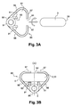
- the figure 3A is a diagrammatic representation, in cross-section, of the connecting means and the retaining means shown in FIG. figure 2 , with a highlighting of the movements that should be printed to allow assembly with the arm.
- the figure 3B is a diagrammatic representation, in cross section, of the connecting means and the connecting means shown in FIG. figure 2 , in an assembled position on the arm.
- Said ramp 10 comprises at least one watering orifice (not shown) under pressure which allows to distribute, preferably by spraying, said fluid on the glass surface.
- said watering orifices open on at least one of the longitudinal and lateral edges of the wiper blade 2.
- said ramp 10 is connected at one of its ends, directly or indirectly, to an inlet conduit 6 having in this case a substantially tubular shape so as to form a cannula.
- This inlet duct 6 extends on the opposite side to that where the wiper blade 2 is disposed, in the space between the drive arm 3 of the wiper blade 2, when the arm drive 3 and the brush 2 are assembled.
- the inlet duct 6 is preferably made of a material giving it flexibility properties, such as a material plastic, to facilitate the handling of the user when the latter proceeds for example to change the wiper blade 2.
- the ramp 10 for routing and distribution is generally indirectly connected to said inlet duct 6 via a connector 7 which comprises at least one outlet fitting and one inlet fitting (not shown) suitable for allow respectively the connection to the ramp 10 and to the inlet duct 6.
- said end portion 31 has an upper face whose length Y is smaller than the distance X separating on the one hand, a wall of the adapter 4 which is substantially perpendicular to said upper face and against which wall of the adapter said end portion 31 is in contact when the latter is assembled to the wiper blade 2, and secondly a free end of the inlet duct 6 to which is connected the connecting means 8.
- the point of connection between the conveying duct 5 and the inlet duct 6 of the fluid remote from the connecting device 4, 7 is shifted, and the assembling and disassembling operations are thus easy.
- the wiper system 1 also comprises a connecting means 8 adapted to directly or indirectly connect said transport conduit 5 to said ramp 10.
- said connecting means 8 has a substantially tubular shape, and comprises two ends 82 shaped so as to cooperate respectively with the ends of the inlet duct 6 and the inlet duct 5 which constitutes in this example the transport duct 5
- the ends 82 of the connection means 8 as well as the free ends of the inlet duct 6 and the inlet duct 5 are thus able to allow a removable attachment between these parts 5, 6, 8.
- the ends of the connecting means 8 may comprise a thread 83 adapted to cooperate with tapped orifices 60 appearing at the ends of the inlet and inlet ducts 6.
- each of the ends 82 of this connection means 8 may have substantially the shape of a right cone frustum, oriented such that the small bases are directly opposite the ends of the ducts 5 and 6 input when connecting.
- the ends 82 of the connection means 8 have dimensions allowing them to be partially sunk into said ends of the inlet and inlet ducts 6.
- connection means 8 is rigid and comprises a non-return valve (not shown) to prevent the reflux of the cleaning fluid and / or deicing to said source of the fluid.
- a retaining means 9 is able to ensure a removable attachment of the connecting means 8 on a portion of the rod 30, at a distance from said end portion 31.
- the retaining means 9 comprises a connecting means 90 adapted to cooperate with said rod portion 30 to ensure a fixation, said first fixation, removable said retaining means 9 on said arm 3, and a fastening means 91 adapted to ensure a fixation, said second fixing, removably connecting means 8 on the retaining means 9.
- the fastening means 91 is arranged to allow the portion of said connecting means 8 cooperating with the fastening means 91 to extend, in use position, substantially opposite the rod 30 to which is connected the connecting means 90.
- first housing 92 and the second housing 93 are arranged relative to each other so that in the connected position of the retaining means 9 on the portion of the rod 30, said portion of the rod 30 contributes maintaining the connecting means 8 in the second housing 93, preventing the expulsion of the connecting means 8 of the second housing 93 in at least one direction.
- the retaining means 9 is preferably made of a material or a set of materials allowing it to deform non-permanently.
- the retaining means 9 can be made from a polymer material having a yield strength that satisfies this constraint, the choice of this polymeric material falling within general competencies. of the skilled person.
- the elastic deformation capacity of the retaining means 9 advantageously allow it to be connected and disconnected to drive arms 3 having various dimensions.
- the parts of the connecting means 90 in contact with the drive arm 3 can thus deform and modify the dimensions including the first housing 92 and said slot 94, which facilitates the introduction of the drive arm 3 in these spaces.
- these elastic deformation properties may allow the connecting means 90 to grip a substantial portion of the portion of the rod 30 of the drive arm 3 to which the retaining means 9 is in contact after connection, which optimizes advantageously maintaining the retaining means 9.
- said fixing means 91 is able to ensure the second detachable snap-fastening of the connecting means 8 on the retaining means 9.
- the fixing means 91 has a shape conformity with the connection means 8 to allow this snap connection.
- the fastening means 91 comprises two longitudinally-oriented projections extending from said base 95 into the interior space of the retaining means 9, the spacing between the two projections 91 making it possible to arrange the connecting means 8 therein.
- two projections 91 preferably extend on either side of said axis of symmetry ( ⁇ ).
- the projections 91 are made of a material or a set of materials allowing them to deform non-permanently, which facilitates the snap connection between the connecting means 8 and the projections 91.
- the projections 91 preferably have a height allowing the drive arm 3 to bear on one of their sides after it has been introduced into the first housing 92, this which advantageously allows the connection means 8 to be maintained in said spacing and to block it in all directions.
- connection means 8 may comprise a collar 80 which has two opposite faces of which extends respectively a pipe 81 terminated by an end 82 having a thread 83.
- the spacing between two projections 91 is substantially equal to the diameter. connecting means 8 at said collar 80 to allow the snap connection.
- the retaining means 9 is able to be movable in translation relative to the portion of the rod 30 when connected to the latter, this translational movement being made possible thanks to the dimensions of the first housing 92 and / or the elastic properties of the retaining means 9.
- Disconnection of the transport conduit 5 of the drive arm 3 is performed by performing these steps in the opposite direction.
Landscapes
- Engineering & Computer Science (AREA)
- Mechanical Engineering (AREA)
- Water Supply & Treatment (AREA)
- Cleaning In General (AREA)
- Mutual Connection Of Rods And Tubes (AREA)
- Cleaning Implements For Floors, Carpets, Furniture, Walls, And The Like (AREA)
- Cleaning By Liquid Or Steam (AREA)
Applications Claiming Priority (1)
| Application Number | Priority Date | Filing Date | Title |
|---|---|---|---|
| FR1355555A FR3006973B1 (fr) | 2013-06-14 | 2013-06-14 | Systeme d'essuyage permettant la projection d'un fluide de nettoyage et/ou de degivrage au niveau d'un balai d'essuie-glace |
Publications (2)
| Publication Number | Publication Date |
|---|---|
| EP2813402A1 true EP2813402A1 (de) | 2014-12-17 |
| EP2813402B1 EP2813402B1 (de) | 2019-04-24 |
Family
ID=49212851
Family Applications (1)
| Application Number | Title | Priority Date | Filing Date |
|---|---|---|---|
| EP14171315.6A Active EP2813402B1 (de) | 2013-06-14 | 2014-06-05 | Reinigungssystem, das das Spritzen von Reinigungs- und/oder Enteisungsflüssigkeit auf der Höhe des Scheibenwischerblatts ermöglicht |
Country Status (4)
| Country | Link |
|---|---|
| US (1) | US9707936B2 (de) |
| EP (1) | EP2813402B1 (de) |
| CN (1) | CN104276144B (de) |
| FR (1) | FR3006973B1 (de) |
Cited By (5)
| Publication number | Priority date | Publication date | Assignee | Title |
|---|---|---|---|---|
| US10272878B2 (en) | 2014-07-17 | 2019-04-30 | Robert Bosch Gmbh | Wiper arm arrangement |
| WO2019120673A1 (de) * | 2017-12-21 | 2019-06-27 | Robert Bosch Gmbh | Wischarmvorrichtung |
| WO2020135970A1 (fr) * | 2018-12-26 | 2020-07-02 | Valeo Systèmes d'Essuyage | Kit de remplacement d'un balai d'essuyage |
| FR3112735A1 (fr) * | 2020-07-27 | 2022-01-28 | Valeo Systemes D'essuyage | Attache pour fixation d’une conduite fluidique sur un bras |
| WO2024003089A1 (fr) * | 2022-06-30 | 2024-01-04 | Valeo Systèmes D’Essuyage | Bras d'essuie-glace de véhicule automobile |
Families Citing this family (6)
| Publication number | Priority date | Publication date | Assignee | Title |
|---|---|---|---|---|
| FR3023813B1 (fr) * | 2014-07-17 | 2016-08-12 | Valeo Systemes Dessuyage | Systeme d'essuyage pour vehicule automobile avec systeme de lave-vitre |
| FR3065380B1 (fr) * | 2017-04-25 | 2019-06-21 | Valeo Systemes D'essuyage | Dispositif de nettoyage telescopique |
| EP3415381B1 (de) * | 2017-06-13 | 2021-02-17 | Valeo Systèmes d'Essuyage | Scheibenwischerarm mit mitteln zum festhalten eines flüssigkeitsabgabeschlauchs |
| DE102019212241A1 (de) * | 2019-08-15 | 2021-02-18 | Robert Bosch Gmbh | Wischarmadaptervorrichtung, Wischarm mit einer Wischarmadaptervorrichtung und Scheibenwischer mit einem Wischarm mit einer Wischarmadaptervorrichtung |
| DE102020214173A1 (de) | 2020-11-11 | 2022-05-12 | Robert Bosch Gesellschaft mit beschränkter Haftung | Wischarmvorrichtung |
| JP7658569B2 (ja) * | 2021-07-12 | 2025-04-08 | 株式会社東海理機 | ワイパアームのクランプ取付構造 |
Citations (4)
| Publication number | Priority date | Publication date | Assignee | Title |
|---|---|---|---|---|
| EP1918167A1 (de) * | 2006-10-30 | 2008-05-07 | Valeo Systèmes d'Essuyage | Vorrichtung zur Verbindung mit einem Wischblatt |
| DE102007062304A1 (de) * | 2007-12-21 | 2009-06-25 | Valeo Systèmes d'Essuyage | Wischblatt |
| WO2010006775A1 (fr) | 2008-07-15 | 2010-01-21 | Valeo Systemes D'essuyage | Systeme d'essuie-glace notamment pour vehicule automobile |
| DE102009017990A1 (de) * | 2009-04-21 | 2010-10-28 | Valeo Systèmes d'Essuyage | Flachwischblatt |
Family Cites Families (7)
| Publication number | Priority date | Publication date | Assignee | Title |
|---|---|---|---|---|
| US3757379A (en) * | 1972-03-13 | 1973-09-11 | R Benson | Windshield cleaning apparatus |
| US3969783A (en) * | 1975-06-04 | 1976-07-20 | Shipman William A | Combination windshield washer/wiper |
| FR2750100B1 (fr) * | 1996-06-25 | 1998-08-14 | Valeo Systemes Dessuyage | Dispositif de projection de liquide de lavage pour un essuie-glace de vehicule automobile et procede de realisation d'un tel dispositif |
| EP1876073B1 (de) * | 2006-07-04 | 2009-08-26 | Federal-Mogul S.A. | Scheibenwischervorrichtung |
| DE102008021457A1 (de) * | 2008-04-29 | 2009-11-05 | Valeo Systèmes d'Essuyage | Wischblatt sowie Wischarm |
| DE102011054066B4 (de) * | 2011-09-29 | 2023-07-06 | Valeo Systèmes d'Essuyage | Wischblatt zum Reinigen von Fahrzeugscheiben |
| FR2982222B1 (fr) * | 2011-11-09 | 2013-12-20 | Valeo Systemes Dessuyage | Essuie-glace et dispositif de maintien d'une canalisation d'alimentation en produit lave-glace a un bras d'actionnement de balai d'essuie-glace |
-
2013
- 2013-06-14 FR FR1355555A patent/FR3006973B1/fr not_active Expired - Fee Related
-
2014
- 2014-06-05 EP EP14171315.6A patent/EP2813402B1/de active Active
- 2014-06-11 US US14/302,191 patent/US9707936B2/en active Active
- 2014-06-13 CN CN201410445526.0A patent/CN104276144B/zh active Active
Patent Citations (4)
| Publication number | Priority date | Publication date | Assignee | Title |
|---|---|---|---|---|
| EP1918167A1 (de) * | 2006-10-30 | 2008-05-07 | Valeo Systèmes d'Essuyage | Vorrichtung zur Verbindung mit einem Wischblatt |
| DE102007062304A1 (de) * | 2007-12-21 | 2009-06-25 | Valeo Systèmes d'Essuyage | Wischblatt |
| WO2010006775A1 (fr) | 2008-07-15 | 2010-01-21 | Valeo Systemes D'essuyage | Systeme d'essuie-glace notamment pour vehicule automobile |
| DE102009017990A1 (de) * | 2009-04-21 | 2010-10-28 | Valeo Systèmes d'Essuyage | Flachwischblatt |
Cited By (11)
| Publication number | Priority date | Publication date | Assignee | Title |
|---|---|---|---|---|
| US10272878B2 (en) | 2014-07-17 | 2019-04-30 | Robert Bosch Gmbh | Wiper arm arrangement |
| WO2019120673A1 (de) * | 2017-12-21 | 2019-06-27 | Robert Bosch Gmbh | Wischarmvorrichtung |
| US11305735B2 (en) | 2017-12-21 | 2022-04-19 | Robert Bosch Gmbh | Wiper arm device |
| WO2020135970A1 (fr) * | 2018-12-26 | 2020-07-02 | Valeo Systèmes d'Essuyage | Kit de remplacement d'un balai d'essuyage |
| FR3091240A1 (fr) * | 2018-12-26 | 2020-07-03 | Valeo Systemes D'essuyage | Kit de remplacement d’un balai d’essuyage |
| US11958443B2 (en) | 2018-12-26 | 2024-04-16 | Valeo Systèmes d'Essuyage | Wiper blade replacement kit |
| FR3112735A1 (fr) * | 2020-07-27 | 2022-01-28 | Valeo Systemes D'essuyage | Attache pour fixation d’une conduite fluidique sur un bras |
| WO2022023031A1 (fr) * | 2020-07-27 | 2022-02-03 | Valeo Systèmes d'Essuyage | Attache pour fixation d'une conduite fluidique sur un bras |
| US12122329B2 (en) | 2020-07-27 | 2024-10-22 | Valeo Systemes D'essuyage | Clip for attaching a fluid line to an arm |
| WO2024003089A1 (fr) * | 2022-06-30 | 2024-01-04 | Valeo Systèmes D’Essuyage | Bras d'essuie-glace de véhicule automobile |
| FR3137346A1 (fr) * | 2022-06-30 | 2024-01-05 | Valeo Systèmes D’Essuyage | bras d’essuie-glace de véhicule automobile |
Also Published As
| Publication number | Publication date |
|---|---|
| CN104276144B (zh) | 2019-05-14 |
| US9707936B2 (en) | 2017-07-18 |
| US20140366301A1 (en) | 2014-12-18 |
| EP2813402B1 (de) | 2019-04-24 |
| CN104276144A (zh) | 2015-01-14 |
| FR3006973B1 (fr) | 2015-07-03 |
| FR3006973A1 (fr) | 2014-12-19 |
Similar Documents
| Publication | Publication Date | Title |
|---|---|---|
| EP2813402B1 (de) | Reinigungssystem, das das Spritzen von Reinigungs- und/oder Enteisungsflüssigkeit auf der Höhe des Scheibenwischerblatts ermöglicht | |
| EP2707257B1 (de) | Verbindungshalterung, mechanischer verbinder und wischvorrichtung für ein kraftfahrzeug | |
| EP2671766B1 (de) | Hydraulischer Steckverbinder, insbesondere für Scheibenwischsystem eines Kraftfahrzeugs | |
| EP2528786B1 (de) | In einen verbinder eines wischerarms für eine fahrzeugseitige waschleitung eingebaute schraube | |
| EP2691272B1 (de) | Endstück mit einer vorrichtung zur sicherung eines wischblatts | |
| FR3007719A1 (fr) | Dispositif de bras d'essuie-glace | |
| WO2012072299A1 (fr) | Ensemble comprenant une piece terminale d'un bras d'essuie-glace et un connecteur electrique | |
| FR3056510A1 (fr) | Adaptateur pour la connexion d'un balai d'essuyage a un bras d'entrainement d'un systeme d'essuyage pour vehicule automobile | |
| EP2691274B1 (de) | Erstes und zweites teil eines endstückes für einen scheibenwischer | |
| FR2994144A1 (fr) | Dispositif de connexion entre un bras d'essuyage et un balai d'essuyage, comprenant un tube surmoule | |
| EP2709880A1 (de) | Flüssigsprühvorrichtung für ein wischblatt | |
| EP3040247A1 (de) | Scheibenwischerarm mit sprühdüse | |
| EP2886404A1 (de) | Anschlüsse für ein Scheibenwischer eines Fahrzeugs | |
| FR3096325A1 (fr) | Dispositif de balai d’essuie-glace | |
| FR3039810A1 (fr) | Adaptateur de balai d'essuie-glace | |
| EP2734423B1 (de) | Stütze für befestigungsvorrichtung und waschflüssigkeitszuführvorrichtung für eine fahrzeug wischeranlage | |
| FR2928887A1 (fr) | Agencement de balai d'essuie-glace pour vehicules automobiles | |
| EP2965958B1 (de) | Einheit aus einem mechanischen anschluss und einer kanüle für ein scheibenwischerblatt eines fahrzeugs | |
| FR3040155A1 (fr) | Dispositif de balai d'essuie-glace | |
| FR2971985A1 (fr) | Balai d'essuie-glace pour le nettoyage de vitres de vehicules | |
| EP3012163B1 (de) | Vorrichtung zum spritzen von scheibenwaschflüssigkeit für einen scheibenwischerarm des scheibenwischersystems eines fahrzeugs | |
| EP3312062A1 (de) | Anschlussmodul für eine wischvorrichtung eines kraftfahrzeugs | |
| FR3031949A1 (fr) | Organe longitudinal pour un balai d'essuie-glace | |
| FR3102962A1 (fr) | Dispositif de balai d'essuie-glace | |
| FR3015397A1 (fr) | Moyen de support pour un systeme d'essuyage d'une vitre d'un vehicule |
Legal Events
| Date | Code | Title | Description |
|---|---|---|---|
| 17P | Request for examination filed |
Effective date: 20140605 |
|
| AK | Designated contracting states |
Kind code of ref document: A1 Designated state(s): AL AT BE BG CH CY CZ DE DK EE ES FI FR GB GR HR HU IE IS IT LI LT LU LV MC MK MT NL NO PL PT RO RS SE SI SK SM TR |
|
| AX | Request for extension of the european patent |
Extension state: BA ME |
|
| PUAI | Public reference made under article 153(3) epc to a published international application that has entered the european phase |
Free format text: ORIGINAL CODE: 0009012 |
|
| GRAP | Despatch of communication of intention to grant a patent |
Free format text: ORIGINAL CODE: EPIDOSNIGR1 |
|
| STAA | Information on the status of an ep patent application or granted ep patent |
Free format text: STATUS: GRANT OF PATENT IS INTENDED |
|
| RIC1 | Information provided on ipc code assigned before grant |
Ipc: B60S 1/38 20060101AFI20181012BHEP |
|
| INTG | Intention to grant announced |
Effective date: 20181108 |
|
| GRAS | Grant fee paid |
Free format text: ORIGINAL CODE: EPIDOSNIGR3 |
|
| GRAA | (expected) grant |
Free format text: ORIGINAL CODE: 0009210 |
|
| STAA | Information on the status of an ep patent application or granted ep patent |
Free format text: STATUS: THE PATENT HAS BEEN GRANTED |
|
| AK | Designated contracting states |
Kind code of ref document: B1 Designated state(s): AL AT BE BG CH CY CZ DE DK EE ES FI FR GB GR HR HU IE IS IT LI LT LU LV MC MK MT NL NO PL PT RO RS SE SI SK SM TR |
|
| REG | Reference to a national code |
Ref country code: GB Ref legal event code: FG4D Free format text: NOT ENGLISH |
|
| REG | Reference to a national code |
Ref country code: CH Ref legal event code: EP |
|
| REG | Reference to a national code |
Ref country code: AT Ref legal event code: REF Ref document number: 1123761 Country of ref document: AT Kind code of ref document: T Effective date: 20190515 Ref country code: IE Ref legal event code: FG4D Free format text: LANGUAGE OF EP DOCUMENT: FRENCH |
|
| REG | Reference to a national code |
Ref country code: DE Ref legal event code: R096 Ref document number: 602014045203 Country of ref document: DE |
|
| REG | Reference to a national code |
Ref country code: NL Ref legal event code: MP Effective date: 20190424 |
|
| REG | Reference to a national code |
Ref country code: LT Ref legal event code: MG4D |
|
| PG25 | Lapsed in a contracting state [announced via postgrant information from national office to epo] |
Ref country code: NL Free format text: LAPSE BECAUSE OF FAILURE TO SUBMIT A TRANSLATION OF THE DESCRIPTION OR TO PAY THE FEE WITHIN THE PRESCRIBED TIME-LIMIT Effective date: 20190424 |
|
| PG25 | Lapsed in a contracting state [announced via postgrant information from national office to epo] |
Ref country code: FI Free format text: LAPSE BECAUSE OF FAILURE TO SUBMIT A TRANSLATION OF THE DESCRIPTION OR TO PAY THE FEE WITHIN THE PRESCRIBED TIME-LIMIT Effective date: 20190424 Ref country code: NO Free format text: LAPSE BECAUSE OF FAILURE TO SUBMIT A TRANSLATION OF THE DESCRIPTION OR TO PAY THE FEE WITHIN THE PRESCRIBED TIME-LIMIT Effective date: 20190724 Ref country code: ES Free format text: LAPSE BECAUSE OF FAILURE TO SUBMIT A TRANSLATION OF THE DESCRIPTION OR TO PAY THE FEE WITHIN THE PRESCRIBED TIME-LIMIT Effective date: 20190424 Ref country code: PT Free format text: LAPSE BECAUSE OF FAILURE TO SUBMIT A TRANSLATION OF THE DESCRIPTION OR TO PAY THE FEE WITHIN THE PRESCRIBED TIME-LIMIT Effective date: 20190824 Ref country code: SE Free format text: LAPSE BECAUSE OF FAILURE TO SUBMIT A TRANSLATION OF THE DESCRIPTION OR TO PAY THE FEE WITHIN THE PRESCRIBED TIME-LIMIT Effective date: 20190424 Ref country code: AL Free format text: LAPSE BECAUSE OF FAILURE TO SUBMIT A TRANSLATION OF THE DESCRIPTION OR TO PAY THE FEE WITHIN THE PRESCRIBED TIME-LIMIT Effective date: 20190424 Ref country code: LT Free format text: LAPSE BECAUSE OF FAILURE TO SUBMIT A TRANSLATION OF THE DESCRIPTION OR TO PAY THE FEE WITHIN THE PRESCRIBED TIME-LIMIT Effective date: 20190424 Ref country code: HR Free format text: LAPSE BECAUSE OF FAILURE TO SUBMIT A TRANSLATION OF THE DESCRIPTION OR TO PAY THE FEE WITHIN THE PRESCRIBED TIME-LIMIT Effective date: 20190424 |
|
| PG25 | Lapsed in a contracting state [announced via postgrant information from national office to epo] |
Ref country code: PL Free format text: LAPSE BECAUSE OF FAILURE TO SUBMIT A TRANSLATION OF THE DESCRIPTION OR TO PAY THE FEE WITHIN THE PRESCRIBED TIME-LIMIT Effective date: 20190424 Ref country code: RS Free format text: LAPSE BECAUSE OF FAILURE TO SUBMIT A TRANSLATION OF THE DESCRIPTION OR TO PAY THE FEE WITHIN THE PRESCRIBED TIME-LIMIT Effective date: 20190424 Ref country code: GR Free format text: LAPSE BECAUSE OF FAILURE TO SUBMIT A TRANSLATION OF THE DESCRIPTION OR TO PAY THE FEE WITHIN THE PRESCRIBED TIME-LIMIT Effective date: 20190725 Ref country code: BG Free format text: LAPSE BECAUSE OF FAILURE TO SUBMIT A TRANSLATION OF THE DESCRIPTION OR TO PAY THE FEE WITHIN THE PRESCRIBED TIME-LIMIT Effective date: 20190724 Ref country code: LV Free format text: LAPSE BECAUSE OF FAILURE TO SUBMIT A TRANSLATION OF THE DESCRIPTION OR TO PAY THE FEE WITHIN THE PRESCRIBED TIME-LIMIT Effective date: 20190424 |
|
| REG | Reference to a national code |
Ref country code: AT Ref legal event code: MK05 Ref document number: 1123761 Country of ref document: AT Kind code of ref document: T Effective date: 20190424 |
|
| PG25 | Lapsed in a contracting state [announced via postgrant information from national office to epo] |
Ref country code: IS Free format text: LAPSE BECAUSE OF FAILURE TO SUBMIT A TRANSLATION OF THE DESCRIPTION OR TO PAY THE FEE WITHIN THE PRESCRIBED TIME-LIMIT Effective date: 20190824 |
|
| REG | Reference to a national code |
Ref country code: DE Ref legal event code: R097 Ref document number: 602014045203 Country of ref document: DE |
|
| PG25 | Lapsed in a contracting state [announced via postgrant information from national office to epo] |
Ref country code: SK Free format text: LAPSE BECAUSE OF FAILURE TO SUBMIT A TRANSLATION OF THE DESCRIPTION OR TO PAY THE FEE WITHIN THE PRESCRIBED TIME-LIMIT Effective date: 20190424 Ref country code: EE Free format text: LAPSE BECAUSE OF FAILURE TO SUBMIT A TRANSLATION OF THE DESCRIPTION OR TO PAY THE FEE WITHIN THE PRESCRIBED TIME-LIMIT Effective date: 20190424 Ref country code: CZ Free format text: LAPSE BECAUSE OF FAILURE TO SUBMIT A TRANSLATION OF THE DESCRIPTION OR TO PAY THE FEE WITHIN THE PRESCRIBED TIME-LIMIT Effective date: 20190424 Ref country code: RO Free format text: LAPSE BECAUSE OF FAILURE TO SUBMIT A TRANSLATION OF THE DESCRIPTION OR TO PAY THE FEE WITHIN THE PRESCRIBED TIME-LIMIT Effective date: 20190424 Ref country code: DK Free format text: LAPSE BECAUSE OF FAILURE TO SUBMIT A TRANSLATION OF THE DESCRIPTION OR TO PAY THE FEE WITHIN THE PRESCRIBED TIME-LIMIT Effective date: 20190424 Ref country code: AT Free format text: LAPSE BECAUSE OF FAILURE TO SUBMIT A TRANSLATION OF THE DESCRIPTION OR TO PAY THE FEE WITHIN THE PRESCRIBED TIME-LIMIT Effective date: 20190424 Ref country code: MC Free format text: LAPSE BECAUSE OF FAILURE TO SUBMIT A TRANSLATION OF THE DESCRIPTION OR TO PAY THE FEE WITHIN THE PRESCRIBED TIME-LIMIT Effective date: 20190424 |
|
| REG | Reference to a national code |
Ref country code: CH Ref legal event code: PL |
|
| PG25 | Lapsed in a contracting state [announced via postgrant information from national office to epo] |
Ref country code: IT Free format text: LAPSE BECAUSE OF FAILURE TO SUBMIT A TRANSLATION OF THE DESCRIPTION OR TO PAY THE FEE WITHIN THE PRESCRIBED TIME-LIMIT Effective date: 20190424 Ref country code: SM Free format text: LAPSE BECAUSE OF FAILURE TO SUBMIT A TRANSLATION OF THE DESCRIPTION OR TO PAY THE FEE WITHIN THE PRESCRIBED TIME-LIMIT Effective date: 20190424 |
|
| PLBE | No opposition filed within time limit |
Free format text: ORIGINAL CODE: 0009261 |
|
| STAA | Information on the status of an ep patent application or granted ep patent |
Free format text: STATUS: NO OPPOSITION FILED WITHIN TIME LIMIT |
|
| PG25 | Lapsed in a contracting state [announced via postgrant information from national office to epo] |
Ref country code: TR Free format text: LAPSE BECAUSE OF FAILURE TO SUBMIT A TRANSLATION OF THE DESCRIPTION OR TO PAY THE FEE WITHIN THE PRESCRIBED TIME-LIMIT Effective date: 20190424 |
|
| 26N | No opposition filed |
Effective date: 20200127 |
|
| PG25 | Lapsed in a contracting state [announced via postgrant information from national office to epo] |
Ref country code: IE Free format text: LAPSE BECAUSE OF NON-PAYMENT OF DUE FEES Effective date: 20190605 |
|
| PG25 | Lapsed in a contracting state [announced via postgrant information from national office to epo] |
Ref country code: LI Free format text: LAPSE BECAUSE OF NON-PAYMENT OF DUE FEES Effective date: 20190630 Ref country code: SI Free format text: LAPSE BECAUSE OF FAILURE TO SUBMIT A TRANSLATION OF THE DESCRIPTION OR TO PAY THE FEE WITHIN THE PRESCRIBED TIME-LIMIT Effective date: 20190424 Ref country code: LU Free format text: LAPSE BECAUSE OF NON-PAYMENT OF DUE FEES Effective date: 20190605 Ref country code: CH Free format text: LAPSE BECAUSE OF NON-PAYMENT OF DUE FEES Effective date: 20190630 |
|
| PGFP | Annual fee paid to national office [announced via postgrant information from national office to epo] |
Ref country code: BE Payment date: 20200616 Year of fee payment: 7 Ref country code: GB Payment date: 20200619 Year of fee payment: 7 |
|
| PG25 | Lapsed in a contracting state [announced via postgrant information from national office to epo] |
Ref country code: CY Free format text: LAPSE BECAUSE OF FAILURE TO SUBMIT A TRANSLATION OF THE DESCRIPTION OR TO PAY THE FEE WITHIN THE PRESCRIBED TIME-LIMIT Effective date: 20190424 |
|
| PG25 | Lapsed in a contracting state [announced via postgrant information from national office to epo] |
Ref country code: HU Free format text: LAPSE BECAUSE OF FAILURE TO SUBMIT A TRANSLATION OF THE DESCRIPTION OR TO PAY THE FEE WITHIN THE PRESCRIBED TIME-LIMIT; INVALID AB INITIO Effective date: 20140605 Ref country code: MT Free format text: LAPSE BECAUSE OF FAILURE TO SUBMIT A TRANSLATION OF THE DESCRIPTION OR TO PAY THE FEE WITHIN THE PRESCRIBED TIME-LIMIT Effective date: 20190424 |
|
| GBPC | Gb: european patent ceased through non-payment of renewal fee |
Effective date: 20210605 |
|
| REG | Reference to a national code |
Ref country code: BE Ref legal event code: MM Effective date: 20210630 |
|
| PG25 | Lapsed in a contracting state [announced via postgrant information from national office to epo] |
Ref country code: GB Free format text: LAPSE BECAUSE OF NON-PAYMENT OF DUE FEES Effective date: 20210605 |
|
| PG25 | Lapsed in a contracting state [announced via postgrant information from national office to epo] |
Ref country code: MK Free format text: LAPSE BECAUSE OF FAILURE TO SUBMIT A TRANSLATION OF THE DESCRIPTION OR TO PAY THE FEE WITHIN THE PRESCRIBED TIME-LIMIT Effective date: 20190424 |
|
| PG25 | Lapsed in a contracting state [announced via postgrant information from national office to epo] |
Ref country code: BE Free format text: LAPSE BECAUSE OF NON-PAYMENT OF DUE FEES Effective date: 20210630 |
|
| P01 | Opt-out of the competence of the unified patent court (upc) registered |
Effective date: 20230528 |
|
| PGFP | Annual fee paid to national office [announced via postgrant information from national office to epo] |
Ref country code: DE Payment date: 20250617 Year of fee payment: 12 |
|
| PGFP | Annual fee paid to national office [announced via postgrant information from national office to epo] |
Ref country code: FR Payment date: 20250630 Year of fee payment: 12 |