EP2813402A1 - Wiping system enabling the spraying of a fluid for cleaning and/or de-icing at a windscreen-wiper blade - Google Patents
Wiping system enabling the spraying of a fluid for cleaning and/or de-icing at a windscreen-wiper blade Download PDFInfo
- Publication number
- EP2813402A1 EP2813402A1 EP14171315.6A EP14171315A EP2813402A1 EP 2813402 A1 EP2813402 A1 EP 2813402A1 EP 14171315 A EP14171315 A EP 14171315A EP 2813402 A1 EP2813402 A1 EP 2813402A1
- Authority
- EP
- European Patent Office
- Prior art keywords
- wiper system
- rod
- connecting means
- retaining means
- fluid
- Prior art date
- Legal status (The legal status is an assumption and is not a legal conclusion. Google has not performed a legal analysis and makes no representation as to the accuracy of the status listed.)
- Granted
Links
Images

Classifications
-
- B—PERFORMING OPERATIONS; TRANSPORTING
- B60—VEHICLES IN GENERAL
- B60S—SERVICING, CLEANING, REPAIRING, SUPPORTING, LIFTING, OR MANOEUVRING OF VEHICLES, NOT OTHERWISE PROVIDED FOR
- B60S1/00—Cleaning of vehicles
- B60S1/02—Cleaning windscreens, windows or optical devices
- B60S1/46—Cleaning windscreens, windows or optical devices using liquid; Windscreen washers
- B60S1/48—Liquid supply therefor
- B60S1/52—Arrangement of nozzles; Liquid spreading means
- B60S1/522—Arrangement of nozzles; Liquid spreading means moving liquid spreading means, e.g. arranged in wiper arms
-
- B—PERFORMING OPERATIONS; TRANSPORTING
- B60—VEHICLES IN GENERAL
- B60S—SERVICING, CLEANING, REPAIRING, SUPPORTING, LIFTING, OR MANOEUVRING OF VEHICLES, NOT OTHERWISE PROVIDED FOR
- B60S1/00—Cleaning of vehicles
- B60S1/02—Cleaning windscreens, windows or optical devices
- B60S1/04—Wipers or the like, e.g. scrapers
- B60S1/32—Wipers or the like, e.g. scrapers characterised by constructional features of wiper blade arms or blades
- B60S1/34—Wiper arms; Mountings therefor
- B60S1/3415—Wiper arms; Mountings therefor with means for supplying cleaning fluid to windscreen cleaners, e.g. washers
-
- B—PERFORMING OPERATIONS; TRANSPORTING
- B60—VEHICLES IN GENERAL
- B60S—SERVICING, CLEANING, REPAIRING, SUPPORTING, LIFTING, OR MANOEUVRING OF VEHICLES, NOT OTHERWISE PROVIDED FOR
- B60S1/00—Cleaning of vehicles
- B60S1/02—Cleaning windscreens, windows or optical devices
- B60S1/04—Wipers or the like, e.g. scrapers
- B60S1/32—Wipers or the like, e.g. scrapers characterised by constructional features of wiper blade arms or blades
- B60S1/38—Wiper blades
- B60S1/3848—Flat-type wiper blade, i.e. without harness
- B60S1/3849—Connectors therefor; Connection to wiper arm; Attached to blade
- B60S1/3862—Transport of liquid there through
-
- B—PERFORMING OPERATIONS; TRANSPORTING
- B60—VEHICLES IN GENERAL
- B60S—SERVICING, CLEANING, REPAIRING, SUPPORTING, LIFTING, OR MANOEUVRING OF VEHICLES, NOT OTHERWISE PROVIDED FOR
- B60S1/00—Cleaning of vehicles
- B60S1/02—Cleaning windscreens, windows or optical devices
- B60S1/46—Cleaning windscreens, windows or optical devices using liquid; Windscreen washers
- B60S1/48—Liquid supply therefor
- B60S1/52—Arrangement of nozzles; Liquid spreading means
- B60S1/522—Arrangement of nozzles; Liquid spreading means moving liquid spreading means, e.g. arranged in wiper arms
- B60S1/524—Arrangement of nozzles; Liquid spreading means moving liquid spreading means, e.g. arranged in wiper arms arranged in wiper blades
Definitions
- the present invention relates to a wiper system for the projection of a cleaning fluid and / or deicing at at least one wiper blade.
- the wiper systems allowing the direct discharge of the cleaning and / or deicing fluid at a wiper blade generally comprise at least one wiper blade which comprises at least one ramp conveying said fluid; at least one drive arm shaped so as to drive the wiper blade to a glass surface such as a window or a windshield, which is connected by means of a feed device to a source cleaning fluid and / or deicing fluid; connecting means for connecting the supply device to the cleaning fluid and / or defrosting transport ramp.
- a wiper system of this type is for example described in the international patent application published under the number WO 2010/006775 .
- This wiper system comprises a wiper blade articulated on an actuating arm via an adapter connected on the one hand to said arm and on the other hand to a hydraulic connector which is itself connected broom audit.
- This wiper system also comprises a cleaning fluid and / or deicing fluid inlet pipe connected to an input connector of the hydraulic connector by means of a rigid junction element.
- the arm may comprise locking means which comprise a cutout formed either in one of the walls of the adapter or of the arm or in a part attached to said adapter, these locking means having a shape allowing the rigid junction element to be able to forcefully catch in this cutout temporarily.
- connection between the fluid inlet pipe and the brush is made at the adapter or at the end portion of the arm which has substantially the shape of a yoke, this which does not allow completely free access to the connection, the arm to be rotated or disassembled relative to the blade when it is desired to connect or disconnect the inlet pipe to the arm.
- the rigid junction member is pressed or forcibly clamped in the cutout or in the insert by imparting a translational movement.
- the rigid connecting element is not blocked in all directions, the latter being ejected from its housing in the opposite direction to that of said translational movement.
- the present invention is intended in particular to overcome these major drawbacks by proposing a wiper system for the projection of a cleaning fluid and / or deicing at at least one wiper blade, which allows to easily connect the fluid inlet duct to the drive arm, without the need to move or disassemble the arm relative to the blade.
- Such a retaining means may for example be made in the form of one or more inserts (s) on the rod, in particular by crimping, gluing, overmolding or welding on the rod, such as by ultrasonic welding, but can also come from matter with the stem.
- the retaining means can be made alternately removable (removable) or not removable from the rod.
- the retaining means advantageously makes it possible to connect and disconnect said transport duct to the arm without the need for a specific cut in the drive arm, intended to cooperate with a specific form of a specific connecting piece.
- the wiper system according to the invention is such that said connection device comprises a connector attached to said wiper, said wiper system comprising an inlet conduit of said fluid in said connector, said inlet duct being capable of channeling said fluid from said connecting means to said connector.
- the wiper system according to the invention is such that said attachment of said connecting means on said rod is removable.
- said end portion has an upper face whose length is less than the distance separating on the one hand, a wall of the adapter which is substantially perpendicular to said upper face and against which wall of the adapter said portion of end is in contact when the latter is assembled to the wiper blade, and separating on the other hand a free end of the inlet duct on which is connected the connecting means.
- the point of connection between the transport duct and the fluid inlet duct is shifted away from the connection device, and the assembly and disassembly operations are thus easy.
- the wiper system according to the invention is such that said fixing means is adapted to ensure a removable attachment of said connecting means on said retaining means.
- said second attachment is removable.
- said fixing means is adapted to provide said second removable attachment by snapping said connecting means on said retaining means.
- said fixing means is adapted to allow locking of the connection means in all directions.
- the first housing and the second housing are arranged relative to each other so that in a connected position of the retaining means on the rod, a portion of the rod contributes to maintaining said connection means in the second dwelling.
- the wiper system makes it possible to secure the connection means in all directions.
- said connecting means comprises walls delimiting a slot at which the first housing opens, said slot being adapted to allow the introduction of a portion of the rod in said retaining means.
- the fastening means comprises two projections extending from said base into the interior space of the retaining means, the spacing between two projections making it possible to dispose in said space of said means of connection.
- the retaining means is made of a material or a set of materials allowing it to deform elastically.
- the elastic deformation capabilities of the retaining means advantageously allow the retaining means to be connected and disconnected to drive arms of various dimensions, the slot being able to expand for example at the moment of introduction of the arm of drive then retract when the rod of the drive arm is fully in said first housing.
- the elasticity of the connecting means makes it possible to grip a portion of the rod of the drive arm without causing shears.
- the retaining means is made by molding.
- the retaining means is adapted to be movable in translation relative to a portion of the rod when connected to the rod.
- the wiper system according to the invention is such that it comprises a locking means in position of the retaining means on the rod in at least one direction of longitudinal extension of said rod.
- the blocking means mentioned above is such as to block any movement of the retaining means relative to said rod.
- This locking means in position of the retaining means on the rod is for example made by a shape and a counterform respectively located on the retaining means and on the rod.
- the Figure 1A is a schematic representation of a wiper system according to the invention which comprises a wiper blade articulated on an actuating arm, with a highlighting of the retaining means making it possible in particular to connect the transport conduit of the fluid to said arm.
- FIG. Figure 1B is a schematic representation of the wiper system according to the invention shown in FIG. Figure 1A , on which the arm and the broom are in disassembled position.
- the figure 2 is a diagrammatic representation of the retaining means and the connecting means represented on the Figures 1A and 1B , in the assembled position and in the disassembled position.
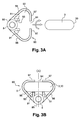
- the figure 3A is a diagrammatic representation, in cross-section, of the connecting means and the retaining means shown in FIG. figure 2 , with a highlighting of the movements that should be printed to allow assembly with the arm.
- the figure 3B is a diagrammatic representation, in cross section, of the connecting means and the connecting means shown in FIG. figure 2 , in an assembled position on the arm.
- Said ramp 10 comprises at least one watering orifice (not shown) under pressure which allows to distribute, preferably by spraying, said fluid on the glass surface.
- said watering orifices open on at least one of the longitudinal and lateral edges of the wiper blade 2.
- said ramp 10 is connected at one of its ends, directly or indirectly, to an inlet conduit 6 having in this case a substantially tubular shape so as to form a cannula.
- This inlet duct 6 extends on the opposite side to that where the wiper blade 2 is disposed, in the space between the drive arm 3 of the wiper blade 2, when the arm drive 3 and the brush 2 are assembled.
- the inlet duct 6 is preferably made of a material giving it flexibility properties, such as a material plastic, to facilitate the handling of the user when the latter proceeds for example to change the wiper blade 2.
- the ramp 10 for routing and distribution is generally indirectly connected to said inlet duct 6 via a connector 7 which comprises at least one outlet fitting and one inlet fitting (not shown) suitable for allow respectively the connection to the ramp 10 and to the inlet duct 6.
- said end portion 31 has an upper face whose length Y is smaller than the distance X separating on the one hand, a wall of the adapter 4 which is substantially perpendicular to said upper face and against which wall of the adapter said end portion 31 is in contact when the latter is assembled to the wiper blade 2, and secondly a free end of the inlet duct 6 to which is connected the connecting means 8.
- the point of connection between the conveying duct 5 and the inlet duct 6 of the fluid remote from the connecting device 4, 7 is shifted, and the assembling and disassembling operations are thus easy.
- the wiper system 1 also comprises a connecting means 8 adapted to directly or indirectly connect said transport conduit 5 to said ramp 10.
- said connecting means 8 has a substantially tubular shape, and comprises two ends 82 shaped so as to cooperate respectively with the ends of the inlet duct 6 and the inlet duct 5 which constitutes in this example the transport duct 5
- the ends 82 of the connection means 8 as well as the free ends of the inlet duct 6 and the inlet duct 5 are thus able to allow a removable attachment between these parts 5, 6, 8.
- the ends of the connecting means 8 may comprise a thread 83 adapted to cooperate with tapped orifices 60 appearing at the ends of the inlet and inlet ducts 6.
- each of the ends 82 of this connection means 8 may have substantially the shape of a right cone frustum, oriented such that the small bases are directly opposite the ends of the ducts 5 and 6 input when connecting.
- the ends 82 of the connection means 8 have dimensions allowing them to be partially sunk into said ends of the inlet and inlet ducts 6.
- connection means 8 is rigid and comprises a non-return valve (not shown) to prevent the reflux of the cleaning fluid and / or deicing to said source of the fluid.
- a retaining means 9 is able to ensure a removable attachment of the connecting means 8 on a portion of the rod 30, at a distance from said end portion 31.
- the retaining means 9 comprises a connecting means 90 adapted to cooperate with said rod portion 30 to ensure a fixation, said first fixation, removable said retaining means 9 on said arm 3, and a fastening means 91 adapted to ensure a fixation, said second fixing, removably connecting means 8 on the retaining means 9.
- the fastening means 91 is arranged to allow the portion of said connecting means 8 cooperating with the fastening means 91 to extend, in use position, substantially opposite the rod 30 to which is connected the connecting means 90.
- first housing 92 and the second housing 93 are arranged relative to each other so that in the connected position of the retaining means 9 on the portion of the rod 30, said portion of the rod 30 contributes maintaining the connecting means 8 in the second housing 93, preventing the expulsion of the connecting means 8 of the second housing 93 in at least one direction.
- the retaining means 9 is preferably made of a material or a set of materials allowing it to deform non-permanently.
- the retaining means 9 can be made from a polymer material having a yield strength that satisfies this constraint, the choice of this polymeric material falling within general competencies. of the skilled person.
- the elastic deformation capacity of the retaining means 9 advantageously allow it to be connected and disconnected to drive arms 3 having various dimensions.
- the parts of the connecting means 90 in contact with the drive arm 3 can thus deform and modify the dimensions including the first housing 92 and said slot 94, which facilitates the introduction of the drive arm 3 in these spaces.
- these elastic deformation properties may allow the connecting means 90 to grip a substantial portion of the portion of the rod 30 of the drive arm 3 to which the retaining means 9 is in contact after connection, which optimizes advantageously maintaining the retaining means 9.
- said fixing means 91 is able to ensure the second detachable snap-fastening of the connecting means 8 on the retaining means 9.
- the fixing means 91 has a shape conformity with the connection means 8 to allow this snap connection.
- the fastening means 91 comprises two longitudinally-oriented projections extending from said base 95 into the interior space of the retaining means 9, the spacing between the two projections 91 making it possible to arrange the connecting means 8 therein.
- two projections 91 preferably extend on either side of said axis of symmetry ( ⁇ ).
- the projections 91 are made of a material or a set of materials allowing them to deform non-permanently, which facilitates the snap connection between the connecting means 8 and the projections 91.
- the projections 91 preferably have a height allowing the drive arm 3 to bear on one of their sides after it has been introduced into the first housing 92, this which advantageously allows the connection means 8 to be maintained in said spacing and to block it in all directions.
- connection means 8 may comprise a collar 80 which has two opposite faces of which extends respectively a pipe 81 terminated by an end 82 having a thread 83.
- the spacing between two projections 91 is substantially equal to the diameter. connecting means 8 at said collar 80 to allow the snap connection.
- the retaining means 9 is able to be movable in translation relative to the portion of the rod 30 when connected to the latter, this translational movement being made possible thanks to the dimensions of the first housing 92 and / or the elastic properties of the retaining means 9.
- Disconnection of the transport conduit 5 of the drive arm 3 is performed by performing these steps in the opposite direction.
Landscapes
- Engineering & Computer Science (AREA)
- Mechanical Engineering (AREA)
- Water Supply & Treatment (AREA)
- Cleaning In General (AREA)
- Mutual Connection Of Rods And Tubes (AREA)
- Cleaning Implements For Floors, Carpets, Furniture, Walls, And The Like (AREA)
- Cleaning By Liquid Or Steam (AREA)
Abstract
L'invention concerne un système d'essuyage (1) comprenant : - un bras d'entraînement (3) comprenant une tige (30) prolongée par une portion d'extrémité (31) apte à être connectée à un balai d'essuie-glace (2) ; - un balai d'essuie-glace (2) assemblé à ladite portion d'extrémité (31) et comprenant au moins une rampe (10) apte à canaliser un fluide de nettoyage et/ou de dégivrage ; caractérisé en ce que ledit système d'essuyage (1) comprend : - un conduit de transport (5) dudit fluide qui chemine au moins en partie le long de ladite tige (30), ledit conduit (5) contribuant à canaliser ledit fluide vers ladite rampe (10) ; - un moyen de raccordement (8) contribuant à assurer une connexion amovible entre ledit conduit (5) et ladite rampe (10) et contribuant à canaliser ledit fluide depuis ledit conduit (5) vers ladite rampe (10) ; - un moyen de retenue (9) apte à assurer une fixation dudit moyen de raccordement (8) sur ladite tige (30).The invention relates to a wiper system (1) comprising: - A drive arm (3) comprising a rod (30) extended by an end portion (31) adapted to be connected to a wiper blade (2); - A wiper blade (2) assembled to said end portion (31) and comprising at least one ramp (10) adapted to channel a cleaning fluid and / or defrosting; characterized in that said wiper system (1) comprises: a transport conduit (5) for said fluid which travels at least partly along said rod (30), said conduit (5) contributing to channeling said fluid towards said ramp (10); connecting means (8) contributing to ensuring a removable connection between said duct (5) and said ramp (10) and contributing to channeling said fluid from said duct (5) to said ramp (10); - Retaining means (9) adapted to ensure attachment of said connecting means (8) on said rod (30).
Description
La présente invention a pour objet un système d'essuyage permettant la projection d'un fluide de nettoyage et/ou de dégivrage au niveau d'au moins un balai d'essuie-glace.The present invention relates to a wiper system for the projection of a cleaning fluid and / or deicing at at least one wiper blade.
Elle est destinée, notamment mais non exclusivement, à équiper les véhicules automobiles.It is intended, particularly but not exclusively, to equip motor vehicles.
On sait que les systèmes d'essuyage permettant l'éjection directe du fluide de nettoyage et/ou de dégivrage au niveau d'un balai d'essuie-glace comportent généralement au moins un balai d'essuie-glace qui comprend au moins une rampe d'acheminement dudit fluide ; au moins un bras d'entraînement conformé de manière à pouvoir entraîner le balai d'essuie-glace sur une surface vitrée telle qu'une vitre ou un pare-brise, qui est relié au moyen d'un dispositif d'alimentation à une source en fluide de nettoyage et/ou de dégivrage ; des moyens de raccordement permettant de relier le dispositif d'alimentation à la rampe d'acheminement du fluide de nettoyage et/ou de dégivrage.It is known that the wiper systems allowing the direct discharge of the cleaning and / or deicing fluid at a wiper blade generally comprise at least one wiper blade which comprises at least one ramp conveying said fluid; at least one drive arm shaped so as to drive the wiper blade to a glass surface such as a window or a windshield, which is connected by means of a feed device to a source cleaning fluid and / or deicing fluid; connecting means for connecting the supply device to the cleaning fluid and / or defrosting transport ramp.
Un système d'essuyage de ce type est par exemple décrit dans la demande de brevet internationale publiée sous le numéro
Il s'avère toutefois que la connexion entre le tuyau d'arrivée de fluide et le balai s'effectue au niveau de l'adaptateur ou au niveau de la portion d'extrémité du bras qui présente sensiblement la forme d'une chape, ce qui ne permet pas un accès totalement libre à la connexion, le bras devant être pivoté ou démonté par rapport au balai lorsque l'on désire connecter ou déconnecter le tuyau d'arrivée au bras.However, it turns out that the connection between the fluid inlet pipe and the brush is made at the adapter or at the end portion of the arm which has substantially the shape of a yoke, this which does not allow completely free access to the connection, the arm to be rotated or disassembled relative to the blade when it is desired to connect or disconnect the inlet pipe to the arm.
De plus, la réalisation d'une découpe spécifique du type susdit est contraignante industriellement car elle entraîne un surcoût, alors que l'utilisation d'une pièce rapportée nécessite de produire une pièce spécifique axée verticalement qui ne s'adapte qu'à une seule forme de bras d'entraînement.In addition, the production of a specific cut of the aforesaid type is industrially binding because it entails an additional cost, whereas the use of an insert requires the production of a specific piece vertically oriented which fits only one. form of drive arm.
En outre, l'élément de jonction rigide s'enfonce ou se coince en force dans la découpe ou dans la pièce rapportée en lui imprimant un mouvement de translation. Il s'avère toutefois que l'élément de jonction rigide n'est pas bloqué dans toutes les directions, ce dernier pouvant être éjecté de son logement dans le sens opposé à celui dudit mouvement de translation.In addition, the rigid junction member is pressed or forcibly clamped in the cutout or in the insert by imparting a translational movement. However, it turns out that the rigid connecting element is not blocked in all directions, the latter being ejected from its housing in the opposite direction to that of said translational movement.
La présente invention a notamment pour objet de remédier à ces inconvénients majeurs en proposant un système d'essuyage permettant la projection d'un fluide de nettoyage et/ou de dégivrage au niveau d'au moins un balai d'essuie-glace, qui permet de connecter facilement le conduit d'arrivée du fluide au bras d'entraînement, sans qu'il soit nécessaire de déplacer ou démonter le bras par rapport au balai.The present invention is intended in particular to overcome these major drawbacks by proposing a wiper system for the projection of a cleaning fluid and / or deicing at at least one wiper blade, which allows to easily connect the fluid inlet duct to the drive arm, without the need to move or disassemble the arm relative to the blade.
En outre, le système d'essuyage selon des variantes d'exécution de l'invention permet de connecter le conduit d'arrivée du fluide au bras d'entraînement d'une manière telle que :
- la rotation du balai par rapport au bras ne soit pas gênée ;
- le conduit d'arrivée soit bloqué dans toutes les directions ;
- le conduit d'arrivée du fluide puisse être connecté à des bras d'entraînement ayant des formes et des dimensions diverses.
- the rotation of the blade relative to the arm is not impeded;
- the arrival duct is blocked in all directions;
- the fluid inlet duct can be connected to drive arms of various shapes and sizes.
A cet effet, elle propose un système d'essuyage comprenant :
- un bras d'entraînement comprenant une tige prolongée par une portion d'extrémité apte à être connectée à un balai d'essuie-glace ;
- un balai d'essuie-glace assemblé à ladite portion d'extrémité et comprenant au moins une rampe apte à canaliser un fluide de nettoyage et/ou de dégivrage ;
- un conduit de transport dudit fluide qui chemine au moins en partie le long de ladite tige, ledit conduit contribuant à canaliser ledit fluide vers ladite rampe ;
- un moyen de raccordement contribuant à assurer une connexion amovible entre ledit conduit et ladite rampe et contribuant à canaliser ledit fluide depuis ledit conduit vers ladite rampe ;
- un moyen de retenue apte à assurer une fixation dudit moyen de raccordement sur ladite tige.
- a drive arm comprising a rod extended by an end portion adapted to be connected to a wiper blade;
- a wiper blade assembled to said end portion and comprising at least one ramp capable of channeling a cleaning fluid and / or deicing fluid;
- a conduit for conveying said fluid which travels at least partly along said rod, said conduit contributing to channeling said fluid towards said ramp;
- connecting means contributing to ensure a removable connection between said duct and said ramp and contributing to channeling said fluid from said duct to said ramp;
- retaining means adapted to ensure attachment of said connecting means on said rod.
Un tel moyen de retenue peut par exemple être réalisé sous la forme d'une ou plusieurs pièces rapportée(s) sur la tige, notamment par sertissage, collage, surmoulage ou soudure sur la tige, tel que par soudure ultra-sons, mais peut également venir de matière avec la tige. Le moyen de retenue peut donc être rendu alternativement démontable (amovible) ou non démontable de la tige.Such a retaining means may for example be made in the form of one or more inserts (s) on the rod, in particular by crimping, gluing, overmolding or welding on the rod, such as by ultrasonic welding, but can also come from matter with the stem. The retaining means can be made alternately removable (removable) or not removable from the rod.
De cette manière, le système d'essuyage permet d'assurer à la fois :
- le raccordement du conduit de transport du fluide à la rampe ; mais également
- la connexion du moyen de raccordement à la tige, à distance de ladite portion d'extrémité, ce qui permet avantageusement de procéder à ce raccordement et à cette connexion sans savoir à pivoter ou démonter le bras par rapport au balai.
- the connection of the fluid transport duct to the ramp; but also
- connecting the connecting means to the rod, at a distance from said end portion, which advantageously makes it possible to make this connection and this connection without knowing how to pivot or disassemble the arm relative to the blade.
En outre, le moyen de retenue permet avantageusement de connecter et de déconnecter ledit conduit de transport au bras d'entraînement sans qu'il soit nécessaire de réaliser une découpe spécifique dans le bras d'entraînement, destinée à coopérer avec une forme spécifique d'une pièce de raccord spécifique.In addition, the retaining means advantageously makes it possible to connect and disconnect said transport duct to the arm without the need for a specific cut in the drive arm, intended to cooperate with a specific form of a specific connecting piece.
Avantageusement, le système d'essuyage selon l'invention est tel qu'il comprend en outre :
- un dispositif de connexion pour assembler avec articulation le balai d'essuie-glace audit bras d'entraînement au niveau de ladite portion d'extrémité.
- a connecting device for hingedly joining the wiper blade to said drive arm at said end portion.
Plus préférablement, le système d'essuyage selon l'invention est tel que ledit dispositif de connexion comprend un connecteur fixé audit balai, ledit système d'essuyage comprenant un conduit d'entrée dudit fluide dans ledit connecteur, ledit conduit d'entrée étant apte à canaliser ledit fluide depuis ledit moyen de raccordement vers ledit connecteur.More preferably, the wiper system according to the invention is such that said connection device comprises a connector attached to said wiper, said wiper system comprising an inlet conduit of said fluid in said connector, said inlet duct being capable of channeling said fluid from said connecting means to said connector.
Plus préférablement encore, le système d'essuyage selon l'invention est tel que ladite fixation dudit moyen de raccordement sur ladite tige est amovible.More preferably, the wiper system according to the invention is such that said attachment of said connecting means on said rod is removable.
Avantageusement, ladite portion d'extrémité présente une face supérieure dont la longueur est inférieure à la distance séparant d'une part, une paroi de l'adaptateur qui est sensiblement perpendiculaire à ladite face supérieure et contre laquelle paroi de l'adaptateur ladite portion d'extrémité est au contact lorsque cette dernière est assemblée au balai d'essuie-glace, et séparant d'autre part une extrémité libre du conduit d'entrée sur laquelle est raccordée le moyen de raccordement. De cette façon, on décale le point de connexion entre le conduit de transport et le conduit d'entrée du fluide à distance du dispositif de connexion, et l'on facile ainsi les opérations d'assemblage et de désassemblage.Advantageously, said end portion has an upper face whose length is less than the distance separating on the one hand, a wall of the adapter which is substantially perpendicular to said upper face and against which wall of the adapter said portion of end is in contact when the latter is assembled to the wiper blade, and separating on the other hand a free end of the inlet duct on which is connected the connecting means. In this way, the point of connection between the transport duct and the fluid inlet duct is shifted away from the connection device, and the assembly and disassembly operations are thus easy.
Selon une variante d'exécution de l'invention, le moyen de retenue comporte :
- un moyen de liaison apte à pouvoir coopérer avec ladite tige pour assurer une fixation, dite première fixation, dudit moyen de retenue sur ledit bras d'entraînement ; et
- un moyen de fixation apte à assurer une fixation, dite deuxième fixation, dudit moyen de raccordement sur ledit moyen de retenue et ledit moyen de fixation comprenant une portion qui s'étend, en position d'utilisation, sensiblement en regard d'une portion de la tige à laquelle est connecté ledit moyen de liaison.
- connecting means adapted to cooperate with said rod to ensure a fixation, said first attachment, said retaining means on said drive arm; and
- fastening means adapted to ensure a fixation, said second attachment, said connecting means on said retaining means and said fixing means comprising a portion which extends, in use position, substantially facing a portion of the rod to which said connecting means is connected.
Avantageusement, le système d'essuyage selon l'invention est tel que ledit moyen de fixation est apte à assurer une fixation amovible dudit moyen de raccordement sur ledit moyen de retenue. Autrement dit, ladite deuxième fixation est amovible.Advantageously, the wiper system according to the invention is such that said fixing means is adapted to ensure a removable attachment of said connecting means on said retaining means. In other words, said second attachment is removable.
Selon une autre variante d'exécution de l'invention, ledit moyen de fixation est apte à assurer ladite deuxième fixation amovible par encliquetage dudit moyen de raccordement sur ledit moyen de retenue.According to another alternative embodiment of the invention, said fixing means is adapted to provide said second removable attachment by snapping said connecting means on said retaining means.
Selon une variante d'exécution de l'invention, ledit moyen de fixation est apte à permettre le blocage du moyen de raccordement dans toutes les directions.According to an alternative embodiment of the invention, said fixing means is adapted to allow locking of the connection means in all directions.
De cette façon, le conduit de transport est bloqué dans toutes les directions.In this way, the transport conduit is blocked in all directions.
Selon une autre variante d'exécution de l'invention, ledit moyen de retenue est conformé de manière à définir un espace intérieur comprenant :
- un premier logement apte à recevoir une portion de la tige ;
- un second logement formant ledit moyen de fixation.
- a first housing adapted to receive a portion of the rod;
- a second housing forming said fastening means.
Préférentiellement, le premier logement et le second logement sont disposés l'un par rapport à l'autre de façon à ce qu'en une position connectée du moyen de retenue sur la tige, une portion de la tige contribue à maintenir ledit moyen de raccordement dans le second logement.Preferably, the first housing and the second housing are arranged relative to each other so that in a connected position of the retaining means on the rod, a portion of the rod contributes to maintaining said connection means in the second dwelling.
Ainsi, le système d'essuyage permet d'assurer un blocage du moyen de raccordement dans toutes les directions.Thus, the wiper system makes it possible to secure the connection means in all directions.
Selon une variante d'exécution de l'invention, ledit moyen de liaison comprend des parois délimitant une fente au niveau de laquelle le premier logement débouche, ladite fente étant apte à permettre l'introduction d'une portion de la tige dans ledit moyen de retenue.According to an alternative embodiment of the invention, said connecting means comprises walls delimiting a slot at which the first housing opens, said slot being adapted to allow the introduction of a portion of the rod in said retaining means.
Selon une autre variante d'exécution de l'invention, le moyen de liaison comporte une base prolongée successivement à chacune de ses extrémités par une paroi comprenant :
- une première partie s'étendant transversalement par rapport à ladite base ;
- une seconde partie venant en retour ;
- a first portion extending transversely to said base;
- a second party coming back;
Selon une autre variante d'exécution de l'invention, le moyen de fixation comporte deux saillies s'étendant depuis ladite base dans l'espace intérieur du moyen de retenue, l'espacement entre deux saillies permettant de disposer dans cet espacement ledit moyen de raccordement.According to another alternative embodiment of the invention, the fastening means comprises two projections extending from said base into the interior space of the retaining means, the spacing between two projections making it possible to dispose in said space of said means of connection.
Selon une autre variante d'exécution de l'invention, le moyen de retenue est réalisé en une matière ou un ensemble de matières lui permettant de se déformer élastiquement.According to another alternative embodiment of the invention, the retaining means is made of a material or a set of materials allowing it to deform elastically.
Les capacités de déformation élastique du moyen de retenue permettent avantageusement au moyen de retenue de pouvoir être connecté et déconnecté à des bras d'entraînement ayant des dimensions diverses, la fente pouvant par exemple s'élargir au moment de l'introduction du bras d'entraînement puis se rétracter lorsque la tige de ce bras d'entraînement figure intégralement dans ledit premier logement. En outre, l'élasticité du moyen de liaison permet d'enserrer une portion de la tige du bras d'entraînement sans entraîner de cisaillements.The elastic deformation capabilities of the retaining means advantageously allow the retaining means to be connected and disconnected to drive arms of various dimensions, the slot being able to expand for example at the moment of introduction of the arm of drive then retract when the rod of the drive arm is fully in said first housing. In addition, the elasticity of the connecting means makes it possible to grip a portion of the rod of the drive arm without causing shears.
Préférentiellement, le moyen de retenue est réalisé par moulage.Preferably, the retaining means is made by molding.
Selon une variante d'exécution de l'invention, le moyen de retenue est apte à être mobile en translation par rapport à une portion de la tige lorsqu'il est connecté à la tige.According to an alternative embodiment of the invention, the retaining means is adapted to be movable in translation relative to a portion of the rod when connected to the rod.
Selon une autre variante, le système d'essuyage selon l'invention est tel qu'il comprend un moyen de blocage en position du moyen de retenue sur la tige selon au moins une direction d'extension longitudinale de ladite tige. Préférentiellement, le moyen de blocage mentionné ci-dessus est tel qu'il permet de bloquer tout mouvement du moyen de retenue par rapport à ladite tige.According to another variant, the wiper system according to the invention is such that it comprises a locking means in position of the retaining means on the rod in at least one direction of longitudinal extension of said rod. Preferably, the blocking means mentioned above is such as to block any movement of the retaining means relative to said rod.
Ce moyen de blocage en position du moyen de retenue sur la tige est par exemple réalisé par une forme et une contre-forme situées respectivement sur le moyen de retenue et sur la tige.This locking means in position of the retaining means on the rod is for example made by a shape and a counterform respectively located on the retaining means and on the rod.
D'autres caractéristiques et avantages de la présente invention apparaîtront à la lumière des exemples qui vont suivre et des figures ci-annexées, lesdits exemples et figures étant donnés à titre illustratif et nullement limitatif.Other features and advantages of the present invention will appear in the light of the examples which follow and the appended figures, said examples and figures being given for illustrative and not limiting.
La
La
La
La
La
Pour des raisons de clarté, seuls les éléments essentiels pour la compréhension de l'invention ont été représentés de manière schématique, et ceci sans respect de l'échelle.For the sake of clarity, only the essential elements for understanding the invention have been shown schematically, and this without respect of the scale.
Tel que cela est représenté sur les
- un balai d'essuie-
glace 2 comportant au moins une rampe 10 d'acheminement et de distribution d'un fluide de nettoyage et/ou de dégivrage ; - un bras d'entraînement 3 apte à entraîner le balai d'essuie-
glace 2 sur une surface vitrée, le bras d'entraînement 3 comprenant une tige 30 prolongée par uneportion d'extrémité 31 apte à être connectée au balai 2 ; - un adaptateur 4 pour assembler avec articulation le balai d'essuie-
glace 2 audit bras d'entraînement 3 au niveau de laditeportion d'extrémité 31 ; - un conduit de
transport 5 pour l'écoulement d'un fluide, apte à être relié à une source (non représentée) en fluide de nettoyage et/ou de dégivrage,ce conduit 5 présentant en l'espèce la forme d'un conduit d'arrivée.
- a
windscreen wiper blade 2 comprising at least oneramp 10 for conveying and distributing a cleaning and / or deicing fluid; - a
drive arm 3 adapted to drive thewiper blade 2 on a glass surface, thedrive arm 3 comprising arod 30 extended by anend portion 31 adapted to be connected to theblade 2; - an adapter 4 for hingedly assembling the
wiper blade 2 to saiddrive arm 3 at saidend portion 31; - a
transport duct 5 for the flow of a fluid, capable of being connected to a source (not shown) of cleaning fluid and / or deicing fluid, thisduct 5 having in this case the shape of a duct of 'arrival.
Ladite rampe 10 comprend au moins un orifice d'arrosage (non représenté) sous pression qui permet de distribuer, préférentiellement par pulvérisation, ledit fluide sur la surface vitrée. De manière préférentielle, lesdits orifices d'arrosage débouchent sur au moins l'un des bords longitudinaux et latéraux du balai d'essuie-glace 2.Said
Dans cet exemple, ladite rampe 10 est reliée à l'une de ses extrémités, directement ou indirectement, à un conduit d'entrée 6 présentant en l'espèce une forme sensiblement tubulaire de façon à former une canule. Ce conduit d'entrée 6 s'étend du côté opposé à celui où est disposée la lame d'essuyage du balai 2, dans l'espace séparant le bras d'entraînement 3 du balai d'essuie-glace 2, lorsque le bras d'entraînement 3 et le balai 2 sont assemblés.In this example, said
Le conduit d'entrée 6 est préférentiellement réalisé en une matière lui conférant des propriétés de flexibilité, telle qu'une matière plastique, afin de faciliter les manipulations de l'utilisateur lorsque ce dernier procède par exemple au changement du balai d'essuie-glace 2.The
La rampe 10 d'acheminement et de distribution est généralement reliée de manière indirecte audit conduit d'entrée 6 par l'intermédiaire d'un connecteur 7 qui comprend au moins un raccord de sortie et un raccord d'entrée (non représentés) aptes à permettre respectivement la connexion à la rampe 10 et au conduit d'entrée 6.The
Avantageusement, ladite portion d'extrémité 31 présente une face supérieure dont la longueur Y est inférieure à la distance X séparant d'une part, une paroi de l'adaptateur 4 qui est sensiblement perpendiculaire à ladite face supérieure et contre laquelle paroi de l'adaptateur ladite portion d'extrémité 31 est au contact lorsque cette dernière est assemblée au balai d'essuie-glace 2, et d'autre part une extrémité libre du conduit d'entrée 6 sur laquelle est raccordée le moyen de raccordement 8. De cette façon, on décale le point de connexion entre le conduit de transport 5 et le conduit d'entrée 6 du fluide à distance du dispositif de connexion 4, 7, et l'on facile ainsi les opérations d'assemblage et de désassemblage.Advantageously, said
Le système d'essuyage 1 selon l'invention comprend également un moyen de raccordement 8 apte à raccorder directement ou indirectement ledit conduit de transport 5 à ladite rampe 10.The
Dans l'exemple représenté sur les
Tel que cela est notamment représenté sur la
Selon une variante d'exécution de l'invention, chacune des extrémités 82 de ce moyen de raccordement 8 peut présenter sensiblement la forme d'un tronc de cône droit, orienté de telle façon que les petites bases soient directement en regard des extrémités des conduits d'arrivée 5 et d'entrée 6 lors de la connexion. Les extrémités 82 du moyen de raccordement 8 présentent des dimensions leur permettant d'être partiellement enfoncées dans lesdites extrémités des conduits d'arrivée 5 et d'entrée 6.According to an alternative embodiment of the invention, each of the
Préférentiellement, ledit moyen de raccordement 8 est rigide et comporte un clapet anti-retour (non représenté) permettant d'éviter le reflux du fluide de nettoyage et/ou de dégivrage vers ladite source du fluide.Preferably, said connection means 8 is rigid and comprises a non-return valve (not shown) to prevent the reflux of the cleaning fluid and / or deicing to said source of the fluid.
Un moyen de retenue 9 est apte à assurer une fixation amovible du moyen de raccordement 8 sur une portion de la tige 30, à distance de ladite portion d'extrémité 31.A retaining means 9 is able to ensure a removable attachment of the connecting
Selon une variante d'exécution de l'invention, le moyen de retenue 9 comporte un moyen de liaison 90 apte à pouvoir coopérer avec ladite portion de tige 30 pour assurer une fixation, dite première fixation, amovible dudit moyen de retenue 9 sur ledit bras d'entraînement 3, ainsi qu'un moyen de fixation 91 apte à assurer une fixation, dite deuxième fixation, amovible du moyen de raccordement 8 sur le moyen de retenue 9.According to an alternative embodiment of the invention, the retaining means 9 comprises a connecting
Préférentiellement, le moyen de fixation 91 est disposé de manière à permettre à la portion dudit moyen de raccordement 8 coopérant avec le moyen de fixation 91 de s'étendre, en position d'utilisation, sensiblement en regard de la tige 30 à laquelle est connecté le moyen de liaison 90.Preferably, the fastening means 91 is arranged to allow the portion of said connecting
Tel que cela est représenté sur les
- un premier logement 92 apte à recevoir une portion de la tige 30 ;
- un second logement 93 formant ledit moyen de
fixation 91.
- a
first housing 92 adapted to receive a portion of therod 30; - a
second housing 93 forming said fastening means 91.
Préférentiellement le premier logement 92 et le second logement 93 sont disposés l'un par rapport à l'autre de façon à ce qu'en position connectée du moyen de retenue 9 sur la portion de la tige 30, ladite portion de la tige 30 contribue à maintenir le moyen de raccordement 8 dans le second logement 93, en empêchant l'expulsion du moyen de raccordement 8 de ce second logement 93 dans au moins une direction.Preferably the
Tel que cela est représenté notamment sur la
- une première partie 96 s'étendant transversalement par rapport à ladite
base 95 ; - une seconde partie 97 venant en retour ;
- a
first portion 96 extending transversely to saidbase 95; - a
second part 97 coming back;
De plus, le moyen de retenue 9 est préférentiellement réalisé en une matière ou un ensemble de matières lui permettant de se déformer de façon non permanente. Ainsi, à titre d'exemple, le moyen de retenue 9 peut être réalisé à partir d'une matière polymère ayant une limite d'élasticité qui permet de satisfaire à cette contrainte, le choix de cette matière polymère relevant des compétences générales de l'homme du métier. De cette façon, les capacités de déformation élastique du moyen de retenue 9 lui permettent avantageusement de pouvoir être connecté et déconnecté à des bras d'entraînement 3 ayant des dimensions diverses. Les parties du moyen de liaison 90 au contact du bras d'entraînement 3 peuvent ainsi se déformer et modifier les dimensions notamment du premier logement 92 et de ladite fente 94, ce qui facilite l'introduction du bras d'entraînement 3 dans ces espaces. En outre, ces propriétés de déformation élastique peuvent permettre au moyen de liaison 90 d'enserrer une partie substantielle de la portion de la tige 30 du bras d'entraînement 3 à laquelle le moyen de retenue 9 est au contact après connexion, ce qui optimise avantageusement le maintien du moyen de retenue 9.In addition, the retaining means 9 is preferably made of a material or a set of materials allowing it to deform non-permanently. Thus, for example, the retaining means 9 can be made from a polymer material having a yield strength that satisfies this constraint, the choice of this polymeric material falling within general competencies. of the skilled person. In this way, the elastic deformation capacity of the retaining means 9 advantageously allow it to be connected and disconnected to drive
Préférentiellement, ledit moyen de fixation 91 est apte à assurer la deuxième fixation amovible par encliquetage du moyen de raccordement 8 sur le moyen de retenue 9.Preferably, said fixing means 91 is able to ensure the second detachable snap-fastening of the connecting
Préférentiellement, le moyen de fixation 91 présente une conformité de forme avec le moyen de raccordement 8 afin de permettre cette connexion par encliquetage.Preferably, the fixing means 91 has a shape conformity with the connection means 8 to allow this snap connection.
Ainsi, en l'espèce, tel que cela est notamment représenté sur les
Préférentiellement, les saillies 91 sont réalisées en une matière ou un ensemble de matières leur permettant de se déformer de façon non permanente, ce qui facilite la connexion par encliquetage entre le moyen de raccordement 8 et les saillies 91.Preferably, the
Avantageusement, tel que cela est représenté notamment sur la
Selon une variante d'exécution de l'invention, et tel que cela est représenté sur la
Selon une variante d'exécution de l'invention, le moyen de retenue 9 est apte à être mobile en translation par rapport à la portion de la tige 30 lorsqu'il est connecté à cette dernière, ce mouvement de translation étant rendu possible grâce aux dimensions du premier logement 92 et/ou aux propriétés élastiques du moyen de retenue 9.According to an alternative embodiment of the invention, the retaining means 9 is able to be movable in translation relative to the portion of the
La connexion au bras d'entraînement 3 du conduit de transport 5 est réalisée en effectuant :
- l'encliquetage du moyen de raccordement 8 sur le moyen de retenue 9 ;
- la mise en place du moyen de retenue 9 de manière à ce que ladite fente 94 soit alignée avec le bord de la tige 30 du bras d'entraînement 3 ayant la plus petite des dimensions ;
- la réalisation d'un mouvement de translation imprimé au moyen de retenue 9 de façon à introduire la portion de la tige 30 du bras d'entraînement 3 dans ledit
premier logement 92 par l'intermédiaire de ladite fente 94 ; - la réalisation d'un mouvement de rotation imprimé au moyen de retenue 9 de manière à ce que l'intégralité de la portion de la tige 30 du bras d'entraînement 3 sur laquelle le moyen de retenue 9 est directement au contact après connexion, soit introduite dans le
premier logement 92 ; dans l'exemple représenté sur lesfigures 1 à 3B , un mouvement de rotation d'un angle sensiblement égal à 90° est imprimé au moyen de retenue 9.
- latching the connecting
means 8 to the retaining means 9; - placing the retaining means 9 so that said
slot 94 is aligned with the edge of therod 30 of thedrive arm 3 having the smallest dimension; - performing a translational movement printed to the retaining means 9 so as to introduce the portion of the
rod 30 of thedrive arm 3 into saidfirst housing 92 via saidslot 94; - performing a rotational movement printed to the retaining means 9 so that the entire portion of the
rod 30 of thedrive arm 3 on which the retaining means 9 is directly in contact after connection, or introduced into thefirst housing 92; in the example shown on theFigures 1 to 3B a rotational movement of an angle substantially equal to 90 ° is imparted to the retaining means 9.
La déconnexion du conduit de transport 5 du bras d'entraînement 3 s'effectue en réalisant ces étapes dans le sens inverse.Disconnection of the
Il est à noter que des variantes de réalisation sont bien sûr possibles et que la présente invention ne se limite pas à l'exemple détaillé ci-dessus. Notamment, il est possible d'étendre la présente invention à un système d'essuyage dans lequel ledit moyen de raccordement 8 serait formé directement sur ledit conduit d'entrée 6.It should be noted that alternative embodiments are of course possible and that the present invention is not limited to the example detailed above. In particular, it is possible to extend the present invention to a wiper system in which said connecting
Claims (17)
dans lequel ledit moyen de fixation (91) est apte à assurer ladite deuxième fixation amovible par encliquetage dudit moyen de raccordement (8) sur ledit moyen de retenue (9).Wiper system (1) according to claim 6,
wherein said securing means (91) is adapted to provide said second releasable attachment by snapping said connecting means (8) onto said retaining means (9).
dans lequel ledit moyen de fixation (91) est apte à permettre le blocage du moyen de raccordement (8) dans toutes les directions.Wiper system (1) according to one of Claims 5 to 7,
wherein said securing means (91) is adapted to allow locking of the connecting means (8) in all directions.
dans lequel ledit moyen de retenue (9) est conformé de manière à définir un espace intérieur (92, 93) comprenant :
wherein said retaining means (9) is shaped to define an interior space (92, 93) comprising:
dans lequel le premier logement (92) et le second logement (93) sont disposés l'un par rapport à l'autre de façon à ce qu'en une position connectée du moyen de retenue (9) sur la tige (30), une portion de la tige (30) contribue à maintenir ledit moyen de raccordement (8) dans le second logement (93).Wiper system (1) according to claim 9,
wherein the first housing (92) and the second housing (93) are arranged relative to one another so that in a connected position of the retaining means (9) on the shaft (30), a portion of the rod (30) helps to maintain said connecting means (8) in the second housing (93).
dans lequel ledit moyen de liaison (90) comprend des parois délimitant une fente (94) au niveau de laquelle le premier logement (92) débouche, ladite fente (94) étant apte à permettre l'introduction d'une portion de la tige (30) dans ledit moyen de retenue (9).Wiper system (1) according to one of Claims 9 and 10,
wherein said connecting means (90) comprises walls defining a slot (94) at which the first housing (92) opens, said slot (94) being adapted to allow the introduction of a portion of the rod ( 30) in said retaining means (9).
dans lequel ledit moyen de liaison (90) comporte une base (95) prolongée successivement à chacune de ses extrémités par une paroi comprenant :
wherein said connecting means (90) comprises a base (95) extended successively at each of its ends by a wall comprising:
dans lequel ledit moyen de fixation (91) comporte deux saillies (91) s'étendant depuis ladite base (95) dans l'espace intérieur (92, 93) du moyen de retenue (9), l'espacement entre deux saillies (91) permettant de disposer dans cet espacement ledit moyen de raccordement (8).Wiper system (1) according to claim 12,
wherein said securing means (91) has two projections (91) extending from said base (95) into the interior space (92, 93) of the retaining means (9), the spacing between two projections (91) ) allowing to arrange in this spacing said connecting means (8).
dans lequel ledit moyen de retenue (9) est réalisé en une matière ou un ensemble de matières lui permettant de se déformer élastiquement.Wiper system (1) according to one of the preceding claims,
wherein said retaining means (9) is made of a material or a set of materials enabling it to deform elastically.
dans lequel ledit moyen de retenue (9) est réalisé par moulage.Wiper system (1) according to one of the preceding claims,
wherein said retaining means (9) is made by molding.
dans lequel ledit moyen de retenue (9) est apte à être mobile en translation par rapport à une portion de la tige (30) lorsqu'il est connecté à la tige (30).Wiper system (1) according to one of the preceding claims,
wherein said retaining means (9) is movable in translation relative to a portion of the shank (30) when connected to the shank (30).
comprenant un moyen de blocage en position du moyen de retenue (9) sur la tige (30) selon au moins une direction d'extension longitudinale de ladite tige (30).Wiper system (1) according to one of Claims 1 to 15,
comprising a locking means in position of the retaining means (9) on the rod (30) in at least one direction of longitudinal extension of said rod (30).
Applications Claiming Priority (1)
| Application Number | Priority Date | Filing Date | Title |
|---|---|---|---|
| FR1355555A FR3006973B1 (en) | 2013-06-14 | 2013-06-14 | WIPING SYSTEM FOR PROJECTING A CLEANING AND / OR DEFROSTING FLUID AT A WIPER BLADE |
Publications (2)
| Publication Number | Publication Date |
|---|---|
| EP2813402A1 true EP2813402A1 (en) | 2014-12-17 |
| EP2813402B1 EP2813402B1 (en) | 2019-04-24 |
Family
ID=49212851
Family Applications (1)
| Application Number | Title | Priority Date | Filing Date |
|---|---|---|---|
| EP14171315.6A Active EP2813402B1 (en) | 2013-06-14 | 2014-06-05 | Wiping system enabling the spraying of a fluid for cleaning and/or de-icing at a windscreen-wiper blade |
Country Status (4)
| Country | Link |
|---|---|
| US (1) | US9707936B2 (en) |
| EP (1) | EP2813402B1 (en) |
| CN (1) | CN104276144B (en) |
| FR (1) | FR3006973B1 (en) |
Cited By (5)
| Publication number | Priority date | Publication date | Assignee | Title |
|---|---|---|---|---|
| US10272878B2 (en) | 2014-07-17 | 2019-04-30 | Robert Bosch Gmbh | Wiper arm arrangement |
| WO2019120673A1 (en) * | 2017-12-21 | 2019-06-27 | Robert Bosch Gmbh | Wiper arm device |
| WO2020135970A1 (en) * | 2018-12-26 | 2020-07-02 | Valeo Systèmes d'Essuyage | Wiper blade replacement kit |
| FR3112735A1 (en) * | 2020-07-27 | 2022-01-28 | Valeo Systemes D'essuyage | CLIP FOR FIXING A FLUID LINE ON AN ARM |
| WO2024003089A1 (en) * | 2022-06-30 | 2024-01-04 | Valeo Systèmes D’Essuyage | Motor vehicle windshield wiper arm |
Families Citing this family (6)
| Publication number | Priority date | Publication date | Assignee | Title |
|---|---|---|---|---|
| FR3023813B1 (en) * | 2014-07-17 | 2016-08-12 | Valeo Systemes Dessuyage | WIPING SYSTEM FOR MOTOR VEHICLE WITH WINDOW WASH SYSTEM |
| FR3065380B1 (en) * | 2017-04-25 | 2019-06-21 | Valeo Systemes D'essuyage | TELESCOPIC CLEANING DEVICE |
| EP3415381B1 (en) * | 2017-06-13 | 2021-02-17 | Valeo Systèmes d'Essuyage | Windshield wiper arm having means for retaining a fluid delivery tube |
| DE102019212241A1 (en) * | 2019-08-15 | 2021-02-18 | Robert Bosch Gmbh | Wiper arm adapter device, wiper arm with a wiper arm adapter device and windshield wiper with a wiper arm with a wiper arm adapter device |
| DE102020214173A1 (en) | 2020-11-11 | 2022-05-12 | Robert Bosch Gesellschaft mit beschränkter Haftung | wiper arm device |
| JP7658569B2 (en) * | 2021-07-12 | 2025-04-08 | 株式会社東海理機 | Wiper arm clamp mounting structure |
Citations (4)
| Publication number | Priority date | Publication date | Assignee | Title |
|---|---|---|---|---|
| EP1918167A1 (en) * | 2006-10-30 | 2008-05-07 | Valeo Systèmes d'Essuyage | A device for attachment to a wiper blade |
| DE102007062304A1 (en) * | 2007-12-21 | 2009-06-25 | Valeo Systèmes d'Essuyage | Wet wiper blade for use in wiper arm of window wiper system in windscreen of vehicle i.e. road vehicle, has two adapter parts, where one of adapter parts is formed as fluid connector to which nozzle outlet is flow-moderately connected |
| WO2010006775A1 (en) | 2008-07-15 | 2010-01-21 | Valeo Systemes D'essuyage | Windscreen wiper system, particularly for a motor vehicle |
| DE102009017990A1 (en) * | 2009-04-21 | 2010-10-28 | Valeo Systèmes d'Essuyage | Flat wiper blade |
Family Cites Families (7)
| Publication number | Priority date | Publication date | Assignee | Title |
|---|---|---|---|---|
| US3757379A (en) * | 1972-03-13 | 1973-09-11 | R Benson | Windshield cleaning apparatus |
| US3969783A (en) * | 1975-06-04 | 1976-07-20 | Shipman William A | Combination windshield washer/wiper |
| FR2750100B1 (en) * | 1996-06-25 | 1998-08-14 | Valeo Systemes Dessuyage | WASHING LIQUID SPRAYING DEVICE FOR A MOTOR VEHICLE WINDSCREEN WIPER AND METHOD FOR PRODUCING SUCH A DEVICE |
| EP1876073B1 (en) * | 2006-07-04 | 2009-08-26 | Federal-Mogul S.A. | A windscreen wiper device |
| DE102008021457A1 (en) * | 2008-04-29 | 2009-11-05 | Valeo Systèmes d'Essuyage | Wiper blade and wiper arm |
| DE102011054066B4 (en) * | 2011-09-29 | 2023-07-06 | Valeo Systèmes d'Essuyage | Wiper blade for cleaning vehicle windows |
| FR2982222B1 (en) * | 2011-11-09 | 2013-12-20 | Valeo Systemes Dessuyage | WINDSCREEN WIPER AND DEVICE FOR MAINTAINING A WASHER LAYER SUPPLY CHANNEL TO A WIPER BLADE BRUSHING ACTUATION ARM |
-
2013
- 2013-06-14 FR FR1355555A patent/FR3006973B1/en not_active Expired - Fee Related
-
2014
- 2014-06-05 EP EP14171315.6A patent/EP2813402B1/en active Active
- 2014-06-11 US US14/302,191 patent/US9707936B2/en active Active
- 2014-06-13 CN CN201410445526.0A patent/CN104276144B/en active Active
Patent Citations (4)
| Publication number | Priority date | Publication date | Assignee | Title |
|---|---|---|---|---|
| EP1918167A1 (en) * | 2006-10-30 | 2008-05-07 | Valeo Systèmes d'Essuyage | A device for attachment to a wiper blade |
| DE102007062304A1 (en) * | 2007-12-21 | 2009-06-25 | Valeo Systèmes d'Essuyage | Wet wiper blade for use in wiper arm of window wiper system in windscreen of vehicle i.e. road vehicle, has two adapter parts, where one of adapter parts is formed as fluid connector to which nozzle outlet is flow-moderately connected |
| WO2010006775A1 (en) | 2008-07-15 | 2010-01-21 | Valeo Systemes D'essuyage | Windscreen wiper system, particularly for a motor vehicle |
| DE102009017990A1 (en) * | 2009-04-21 | 2010-10-28 | Valeo Systèmes d'Essuyage | Flat wiper blade |
Cited By (11)
| Publication number | Priority date | Publication date | Assignee | Title |
|---|---|---|---|---|
| US10272878B2 (en) | 2014-07-17 | 2019-04-30 | Robert Bosch Gmbh | Wiper arm arrangement |
| WO2019120673A1 (en) * | 2017-12-21 | 2019-06-27 | Robert Bosch Gmbh | Wiper arm device |
| US11305735B2 (en) | 2017-12-21 | 2022-04-19 | Robert Bosch Gmbh | Wiper arm device |
| WO2020135970A1 (en) * | 2018-12-26 | 2020-07-02 | Valeo Systèmes d'Essuyage | Wiper blade replacement kit |
| FR3091240A1 (en) * | 2018-12-26 | 2020-07-03 | Valeo Systemes D'essuyage | REPLACEMENT KIT FOR A WIPER BROOM |
| US11958443B2 (en) | 2018-12-26 | 2024-04-16 | Valeo Systèmes d'Essuyage | Wiper blade replacement kit |
| FR3112735A1 (en) * | 2020-07-27 | 2022-01-28 | Valeo Systemes D'essuyage | CLIP FOR FIXING A FLUID LINE ON AN ARM |
| WO2022023031A1 (en) * | 2020-07-27 | 2022-02-03 | Valeo Systèmes d'Essuyage | Clip for attaching a fluid line to an arm |
| US12122329B2 (en) | 2020-07-27 | 2024-10-22 | Valeo Systemes D'essuyage | Clip for attaching a fluid line to an arm |
| WO2024003089A1 (en) * | 2022-06-30 | 2024-01-04 | Valeo Systèmes D’Essuyage | Motor vehicle windshield wiper arm |
| FR3137346A1 (en) * | 2022-06-30 | 2024-01-05 | Valeo Systèmes D’Essuyage | motor vehicle windshield wiper arm |
Also Published As
| Publication number | Publication date |
|---|---|
| CN104276144B (en) | 2019-05-14 |
| US9707936B2 (en) | 2017-07-18 |
| US20140366301A1 (en) | 2014-12-18 |
| EP2813402B1 (en) | 2019-04-24 |
| CN104276144A (en) | 2015-01-14 |
| FR3006973B1 (en) | 2015-07-03 |
| FR3006973A1 (en) | 2014-12-19 |
Similar Documents
| Publication | Publication Date | Title |
|---|---|---|
| EP2813402B1 (en) | Wiping system enabling the spraying of a fluid for cleaning and/or de-icing at a windscreen-wiper blade | |
| EP2707257B1 (en) | Connection mount, mechanical connector and wiping device for a motor vehicle | |
| EP2671766B1 (en) | Hydraulic connector, in particular for a windscreen-wiper system of a motor vehicle | |
| EP2528786B1 (en) | Bolt built into a connector of a wiper arm for an on-board washing line | |
| EP2691272B1 (en) | End piece having a device for securing a wiper blade | |
| FR3007719A1 (en) | WIPER ARM DEVICE | |
| WO2012072299A1 (en) | Assembly comprising an end piece of a windshield wiper arm and an electrical connector | |
| FR3056510A1 (en) | ADAPTER FOR CONNECTING A WIPER BLADE TO A DRIVE ARM OF A WIPING SYSTEM FOR A MOTOR VEHICLE | |
| EP2691274B1 (en) | First part and second part of an end piece for a windshield wiper | |
| FR2994144A1 (en) | CONNECTION DEVICE BETWEEN A WIPER ARM AND A WIPER, COMPRISING A OVERMOLD TUBE | |
| EP2709880A1 (en) | A liquid-spraying device for a wiper blade | |
| EP3040247A1 (en) | Wiper arm fitted with a spray nozzle | |
| EP2886404A1 (en) | Connectors for a vehicle windscreen wiper | |
| FR3096325A1 (en) | Wiper blade device | |
| FR3039810A1 (en) | WIPER BLADE ADAPTER | |
| EP2734423B1 (en) | Connector support and liquid distributing apparatus for vehicle windscreen wipers | |
| FR2928887A1 (en) | WIPER BLADE BRUSH ARRANGEMENT FOR MOTOR VEHICLES | |
| EP2965958B1 (en) | Assembly comprising a mechanical connector and a cannula for a vehicle windscreen-wiper blade | |
| FR3040155A1 (en) | ICE WIPER BLADE DEVICE | |
| FR2971985A1 (en) | WIPER BLADE FOR CLEANING VEHICLE WINDOWS | |
| EP3012163B1 (en) | Device for spraying windscreen washer liquid for a wiper of a vehicle windscreen wiping system | |
| EP3312062A1 (en) | Connection module for a wiper device of a motor vehicle | |
| FR3031949A1 (en) | LONGITUDINAL BODY FOR A WIPER BLADE | |
| FR3102962A1 (en) | Wiper blade device | |
| FR3015397A1 (en) | MEDIUM SUPPORT FOR A WIPING SYSTEM OF A GLASS OF A VEHICLE |
Legal Events
| Date | Code | Title | Description |
|---|---|---|---|
| 17P | Request for examination filed |
Effective date: 20140605 |
|
| AK | Designated contracting states |
Kind code of ref document: A1 Designated state(s): AL AT BE BG CH CY CZ DE DK EE ES FI FR GB GR HR HU IE IS IT LI LT LU LV MC MK MT NL NO PL PT RO RS SE SI SK SM TR |
|
| AX | Request for extension of the european patent |
Extension state: BA ME |
|
| PUAI | Public reference made under article 153(3) epc to a published international application that has entered the european phase |
Free format text: ORIGINAL CODE: 0009012 |
|
| GRAP | Despatch of communication of intention to grant a patent |
Free format text: ORIGINAL CODE: EPIDOSNIGR1 |
|
| STAA | Information on the status of an ep patent application or granted ep patent |
Free format text: STATUS: GRANT OF PATENT IS INTENDED |
|
| RIC1 | Information provided on ipc code assigned before grant |
Ipc: B60S 1/38 20060101AFI20181012BHEP |
|
| INTG | Intention to grant announced |
Effective date: 20181108 |
|
| GRAS | Grant fee paid |
Free format text: ORIGINAL CODE: EPIDOSNIGR3 |
|
| GRAA | (expected) grant |
Free format text: ORIGINAL CODE: 0009210 |
|
| STAA | Information on the status of an ep patent application or granted ep patent |
Free format text: STATUS: THE PATENT HAS BEEN GRANTED |
|
| AK | Designated contracting states |
Kind code of ref document: B1 Designated state(s): AL AT BE BG CH CY CZ DE DK EE ES FI FR GB GR HR HU IE IS IT LI LT LU LV MC MK MT NL NO PL PT RO RS SE SI SK SM TR |
|
| REG | Reference to a national code |
Ref country code: GB Ref legal event code: FG4D Free format text: NOT ENGLISH |
|
| REG | Reference to a national code |
Ref country code: CH Ref legal event code: EP |
|
| REG | Reference to a national code |
Ref country code: AT Ref legal event code: REF Ref document number: 1123761 Country of ref document: AT Kind code of ref document: T Effective date: 20190515 Ref country code: IE Ref legal event code: FG4D Free format text: LANGUAGE OF EP DOCUMENT: FRENCH |
|
| REG | Reference to a national code |
Ref country code: DE Ref legal event code: R096 Ref document number: 602014045203 Country of ref document: DE |
|
| REG | Reference to a national code |
Ref country code: NL Ref legal event code: MP Effective date: 20190424 |
|
| REG | Reference to a national code |
Ref country code: LT Ref legal event code: MG4D |
|
| PG25 | Lapsed in a contracting state [announced via postgrant information from national office to epo] |
Ref country code: NL Free format text: LAPSE BECAUSE OF FAILURE TO SUBMIT A TRANSLATION OF THE DESCRIPTION OR TO PAY THE FEE WITHIN THE PRESCRIBED TIME-LIMIT Effective date: 20190424 |
|
| PG25 | Lapsed in a contracting state [announced via postgrant information from national office to epo] |
Ref country code: FI Free format text: LAPSE BECAUSE OF FAILURE TO SUBMIT A TRANSLATION OF THE DESCRIPTION OR TO PAY THE FEE WITHIN THE PRESCRIBED TIME-LIMIT Effective date: 20190424 Ref country code: NO Free format text: LAPSE BECAUSE OF FAILURE TO SUBMIT A TRANSLATION OF THE DESCRIPTION OR TO PAY THE FEE WITHIN THE PRESCRIBED TIME-LIMIT Effective date: 20190724 Ref country code: ES Free format text: LAPSE BECAUSE OF FAILURE TO SUBMIT A TRANSLATION OF THE DESCRIPTION OR TO PAY THE FEE WITHIN THE PRESCRIBED TIME-LIMIT Effective date: 20190424 Ref country code: PT Free format text: LAPSE BECAUSE OF FAILURE TO SUBMIT A TRANSLATION OF THE DESCRIPTION OR TO PAY THE FEE WITHIN THE PRESCRIBED TIME-LIMIT Effective date: 20190824 Ref country code: SE Free format text: LAPSE BECAUSE OF FAILURE TO SUBMIT A TRANSLATION OF THE DESCRIPTION OR TO PAY THE FEE WITHIN THE PRESCRIBED TIME-LIMIT Effective date: 20190424 Ref country code: AL Free format text: LAPSE BECAUSE OF FAILURE TO SUBMIT A TRANSLATION OF THE DESCRIPTION OR TO PAY THE FEE WITHIN THE PRESCRIBED TIME-LIMIT Effective date: 20190424 Ref country code: LT Free format text: LAPSE BECAUSE OF FAILURE TO SUBMIT A TRANSLATION OF THE DESCRIPTION OR TO PAY THE FEE WITHIN THE PRESCRIBED TIME-LIMIT Effective date: 20190424 Ref country code: HR Free format text: LAPSE BECAUSE OF FAILURE TO SUBMIT A TRANSLATION OF THE DESCRIPTION OR TO PAY THE FEE WITHIN THE PRESCRIBED TIME-LIMIT Effective date: 20190424 |
|
| PG25 | Lapsed in a contracting state [announced via postgrant information from national office to epo] |
Ref country code: PL Free format text: LAPSE BECAUSE OF FAILURE TO SUBMIT A TRANSLATION OF THE DESCRIPTION OR TO PAY THE FEE WITHIN THE PRESCRIBED TIME-LIMIT Effective date: 20190424 Ref country code: RS Free format text: LAPSE BECAUSE OF FAILURE TO SUBMIT A TRANSLATION OF THE DESCRIPTION OR TO PAY THE FEE WITHIN THE PRESCRIBED TIME-LIMIT Effective date: 20190424 Ref country code: GR Free format text: LAPSE BECAUSE OF FAILURE TO SUBMIT A TRANSLATION OF THE DESCRIPTION OR TO PAY THE FEE WITHIN THE PRESCRIBED TIME-LIMIT Effective date: 20190725 Ref country code: BG Free format text: LAPSE BECAUSE OF FAILURE TO SUBMIT A TRANSLATION OF THE DESCRIPTION OR TO PAY THE FEE WITHIN THE PRESCRIBED TIME-LIMIT Effective date: 20190724 Ref country code: LV Free format text: LAPSE BECAUSE OF FAILURE TO SUBMIT A TRANSLATION OF THE DESCRIPTION OR TO PAY THE FEE WITHIN THE PRESCRIBED TIME-LIMIT Effective date: 20190424 |
|
| REG | Reference to a national code |
Ref country code: AT Ref legal event code: MK05 Ref document number: 1123761 Country of ref document: AT Kind code of ref document: T Effective date: 20190424 |
|
| PG25 | Lapsed in a contracting state [announced via postgrant information from national office to epo] |
Ref country code: IS Free format text: LAPSE BECAUSE OF FAILURE TO SUBMIT A TRANSLATION OF THE DESCRIPTION OR TO PAY THE FEE WITHIN THE PRESCRIBED TIME-LIMIT Effective date: 20190824 |
|
| REG | Reference to a national code |
Ref country code: DE Ref legal event code: R097 Ref document number: 602014045203 Country of ref document: DE |
|
| PG25 | Lapsed in a contracting state [announced via postgrant information from national office to epo] |
Ref country code: SK Free format text: LAPSE BECAUSE OF FAILURE TO SUBMIT A TRANSLATION OF THE DESCRIPTION OR TO PAY THE FEE WITHIN THE PRESCRIBED TIME-LIMIT Effective date: 20190424 Ref country code: EE Free format text: LAPSE BECAUSE OF FAILURE TO SUBMIT A TRANSLATION OF THE DESCRIPTION OR TO PAY THE FEE WITHIN THE PRESCRIBED TIME-LIMIT Effective date: 20190424 Ref country code: CZ Free format text: LAPSE BECAUSE OF FAILURE TO SUBMIT A TRANSLATION OF THE DESCRIPTION OR TO PAY THE FEE WITHIN THE PRESCRIBED TIME-LIMIT Effective date: 20190424 Ref country code: RO Free format text: LAPSE BECAUSE OF FAILURE TO SUBMIT A TRANSLATION OF THE DESCRIPTION OR TO PAY THE FEE WITHIN THE PRESCRIBED TIME-LIMIT Effective date: 20190424 Ref country code: DK Free format text: LAPSE BECAUSE OF FAILURE TO SUBMIT A TRANSLATION OF THE DESCRIPTION OR TO PAY THE FEE WITHIN THE PRESCRIBED TIME-LIMIT Effective date: 20190424 Ref country code: AT Free format text: LAPSE BECAUSE OF FAILURE TO SUBMIT A TRANSLATION OF THE DESCRIPTION OR TO PAY THE FEE WITHIN THE PRESCRIBED TIME-LIMIT Effective date: 20190424 Ref country code: MC Free format text: LAPSE BECAUSE OF FAILURE TO SUBMIT A TRANSLATION OF THE DESCRIPTION OR TO PAY THE FEE WITHIN THE PRESCRIBED TIME-LIMIT Effective date: 20190424 |
|
| REG | Reference to a national code |
Ref country code: CH Ref legal event code: PL |
|
| PG25 | Lapsed in a contracting state [announced via postgrant information from national office to epo] |
Ref country code: IT Free format text: LAPSE BECAUSE OF FAILURE TO SUBMIT A TRANSLATION OF THE DESCRIPTION OR TO PAY THE FEE WITHIN THE PRESCRIBED TIME-LIMIT Effective date: 20190424 Ref country code: SM Free format text: LAPSE BECAUSE OF FAILURE TO SUBMIT A TRANSLATION OF THE DESCRIPTION OR TO PAY THE FEE WITHIN THE PRESCRIBED TIME-LIMIT Effective date: 20190424 |
|
| PLBE | No opposition filed within time limit |
Free format text: ORIGINAL CODE: 0009261 |
|
| STAA | Information on the status of an ep patent application or granted ep patent |
Free format text: STATUS: NO OPPOSITION FILED WITHIN TIME LIMIT |
|
| PG25 | Lapsed in a contracting state [announced via postgrant information from national office to epo] |
Ref country code: TR Free format text: LAPSE BECAUSE OF FAILURE TO SUBMIT A TRANSLATION OF THE DESCRIPTION OR TO PAY THE FEE WITHIN THE PRESCRIBED TIME-LIMIT Effective date: 20190424 |
|
| 26N | No opposition filed |
Effective date: 20200127 |
|
| PG25 | Lapsed in a contracting state [announced via postgrant information from national office to epo] |
Ref country code: IE Free format text: LAPSE BECAUSE OF NON-PAYMENT OF DUE FEES Effective date: 20190605 |
|
| PG25 | Lapsed in a contracting state [announced via postgrant information from national office to epo] |
Ref country code: LI Free format text: LAPSE BECAUSE OF NON-PAYMENT OF DUE FEES Effective date: 20190630 Ref country code: SI Free format text: LAPSE BECAUSE OF FAILURE TO SUBMIT A TRANSLATION OF THE DESCRIPTION OR TO PAY THE FEE WITHIN THE PRESCRIBED TIME-LIMIT Effective date: 20190424 Ref country code: LU Free format text: LAPSE BECAUSE OF NON-PAYMENT OF DUE FEES Effective date: 20190605 Ref country code: CH Free format text: LAPSE BECAUSE OF NON-PAYMENT OF DUE FEES Effective date: 20190630 |
|
| PGFP | Annual fee paid to national office [announced via postgrant information from national office to epo] |
Ref country code: BE Payment date: 20200616 Year of fee payment: 7 Ref country code: GB Payment date: 20200619 Year of fee payment: 7 |
|
| PG25 | Lapsed in a contracting state [announced via postgrant information from national office to epo] |
Ref country code: CY Free format text: LAPSE BECAUSE OF FAILURE TO SUBMIT A TRANSLATION OF THE DESCRIPTION OR TO PAY THE FEE WITHIN THE PRESCRIBED TIME-LIMIT Effective date: 20190424 |
|
| PG25 | Lapsed in a contracting state [announced via postgrant information from national office to epo] |
Ref country code: HU Free format text: LAPSE BECAUSE OF FAILURE TO SUBMIT A TRANSLATION OF THE DESCRIPTION OR TO PAY THE FEE WITHIN THE PRESCRIBED TIME-LIMIT; INVALID AB INITIO Effective date: 20140605 Ref country code: MT Free format text: LAPSE BECAUSE OF FAILURE TO SUBMIT A TRANSLATION OF THE DESCRIPTION OR TO PAY THE FEE WITHIN THE PRESCRIBED TIME-LIMIT Effective date: 20190424 |
|
| GBPC | Gb: european patent ceased through non-payment of renewal fee |
Effective date: 20210605 |
|
| REG | Reference to a national code |
Ref country code: BE Ref legal event code: MM Effective date: 20210630 |
|
| PG25 | Lapsed in a contracting state [announced via postgrant information from national office to epo] |
Ref country code: GB Free format text: LAPSE BECAUSE OF NON-PAYMENT OF DUE FEES Effective date: 20210605 |
|
| PG25 | Lapsed in a contracting state [announced via postgrant information from national office to epo] |
Ref country code: MK Free format text: LAPSE BECAUSE OF FAILURE TO SUBMIT A TRANSLATION OF THE DESCRIPTION OR TO PAY THE FEE WITHIN THE PRESCRIBED TIME-LIMIT Effective date: 20190424 |
|
| PG25 | Lapsed in a contracting state [announced via postgrant information from national office to epo] |
Ref country code: BE Free format text: LAPSE BECAUSE OF NON-PAYMENT OF DUE FEES Effective date: 20210630 |
|
| P01 | Opt-out of the competence of the unified patent court (upc) registered |
Effective date: 20230528 |
|
| PGFP | Annual fee paid to national office [announced via postgrant information from national office to epo] |
Ref country code: DE Payment date: 20250617 Year of fee payment: 12 |
|
| PGFP | Annual fee paid to national office [announced via postgrant information from national office to epo] |
Ref country code: FR Payment date: 20250630 Year of fee payment: 12 |