EP2813381A1 - Lower arm for a vehicle suspension system - Google Patents
Lower arm for a vehicle suspension system Download PDFInfo
- Publication number
- EP2813381A1 EP2813381A1 EP14155398.2A EP14155398A EP2813381A1 EP 2813381 A1 EP2813381 A1 EP 2813381A1 EP 14155398 A EP14155398 A EP 14155398A EP 2813381 A1 EP2813381 A1 EP 2813381A1
- Authority
- EP
- European Patent Office
- Prior art keywords
- arm
- bush
- mounting part
- end part
- bush mounting
- Prior art date
- Legal status (The legal status is an assumption and is not a legal conclusion. Google has not performed a legal analysis and makes no representation as to the accuracy of the status listed.)
- Withdrawn
Links
Images


Classifications
-
- B—PERFORMING OPERATIONS; TRANSPORTING
- B60—VEHICLES IN GENERAL
- B60G—VEHICLE SUSPENSION ARRANGEMENTS
- B60G7/00—Pivoted suspension arms; Accessories thereof
- B60G7/001—Suspension arms, e.g. constructional features
-
- B—PERFORMING OPERATIONS; TRANSPORTING
- B60—VEHICLES IN GENERAL
- B60G—VEHICLE SUSPENSION ARRANGEMENTS
- B60G7/00—Pivoted suspension arms; Accessories thereof
- B60G7/02—Attaching arms to sprung part of vehicle
-
- B—PERFORMING OPERATIONS; TRANSPORTING
- B60—VEHICLES IN GENERAL
- B60G—VEHICLE SUSPENSION ARRANGEMENTS
- B60G3/00—Resilient suspensions for a single wheel
- B60G3/02—Resilient suspensions for a single wheel with a single pivoted arm
- B60G3/04—Resilient suspensions for a single wheel with a single pivoted arm the arm being essentially transverse to the longitudinal axis of the vehicle
- B60G3/06—Resilient suspensions for a single wheel with a single pivoted arm the arm being essentially transverse to the longitudinal axis of the vehicle the arm being rigid
-
- B—PERFORMING OPERATIONS; TRANSPORTING
- B60—VEHICLES IN GENERAL
- B60G—VEHICLE SUSPENSION ARRANGEMENTS
- B60G2204/00—Indexing codes related to suspensions per se or to auxiliary parts
- B60G2204/10—Mounting of suspension elements
- B60G2204/14—Mounting of suspension arms
- B60G2204/143—Mounting of suspension arms on the vehicle body or chassis
-
- B—PERFORMING OPERATIONS; TRANSPORTING
- B60—VEHICLES IN GENERAL
- B60G—VEHICLE SUSPENSION ARRANGEMENTS
- B60G2206/00—Indexing codes related to the manufacturing of suspensions: constructional features, the materials used, procedures or tools
- B60G2206/01—Constructional features of suspension elements, e.g. arms, dampers, springs
- B60G2206/10—Constructional features of arms
- B60G2206/122—Constructional features of arms the arm having L-shape
-
- B—PERFORMING OPERATIONS; TRANSPORTING
- B60—VEHICLES IN GENERAL
- B60G—VEHICLE SUSPENSION ARRANGEMENTS
- B60G2206/00—Indexing codes related to the manufacturing of suspensions: constructional features, the materials used, procedures or tools
- B60G2206/01—Constructional features of suspension elements, e.g. arms, dampers, springs
- B60G2206/10—Constructional features of arms
- B60G2206/124—Constructional features of arms the arm having triangular or Y-shape, e.g. wishbone
-
- B—PERFORMING OPERATIONS; TRANSPORTING
- B60—VEHICLES IN GENERAL
- B60G—VEHICLE SUSPENSION ARRANGEMENTS
- B60G2206/00—Indexing codes related to the manufacturing of suspensions: constructional features, the materials used, procedures or tools
- B60G2206/01—Constructional features of suspension elements, e.g. arms, dampers, springs
- B60G2206/80—Manufacturing procedures
- B60G2206/81—Shaping
- B60G2206/8103—Shaping by folding or bending
Definitions
- the present invention relates to a lower arm for a vehicle suspension system, and more particularly to a lower arm for vehicle suspension system which can be easily manufactured by removing welding parts in the manufacturing process and which can accomplish high strength and weight reduction.
- vehicle suspension systems including Macpherson type, Wishbone type, trailing link type, multi-link type and etc.
- the Macpherson type is usually used as a front wheel suspension system of a vehicle which includes a wheel mounting assembly to attach a tire, a knuckle arm to support the wheel mounting assembly, a lower arm to rotatably support the knuckle arm, a shock absorber to decrease shock transferred to the knuckle arm and etc.
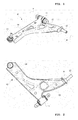
- Fig. 1 and Fig. 2 show an exemplary embodiment of a lower arm 10 among the components included in the vehicle suspension system of Macpherson type.
- the lower arm 10 has a first bush mounting part 11 and a second bush mounting part 12.
- a first arm 14 extends from the first bush mounting part 11 to a ball joint mounting part 13 at the other end, and a second arm 15 extends integrally from the first arm 14 so that it is connected to the second bush mounting part 12 at its end.
- first bush mounting part 11 and the second bush mounting part 12 spaced apart at front and rear are respectively mounted to a front member assembly of the vehicle chassis to be rotatable around horizontal axes of H and H'.
- the first arm 14 extrudes laterally from the vehicle chassis, and a ball joint (not shown) is mounted to the ball joint mounting part 13 which is connect to the end part of the first arm 14 to support the knuckle arm described above, so that the wheel mounting assembly can be rotatably supported.
- the manufacturing is difficult and delayed due to the welding processes of the parts. Also, defects are generated in the welding parts during the manufacturing process and cracks are generated in use thus decreasing durability.
- the overall weight of the lower arm 10 increases because the additional members 11 and 14 are attached by welding.
- the present invention provides a lower arm for vehicle suspension system comprising a first bush mounting part and a second bush mounting part mounted to a front member mounting assembly of a vehicle chassis to be spaced apart therebetween at front and rear, a first arm having one end part connected to the first bush mounting part and the other end part extruding laterally from the vehicle chassis to be connected to a ball joint mounting part to support a wheel mounting assembly, and a second arm having one end part extending integrally from the first arm and the other end part connected to the second bush mounting part, wherein the first arm is formed by forming a metal plate, the one end part of the first arm connected to the first bush mounting part has a pair of ring members which are formed by forming the metal plate to be parallel therebetween in an axial direction and to contact and support through their inner round surfaces an outer round surface of the first bush mounting part. Welding parts are removed in the manufacturing process
- a first holder sleeve extends from one of a pair of the ring members in the axial direction to contact and support the outer round surface of the first bush mounting part.
- a second holder sleeve extends from the other of a pair of the ring members in the axial direction to contact and support the outer round surface of the first bush mounting part.
- the first holder sleeve and the second holder sleeve extend in the same axial direction or in the opposite axial direction therebetween.
- the second arm is formed by forming the metal plate together with the first arm, and the second bush mounting part is comprised as a part of the second arm by forming the other end part of the second arm into a round shape.
- the second bush mounting part has a stopper sleeve and a bush sleeve having a smaller diameter than the stopper sleeve which are formed in order in the axial direction at the other end part of the second arm.
- the bush sleeve is inserted into the bush via a predetermined elastic member to elastically supports the bush, and at least a part of the stopper sleeve is inserted into the bush to be spaced apart from an inner surface of the bush by a predetermined gap so that limit of a radial fluctuation of the bush is restricted.
- the present invention also provides a lower arm for vehicle suspension system comprising a first bush mounting part and a second bush mounting part mounted to a front member mounting assembly of a vehicle chassis to be spaced apart therebetween at front and rear, a first arm having one end part connected to the first bush mounting part and the other end part extruding laterally from the vehicle chassis to be connected to a ball joint mounting part to support a wheel mounting assembly, and a second arm having one end part extending integrally from the first arm and the other end part connected to the second bush mounting part, wherein the second arm is formed by forming a metal plate, and the second bush mounting part is comprised as a part of the second arm by forming the other end part of the second arm into a round shape.
- welding parts are removed in the manufacturing process, so that easy manufacturing compared to the conventional art can be accomplished and high strength and weight reduction compared to the conventional art can also be accomplished.
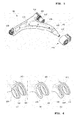
- a lower arm for vehicle suspension system 100 has a first bush mounting part 110 and a second bush mounting part 120 at front and rear, a first arm 101 extending from the first bush mounting part 110 to a ball joint mounting part 130, and a second arm 106 extending integrally from the first arm 101 to be connected to the second bush mounting part 120.
- first arm 101 and the second arm 106 are formed integrally by forming a single steel plate.
- an end part of the first arm 101 which is connected to the first bush mounting part 110 is formed into a pair of ring members 102 and 103 as shown in Fig. 5 and Fig. 6 (a) .
- a pair of the ring members 102 and 103 are formed spaced apart therebetween in the axial direction and contact and support an outer round surface of the first bush mounting part 110 through their inner round surfaces.
- the ring members 102 and 103 have holder sleeves 104 and 105 extending from the inner round surfaces in the axial direction so that the outer round surface of the first bush mounting part 110 is contacted and supported by the holder sleeves 104 and 105.
- the holder sleeves 104, 105 are explained to extend from both ring members 102, 103 in this embodiment, the present invention is not limited to such constitution.
- the holder sleeve 105 may be formed only at either one of the ring members 102, 103 as shown in Fig. 6 (b) or there may be no holder sleeves formed at the ring members 102, 103.
- the holder sleeves 104, 105 may be formed to extend in the same axial direction as shown in Fig. 6 (a) , or they may be formed to extend in the opposite axial direction as shown in Fig. 6 (c) .
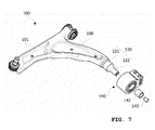
- the lower arm for vehicle suspension system 100 has the second bush mounting part 120 to be comprised as a part of the second arm 106.
- the second bush mounting part 120 is formed by forming a free end part of the second arm 106 into a round shape while the second arm 106 is being formed.
- a bush 140 is supported by being inserted into the second bush mounting part 120 which has been formed into the round shape.
- the bush 140 according to this exemplary embodiment is inserted by an elastic member 141 on its inner round surface to absorb impact and the second bush mounting part 120 is inserted into the elastic member 141, so that the bush 140 is elastically supported by the second bush mounting part 120 via the elastic member 141.
- the second bush mounting part 120 has a stopper sleeve 121 and a bush sleeve 122 which are formed in order at the above free end of the second arm 106.
- the stopper sleeve 121 has a comparably big diameter and the bush sleeve 122 has a smaller diameter compared to the stopper sleeve 121 so that the stress transferred between the second arm 106 and the bush 140 can be supported through the stopper sleeve 121. Therefore, the second bush mounting part 120 can be prevented from being broken down due to the stress to be concentrated at the second bush mounting part 120.
- the bush sleeve 122 is inserted into the elastic member 141 via a steel bush 142 to support the bush 140.
- a fastener 143 is inserted from an axial end part of the bush sleeve 122.
- the stopper sleeve 121 is a component not only for preventing breakdown of the second bush mounting part 120 due to the stress concentration as described above, but also performing function of restricting a radial fluctuation limit of the bush 140 with its end part inserted into the bush 140 by making a predetermined gap G which is formed in the radial direction between the stopper sleeve 121 and the elastic member 141 inserted into the bush 140. Therefore, an excessive vibration due to the impact from the tire can be prevented from transferring to the vehicle chassis.
- the present invention is not limited to such constitution, for example, as shown in Fig. 8 (b) , the fastener 143 may not be inserted into the bush sleeve.
- the steel bush 142' may be provided to be inserted within the elastic member 141'.
Applications Claiming Priority (1)
| Application Number | Priority Date | Filing Date | Title |
|---|---|---|---|
| KR1020130066214A KR101427079B1 (ko) | 2013-06-11 | 2013-06-11 | 자동차 현가장치용 로어아암 |
Publications (1)
| Publication Number | Publication Date |
|---|---|
| EP2813381A1 true EP2813381A1 (en) | 2014-12-17 |
Family
ID=50112807
Family Applications (1)
| Application Number | Title | Priority Date | Filing Date |
|---|---|---|---|
| EP14155398.2A Withdrawn EP2813381A1 (en) | 2013-06-11 | 2014-02-17 | Lower arm for a vehicle suspension system |
Country Status (4)
| Country | Link |
|---|---|
| US (1) | US20140361507A1 (ko) |
| EP (1) | EP2813381A1 (ko) |
| KR (1) | KR101427079B1 (ko) |
| CN (1) | CN104228503A (ko) |
Families Citing this family (32)
| Publication number | Priority date | Publication date | Assignee | Title |
|---|---|---|---|---|
| JP5842890B2 (ja) * | 2013-09-27 | 2016-01-13 | トヨタ自動車株式会社 | 車両の車体前部構造 |
| CN104553651B (zh) * | 2015-01-27 | 2018-03-23 | 安徽江淮汽车集团股份有限公司 | 下摆臂及汽车 |
| CN106466998A (zh) * | 2015-08-14 | 2017-03-01 | 浦项奥斯特姆(苏州)汽车配件有限公司 | 用于车辆悬挂系统的下臂 |
| DE102015115227A1 (de) * | 2015-09-10 | 2017-03-16 | Volkswagen Ag | Radführungslenker für ein Kraftfahrzeug |
| DE102016201457B4 (de) * | 2016-02-01 | 2024-04-11 | Ford Global Technologies, Llc | Verfahren zur Herstellung eines Aufhängungslenkers |
| DE102016123499A1 (de) * | 2016-12-05 | 2018-06-07 | Benteler Automobiltechnik Gmbh | Radlenker für eine Radaufhängung in einem Fahrzeug |
| DE102018128077A1 (de) * | 2018-11-09 | 2020-05-14 | Benteler Automobiltechnik Gmbh | Kraftfahrzeuglenker und Verfahren zur Herstellung eines Kraftfahrzeuglenkers |
| USD905799S1 (en) * | 2019-06-27 | 2020-12-22 | Traxxas Lp | Model vehicle lower suspension arm |
| USD905798S1 (en) * | 2019-06-27 | 2020-12-22 | Traxxas Lp | Model vehicle upper suspension arm |
| USD923722S1 (en) | 2019-06-28 | 2021-06-29 | Traxxas Lp | Model vehicle pivoting axle carrier |
| USD923115S1 (en) * | 2019-06-28 | 2021-06-22 | Traxxas Lp | Model vehicle pivoting axle carrier holder |
| WO2021046302A1 (en) * | 2019-09-05 | 2021-03-11 | Multimatic Patentco Llc | Weldless vehicular suspension control arm |
| USD923116S1 (en) | 2019-09-10 | 2021-06-22 | Traxxas Lp | Model vehicle pivoting axle carrier |
| USD951150S1 (en) | 2019-10-31 | 2022-05-10 | Traxxas, L.P. | Model vehicle lower suspension arm |
| USD951149S1 (en) | 2019-10-31 | 2022-05-10 | Traxxas, L.P. | Model vehicle upper suspension arm |
| USD951151S1 (en) | 2019-10-31 | 2022-05-10 | Traxxas, L.P. | Model vehicle lower suspension arm |
| USD951148S1 (en) | 2019-10-31 | 2022-05-10 | Traxxas, L.P. | Model vehicle lower suspension arm |
| USD944901S1 (en) | 2019-12-06 | 2022-03-01 | Traxxas Lp | Model vehicle lower suspension arm |
| USD947957S1 (en) | 2019-12-11 | 2022-04-05 | Traxxas Lp | Model vehicle upper suspension arm |
| US11725691B2 (en) | 2020-03-09 | 2023-08-15 | Steering Solutions Ip Holding Corporation | Hemispherical bushing assembly |
| USD947958S1 (en) | 2020-11-02 | 2022-04-05 | Traxxas Lp | Model vehicle pivoting axle carrier holder |
| USD947290S1 (en) | 2020-11-02 | 2022-03-29 | Traxxas Lp | Model vehicle axle carrier |
| USD947959S1 (en) | 2020-11-02 | 2022-04-05 | Traxxas Lp | Model vehicle pivoting axle carrier |
| USD1012789S1 (en) | 2021-05-13 | 2024-01-30 | Toyota Motor Engineering & Manufacturing North America, Inc. | Single piece upper control arm |
| USD1014657S1 (en) | 2021-11-16 | 2024-02-13 | Traxxas, L.P. | Model vehicle pivoting axle carrier |
| USD1014655S1 (en) | 2021-11-16 | 2024-02-13 | Traxxas, L.P. | Model vehicle suspension arm |
| USD996528S1 (en) | 2021-11-16 | 2023-08-22 | Traxxas, L.P. | Model vehicle axle carrier |
| USD1014656S1 (en) | 2021-11-16 | 2024-02-13 | Traxxas, L.P. | Model vehicle suspension arm |
| USD1014658S1 (en) | 2021-11-16 | 2024-02-13 | Traxxas, L.P. | Model vehicle pivoting axle carrier holder |
| USD1025846S1 (en) * | 2022-02-15 | 2024-05-07 | Arctic Cat, Inc. | Spindle for a recreational vehicle |
| USD1018382S1 (en) | 2022-09-07 | 2024-03-19 | Traxxas, L.P. | Model vehicle differential cover |
| USD1019480S1 (en) | 2022-09-08 | 2024-03-26 | Traxxas, L.P. | Model vehicle differential cover |
Citations (7)
| Publication number | Priority date | Publication date | Assignee | Title |
|---|---|---|---|---|
| JPH09155446A (ja) * | 1995-12-01 | 1997-06-17 | Toyota Motor Corp | 湾曲中空パイプの製造方法 |
| KR20020090497A (ko) | 2001-05-28 | 2002-12-05 | 현대자동차주식회사 | 로어아암의 저더 저감장치 |
| DE102007060963B3 (de) * | 2007-12-14 | 2009-04-09 | Benteler Automobiltechnik Gmbh | Verfahren zur Herstellung einer Achskomponente |
| DE102008015393A1 (de) * | 2008-03-20 | 2009-09-24 | Thyssenkrupp Umformtechnik Gmbh | Verfahren zum Herstellen eines Lenkers aus Blech |
| US20110198821A1 (en) * | 2010-02-12 | 2011-08-18 | Benteler Automobiltechnik Gmbh | Control arm, and method of producing a control arm |
| FR2956359A1 (fr) * | 2010-02-12 | 2011-08-19 | Benteler Automobiltechnik Gmbh | Bras oscillant transversal muni d'un tourillon, pour le montage sur un essieu de vehicule automobile, et procede de fabrication dudit bras |
| WO2013094580A1 (ja) * | 2011-12-21 | 2013-06-27 | 本田技研工業株式会社 | サスペンションアーム取付構造 |
Family Cites Families (14)
| Publication number | Priority date | Publication date | Assignee | Title |
|---|---|---|---|---|
| JPH0737201B2 (ja) * | 1991-12-10 | 1995-04-26 | マスコ インダストリーズ, インコーポレーテッド | 車両の懸架システム用制御アーム |
| JP3518199B2 (ja) * | 1996-10-02 | 2004-04-12 | 日産自動車株式会社 | サスペンション構造 |
| US6070445A (en) * | 1997-10-29 | 2000-06-06 | Trw Inc. | Method of manufacturing the control arm |
| DE10029189A1 (de) * | 2000-06-19 | 2001-12-20 | Fischer Georg Fahrzeugtech | Querlenker einer Radaufhängung |
| US6851687B2 (en) * | 2002-11-26 | 2005-02-08 | Daimlerchrysler Corporation | Off-axis cam adjustment system and method |
| DE602006020730D1 (de) * | 2005-07-18 | 2011-04-28 | Magna Int Inc | Steuerarm und achsschenkelanordnung |
| US20080284205A1 (en) * | 2007-05-16 | 2008-11-20 | Z F Group North American Operations, Inc. | Structural component |
| CA2611281A1 (en) * | 2007-11-20 | 2009-05-20 | Multimatic Inc. | Structural i-beam automotive suspension arm |
| JP2010111226A (ja) * | 2008-11-05 | 2010-05-20 | F Tech:Kk | 車両用l型サスペンションアーム |
| JP5363065B2 (ja) * | 2008-11-05 | 2013-12-11 | 株式会社エフテック | 車両用l型サスペンションアーム |
| DE102009006356B4 (de) * | 2009-01-28 | 2012-04-26 | Zf Friedrichshafen Ag | Querlenker eines Kraftfahrzeuges |
| CN201587297U (zh) * | 2009-12-29 | 2010-09-22 | 浙江吉利汽车研究院有限公司 | 汽车前悬架下摆臂与副车架之间的连接装置 |
| CN201604489U (zh) * | 2010-01-28 | 2010-10-13 | 宁波跃进汽车前桥有限公司 | 一种汽车悬架后托臂结构 |
| CN201751219U (zh) * | 2010-07-15 | 2011-02-23 | 浙江吉利汽车研究院有限公司 | 一种汽车前悬架下摆臂总成 |
-
2013
- 2013-06-11 KR KR1020130066214A patent/KR101427079B1/ko active IP Right Grant
-
2014
- 2014-02-17 EP EP14155398.2A patent/EP2813381A1/en not_active Withdrawn
- 2014-03-04 US US14/196,934 patent/US20140361507A1/en not_active Abandoned
- 2014-06-11 CN CN201410257932.4A patent/CN104228503A/zh active Pending
Patent Citations (7)
| Publication number | Priority date | Publication date | Assignee | Title |
|---|---|---|---|---|
| JPH09155446A (ja) * | 1995-12-01 | 1997-06-17 | Toyota Motor Corp | 湾曲中空パイプの製造方法 |
| KR20020090497A (ko) | 2001-05-28 | 2002-12-05 | 현대자동차주식회사 | 로어아암의 저더 저감장치 |
| DE102007060963B3 (de) * | 2007-12-14 | 2009-04-09 | Benteler Automobiltechnik Gmbh | Verfahren zur Herstellung einer Achskomponente |
| DE102008015393A1 (de) * | 2008-03-20 | 2009-09-24 | Thyssenkrupp Umformtechnik Gmbh | Verfahren zum Herstellen eines Lenkers aus Blech |
| US20110198821A1 (en) * | 2010-02-12 | 2011-08-18 | Benteler Automobiltechnik Gmbh | Control arm, and method of producing a control arm |
| FR2956359A1 (fr) * | 2010-02-12 | 2011-08-19 | Benteler Automobiltechnik Gmbh | Bras oscillant transversal muni d'un tourillon, pour le montage sur un essieu de vehicule automobile, et procede de fabrication dudit bras |
| WO2013094580A1 (ja) * | 2011-12-21 | 2013-06-27 | 本田技研工業株式会社 | サスペンションアーム取付構造 |
Also Published As
| Publication number | Publication date |
|---|---|
| CN104228503A (zh) | 2014-12-24 |
| US20140361507A1 (en) | 2014-12-11 |
| KR101427079B1 (ko) | 2014-08-07 |
Similar Documents
| Publication | Publication Date | Title |
|---|---|---|
| EP2813381A1 (en) | Lower arm for a vehicle suspension system | |
| US7571918B2 (en) | Suspension arm for a vehicle | |
| US8356826B2 (en) | Suspension system for a vehicle | |
| EP3112193B1 (en) | Method for obtaining a suspension arm for automotive vehicles and suspension arm | |
| EP2960086B1 (de) | Radaufhängung | |
| US20220402324A1 (en) | Torque Rod for Vehicle Suspension | |
| EP2361794A1 (en) | Vehicle suspension assembly | |
| US8757649B2 (en) | Connecting strut | |
| US20110116731A1 (en) | Confined heavy duty bushing for high load applications | |
| CN107963168B (zh) | 用于车轮对齐的悬吊支架结构 | |
| CA2998268C (en) | Aircraft landing gear assembly | |
| KR20140057023A (ko) | 커플드 토션 빔 액슬 타입의 리어 현가장치 | |
| US8777245B2 (en) | Optimized wall thickness torque rod | |
| EP3228485B1 (en) | Axle suspension system with panhard rod and vehicle with axle suspension system | |
| US9776669B2 (en) | Chassis mount structure | |
| CN108454346A (zh) | 用于车辆的后桥悬架 | |
| KR102402049B1 (ko) | 시트 금속 몸체와 그것에 부착된 고체 헤드를 갖춘 아암을 포함하는 차량의 바퀴를 위한 서스펜션 장치 | |
| CN107901704A (zh) | 一种后桥支架、后桥支架装配总成结构及车辆 | |
| US11345203B2 (en) | Ball joint and hybrid suspension arm including same | |
| JP2004299663A (ja) | サスペンションアーム、鍛造サスペンション部材および鍛造金型 | |
| US11754114B2 (en) | Ball joint, stabilizer link, and ball joint manufacturing method | |
| CN211075422U (zh) | 一种后悬架梯形臂 | |
| JP2015223910A (ja) | サスペンションアームの締結部材 | |
| US11577569B2 (en) | Bushing snubber bracket | |
| CN108688421B (zh) | 后悬架用拖曳臂 |
Legal Events
| Date | Code | Title | Description |
|---|---|---|---|
| 17P | Request for examination filed |
Effective date: 20140217 |
|
| AK | Designated contracting states |
Kind code of ref document: A1 Designated state(s): AL AT BE BG CH CY CZ DE DK EE ES FI FR GB GR HR HU IE IS IT LI LT LU LV MC MK MT NL NO PL PT RO RS SE SI SK SM TR |
|
| AX | Request for extension of the european patent |
Extension state: BA ME |
|
| PUAI | Public reference made under article 153(3) epc to a published international application that has entered the european phase |
Free format text: ORIGINAL CODE: 0009012 |
|
| STAA | Information on the status of an ep patent application or granted ep patent |
Free format text: STATUS: THE APPLICATION IS DEEMED TO BE WITHDRAWN |
|
| 18D | Application deemed to be withdrawn |
Effective date: 20150618 |