EP2813331B1 - Vorrichtung zum Schneiden von Panele aus Karton in Streifen - Google Patents
Vorrichtung zum Schneiden von Panele aus Karton in Streifen Download PDFInfo
- Publication number
- EP2813331B1 EP2813331B1 EP14165104.2A EP14165104A EP2813331B1 EP 2813331 B1 EP2813331 B1 EP 2813331B1 EP 14165104 A EP14165104 A EP 14165104A EP 2813331 B1 EP2813331 B1 EP 2813331B1
- Authority
- EP
- European Patent Office
- Prior art keywords
- blades
- frame
- panels
- moving
- cutting
- Prior art date
- Legal status (The legal status is an assumption and is not a legal conclusion. Google has not performed a legal analysis and makes no representation as to the accuracy of the status listed.)
- Not-in-force
Links
Images


Classifications
-
- B—PERFORMING OPERATIONS; TRANSPORTING
- B26—HAND CUTTING TOOLS; CUTTING; SEVERING
- B26D—CUTTING; DETAILS COMMON TO MACHINES FOR PERFORATING, PUNCHING, CUTTING-OUT, STAMPING-OUT OR SEVERING
- B26D1/00—Cutting through work characterised by the nature or movement of the cutting member or particular materials not otherwise provided for; Apparatus or machines therefor; Cutting members therefor
- B26D1/01—Cutting through work characterised by the nature or movement of the cutting member or particular materials not otherwise provided for; Apparatus or machines therefor; Cutting members therefor involving a cutting member which does not travel with the work
- B26D1/547—Cutting through work characterised by the nature or movement of the cutting member or particular materials not otherwise provided for; Apparatus or machines therefor; Cutting members therefor involving a cutting member which does not travel with the work having a wire-like cutting member
- B26D1/553—Cutting through work characterised by the nature or movement of the cutting member or particular materials not otherwise provided for; Apparatus or machines therefor; Cutting members therefor involving a cutting member which does not travel with the work having a wire-like cutting member with a plurality of wire-like cutting members
- B26D1/5535—Cutting through work characterised by the nature or movement of the cutting member or particular materials not otherwise provided for; Apparatus or machines therefor; Cutting members therefor involving a cutting member which does not travel with the work having a wire-like cutting member with a plurality of wire-like cutting members for thin material, e.g. for sheets, strips or the like
-
- B—PERFORMING OPERATIONS; TRANSPORTING
- B26—HAND CUTTING TOOLS; CUTTING; SEVERING
- B26D—CUTTING; DETAILS COMMON TO MACHINES FOR PERFORATING, PUNCHING, CUTTING-OUT, STAMPING-OUT OR SEVERING
- B26D1/00—Cutting through work characterised by the nature or movement of the cutting member or particular materials not otherwise provided for; Apparatus or machines therefor; Cutting members therefor
- B26D1/01—Cutting through work characterised by the nature or movement of the cutting member or particular materials not otherwise provided for; Apparatus or machines therefor; Cutting members therefor involving a cutting member which does not travel with the work
- B26D1/547—Cutting through work characterised by the nature or movement of the cutting member or particular materials not otherwise provided for; Apparatus or machines therefor; Cutting members therefor involving a cutting member which does not travel with the work having a wire-like cutting member
- B26D1/553—Cutting through work characterised by the nature or movement of the cutting member or particular materials not otherwise provided for; Apparatus or machines therefor; Cutting members therefor involving a cutting member which does not travel with the work having a wire-like cutting member with a plurality of wire-like cutting members
-
- B—PERFORMING OPERATIONS; TRANSPORTING
- B26—HAND CUTTING TOOLS; CUTTING; SEVERING
- B26D—CUTTING; DETAILS COMMON TO MACHINES FOR PERFORATING, PUNCHING, CUTTING-OUT, STAMPING-OUT OR SEVERING
- B26D7/00—Details of apparatus for cutting, cutting-out, stamping-out, punching, perforating, or severing by means other than cutting
- B26D7/06—Arrangements for feeding or delivering work of other than sheet, web, or filamentary form
- B26D7/0625—Arrangements for feeding or delivering work of other than sheet, web, or filamentary form by endless conveyors, e.g. belts
-
- B—PERFORMING OPERATIONS; TRANSPORTING
- B26—HAND CUTTING TOOLS; CUTTING; SEVERING
- B26D—CUTTING; DETAILS COMMON TO MACHINES FOR PERFORATING, PUNCHING, CUTTING-OUT, STAMPING-OUT OR SEVERING
- B26D7/00—Details of apparatus for cutting, cutting-out, stamping-out, punching, perforating, or severing by means other than cutting
- B26D7/26—Means for mounting or adjusting the cutting member; Means for adjusting the stroke of the cutting member
- B26D7/2628—Means for adjusting the position of the cutting member
Definitions
- the present invention relates to an apparatus for cutting cardboard panels into strips to be used in the packaging sector.
- the invention is related to an apparatus which makes it possible to cut any corrugated cardboard panel into strips of any dimension in a precise and efficient manner, avoiding at the same time the production of dross and dust residues which collect into the corrugations of the same panels.
- a widely used material is polystyrene in the form of pellets or strips or panels of various dimensions.
- polystyrene needs differentiated disposal and absolutely it is not an eco-friendly material.
- the eco-friendly material par excellence is cardboard.
- cardboard thanks to its corrugated structure and to its natural origin, cardboard meets both strength requirements necessary to ensure a very good functionality as a filler, and environmental requirements as it clearly derives from vegetal fibers.
- the blades are made with teeth which, while cutting, produce a product dross of 2-4 mm.
- dross is little important if singularly considered, but it becomes a great waste of material if, as it normally occurs, a panel of great dimensions is cut simultaneously by numerous blades to produce several strips at the same time.
- dross highly affects the finished product yield margins which are extremely reduced with respect to the cost of the raw material.
- Document DE 1628911 discloses a machine for cutting flat workpieces of wood comprising a moving system of one or more of said workpieces along a horizontal plane, a supporting structure for a gatter of cutting tools and a motor for moving said one or more cutting tools, wherein said supporting structure for said cutting tools comprises a frame for bearing blades, which frame is mounted onto a supporting structure to allow alternatively sliding in one direction and in the opposite one of a plurality of blades.
- the technical problem at the basis of the present invention is therefore that of providing an apparatus capable of avoiding dross production and its transformation into dust gathering in the corrugations of the cardboard strips for packaging.
- a first object of the invention is then an apparatus for cutting corrugated cardboard panels into strips, as defined in claim 1.
- a further object of the invention is a method for cutting corrugated cardboard panels as defined in claim 13.
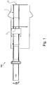
- FIG 1 it is shown a schematic plan view of a plant 100 for making strips of corrugated cardboard.
- the plant 100 comprises an apparatus 1 for cutting strips of corrugated cardboard provided with an entrance I of a corrugated cardboard panel and an exit O of corrugated cardboard strips after the transit of the panel in the apparatus 1.
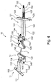
- the apparatus in its turn, comprises a moving system 2 (shown in figure 2 ) for one or more corrugated cardboard panels P, a plurality of blades 3 of the cutter type mounted on a frame 4, a supporting structure 5 of said frame 4 of the blades 3 ( figure 3 ).
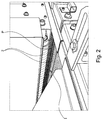
- the moving system comprises a couple of conveyor belts 2 apt at receiving a corrugated cardboard panel P in the entrance area I of the apparatus 1 and move it forward, that is in the opposed direction with respect to the entrance I, compacting it sandwich-like on both its two faces.
- the frame 4 ( figure 3 ) is a supporting structure which advantageously carries cutter type blades 3 and is made of a sort of castle comprising two horizontal and parallel crossbeams 41 A and 41 B and connected one to the other to the respective ends by means of corresponding uprights 42. In this way, it is formed a sort of rectangle defining a space occupied by the blade guides, as later described.
- the frame 4 in turn, is slidably mounted onto the supporting structure 5.
- the supporting structure 5 in fact, comprises a bridge 51 integral with a base 52, the latter anchored to the ground, preferably onto a concrete pour.
- On the base 52 it is fixed an electric motor 6 connected to an eccentric shaft 7 through a conventional transmission (not shown).
- the ends of the eccentric shaft 7 are connected to a connecting rod 8, which is then fixed to said upright 42 of the frame 4.
- the frame 4 is slidably mounted onto guides 53 fixed on the uprights of the bridge 51 so as to allow the moving forwards and backwards of the same frame towards one direction or towards the opposite direction.
- the frame 4 is mounted onto said supporting structure 5 in an inclined position with respect to its base 52 (shown in figure 3 ). Consequently, the movement forwards and backwards towards alternate opposite directions advantageously indeed occurs on an inclined plane with respect to the base.
- the frame 4 moves on a plane which is inclined with respect to the moving plane of the panel P, as later explained in detail. It has been seen that the blade inclination makes it possible to further reduce the amount of dross produced so as to basically eliminate it, as well as the problem of dust in the corrugations.
- the frame 4 is inclined of an angle comprised between 30° and 60° with respect to the moving plane of the panel P.
- this inclination degree allows the best cutting angle which reduces the stress and wearing out the blades 3 undergo and, therefore, it is advantageously increased their operating life.
- the device 10 comprises a first fixing element 11 and a second fixing element 12.
- the first fixing element 11 comprises a first fixing portion 111 to the upper crossbeam 41 A of the frame 4 and a second portion 112 for engagement with a first end of a blade 3, as later described.
- the first portion 111 is a longitudinal piece provided with two holes 113 for fixing with screws and nuts (not shown) to said crossbeam 41 A.
- the second portion 112 is T connected to the first portion and comprises a pin 114 for engagement with said first end of the blade 3.
- this pin 114 can be placed in at least two not aligned positions with respect to the longitudinal extension of said second portion.
- the second element 12 is T-shaped basically similar to that of the first element 11, that is, it comprises a first portion 121 for fixing to the lower crossbeam 41 B and a second portion 122 for engagement with a second end of the blade 3.
- the first portion 121 is provided with two through holes 123 for fixing to said crossbeam 41 B by means of screws and nuts. Further, it is preferably provided with a further hole engaged by a tensioning element 15 of the blade 3.
- the second portion 122 is longitudinally crossed by an inner groove 124 connected to said further hole.
- the tensioning element has a central body 151 apt at engaging said inner groove 124, a first end 152 protruding from said second portion 122 of the second element 12 and a second end 153 protruding from said first portion 121 still of the said second element 12.
- the first end 152 has a flat head carrying a pin 154 for connecting to a second end of the blade 3.
- said flat head has a surface extended enough so as to allow to place the pin 154 in at least two different not aligned positions with respect to the longitudinal extension of said tensioning element.
- the second end 153 comprises a threaded portion 155 whereon a nut 156 is screwed or unscrewed which makes it possible to adjust the blade 3 tensioning.
- the nut screwing causes the tensioning element to move, and therefore also of the first end 152 connected to the blade 3, in the traction direction of the same blade.
- unscrewing causes the traction release.
- a sleeve 157 provided with an elastic element, such as a spring, having the function of ensuring the correct tensioning of the blade and of absorbing possible side or transverse excess loads.
- the fixing device 10 of the blades 3 comprises guiding means apt at keeping each blade along a single straight line during the cutting operation.
- the apparatus 1 also comprises a supporting structure 9 for the above said guiding elements 13, 14 of blades 3.
- This structure 9 ( figure 3 ) is preferably composed of a first element 91 and of a second element 92.
- the first element 91 is a sort of table, fixed to the ground or to the base 52, whereon it is made to slide the panel P coming from the entrance I of the apparatus 1.
- One edge 911 of such table is placed in the space defined by the frame 4 and has a housing seat 912 for the first element 13 of said guiding means.
- said seat is shaped step-like, as better shown in figure 5 .
- the second element 92 is a sort of bar extending horizontally between the uprights of the bridge 52 and fixed to them.
- the bar is positioned on the upper part and at a certain distance from the edge 911 of the first element 91.
- this bar 92 and the edge 911 are basically aligned along the vertical (axis) so as to practically be in the space defined by the frame 4.
- this bar 92 comprises a track 913 (shown in figure 5 ) whereon the second element 14 of said guiding elements are mounted.
- each end of the bar 92 is connected to the uprights of the bridge 51 by means of a sliding guide (not shown) operated by a manual or automated mechanism in order to make it possible its moving away or close with respect to the edge 911 of the table 91 of the structure 9.
- a sliding guide (not shown) operated by a manual or automated mechanism in order to make it possible its moving away or close with respect to the edge 911 of the table 91 of the structure 9.
- Such mechanism is, for example, formed by a screw 914 manually operated by a rod 915 ( figure 5 ).
- the guiding elements are, for example, a first 13 and a second 14 guiding element.
- the first guiding element 13 is provided with an anchoring portion 131 to the edge 911 of the table 91 of the support 9 of the guiding elements and a guiding portion 132 of the blade 3.
- the anchoring portion 131 comprises a groove 133 for the engagement to a corner (not shown) of the seat 911 of the edge 91 and clamping elements 134 to anchor said first guiding element on said edge 91.
- These clamping elements 134 are formed by, for example, a plate provided with an engaging tooth, mounted on a screw provided with a nut so as to make it possible to adjust the plate blocking on a further corner (not shown) of the edge 91.
- the guiding portion 132 consists of two plates fixed to the anchoring portion 131 so as to define a groove 135 which is slidably engaged by a blade 3.
- the second guiding element 14 comprises an anchoring portion 141 to the bar 92 of the supporting structure 9 of the guiding means and a guiding portion 142 of a blade 3.
- the anchoring portion 141 comprises a groove 143 for engagement with a corner (not shown) of the bar 92 and clamping means 144 for anchoring said second guiding element onto said bar 92.
- clamping means 144 consist of, for example, a plate, provided with a engaging tooth, mounted on a screw provided with a nut so as to make it possible to adjust the plate blocking on a further corner (not shown) of the bar 92.
- the guiding portion 142 consists of two plates fixed to the anchoring portion 141 so as to define a groove 145 which is slidably engaged by a blade 3.
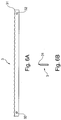
- the reference number 3 is referred to a blade of cutter type used in the apparatus 1 according to the present invention.
- the cutter blade 3 is a metal band having a longitudinal edge 31 whose transverse profile has a gradual thinning up ending in a point ( figure 6B ).
- said profile 31 has an undulating form with pointed apexes of the flutes.
- the bending radius of the flutes is comprised between 10 mm and 50 mm and the apex height is comprised between 3 mm and 5 mm.
- the maximum thickness of the blades is not higher than 0.9 mm, preferably it is between 0.5 mm and 0.8 mm. It results that the dross produced is practically reduced to zero.
- Such blades are preferably made of metal, preferably steel having a surface hardening treatment. It has been seen that this particular combination of the cutter blade characteristics makes it possible to fully reduce the formation of dust while cutting and at the same time, its wearing out with an operation life of more than 40 hours. Further, each of the blade ends has a hole 32 for engaging respectively with the pin 114 and 154 of the first 11 and second 12 fixing element of the blade to the frame 4 ( figure 4 ).
- the blades 3 are mounted on the frame 4 so as not to be aligned, in other words staged with respect to the cutting plane.
- adjacent blades are positioned onto two parallel but not aligned planes, one lower and the other higher, that is one nearer to the base 52 of the supporting structure 5 of the frame 4 and the other farther.
- the plant 100 preferably comprises a couple of motored conveyor belts 16 ( figure 10 ) placed in the proximity of the exit O of the apparatus 1 for cutting strips.
- These rolls 16 have the function of taking the just cut strips and, keeping them “sandwich” pressed, moving them forward to an unloading area of the plant 100.
- the strips exiting the apparatus 1 remain compact and do not undergo folds.
- the moving step occurs forwards and backwards along a plane inclined with respect to the horizontal moving forward plane of said panels.
- the corrugated cardboards provided can be of any shape, length, breadth and thickness traditionally on the market.
- they can be multilayered cardboards with a minimum thickness of 3 mm.
- the structure of the corrugations can be any of the known in the field, such as open flute, or for all kinds of available flutes: flute B (total cardboard thickness 3.0 mm), flute C (total cardboard 4.0 mm), flute EB (total cardboard 4.5 mm), flute BC (total cardboard 6.2 mm), flute CC (total cardboard 8.0 mm), flute AA (total cardboard 8.5 mm), as well as all undulating types of cardboard, 1, 2 or 3 fluted walls according to the FEFCO international classification.
- their breadth can vary from a minimum of 100 mm up to 1250 mm, while the height of a single cardboard or of a pack of cardboards can be for example up to a maximum of 150 mm.
- the moving forward step is carried out keeping the cardboard sandwich pressed, such as shown in figure 2 .
- the moving forward speed is comprised between 0.5 m per minute and 5 m per minute.
- the plurality of cutter blades is moved according to the above said alternate movement at a frequency comprised between 10 swing/second and 30 swing/second. Further, according to the preferred embodiment, as previously described, the inclination of the blades, and thus of the cut, with respect to the horizontal plane of the corrugated cardboard panel is comprised between 30° and 60°, as shown in figure 8 .
- the cutting step is preferably carried out positioning adjacent blades staged and separated one to the other in a variable manner along a longitudinal line, as shown in figure 9 .
- the method preferably also comprises a collecting step of the cut strips by moving forward and, at the same time, sandwich pressing the strips exiting the cutting step.
- Such collecting step is preferably carried out, as shown in figure 10 , by means of a motored conveyor belts.
- the apparatus and the method according to the invention make it possible to fully reduce the dross produced with traditional apparatuses provided with rotating or band blades and hence the waste of material. This entails a great saving in terms of material. At the same time, it is avoided the consequent cleaning of the dust which gathers in the corrugations of the strips.
- the pitch between the single blades is variable thanks to the possibility of mounting the respective supporting devices singularly along corresponding longitudinal structures. In this way, it is possible to contemporarily make strips of different width on the same panel. It is clear that this solution allows the greatest flexibility of the machine tooling and the optimization of the panel exploitation.
- the frame 4 of the blades makes it possible to adjust their inclination with respect to the horizontal plane so as to adapt the blade cutting capacity to the corrugated panel structure.
- the apparatus is capable of independently adjusting the moving forward speed of the panel to be cut, the swing frequency of the blades, the pitch of the blades, the distance between the first guiding element 13 and the second guiding element 14, the blade tensioning, all in order to optimize the cutting method.
- the thickness and/or the corrugation structure are respectively thin and wide then the moving forward speed will be high and the swing frequency of the blades will be low. The contrary will occur when the thickness and/or the corrugation structure will be respectively high and narrow.
- the force for moving the frame 4 of the blades can be obtained by non electric motors but internal combustion motors, or with mechanical vibration systems, ultrasound, magnetic induction motors, etc.
- the adjustment of the distance between the guiding elements 13 and 14 can occur electromechanically rather than manually.
- a control and command panel of the members of the device 10 can control and operate singularly said members in order to adjust their operation according to the specific cutting conditions. For example, operating and controlling the synchronous moving forward speed of the corrugated cardboard panel incoming and exiting the cutting apparatus 1, operating and controlling the swing frequency of the frame independently from the moving forward speed of the cardboard.
- the guiding elements 13 and 14 can have the guiding portion made en bloc milled so as to obtain the housing groove of the blade 3. Moreover, these same guiding elements can be fixed to the respective supports by means of traditional screws and nuts rather than plates with crimping teeth.
- each component of the fixing device 10 of the blades can be reduced to the purpose of mounting a greater number of blades 3 on the frame 4 and of being able to cut out of a single panel both a greater number of strips and a lower width for each strip.
- the plant 100 can further comprise a station for manually or automatically loading the cardboards to be cut for example taking them from a storage pallet.
- the loading can be automated so as to select the type and number of panels to load both side-by-side and stacked.
- the loading station can be provided a station for the transverse sectioning of the panel before cutting it into strips in order to determine their final length.
- an automated or manual taping machine for the binding or strapping of the bundle of strips.
- the bundles of bound or strapped strips can go into a cutting machine for the right length sectioning of the strips.
Landscapes
- Life Sciences & Earth Sciences (AREA)
- Forests & Forestry (AREA)
- Engineering & Computer Science (AREA)
- Mechanical Engineering (AREA)
- Control And Other Processes For Unpacking Of Materials (AREA)
- Making Paper Articles (AREA)
Claims (15)
- Vorrichtung (1) zum Schneiden von Wellkartonplatten (P), mit einem System zum Transportieren (2) einer oder mehrerer der Platten (P) entlang einer horizontalen Ebene, einer Haltestruktur (4) mit einem oder mehreren Schneidewerkzeugen (3) und einem Motor (6) zum Verschieben des einen oder der mehreren Schneidewerkzeuge, dadurch gekennzeichnet, dass die Haltestruktur (4) mit den Schneidewerkzeugen einen Rahmen (4), der Klingen (3) trägt, aufweist, wobei der Rahmen (4) abwechselnd ein Gleiten in einer Richtung und in der entgegengesetzten Richtung von mehreren Klingen (3), die vom Typ einer Schneide sind, ermöglicht, wobei die Klingen (3) eine Längskante (31) aufweisen, deren Querprofil eine graduelle zulaufende Verdünnung hat, die in einem Punkt mündet, wobei das Profil eine gewellte Form mit spitz zulaufenden Scheiteln der Rillen aufweist, wobei der Biegeradius der Rillen zwischen 3 mm und 5 mm liegt und wobei die maximale Dicke der Klingen nicht größer als 0,9 mm ist.
- Vorrichtung (1) nach Anspruch 1, wobei das Gleiten des Rahmens (4) zum Tragen der Klingen rückwärts und vorwärts entlang einer geneigten Ebene in Bezug auf die horizontale Ebene des Systems (2) ausgeführt wird, um die Platten so zu transportieren, dass die mehreren Klingen (3) des Schneidetyps einen geneigten Schnitt in Bezug auf die horizontale Ebenenfläche der Platte (P) ausführen.
- Vorrichtung (1) nach Anspruch 1 oder 2, wobei das Transportsystem (2) mehrere Transportbänder aufweist, die ausgebildet sind, zwischen ihnen eine oder mehrere der Platten (P) zu transportieren, während ein Verdichtungsdruck ausgeübt wird.
- Vorrichtung (1) nach einem der Ansprüche 1 bis 3, wobei der Rahmen (4) zwei parallele und horizontale Querstreben (41 A, 41 B) aufweist, die mit jeweiligen Enden mittels vertikaler Säulen (42) verbunden sind, wobei die mehreren Klingen (3) zwischen den zwei Querstreben mittels einer Befestigungseinrichtung (10) montiert sind.
- Vorrichtung (1) nach Anspruch 4, wobei die beiden Querstreben (41 A, 41 B) des Rahmens (4) über ihre jeweiligen Enden mittels Säulen (42), die vertikal geneigt sind, miteinander verbunden sind, und somit die mehreren Klingen (3) zwischen den zwei Querstreben mittels der Befestigungseinrichtung (10) so angeordnet sind, dass die Klingen vertikal geneigt und parallel zueinander sind.
- Vorrichtung (1) nach Anspruch 4, wobei die Befestigungseinrichtung (10) ein erstes Element (11) mit einem ersten Teil (111) zur Befestigung an der oberen Querstrebe (41 A) des Rahmens (4) und mit einem zweiten Teil (112) zum Eingriff mit einem ersten Ende einer Klinge (3) und ein zweites Element (12) mit einem ersten Teil (121) zur Befestigung an der unteren Querstrebe (41 B) des Rahmens (4) und mit einem zweiten Teil (122) zum Eingriff in ein zweites Ende der Klinge (3) aufweist.
- Vorrichtung (1) nach Anspruch 6, wobei das zweite Befestigungselement (12) ferner ein Spannelement (15) einer Klinge (3) aufweist.
- Vorrichtung (1) nach einem der Ansprüche 1 bis 7, wobei die Struktur (5) zum Halten des Rahmens (4) eine Brücke (51) aufweist, die mit Pfosten versehen ist, auf denen Führungen (53) befestigt sind, die das Gleiten des Rahmens ermöglichen.
- Vorrichtung (1) nach einem der Ansprüche 1 bis 8, wobei der Rahmen (4) sich auf der Haltestruktur (5) entlang einer Ebene bewegt, die 30° bis 60° in Bezug auf die horizontale Bewegungsebene der Platte (P) geneigt ist.
- Vorrichtung (1) nach einem der Ansprüche 1 bis 9, die ferner eine Haltestruktur (9) aus Führungseinrichtungen (13, 14) aufweist, wobei die Einrichtungen ausgebildet sind, jede Klinge (3) während des Schneidens entlang einer geraden Linie zu halten.
- Vorrichtung (1) nach Anspruch 10, wobei die Haltestruktur (9) ein erstes Element (91) zum Halten eines ersten Führungselements (13) und ein zweites Element (92) zum Halten eines zweiten Führungselements (14) aufweist, wobei der Abstand zwischen dem ersten (91) und dem zweiten (92) Halteelement verstellbar ist, um das erste (13) und das zweite (14) Führungselement einander anzunähern oder voneinander zu entfernen.
- Vorrichtung (1) nach Anspruch 11, wobei das erste (13) und das zweite (14) Führungselement jeweils einen Ankerbereich (131; 141) entsprechend für das zweite Halteelement (92) und das erste Halteelement (91) aufweisen, und wobei ein Führungsbereich (132; 142) mit einer Nut (135; 145) für einen gleitenden Eingriff der Klinge (3) versehen ist.
- Verfahren zum Schneiden von Wellkartonplatten, mit den Schritten:a) Bereitstellen einer oder mehrerer Wellkartonplatten, die letztlich gestapelt sind;b) Transportieren der einen oder mehreren Platten auf einer horizontalen Ebene nach vorne in Richtung zu mehreren Schneideklingen, wobei die eine oder die mehreren Platten durch Druck als Schichtanordnung beibehalten werden, wobei die Klingen eine Längskante (31) aufweisen, deren Querprofil eine graduelle zulaufende Verdünnung hat, die in einem Punkt mündet, wobei das Profil eine Wellenform mit spitz zulaufenden Scheiteln der Rillen aufweist, wobei der Biegeradius zwischen 3 mm und 5 mm liegt und die maximale Dicke der Klingen nicht größer als 0,9 mm ist;c) Transportieren mehrerer Schneideklingen parallel zueinander abwechselnd in eine Richtung und in die entgegengesetzte Richtung;d) Schneiden der Platte zu Streifen.
- Verfahren nach Anspruch 13, wobei der Schritt c) des Transportierens mehrerer Schneideklingen vorwärts und rückwärts entlang einer geneigten Ebene in Bezug auf eine horizontale Bewegungsebene der Platten ausgeführt wird.
- Verfahren nach Anspruch 13 oder 14, wobei der Schritt des Transports nach vorne ausgeführt wird, während der Kanton durch Pressen als Schichtverbund beibehalten wird, wobei die Vorwärtsgeschwindigkeit zwischen 0,5 m pro Minute und 5 m pro Minute liegt, wobei die mehreren Schneideklingen entsprechend der abwechselnden Transportbewegung mit einer Frequenz zwischen 10 Schwingungen/Sekunde und 30 Schwingungen/Sekunde bewegt werden, wobei die Neigung der Klingen und somit des Schnitts in Bezug auf die horizontale Ebene der Kartonplatte zwischen 30° und 60° liegt, wobei der Schneideschritt vorzugsweise ausgeführt wird, indem benachbarte Klingen gestuft und getrennt voneinander in variabler Weise entlang einer Schneidelinienlängsrichtung positioniert werden.
Priority Applications (1)
| Application Number | Priority Date | Filing Date | Title |
|---|---|---|---|
| HRP20160701TT HRP20160701T1 (hr) | 2013-05-06 | 2016-06-20 | Uređaj za rezanje kartonskih ploča na trake |
Applications Claiming Priority (1)
| Application Number | Priority Date | Filing Date | Title |
|---|---|---|---|
| IT000025A ITPN20130025A1 (it) | 2013-05-06 | 2013-05-06 | Apparecchiatura per il taglio di pannelli di cartone in listelli |
Publications (2)
| Publication Number | Publication Date |
|---|---|
| EP2813331A1 EP2813331A1 (de) | 2014-12-17 |
| EP2813331B1 true EP2813331B1 (de) | 2016-03-30 |
Family
ID=48793450
Family Applications (1)
| Application Number | Title | Priority Date | Filing Date |
|---|---|---|---|
| EP14165104.2A Not-in-force EP2813331B1 (de) | 2013-05-06 | 2014-04-17 | Vorrichtung zum Schneiden von Panele aus Karton in Streifen |
Country Status (5)
| Country | Link |
|---|---|
| EP (1) | EP2813331B1 (de) |
| HR (1) | HRP20160701T1 (de) |
| IT (1) | ITPN20130025A1 (de) |
| LT (1) | LT2813331T (de) |
| PL (1) | PL2813331T3 (de) |
Families Citing this family (1)
| Publication number | Priority date | Publication date | Assignee | Title |
|---|---|---|---|---|
| CN108818721A (zh) * | 2018-06-06 | 2018-11-16 | 滁州博昊门业制造有限公司 | 一种pvc护栏切断收料机构 |
Family Cites Families (4)
| Publication number | Priority date | Publication date | Assignee | Title |
|---|---|---|---|---|
| BE529027A (de) * | 1953-05-23 | |||
| DE1628911A1 (de) * | 1967-12-01 | 1972-05-18 | Friedrich Sliweczka | Vollgatter |
| JP2008062462A (ja) * | 2006-09-06 | 2008-03-21 | Iwasaki Metate Kakosho:Kk | チップソー |
| IT1402287B1 (it) * | 2010-10-08 | 2013-08-28 | Rollmatic S R L | Macchina affettatrice per prodotti alimentari |
-
2013
- 2013-05-06 IT IT000025A patent/ITPN20130025A1/it unknown
-
2014
- 2014-04-17 PL PL14165104.2T patent/PL2813331T3/pl unknown
- 2014-04-17 EP EP14165104.2A patent/EP2813331B1/de not_active Not-in-force
- 2014-04-17 LT LTEP14165104.2T patent/LT2813331T/lt unknown
-
2016
- 2016-06-20 HR HRP20160701TT patent/HRP20160701T1/hr unknown
Also Published As
| Publication number | Publication date |
|---|---|
| HRP20160701T1 (hr) | 2016-07-29 |
| ITPN20130025A1 (it) | 2014-11-07 |
| PL2813331T3 (pl) | 2016-09-30 |
| LT2813331T (lt) | 2016-09-26 |
| EP2813331A1 (de) | 2014-12-17 |
Similar Documents
| Publication | Publication Date | Title |
|---|---|---|
| RU2676349C2 (ru) | Способ и машина для изготовления заготовок для коробок в соответствии с размером | |
| RU2413606C1 (ru) | Станок для резки логов бумаги | |
| US20100031798A1 (en) | Horizontal Band-Saw | |
| EP2813331B1 (de) | Vorrichtung zum Schneiden von Panele aus Karton in Streifen | |
| US20160167244A1 (en) | Device for cutting material sheets | |
| CN107283546A (zh) | 一种自动化木材切割开槽机 | |
| CN104647555B (zh) | 木衣架下料机 | |
| CN205415877U (zh) | 一种刀具左右可调的四面刨木机 | |
| CN209335678U (zh) | 一种交替式裁切机 | |
| RU2516781C1 (ru) | Способ обработки изделий из древесины поперек волокон в двух и более плоскостях различных форм поперечных сечений | |
| CN221494412U (zh) | 一种钢格板加工用切边机 | |
| CN211842240U (zh) | 一种瓦楞纸板模切机的上料端限位装置 | |
| CN110315800A (zh) | 一种用于在纸板上裁切v槽的生产设备及其工作方法 | |
| CN110342101A (zh) | 一种用于制成包装盒的轻质环保型纸板及用于纸板加工的v槽机 | |
| CN103552105A (zh) | 废弃塑料托盘肢解机 | |
| CN212216930U (zh) | 一种钢格板切头机 | |
| CA2871675C (en) | Device for machining leaf- or sheet-shaped goods | |
| US3844426A (en) | Method for cutting panels | |
| EP3530578B1 (de) | Verpackungsmaschine und zugehöriges betriebsverfahren | |
| EP2735930A2 (de) | Verfahren und Vorrichtung für die Fixmaßherstellung | |
| CN113681981A (zh) | 一种条盒香烟快速易撕线的全自动生产设备 | |
| CN219988597U (zh) | 一种纸箱生产用开槽机 | |
| CN220200861U (zh) | 一种高性能磷青铜带 | |
| CN220219859U (zh) | 一种包装纸箱生产纸板切缝装置 | |
| CN219566826U (zh) | 一种瓦楞纸板堆码机 |
Legal Events
| Date | Code | Title | Description |
|---|---|---|---|
| 17P | Request for examination filed |
Effective date: 20140417 |
|
| AK | Designated contracting states |
Kind code of ref document: A1 Designated state(s): AL AT BE BG CH CY CZ DE DK EE ES FI FR GB GR HR HU IE IS IT LI LT LU LV MC MK MT NL NO PL PT RO RS SE SI SK SM TR |
|
| AX | Request for extension of the european patent |
Extension state: BA ME |
|
| PUAI | Public reference made under article 153(3) epc to a published international application that has entered the european phase |
Free format text: ORIGINAL CODE: 0009012 |
|
| R17P | Request for examination filed (corrected) |
Effective date: 20150430 |
|
| RBV | Designated contracting states (corrected) |
Designated state(s): AL AT BE BG CH CY CZ DE DK EE ES FI FR GB GR HR HU IE IS IT LI LT LU LV MC MK MT NL NO PL PT RO RS SE SI SK SM TR |
|
| RIC1 | Information provided on ipc code assigned before grant |
Ipc: B26D 7/06 20060101ALN20151126BHEP Ipc: B26D 1/553 20060101AFI20151126BHEP Ipc: B26D 7/26 20060101ALN20151126BHEP |
|
| RIC1 | Information provided on ipc code assigned before grant |
Ipc: B26D 1/553 20060101AFI20151202BHEP Ipc: B26D 7/26 20060101ALN20151202BHEP Ipc: B26D 7/06 20060101ALN20151202BHEP |
|
| GRAP | Despatch of communication of intention to grant a patent |
Free format text: ORIGINAL CODE: EPIDOSNIGR1 |
|
| INTG | Intention to grant announced |
Effective date: 20160111 |
|
| GRAS | Grant fee paid |
Free format text: ORIGINAL CODE: EPIDOSNIGR3 |
|
| GRAA | (expected) grant |
Free format text: ORIGINAL CODE: 0009210 |
|
| AK | Designated contracting states |
Kind code of ref document: B1 Designated state(s): AL AT BE BG CH CY CZ DE DK EE ES FI FR GB GR HR HU IE IS IT LI LT LU LV MC MK MT NL NO PL PT RO RS SE SI SK SM TR |
|
| REG | Reference to a national code |
Ref country code: GB Ref legal event code: FG4D |
|
| REG | Reference to a national code |
Ref country code: CH Ref legal event code: EP |
|
| REG | Reference to a national code |
Ref country code: AT Ref legal event code: REF Ref document number: 784845 Country of ref document: AT Kind code of ref document: T Effective date: 20160415 |
|
| REG | Reference to a national code |
Ref country code: IE Ref legal event code: FG4D |
|
| REG | Reference to a national code |
Ref country code: DE Ref legal event code: R096 Ref document number: 602014001253 Country of ref document: DE |
|
| REG | Reference to a national code |
Ref country code: HR Ref legal event code: TUEP Ref document number: P20160701 Country of ref document: HR |
|
| REG | Reference to a national code |
Ref country code: FR Ref legal event code: PLFP Year of fee payment: 3 |
|
| REG | Reference to a national code |
Ref country code: HR Ref legal event code: ODRP Ref document number: P20160701 Country of ref document: HR Payment date: 20160712 Year of fee payment: 3 |
|
| REG | Reference to a national code |
Ref country code: NL Ref legal event code: FP |
|
| PG25 | Lapsed in a contracting state [announced via postgrant information from national office to epo] |
Ref country code: GR Free format text: LAPSE BECAUSE OF FAILURE TO SUBMIT A TRANSLATION OF THE DESCRIPTION OR TO PAY THE FEE WITHIN THE PRESCRIBED TIME-LIMIT Effective date: 20160701 Ref country code: NO Free format text: LAPSE BECAUSE OF FAILURE TO SUBMIT A TRANSLATION OF THE DESCRIPTION OR TO PAY THE FEE WITHIN THE PRESCRIBED TIME-LIMIT Effective date: 20160630 Ref country code: FI Free format text: LAPSE BECAUSE OF FAILURE TO SUBMIT A TRANSLATION OF THE DESCRIPTION OR TO PAY THE FEE WITHIN THE PRESCRIBED TIME-LIMIT Effective date: 20160330 |
|
| PGFP | Annual fee paid to national office [announced via postgrant information from national office to epo] |
Ref country code: DE Payment date: 20160621 Year of fee payment: 3 |
|
| REG | Reference to a national code |
Ref country code: HR Ref legal event code: T1PR Ref document number: P20160701 Country of ref document: HR |
|
| REG | Reference to a national code |
Ref country code: AT Ref legal event code: MK05 Ref document number: 784845 Country of ref document: AT Kind code of ref document: T Effective date: 20160330 |
|
| PG25 | Lapsed in a contracting state [announced via postgrant information from national office to epo] |
Ref country code: BE Free format text: LAPSE BECAUSE OF NON-PAYMENT OF DUE FEES Effective date: 20160430 Ref country code: SE Free format text: LAPSE BECAUSE OF FAILURE TO SUBMIT A TRANSLATION OF THE DESCRIPTION OR TO PAY THE FEE WITHIN THE PRESCRIBED TIME-LIMIT Effective date: 20160330 Ref country code: RS Free format text: LAPSE BECAUSE OF FAILURE TO SUBMIT A TRANSLATION OF THE DESCRIPTION OR TO PAY THE FEE WITHIN THE PRESCRIBED TIME-LIMIT Effective date: 20160330 |
|
| PGFP | Annual fee paid to national office [announced via postgrant information from national office to epo] |
Ref country code: FR Payment date: 20160627 Year of fee payment: 3 Ref country code: LV Payment date: 20160620 Year of fee payment: 3 |
|
| PG25 | Lapsed in a contracting state [announced via postgrant information from national office to epo] |
Ref country code: IS Free format text: LAPSE BECAUSE OF FAILURE TO SUBMIT A TRANSLATION OF THE DESCRIPTION OR TO PAY THE FEE WITHIN THE PRESCRIBED TIME-LIMIT Effective date: 20160730 Ref country code: EE Free format text: LAPSE BECAUSE OF FAILURE TO SUBMIT A TRANSLATION OF THE DESCRIPTION OR TO PAY THE FEE WITHIN THE PRESCRIBED TIME-LIMIT Effective date: 20160330 |
|
| PGFP | Annual fee paid to national office [announced via postgrant information from national office to epo] |
Ref country code: LT Payment date: 20160704 Year of fee payment: 3 |
|
| PG25 | Lapsed in a contracting state [announced via postgrant information from national office to epo] |
Ref country code: SM Free format text: LAPSE BECAUSE OF FAILURE TO SUBMIT A TRANSLATION OF THE DESCRIPTION OR TO PAY THE FEE WITHIN THE PRESCRIBED TIME-LIMIT Effective date: 20160330 Ref country code: PT Free format text: LAPSE BECAUSE OF FAILURE TO SUBMIT A TRANSLATION OF THE DESCRIPTION OR TO PAY THE FEE WITHIN THE PRESCRIBED TIME-LIMIT Effective date: 20160801 Ref country code: ES Free format text: LAPSE BECAUSE OF FAILURE TO SUBMIT A TRANSLATION OF THE DESCRIPTION OR TO PAY THE FEE WITHIN THE PRESCRIBED TIME-LIMIT Effective date: 20160330 Ref country code: AT Free format text: LAPSE BECAUSE OF FAILURE TO SUBMIT A TRANSLATION OF THE DESCRIPTION OR TO PAY THE FEE WITHIN THE PRESCRIBED TIME-LIMIT Effective date: 20160330 Ref country code: RO Free format text: LAPSE BECAUSE OF FAILURE TO SUBMIT A TRANSLATION OF THE DESCRIPTION OR TO PAY THE FEE WITHIN THE PRESCRIBED TIME-LIMIT Effective date: 20160330 |
|
| PGFP | Annual fee paid to national office [announced via postgrant information from national office to epo] |
Ref country code: PL Payment date: 20160713 Year of fee payment: 3 Ref country code: CZ Payment date: 20160623 Year of fee payment: 3 |
|
| REG | Reference to a national code |
Ref country code: SK Ref legal event code: T3 Ref document number: E 21543 Country of ref document: SK |
|
| PG25 | Lapsed in a contracting state [announced via postgrant information from national office to epo] |
Ref country code: BE Free format text: LAPSE BECAUSE OF FAILURE TO SUBMIT A TRANSLATION OF THE DESCRIPTION OR TO PAY THE FEE WITHIN THE PRESCRIBED TIME-LIMIT Effective date: 20160330 |
|
| PGFP | Annual fee paid to national office [announced via postgrant information from national office to epo] |
Ref country code: HR Payment date: 20160712 Year of fee payment: 3 |
|
| REG | Reference to a national code |
Ref country code: DE Ref legal event code: R097 Ref document number: 602014001253 Country of ref document: DE |
|
| REG | Reference to a national code |
Ref country code: IE Ref legal event code: MM4A |
|
| PG25 | Lapsed in a contracting state [announced via postgrant information from national office to epo] |
Ref country code: DK Free format text: LAPSE BECAUSE OF FAILURE TO SUBMIT A TRANSLATION OF THE DESCRIPTION OR TO PAY THE FEE WITHIN THE PRESCRIBED TIME-LIMIT Effective date: 20160330 |
|
| PGFP | Annual fee paid to national office [announced via postgrant information from national office to epo] |
Ref country code: SK Payment date: 20161011 Year of fee payment: 3 |
|
| PLBE | No opposition filed within time limit |
Free format text: ORIGINAL CODE: 0009261 |
|
| STAA | Information on the status of an ep patent application or granted ep patent |
Free format text: STATUS: NO OPPOSITION FILED WITHIN TIME LIMIT |
|
| 26N | No opposition filed |
Effective date: 20170103 |
|
| PG25 | Lapsed in a contracting state [announced via postgrant information from national office to epo] |
Ref country code: SI Free format text: LAPSE BECAUSE OF FAILURE TO SUBMIT A TRANSLATION OF THE DESCRIPTION OR TO PAY THE FEE WITHIN THE PRESCRIBED TIME-LIMIT Effective date: 20160330 Ref country code: IE Free format text: LAPSE BECAUSE OF NON-PAYMENT OF DUE FEES Effective date: 20160417 |
|
| REG | Reference to a national code |
Ref country code: DE Ref legal event code: R119 Ref document number: 602014001253 Country of ref document: DE |
|
| REG | Reference to a national code |
Ref country code: LT Ref legal event code: MM4D Effective date: 20170417 |
|
| REG | Reference to a national code |
Ref country code: HR Ref legal event code: PBON Ref document number: P20160701 Country of ref document: HR Effective date: 20170417 |
|
| REG | Reference to a national code |
Ref country code: CH Ref legal event code: PL |
|
| REG | Reference to a national code |
Ref country code: NL Ref legal event code: MM Effective date: 20170501 |
|
| REG | Reference to a national code |
Ref country code: SK Ref legal event code: MM4A Ref document number: E 21543 Country of ref document: SK Effective date: 20170417 |
|
| REG | Reference to a national code |
Ref country code: FR Ref legal event code: ST Effective date: 20171229 |
|
| PG25 | Lapsed in a contracting state [announced via postgrant information from national office to epo] |
Ref country code: FR Free format text: LAPSE BECAUSE OF NON-PAYMENT OF DUE FEES Effective date: 20170502 Ref country code: SK Free format text: LAPSE BECAUSE OF NON-PAYMENT OF DUE FEES Effective date: 20170417 Ref country code: CZ Free format text: LAPSE BECAUSE OF NON-PAYMENT OF DUE FEES Effective date: 20170417 Ref country code: NL Free format text: LAPSE BECAUSE OF NON-PAYMENT OF DUE FEES Effective date: 20170501 Ref country code: HR Free format text: LAPSE BECAUSE OF NON-PAYMENT OF DUE FEES Effective date: 20170417 Ref country code: DE Free format text: LAPSE BECAUSE OF NON-PAYMENT OF DUE FEES Effective date: 20171103 Ref country code: LT Free format text: LAPSE BECAUSE OF NON-PAYMENT OF DUE FEES Effective date: 20170417 |
|
| PG25 | Lapsed in a contracting state [announced via postgrant information from national office to epo] |
Ref country code: CH Free format text: LAPSE BECAUSE OF NON-PAYMENT OF DUE FEES Effective date: 20170430 Ref country code: LI Free format text: LAPSE BECAUSE OF NON-PAYMENT OF DUE FEES Effective date: 20170430 Ref country code: LV Free format text: LAPSE BECAUSE OF NON-PAYMENT OF DUE FEES Effective date: 20170417 |
|
| PG25 | Lapsed in a contracting state [announced via postgrant information from national office to epo] |
Ref country code: HU Free format text: LAPSE BECAUSE OF FAILURE TO SUBMIT A TRANSLATION OF THE DESCRIPTION OR TO PAY THE FEE WITHIN THE PRESCRIBED TIME-LIMIT; INVALID AB INITIO Effective date: 20140417 |
|
| PG25 | Lapsed in a contracting state [announced via postgrant information from national office to epo] |
Ref country code: LU Free format text: LAPSE BECAUSE OF NON-PAYMENT OF DUE FEES Effective date: 20160417 Ref country code: MT Free format text: LAPSE BECAUSE OF NON-PAYMENT OF DUE FEES Effective date: 20160430 Ref country code: CY Free format text: LAPSE BECAUSE OF FAILURE TO SUBMIT A TRANSLATION OF THE DESCRIPTION OR TO PAY THE FEE WITHIN THE PRESCRIBED TIME-LIMIT Effective date: 20160330 Ref country code: MK Free format text: LAPSE BECAUSE OF FAILURE TO SUBMIT A TRANSLATION OF THE DESCRIPTION OR TO PAY THE FEE WITHIN THE PRESCRIBED TIME-LIMIT Effective date: 20160330 Ref country code: MC Free format text: LAPSE BECAUSE OF FAILURE TO SUBMIT A TRANSLATION OF THE DESCRIPTION OR TO PAY THE FEE WITHIN THE PRESCRIBED TIME-LIMIT Effective date: 20160330 |
|
| PG25 | Lapsed in a contracting state [announced via postgrant information from national office to epo] |
Ref country code: BG Free format text: LAPSE BECAUSE OF FAILURE TO SUBMIT A TRANSLATION OF THE DESCRIPTION OR TO PAY THE FEE WITHIN THE PRESCRIBED TIME-LIMIT Effective date: 20160330 |
|
| PG25 | Lapsed in a contracting state [announced via postgrant information from national office to epo] |
Ref country code: AL Free format text: LAPSE BECAUSE OF FAILURE TO SUBMIT A TRANSLATION OF THE DESCRIPTION OR TO PAY THE FEE WITHIN THE PRESCRIBED TIME-LIMIT Effective date: 20160330 Ref country code: TR Free format text: LAPSE BECAUSE OF FAILURE TO SUBMIT A TRANSLATION OF THE DESCRIPTION OR TO PAY THE FEE WITHIN THE PRESCRIBED TIME-LIMIT Effective date: 20160330 Ref country code: PL Free format text: LAPSE BECAUSE OF NON-PAYMENT OF DUE FEES Effective date: 20170417 |
|
| GBPC | Gb: european patent ceased through non-payment of renewal fee |
Effective date: 20180417 |
|
| PG25 | Lapsed in a contracting state [announced via postgrant information from national office to epo] |
Ref country code: GB Free format text: LAPSE BECAUSE OF NON-PAYMENT OF DUE FEES Effective date: 20180417 |
|
| PGFP | Annual fee paid to national office [announced via postgrant information from national office to epo] |
Ref country code: IT Payment date: 20210416 Year of fee payment: 8 |
|
| PG25 | Lapsed in a contracting state [announced via postgrant information from national office to epo] |
Ref country code: IT Free format text: LAPSE BECAUSE OF NON-PAYMENT OF DUE FEES Effective date: 20220417 |