EP2812142B1 - Einschraubwerkzeug und werkzeugaufnahme für ein derartiges einschraubwerkzeug - Google Patents
Einschraubwerkzeug und werkzeugaufnahme für ein derartiges einschraubwerkzeug Download PDFInfo
- Publication number
- EP2812142B1 EP2812142B1 EP13702395.8A EP13702395A EP2812142B1 EP 2812142 B1 EP2812142 B1 EP 2812142B1 EP 13702395 A EP13702395 A EP 13702395A EP 2812142 B1 EP2812142 B1 EP 2812142B1
- Authority
- EP
- European Patent Office
- Prior art keywords
- tool
- screw
- conical
- receptacle
- thread
- Prior art date
- Legal status (The legal status is an assumption and is not a legal conclusion. Google has not performed a legal analysis and makes no representation as to the accuracy of the status listed.)
- Active
Links
Images

Classifications
-
- B—PERFORMING OPERATIONS; TRANSPORTING
- B25—HAND TOOLS; PORTABLE POWER-DRIVEN TOOLS; MANIPULATORS
- B25B—TOOLS OR BENCH DEVICES NOT OTHERWISE PROVIDED FOR, FOR FASTENING, CONNECTING, DISENGAGING OR HOLDING
- B25B23/00—Details of, or accessories for, spanners, wrenches, screwdrivers
- B25B23/02—Arrangements for handling screws or nuts
-
- B—PERFORMING OPERATIONS; TRANSPORTING
- B23—MACHINE TOOLS; METAL-WORKING NOT OTHERWISE PROVIDED FOR
- B23B—TURNING; BORING
- B23B31/00—Chucks; Expansion mandrels; Adaptations thereof for remote control
- B23B31/02—Chucks
- B23B31/10—Chucks characterised by the retaining or gripping devices or their immediate operating means
- B23B31/11—Retention by threaded connection
- B23B31/1107—Retention by threaded connection for conical parts
- B23B31/1115—Retention by threaded connection for conical parts using conical threads
-
- B—PERFORMING OPERATIONS; TRANSPORTING
- B23—MACHINE TOOLS; METAL-WORKING NOT OTHERWISE PROVIDED FOR
- B23B—TURNING; BORING
- B23B31/00—Chucks; Expansion mandrels; Adaptations thereof for remote control
- B23B31/02—Chucks
- B23B31/08—Chucks holding tools yieldably
-
- B—PERFORMING OPERATIONS; TRANSPORTING
- B23—MACHINE TOOLS; METAL-WORKING NOT OTHERWISE PROVIDED FOR
- B23B—TURNING; BORING
- B23B31/00—Chucks; Expansion mandrels; Adaptations thereof for remote control
- B23B31/02—Chucks
- B23B31/10—Chucks characterised by the retaining or gripping devices or their immediate operating means
- B23B31/11—Retention by threaded connection
-
- B—PERFORMING OPERATIONS; TRANSPORTING
- B23—MACHINE TOOLS; METAL-WORKING NOT OTHERWISE PROVIDED FOR
- B23B—TURNING; BORING
- B23B51/00—Tools for drilling machines
- B23B51/12—Adapters for drills or chucks; Tapered sleeves
-
- B—PERFORMING OPERATIONS; TRANSPORTING
- B23—MACHINE TOOLS; METAL-WORKING NOT OTHERWISE PROVIDED FOR
- B23C—MILLING
- B23C5/00—Milling-cutters
- B23C5/26—Securing milling cutters to the driving spindle
-
- B—PERFORMING OPERATIONS; TRANSPORTING
- B23—MACHINE TOOLS; METAL-WORKING NOT OTHERWISE PROVIDED FOR
- B23P—METAL-WORKING NOT OTHERWISE PROVIDED FOR; COMBINED OPERATIONS; UNIVERSAL MACHINE TOOLS
- B23P19/00—Machines for simply fitting together or separating metal parts or objects, or metal and non-metal parts, whether or not involving some deformation; Tools or devices therefor so far as not provided for in other classes
- B23P19/04—Machines for simply fitting together or separating metal parts or objects, or metal and non-metal parts, whether or not involving some deformation; Tools or devices therefor so far as not provided for in other classes for assembling or disassembling parts
- B23P19/06—Screw or nut setting or loosening machines
-
- B—PERFORMING OPERATIONS; TRANSPORTING
- B25—HAND TOOLS; PORTABLE POWER-DRIVEN TOOLS; MANIPULATORS
- B25B—TOOLS OR BENCH DEVICES NOT OTHERWISE PROVIDED FOR, FOR FASTENING, CONNECTING, DISENGAGING OR HOLDING
- B25B21/00—Portable power-driven screw or nut setting or loosening tools; Attachments for drilling apparatus serving the same purpose
-
- B—PERFORMING OPERATIONS; TRANSPORTING
- B23—MACHINE TOOLS; METAL-WORKING NOT OTHERWISE PROVIDED FOR
- B23B—TURNING; BORING
- B23B2231/00—Details of chucks, toolholder shanks or tool shanks
- B23B2231/24—Cooling or lubrication means
-
- B—PERFORMING OPERATIONS; TRANSPORTING
- B23—MACHINE TOOLS; METAL-WORKING NOT OTHERWISE PROVIDED FOR
- B23B—TURNING; BORING
- B23B2240/00—Details of connections of tools or workpieces
- B23B2240/24—Connections using hollow screws, e.g. for the transmission of coolant
-
- B—PERFORMING OPERATIONS; TRANSPORTING
- B23—MACHINE TOOLS; METAL-WORKING NOT OTHERWISE PROVIDED FOR
- B23B—TURNING; BORING
- B23B2260/00—Details of constructional elements
- B23B2260/138—Screw threads
- B23B2260/1381—Conical
-
- B—PERFORMING OPERATIONS; TRANSPORTING
- B23—MACHINE TOOLS; METAL-WORKING NOT OTHERWISE PROVIDED FOR
- B23C—MILLING
- B23C2210/00—Details of milling cutters
- B23C2210/02—Connections between the shanks and detachable cutting heads
-
- B—PERFORMING OPERATIONS; TRANSPORTING
- B23—MACHINE TOOLS; METAL-WORKING NOT OTHERWISE PROVIDED FOR
- B23C—MILLING
- B23C2240/00—Details of connections of tools or workpieces
- B23C2240/32—Connections using screw threads
-
- B—PERFORMING OPERATIONS; TRANSPORTING
- B23—MACHINE TOOLS; METAL-WORKING NOT OTHERWISE PROVIDED FOR
- B23C—MILLING
- B23C2250/00—Compensating adverse effects during milling
- B23C2250/12—Cooling and lubrication
-
- B—PERFORMING OPERATIONS; TRANSPORTING
- B23—MACHINE TOOLS; METAL-WORKING NOT OTHERWISE PROVIDED FOR
- B23C—MILLING
- B23C5/00—Milling-cutters
- B23C5/02—Milling-cutters characterised by the shape of the cutter
- B23C5/10—Shank-type cutters, i.e. with an integral shaft
- B23C5/1009—Ball nose end mills
-
- Y—GENERAL TAGGING OF NEW TECHNOLOGICAL DEVELOPMENTS; GENERAL TAGGING OF CROSS-SECTIONAL TECHNOLOGIES SPANNING OVER SEVERAL SECTIONS OF THE IPC; TECHNICAL SUBJECTS COVERED BY FORMER USPC CROSS-REFERENCE ART COLLECTIONS [XRACs] AND DIGESTS
- Y10—TECHNICAL SUBJECTS COVERED BY FORMER USPC
- Y10T—TECHNICAL SUBJECTS COVERED BY FORMER US CLASSIFICATION
- Y10T279/00—Chucks or sockets
- Y10T279/16—Longitudinal screw clamp
-
- Y—GENERAL TAGGING OF NEW TECHNOLOGICAL DEVELOPMENTS; GENERAL TAGGING OF CROSS-SECTIONAL TECHNOLOGIES SPANNING OVER SEVERAL SECTIONS OF THE IPC; TECHNICAL SUBJECTS COVERED BY FORMER USPC CROSS-REFERENCE ART COLLECTIONS [XRACs] AND DIGESTS
- Y10—TECHNICAL SUBJECTS COVERED BY FORMER USPC
- Y10T—TECHNICAL SUBJECTS COVERED BY FORMER US CLASSIFICATION
- Y10T408/00—Cutting by use of rotating axially moving tool
- Y10T408/44—Cutting by use of rotating axially moving tool with means to apply transient, fluent medium to work or product
- Y10T408/45—Cutting by use of rotating axially moving tool with means to apply transient, fluent medium to work or product including Tool with duct
-
- Y—GENERAL TAGGING OF NEW TECHNOLOGICAL DEVELOPMENTS; GENERAL TAGGING OF CROSS-SECTIONAL TECHNOLOGIES SPANNING OVER SEVERAL SECTIONS OF THE IPC; TECHNICAL SUBJECTS COVERED BY FORMER USPC CROSS-REFERENCE ART COLLECTIONS [XRACs] AND DIGESTS
- Y10—TECHNICAL SUBJECTS COVERED BY FORMER USPC
- Y10T—TECHNICAL SUBJECTS COVERED BY FORMER US CLASSIFICATION
- Y10T408/00—Cutting by use of rotating axially moving tool
- Y10T408/89—Tool or Tool with support
- Y10T408/909—Having peripherally spaced cutting edges
- Y10T408/9098—Having peripherally spaced cutting edges with means to retain Tool to support
- Y10T408/90993—Screw driven means
-
- Y—GENERAL TAGGING OF NEW TECHNOLOGICAL DEVELOPMENTS; GENERAL TAGGING OF CROSS-SECTIONAL TECHNOLOGIES SPANNING OVER SEVERAL SECTIONS OF THE IPC; TECHNICAL SUBJECTS COVERED BY FORMER USPC CROSS-REFERENCE ART COLLECTIONS [XRACs] AND DIGESTS
- Y10—TECHNICAL SUBJECTS COVERED BY FORMER USPC
- Y10T—TECHNICAL SUBJECTS COVERED BY FORMER US CLASSIFICATION
- Y10T408/00—Cutting by use of rotating axially moving tool
- Y10T408/94—Tool-support
- Y10T408/95—Tool-support with tool-retaining means
Definitions
- the invention relates to a screw-in tool according to the preamble of claim 1.
- the invention also relates to a tool holder for such a screw-in tool and a tool arrangement with screw-in tool and tool holder.
- a screw-in tool which contains a tool head and a tool shank with an external thread and a first support area arranged between the tool head and the external thread.
- the first support area is designed either as a radial collar with a flat surface and a cylindrical inner contact surface, or as a conical contact surface.
- precise axial positioning of the screwing-in tool within a receptacle is achieved via the planar surface of the radial collar, but the centering effect via the cylindrical contact surface is limited.
- the outer walls of the tool holders can deform outwards as a result of the wedge effect of the conical contact surface, which can have a negative effect on the axial alignment.
- FR 1 019 411 A discloses a tool holder head insertable into a spindle shaft for holding a tool releasably attached to a lower end of the tool holder head.
- the tool holding head has a tool shank with an external thread and a support area with a conical contact surface.
- a conical transition surface is provided between the conical contact surface and the thread.
- the conical contact surface of the tool head that comes into contact with the spindle shaft has a relatively small cone angle.
- a tool head provided with a conical locating pin is inserted into a tool holder provided with a conical locating bore and then pulled in axially with the aid of a clamping screw.
- One on the front end The conical contact surface adjacent to the tool holder and a corresponding conical contact surface on the tool head have a cone angle of approx. 85°.
- the DE 10 2009 048 010 B3 which discloses a screw-in tool according to the preamble of claim 1, discloses a tool head with a corresponding tool holder, wherein a tool interface is provided for coupling, which has a support area with two conical surfaces. To increase the flexibility of the tool interface, the support area is radially slotted. In order to prevent the tool interface from being damaged by the radial forces from the conical surfaces, it is necessary for the radial force acting on the tool interface to be balanced out by the conical surfaces. For this reason, the cones underlying the conic surfaces point in opposite directions.
- the object of the invention is to create a screw-in tool, a tool holder for such a screw-in tool and a tool arrangement with a tool holder and screw-in tool that enable a screw-in tool to be accommodated and held in a positionally accurate and reproducible manner.
- the support area arranged between the tool head and the external thread is formed by two conical contact surfaces with different cone angles.
- the support area arranged between a front end face of the tool holder and an internal thread is formed by two conical bearing surfaces with different cone angles. This creates a support area with a double cone, which enables an enlarged contact surface and an improved centering and supporting effect compared to a flat contact or a straight contact surface.
- an inner contact area designed as a cylindrical, spherical or conical contact surface is also provided at an inner end of the receiving opening.
- the diameter of the conical first bearing surface and the associated conical first contact surface decrease in the screwing-in direction of the tool, ie the cones on which the two conical surfaces forming the double cone are based point in the same direction.
- a slight spreading of the tool holder is possible due to the conical surfaces.
- the thread preload increases less with the screw-in angle and it is therefore possible to set the preload more precisely when assembling the screw-in tool. Since the screw-in tools are usually made in one piece from very hard materials, the elastic deformation of the thread necessary for locking the thread is largely limited to the deformation of the internal thread of the tool holder. With regard to the longest possible service life of such a tool holder, an exact setting of the thread preload is therefore extremely important.
- a double cone of the type described enables thread prestressing to be precise because it can be adjusted more easily.
- the first conical contact surface of the screw-in tool adjacent to the tool head and the associated conical first bearing surface on the end face of the tool holder preferably have a relatively large cone angle.
- a cone angle of 170° has proven to be favorable here.
- the second conical bearing surface adjoins this surface on the screw-in tool and the associated second conical bearing surface on the tool holder.
- This second bearing surface and the second contact surface corresponding thereto preferably have relatively small cone angles.
- a cone angle of 10° has proven to be favorable here exposed.
- a double cone of the type described with two different cone angles has the advantage that the small cone angle allows good centering of the screwing tool in the tool holder and the large cone angle allows additional centering but with greatly reduced spreading forces on the tool holder.
- the rigidity of the tool is increased by the conical first contact surface, since the tool cannot slide off under radial load, as is the case with a planar contact surface.
- a further support area with a contact area is provided at the free end of the tool shank.
- This additional contact area on the tool shank of the screw-in tool can be spherical, for example, while the associated additional contact area on the tool holder can be designed as a cylindrical contact surface. Due to the spherical contact area and the cylindrical bearing surface, only partial contact between the screw-in tool and the tool holder is achieved in this area. Expediently, the spherical additional contact area is oversized compared to the cylindrical bearing surface, so that the preload in this additional support area is independent of the screw-in depth.
- Spherical, conical or cylindrical contact surfaces or support surfaces can also be provided on the tool and the tool holder in any combination.
- the external thread on the screw-in tool and the corresponding internal thread on the tool holder expediently have a thread depth that decreases toward the free end of the tool shank or toward the inner end of the receiving opening.
- the threads can also have a constant thread depth.
- Trapezoidal threads or flat threads have proven to be particularly useful for the external thread and the corresponding internal thread.
- the threads can also be designed as pointed threads, round threads, buttress threads or the like.
- an insert bushing is provided, which is inserted into the tool holder.
- This insert can the bearing surfaces of the first and second support area and the thread, but only include some of these elements. Vibration damping can be achieved by choosing a suitable material for the insert bushing.
- the tool holder can also be made of solid but brittle hard metal and the insert bushing with the thread can be made of softer but rather elastic steel, which is favorable for secure locking of the screw connection.
- the tool holder can be adapted to accommodate different tool geometries using various insert bushes.
- the insert socket can consist of one part or of several parts, which can also consist of different materials.
- the tool holder can consist, for example, of steel, hard metal, aluminum or a fiber composite material, in particular with glass or carbon fibers.
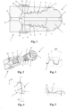
- FIG. 1 and 2 a tool arrangement with a screw-in tool 1 and an associated tool holder 2 is shown in a longitudinal section and a perspective view.
- the screw-in tool 1 has a tool head 3 embodied here as a spherical milling cutter and a tool shank 4 that tapers conically towards the rear and has an external thread 5 .
- a first support area with a first conical contact surface 6 for contact with a counter-conical contact surface 7 on a front end face of the tool holder 2 and a second conical contact surface 8 for contact with a second conical contact surface 9 inside the tool holder.
- a second support area 11 is located at a free rear end 10 of the tool shank 4.
- the tool head 3 has on its outside a plurality of wrench flats 12 distributed over the circumference for screwing the screw-in tool 1 into the tool holder 2 .
- the wrench flats 12 can also be used for automatic tool changes in the milling machine.
- a gripper groove 13 for automatically clamping the screw-in tool 1 in the tool holder 2 is provided in the rear area of the tool shank 4 .
- pliers-like gripper elements of a clamping device can engage in the gripper groove 13 in order to be able to securely grip or hold the screw-in tool 1 in the tool holder 2 .
- central through-opening 14 through which cooling lubricant, compressed air or another working fluid can be directed to the machining area.
- the passage opening 14 is arranged coaxially to the central axis 15 of the screwing tool 1, but other arrangements are also possible, for example with truly parallel or angled longitudinal axes.
- the tool holder 2 belonging to the screw-in tool 1 has a receiving opening 16 with an internal thread 17 .
- Radial bores 20 can also be arranged in the tool holder 2 , which open into the receiving opening 16 or also into the feed 19 .
- a sleeve 22 provided with an annular groove 21 on the inside for external coolant supply can be arranged on the outside of the tool holder 2 . However, the annular groove 21 can also be formed on the tool holder 2 .
- the external thread 5 of the screw-in tool 1 and the associated internal thread 17 of the tool holder 2 are trapezoidal threads with an in figure 3 illustrated flank angle of 30°.
- the external thread 5 of the screw-in tool 1 and the associated internal thread 17 of the tool holder 2 can also be designed as a trapezoidal thread with other flank angles.
- the external thread 5 used here has a thread depth that decreases from the tool head 3 to the free rear end 10 of the tool shaft 4 . Even with the internal thread 17 of Tool holder 2 decreases the thread depth from the second bearing surface 9 to the second support area 11 .
- first contact surface 6 of the screw-in tool 1 and the corresponding first contact surface 7 of the tool holder 2 are each inclined by 5° with respect to a plane perpendicular to the central axes 15 and 18 in the direction of the front end of the tool head 3.
- first conical bearing surface 6 and also the first conical bearing surface 7 have a cone angle of at least 140° and at most 179°, but preferably 170°.
- the diameter of the second conical contact surface 8 of the screwing tool 1 and the diameter of the second conical contact surface 9 of the tool holder 2 taper in the screwing-in direction, resulting in a cone angle of at least 1° and a maximum of 90°, but preferably 10°, which means an angle of the conical surfaces of 5° relative to the central axes 15 and 18.
- the second support area 11 of the screwing tool 1 is shown in FIG figure 5 spherical and comes into contact with a cylindrical contact surface 24 at the end of the receiving opening 16.
- the cylindrical contact surface 24 forms a further inner contact area in the tool holder.
- the spherical support area 11 ensures that there is only partial contact between the screw-in tool 1 and the tool holder 2.
- the spherical second support area 11 is expediently oversized compared to the cylindrical contact surface 24, so that the preload in this second support area is independent of the screw-in depth.
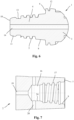
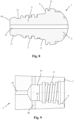
- FIG. 8 and 9 a further exemplary embodiment of a screw-in tool 1 and an associated tool holder 2 is shown.
- the external thread 5 of the screw-in tool 1 and the internal thread 17 of the tool holder 2 are designed as flat threads. Otherwise, this embodiment corresponds to the previous exemplary embodiment, so that components corresponding to one another are also provided with the same reference symbols.
- the external thread 5 used here has a thread depth that decreases from the tool head 3 to the free rear end 10 of the tool shank 4 . Furthermore, in the case of the internal thread 17 of the tool holder 2 , the thread depth also decreases here from the second contact surface 9 to the second support area 11 .
- the second conical bearing surface 8 and the second conical bearing surface 9 taper at an angle of 5° in relation to the central axes 15 and 18, resulting in a cone angle of 10°.
- the cones on which the two conical surfaces forming the double cone are based point in opposite directions.
- an insert bushing 25 which contains the second conical bearing surface 9, the internal thread 17 and the cylindrical contact surface 24, is inserted into the receiving opening 16 of the tool holder 2.
- the radial bores 20 go through the tool holder 2 and the insert bushing 25 and open into the receiving opening 16 of the tool holder 2.
- FIG 13 shows an enlarged view of the sleeve 22 for the external coolant supply.
- the sleeve 22 has one or more outlets 26 through which the coolant that is guided outwards via the radial bores 20 and emerges through the outer openings 23 can be directed to the tool or the point to be machined.
- the outlet or outlets 26 can be designed as a circumferential gap, bores, slots or the like.
Landscapes
- Engineering & Computer Science (AREA)
- Mechanical Engineering (AREA)
- Gripping On Spindles (AREA)
- Milling Processes (AREA)
- Jigs For Machine Tools (AREA)
- Drilling Tools (AREA)
- Details Of Spanners, Wrenches, And Screw Drivers And Accessories (AREA)
Description
- Die Erfindung betrifft ein Einschraubwerkzeug nach dem Oberbegriff des Anspruchs 1. Die Erfindung betrifft außerdem eine Werkzeugaufnahme für ein derartiges Einschraubwerkzeug und eine Werkzeuganordnung mit Einschraubwerkzeug und Werkzeugaufnahme.
- Aus der
WO 2006/033617 A1 ist ein Einschraubwerkzeug bekannt, das einen Werkzeugkopf und einen Werkzeugschaft mit einem Außengewinde und einem zwischen dem Werkzeugkopf und dem Außengewinde angeordneten ersten Abstützbereich enthält. Bei diesem bekannten Einschraubwerkzeug ist der erste Abstützbereich entweder als Radialbund mit einer Planfläche und einer zylindrischen inneren Anlagefläche oder als konische Anlagefläche ausgeführt. Bei der ersten Alternative wird über die Planfläche des Radialbund zwar eine genaue axiale Positionierung des Einsschraubwerkzeugs innerhalb einer Aufnahme erreicht, allerdings ist die Zentrierwirkung über die zylindrische Anlagefläche beschränkt. Über die konische Anlagefläche ist zwar eine bessere Zentrierwirkung erreichbar, jedoch können sich die Außenwände der Werkzeugaufnahmen infolge der Keilwirkung der konischen Anlagefläche nach außen verformen, was sich negativ auf die axiale Ausrichtung auswirken kann. - In der
FR 1 019 411 A - Bei einer aus der
DE 39 12 503 A1 bekannten Spanneinrichtung für auswechselbare Werkzeugköpfe wird ein mit einem kegeligen Aufnahmezapfen versehener Werkzeugkopf in einen mit einer kegeligen Aufnahmebohrung versehenen Werkzeughalter eingesteckt und anschließend mit Hilfe einer Spannschraube axial eingezogen. Eine an der vorderen Stirnseite des Werkzeughalters angrenzende kegelige Anlagefläche und eine entsprechende kegelige Anlagefläche am Werkzeugkopf weisen einen Kegelwinkel von ca. 85° auf. - Die
DE 10 2009 048 010 B3 , die ein Einschraubwerkzeug gemäß dem Oberbegriff des Anspruchs 1 offenbart, offenbart einen Werkzeugkopf mit einer korrespondierenden Werkzeugaufnahme, wobei zur Kupplung ein Werkzeuginterface vorgesehen ist, das einen Abstützbereich mit zwei konischen Flächen aufweist. Zur Erhöhung der Flexibilität des Werkzeuginterfaces ist der Abstützbereich radial geschlitzt. Um eine Beschädigung des Werkzeuginterfaces durch die Radialkräfte aus den konischen Flächen zu verhindern, ist es notwendig, dass die radiale Krafteinwirkung auf das Werkzeuginterface durch die konischen Flächen ausgeglichen wird. Aus diesem Grund zeigen die den konischen Flächen zugrundeliegenden Kegel in entgegengesetzte Richtungen. - Aus der
JP H05 318208 A - In der
US 2006/0051167 A1 ist eine Werkzeugaufnahme gemäß dem Oberbegriff des Anspruchs 9 mit einer konischen Aufnahmeöffnung für ein Werkzeug offenbart. Bei dieser Werkzeugaufnahme wird das Werkzeug jedoch in die konische Aufnahmeöffnung eingesteckt und durch eine gesonderte Schraube fixiert, die in ein am inneren Ende der Aufnahmeöffnung angeordnetes Innengewinde eingreift. - Aufgabe der Erfindung ist es, ein Einschraubwerkzeug, eine Werkzeugaufnahme für ein derartiges Einschraubwerkzeug und eine Werkzeuganordnung mit Werkzeugaufnahme und Einschraubwerkzeug zu schaffen, die eine positionsgenaue und reproduzierbare Aufnahme und Halterung eines Einschraubwerkzeugs ermöglichen.
- Diese Aufgabe wird durch ein Einschraubwerkzeug mit den Merkmalen des Anspruchs 1, durch eine Werkzeugaufnahme mit den Merkmalen des Anspruchs 9 und durch eine Werkzeuganordnung mit den Merkmalen des Anspruchs 16 gelöst. Zweckmäßige Weiterbildungen und vorteilhafte Ausführungsformen der Erfindung sind Gegenstand der Unteransprüche.
- Bei dem erfindungsgemäßen Einschraubwerkzeug wird der zwischen dem Werkzeugkopf und dem Außengewinde angeordnete Abstützbereich durch zwei konische Anlageflächen mit unterschiedlichen Kegelwinkeln gebildet. Auch bei der zu dem Einschraubwerkzeug gehörenden Werkzeugaufnahme wird der zwischen einer vorderen Stirnseite der Werkzeugaufnahme und einem Innengewinde angeordnete Abstützbereich durch zwei konische Auflageflächen mit unterschiedlichen Kegelwinkeln gebildet. Dadurch wird ein Abstützbereich mit einem Doppelkonus geschaffen, der gegenüber einer Plananlage oder einer geraden Anlagefläche eine vergrößerte Auflagefläche und eine verbesserte Zentrier- und Abstützwirkung ermöglicht. Bei der Werkzeugaufnahme ist außerdem an einem inneren Ende der Aufnahmeöffnung ein als zylindrische, kugelförmige oder konische Anlagefläche ausgebildeter innerer Anlagebereich vorgesehen. Die Durchmesser der konischen ersten Anlagefläche und der dazugehörigen konischen ersten Auflagefläche verringern sich in Einschraubrichtung des Werkzeugs, dass heißt die Kegel, welche den beiden den Doppelkonus bildenden Kegelflächen zugrunde liegen, zeigen in dieselbe Richtung. In dieser Ausführungsform ist eine leichte Aufspreizung der Werkzeugaufnahme durch die konischen Flächen möglich. Im Vergleich zu einer planen axialen Anlagefläche steigt hierbei die Gewindevorspannung mit dem Einschraubwinkel weniger stark an und es ist somit eine exaktere Einstellung der Vorspannung bei der Montage des Einschraubwerkzeugs möglich. Da die Einschraubwerkzeuge zumeist einteilig aus sehr harten Werkstoffen hergestellt werden, beschränkt sich die für die Gewindearretierung notwendige elastische Verformung des Gewindes zu einem großen Teil auf die Verformung des Innengewindes des Werkzeughalters. Im Hinblick auf eine möglichst lange Lebensdauer eines solchen Werkzeughalters ist eine exakte Einstellung der Gewindevorspannung somit äußerst wichtig. Durch einen Doppelkonus der beschriebenen Art wird eine exakte, weil besser einstellbare Gewindevorspannung ermöglicht.
- Die an den Werkzeugkopf angrenzende erste konische Anlagefläche des Einschraubwerkzeugs und die dazugehörige konische erste Auflagefläche an der Stirnseite der Werkzeugaufnahme weisen vorzugsweise einen relativ großen Kegelwinkel auf. Hier hat sich ein Kegelwinkel von 170° als günstig herausgestellt. In einer bevorzugten Ausgestaltung schließt sich an diese Fläche am Einschraubwerkzeug die zweite konische Anlagefläche und an der Werkzeugaufnahme die dazugehörige zweite konische Auflagefläche an. Diese zweite Anlagefläche und die dazu korrespondierende zweite Auflagefläche weisen vorzugsweise relativ kleine Kegelwinkel auf. Hier hat sich ein Kegelwinkel von 10° als günstig herausgestellt. Es ist aber auch möglich zwischen den beiden konischen Flächen einen z.B. zylindrischen Zwischenbereich vorzusehen. Ein Doppelkonus der beschriebenen Art mit zwei unterschiedlichen Kegelwinkeln hat den Vorteil, dass der kleine Kegelwinkel eine gute Zentrierung des Einschraubwerkzeugs in der Werkzeugaufnahme und der große Kegelwinkel eine zusätzliche Zentrierung aber mit stark reduzierten Aufspreizkräften an der Werkzeugaufnahme ermöglicht. Zudem wird durch die konische erste Anlagefläche die Steifigkeit des Werkzeugs erhöht, da das Werkzeug bei radialer Belastung nicht abgleiten kann, wie das bei einer planen Anlagefläche der Fall ist.
- In einer weiteren vorteilhaften Weise ist am freien Ende des Werkzeugschafts ein weiterer Abstützbereich mit einem Anlagebereich vorgesehen. Dieser weitere Anlagebereich am Werkzeugschaft des Einschraubwerkzeugs kann z.B. kugelförmig ausgebildet sein, während der dazugehörige weitere Auflagebereich an der Werkzeugaufnahme als zylindrische Auflagefläche ausgeführt sein kann. Durch den kugelförmigen Anlagebereich und die zylindrische Auflagefläche wird in diesen Bereich eine nur partielle Berührung zwischen dem Einschraubwerkzeug und der Werkzeugaufnahme erreicht. Zweckmäßigerweise weist der kugelförmige weitere Anlagebereich ein Übermaß gegenüber der zylindrischen Auflagefläche auf, so dass die Vorspannung in diesem weiteren Abstützbereich unabhängig von der Einschraubtiefe ist. Es sind aber auch andere Ausgestaltungen des weiteren Abstützbereichs denkbar. So können an dem Werkzeug und der Werkzeugaufnahme auch in beliebiger Kombination kugelförmige, konische oder zylindrische Anlageflächen bzw. Auflageflächen vorgesehen sein.
- Das Außengewinde am Einschraubwerkzeug und das entsprechende Innengewinde an der Werkzeugaufnahme weisen zweckmäßigerweise eine zum freien Ende des Werkzeugschafts hin bzw. zum inneren Ende der Aufnahmeöffnung hin abnehmende Gewindetiefe auf. Die Gewinde können aber auch eine konstante Gewindetiefe aufweisen.
- Für das Außengewinde und das entsprechende Innengewinde haben sich Trapezgewinde oder Flachgewinde als besonders zweckmäßig erwiesen. Die Gewinde können aber auch als Spitzgewinde, Rundgewinde, Sägezahngewinde oder dgl. ausgebildet sein.
- In einer weiteren vorteilhaften Ausgestaltung ist eine Einsatzbuchse vorgesehen, welche in den Werkzeughalter eingesetzt wird. Diese Einsatzbuchse kann die Auflageflächen des ersten und zweiten Abstützbereichs sowie das Gewinde, aber auch nur einen Teil dieser Elemente beinhalten. Durch die Wahl eines geeigneten Materials für die Einsatzbuchse kann eine Schwingungsdämpfung erreicht werden. Ferner kann damit auch der Werkzeughalter aus festem, aber sprödem Hartmetall und die Einsatzbuchse mit dem Gewinde aus weicherem, dafür aber eher elastischem Stahl hergestellt werden, was für eine sichere Arretierung der Schraubverbindung günstig ist. Zudem kann der Werkzeughalter durch verschiedene Einsatzbuchsen für die Aufnahme von unterschiedlichen Geometrien von Werkzeugen angepasst werden. Die Einsatzbuchse kann aus einem Teil oder aus mehreren Teilen bestehen, die auch aus unterschiedlichen Materialien bestehen können.
- Um die Herstellung des Einschraubwerkzeugs zu vereinfachen, kann am Werkzeugschaft eine Greiferrille zum Einspannen des Einschraubwerkzeugs vorgesehen sein. In die Greiferrille können z.B. zangenförmige Greiferelemente einer Spannvorrichtung zum Spannen des Werkzeugs in der Werkzeugaufnahme eingreifen. Beim Spannen mit Hilfe der Greiferrille können Werkzeug und Werkzeughalter mit einer Verdrehsicherung versehen sein.
- Die Werkzeugaufnahme kann beispielsweise aus Stahl, Hartmetall, Aluminium oder einem Faserverbundwerkstoff, insbesondere mit Glas- oder Kohlefaser, bestehen.
- Weitere Besonderheiten und Vorzüge der Erfindung ergeben sich aus der folgenden Beschreibung bevorzugter Ausführungsbeispiele anhand der Zeichnungen. Es zeigen:
- Figur 1
- eine Werkzeugaufnahme und ein Einschraubwerkzeug in einem Längsschnitt;
- Figur 2
- die Werkzeugaufnahme und das Einschraubwerkzeug von
Figur 1 in einer Perspektivansicht; - Figur 3
- eine Detailansicht X von
Figur 1 ; - Figur 4
- eine Detailansicht Y von
Figur 1 ; - Figur 5
- eine Detailansicht Z von
Figur 1 ; - Figur 6
- ein Einschraubwerkzeug mit einem Trapezgewinde;
- Figur 7
- eine Werkzeugaufnahme für ein Einschraubwerkzeug nach
Figur 6 ; - Figur 8
- ein Einschraubwerkzeug mit einem Flachgewinde;
- Figur 9
- eine Werkzeugaufnahme für ein Einschraubwerkzeug nach
Figur 8 ; - Figur 10
- ein nicht erfindungsgemäßes Ausführungsbeispiel eines Einschraubwerkzeugs mit einem Trapezgewinde;
- Figur 11
- eine vergrößerte Teilansicht Y von
Figur 10 ; - Figur 12
- ein weiteres Ausführungsbeispiel einer Werkzeugaufnahme und eines Einschraubwerkzeugs in einem Längsschnitt und
- Figur 13
- eine vergrößerte Teilansicht Y von
Figur 12 . - In den
Figuren 1 und 2 ist eine Werkzeuganordnung mit einem Einschraubwerkzeug 1 und einer zugehörigen Werkzeugaufnahme 2 in einem Längsschnitt und einer Perspektivansicht gezeigt. Das Einschraubwerkzeug 1 weist einen hier als Kugelkopffräser ausgebildeten Werkzeugkopf 3 und einen sich konisch nach hinten verjüngenden Werkzeugschaft 4 mit einem Außengewinde 5 auf. Zwischen dem Werkzeugkopf 3 und dem Außengewinde 5 ist ein erster Abstützbereich mit einer ersten konischen Anlagefläche 6 zur Anlage an einer gegenkonischen Auflagefläche 7 an einer vorderen Stirnseite der Werkzeugaufnahme 2 und eine zweite konische Anlagefläche 8 zur Anlage an einer zweiten konischen Auflagefläche 9 im Inneren der Werkzeugaufnahme vorgesehen. Dadurch ergibt sich an dem Übergang zwischen dem Werkzeugkopf 3 und dem Außengewinde 5 ein Doppelkonus, der für eine verbesserte Zentrierung und erhöhte Abstützwirkung sorgt. An einem freien hinteren Ende 10 des Werkzeugschafts 4 befindet sich ein zweiter Abstützbereich 11. - Wie besonders aus
Figur 2 hervorgeht, weist der Werkzeugkopf 3 an seiner Außenseite mehrere über den Umfang verteilte Schlüsselflächen 12 zum Einschrauben des Einschraubwerkzeug 1 in die Werkzeugaufnahme 2 auf. Die Schlüsselflächen 12 können auch zum automatischen Werkzeugwechsel in der Fräsmaschine verwendet werden. Zwischen dem hinteren Ende des Außengewindes 5 und dem hinteren zweiten Abstützbereich 11 ist im hinteren Bereich des Werkzeugschafts 4 außerdem eine Greiferrille 13 zum automatischen Spannen des Einschraubwerkzeugs 1 in der Werkzeugaufnahme 2 vorgesehen. In die Greiferrille 13 können z.B. zangenförmige Greiferelemente einer Spannvorrichtung eingreifen, um das Einschraubwerkzeug 1 in der Werkzeugaufnahme 2 sicher greifen bzw. halten zu können. Durch das Einschraubwerkzeug 1 verläuft ferner eine inFigur 1 erkennbare zentrale Durchgangsöffnung 14, über die Kühlschmiermittel, Druckluft oder ein anderes Arbeitsfluid zum Bearbeitungsbereich geleitet werden kann. Die Durchgangsöffnung 14 ist koaxial zur Mittelachse 15 des Einschraubwerkzeugs 1 angeordnet, es sind aber auch andere Anordnungen, z.B. mit echt parallelen oder angewinkelten Längsachsen möglich. - Die zu dem Einschraubwerkzeug 1 gehörende Werkzeugaufnahme 2 weist eine Aufnahmeöffnung 16 mit einem Innengewinde 17 auf. An der vorderen Stirnseite des Werkzeughalters 2 ist ein äußerer Abstützbereich mit der ersten Auflagefläche 7 zur Anlage an der ersten Anlagefläche 6 und mit der zweiten Auflagefläche 9 zur Anlage an der zweiten Anlagefläche 8 des Einschraubwerkzeugs 1 vorgesehen. Auch in der Werkzeugaufnahme 2 ist eine zu deren Mittelachse 18 koaxiale Zufuhröffnung 19 für die Zuführung eines Arbeitsfluids zur Durchgangsöffnung 14 des Einschraubwerkzeugs 1 angeordnet, wobei auch hier eine andere Anordnung vergleichbar der Durchgangsöffnung 14 möglich ist. In der Werkzeugaufnahme 2 können auch radiale Bohrungen 20 angeordnet sein, die in die Aufnahmeöffnung 16 oder auch in die Zuführung 19 münden. An der Außenseite der Werkzeugaufnahme 2 kann eine mit einer Ringnut 21 an der Innenseite versehene Hülse 22 für eine äußere Kühlmittelzuführung angeordnet sein. Die Ringnut 21 kann ebenso aber auch an der Werkzeugaufnahme 2 angeformt sein.
- Bei der in den
Figuren 1 bis 7 dargestellten Ausführung sind das Außengewinde 5 des Einschraubwerkzeugs 1 und das dazu gehörige Innengewinde 17 der Werkzeugaufnahme 2 als Trapezgewinde mit einem inFigur 3 dargestellten Flankenwinkel von 30° ausgeführt. Das Außengewinde 5 des Einschraubwerkzeugs 1 und das dazu gehörige Innengewinde 17 der Werkzeugaufnahme 2 können aber auch als Trapezgewinde mit anderen Flankenwinkeln ausgeführt sein. Im Gegensatz zu den herkömmlichen Gewinden, bei denen die Gewindegänge eine gleichbleibende Gewindetiefe aufweisen, weist das hier verwendete Außengewinde 5 eine vom Werkzeugkopf 3 zum freien hinteren Ende 10 des Werkzeugschafts 4 hin abnehmende Gewindetiefe auf. Auch bei dem Innengewinde 17 der Werkzeugaufnahme 2 nimmt die Gewindetiefe von der zweiten Auflagefläche 9 bis zum zweiten Abstützbereich 11 hin ab. - Aus
Figur 4 ist ersichtlich, dass die erste Anlagefläche 6 des Einschraubwerkzeugs 1 und die entsprechende erste Auflagefläche 7 der Werkzeugaufnahme 2 um jeweils 5° bezüglich einer zu den Mittelachsen 15 bzw. 18 senkrechten Ebene in Richtung des vorderen Endes des Werkzeugkopfs 3 geneigt sind. Dadurch weisen die erste konische Anlagefläche 6 und auch die erste konische Auflagefläche 7 einen Kegelwinkel von mindestens 140° und maximal 179°, aber bevorzugt 170° auf. Der Durchmesser der zweiten konischen Anlagefläche 8 des Einschraubwerkzeugs 1 und der Durchmesser der zweiten konischen Auflagefläche 9 der Werkzeugaufnahme 2 verjüngen sich in Einschraubrichtung, so dass sich ein Kegelwinkel von mindestens 1° und maximal 90°, aber bevorzugt 10° ergibt, was einen Winkel der Kegelflächen von 5° gegenüber den Mittelachsen 15 bzw. 18 bedeutet. - Der zweite Abstützbereich 11 des Einschraubwerkzeugs 1 ist gemäß
Figur 5 kugelförmig ausgebildet und gelangt zur Anlage an einer zylindrischen Anlagefläche 24 am Ende der Aufnahmeöffnung 16. Durch die zylindrische Anlagefläche 24 wird in der Werkzeugaufnahme ein weiterer innerer Anlagebereich gebildet. Der kugelförmige Abstützbereich 11 sorgt für eine nur partielle Berührung zwischen dem Einschraubwerkzeug 1 und der Werkzeugaufnahme 2. Zweckmäßigerweise weist der kugelförmige zweite Abstützbereich 11 ein Übermaß gegenüber der zylindrischen Anlagefläche 24 auf, so dass die Vorspannung in diesem zweiten Abstützbereich unabhängig von der Einschraubtiefe ist. - In den
Figuren 8 und 9 ist ein weiteres Ausführungsbeispiel eines Einschraubwerkzeugs 1 und einer zugehörigen Werkzeugaufnahme 2 gezeigt. Im Gegensatz zur der Ausführung derFiguren 6 und 7 sind bei diesem Ausführungsbeispiel das Außengewinde 5 des Einschraubwerkzeugs 1 und das Innengewinde 17 der Werkzeugaufnahme 2 als Flachgewinde ausgeführt. Ansonsten entspricht diese Ausführung dem vorherigen Ausführungsbeispiel, so dass einander entsprechende Bauteile auch mit denselben Bezugszeichen versehen sind. Auch bei dieser Ausführung weist das hier verwendete Außengewinde 5 eine vom Werkzeugkopf 3 zum freien hinteren Ende 10 des Werkzeugschafts 4 hin abnehmende Gewindetiefe auf. Ferner nimmt auch hier beim Innengewinde 17 der Werkzeugaufnahme 2 die Gewindetiefe von der zweiten Auflagefläche 9 bis zum zweiten Abstützbereich 11 hin ab. - In den
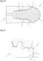
Figuren 10 und 11 ist ein nicht erfindungsgemäßes Ausführungsbeispiel gezeigt, bei dem sich die Durchmesser der konischen ersten Anlagefläche 6 des Einschraubwerkzeugs 1 und der dazugehörigen konischen ersten Auflagefläche 7 der Werkzeugaufnahme 2 in Einschraubrichtung des Einschraubwerkzeugs 1 erweitern. Die erste Anlagefläche 6 und die entsprechende erste Auflagefläche 7 sind um jeweils 5° bezüglich einer zu den Mittelachsen 15 bzw. 18 senkrechten Ebene in Richtung des Werkzeugschafts 4 geneigt. Dadurch weist die erste konische Anlagefläche 6 und auch die erste konische Auflagefläche 7 genau wie in dem Ausführungsbeispiel ausFig. 4 einen Kegelwinkel von 170° auf. Die zweite konische Anlagefläche 8 und die zweite konische Auflagefläche 9 verjüngen sich mit einem Winkel von 5° gegenüber den Mittelachsen 15 und 18, so dass sich ein Kegelwinkel von 10° ergibt. Im Unterschied zu den Ausführungen derFiguren 1 bis 9 zeigen die Kegel, welche den beiden den Doppelkonus bildenden Kegelflächen zugrunde liegen, in entgegen gesetzte Richtungen. - In der
Figur 12 ist ein Ausführungsbeispiel gezeigt, bei dem eine Einsatzbuchse 25, welche die zweite konische Auflagefläche 9, das Innengewinde 17 und die zylindrische Anlagefläche 24 enthält, in die Aufnahmeöffnung 16 der Werkzeugaufnahme 2 eingesetzt ist. Die radialen Bohrungen 20 gehen durch die Werkzeugaufnahme 2 und die Einsatzbuchse 25 und münden in der Aufnahmeöffnung 16 der Werkzeugaufnahme 2. -
Figur 13 zeigt eine vergrößerte Darstellung der Hülse 22 für die äußere Kühlmittelzuführung. In Richtung des Werkzeugs weist die Hülse 22 einen oder mehrere Auslässe 26 auf, durch die das über die radialen Bohrungen 20 nach außen geführte und durch die äußeren Öffnungen 23 austretende Kühlmittel an das Werkzeug bzw. die zu bearbeitende Stelle geleitet werden kann. Der oder die Auslässe 26 können als umlaufender Spalt, Bohrungen Schlitze oder dgl. ausgebildet sein.
Claims (17)
- Einschraubwerkzeug (1), das einen Werkzeugkopf (3) und einen Werkzeugschaft (4) mit einem Außengewinde (5) und einem zwischen dem Werkzeugkopf (3) und dem Außengewinde (5) angeordneten Abstützbereich enthält, dadurch gekennzeichnet, dass der Abstützbereich durch eine an den Werkzeugkopf (3) angrenzende erste konische Anlagefläche (6) mit einem Kegelwinkel von 140° bis 179° und eine zweite konische Anlagefläche (8) mit einem Kegelwinkel von 1° bis 90° gebildet wird, wobei die den konischen Anlageflächen (6, 8) zugrunde liegenden Kegel in dieselbe Richtung zeigen.
- Einschraubwerkzeug (1) nach Anspruch 1, dadurch gekennzeichnet, dass sich die zweite konische Anlagefläche (8) an die erste konische Anlagefläche (6) anschließt.
- Einschraubwerkzeug (1) nach Anspruch 1 oder 2, dadurch gekennzeichnet, dass die erste konische Anlagefläche (6) einen Kegelwinkel von 170° und die zweite konische Anlagefläche einen Kegelwinkel von 10° aufweist.
- Einschraubwerkzeug (1) nach einem der Ansprüche 1 bis 3, dadurch gekennzeichnet, dass am Werkzeugschaft (4) ein weiterer Abstützbereich (11) vorgesehen ist.
- Einschraubwerkzeug (1) nach Anspruch 4, dadurch gekennzeichnet, dass der weitere Abstützbereich (11) kugelförmig, zylindrisch oder konisch ausgebildet ist.
- Einschraubwerkzeug (1) nach einem der Ansprüche 1 bis 5, dadurch gekennzeichnet, dass das Außengewinde (5) eine zum freien Ende (10) des Werkzeugschafts (4) hin abnehmende Gewindetiefe enthält.
- Einschraubwerkzeug (1) nach einem der Ansprüche 1 bis 6, dadurch gekennzeichnet, dass das Außengewinde (5) als Trapez-, Rund-, Flach- oder Spitzgewinde ausgebildet ist.
- Einschraubwerkzeug (1) nach einem der Ansprüche 1 bis 7, dadurch gekennzeichnet, dass am Werkzeugschaft (4) eine Greiferrille (13) zum Einspannen des Einschraubwerkzeugs (1) vorgesehen ist.
- Werkzeugaufnahme (2) für ein Einschraubwerkzeug (1), die eine Aufnahmeöffnung (16) mit einem Innengewinde (17) und einen zwischen einer vorderen Stirnseite der Werkzeugaufnahme (2) und dem Innengewinde (17) angeordneten Abstützbereich enthält, der durch eine an der vorderen Stirnseite der Werkzeugaufnahme (2) angrenzende erste konische Auflagefläche (7) mit einem Kegelwinkel von 140° bis 179° und eine zweite konische Auflagefläche (9) mit einem Kegelwinkel von 1° bis 90° gebildet wird, wobei die den konischen Auflageflächen (7, 9) zugrunde liegenden Kegel in dieselbe Richtung zeigen, dadurch gekennzeichnet, dass in Einschraubrichtung des Einschraubwerkzeugs (1) nach dem Innengewinde (17) an einem inneren Ende der Aufnahmeöffnung (16) ein als zylindrische, kugelförmige oder konische Anlagefläche (24) ausgebildeter innerer Anlagebereich vorgesehen ist.
- Werkzeugaufnahme (2) nach Anspruch 9, dadurch gekennzeichnet, dass sich die zweite konische Auflagefläche (9) an die erste konische Auflagefläche (7) anschließt.
- Werkzeugaufnahme (2) nach Anspruch 10, dadurch gekennzeichnet, dass die erste konische Auflagefläche (7) einen Kegelwinkel von 170° und die zweite konische Auflagefläche (9) einen Kegelwinkel von 10° aufweist.
- Werkzeugaufnahme (2) nach einem der Ansprüche 9 bis 11, dadurch gekennzeichnet, dass das Innengewinde (17) eine zu dem inneren Ende der Aufnahmeöffnung (16) hin abnehmende Gewindetiefe enthält.
- Werkzeugaufnahme (2) nach einem der Ansprüche 9 bis 12, dadurch gekennzeichnet, dass das Innengewinde (17) als Trapez-, Rund-, Flach- oder Spitzgewinde ausgebildet ist.
- Werkzeugaufnahme (2) nach einem der Ansprüche 9 bis 13, dadurch gekennzeichnet, dass sie eine Einsatzbuchse (25) zur Aufnahme des Einschraubwerkzeugs (1) enthält.
- Werkzeugaufnahme (2) nach einem der Ansprüche 9 bis 14, dadurch gekennzeichnet, dass an ihrer Außenseite eine Hülse (22) zur Umlenkung einer über radiale Bohrungen (20) nach außen geführten Kühlflüssigkeit über mindestens eine Öffnung (26) in Richtung des Einschraubwerkzeugs (1) angeordnet ist.
- Werkzeuganordnung mit einem Einschraubwerkzeug (1) und einer Werkzeugaufnahme (2), dadurch gekennzeichnet, dass das Einschraubwerkzeug (1) nach einem der Ansprüche 1 bis 8 und/oder die Werkzeugaufnahme (2) nach einem der Ansprüche 9 bis 15 ausgebildet ist.
- Werkzeuganordnung nach Anspruch 16, dadurch gekennzeichnet, dass der zweite Abstützbereich (11) des Einschraubwerkzeugs (1) ein Übermaß gegenüber der Anlagefläche (24) der Werkzeugaufnahme (2) aufweist und es somit bei der Montage von Einschraubwerkzeug (1) und Werkzeugaufnahme (2) zu einer Pressung zwischen Einschraubwerkzeug (1) und Werkzeugaufnahme (2) kommt.
Priority Applications (1)
| Application Number | Priority Date | Filing Date | Title |
|---|---|---|---|
| EP23185867.1A EP4234140A3 (de) | 2012-02-07 | 2013-01-23 | Einschraubwerkzeug und werkzeugaufnahme für ein derartiges einschraubwerkzeug |
Applications Claiming Priority (2)
| Application Number | Priority Date | Filing Date | Title |
|---|---|---|---|
| DE102012100976.7A DE102012100976B4 (de) | 2012-02-07 | 2012-02-07 | Einschraubwerkzeug und Werkzeugaufnahme für ein derartiges Einschraubwerkzeug |
| PCT/EP2013/051243 WO2013117431A1 (de) | 2012-02-07 | 2013-01-23 | Einschraubwerkzeug und werkzeugaufnahme für ein derartiges einschraubwerkzeug |
Related Child Applications (1)
| Application Number | Title | Priority Date | Filing Date |
|---|---|---|---|
| EP23185867.1A Division EP4234140A3 (de) | 2012-02-07 | 2013-01-23 | Einschraubwerkzeug und werkzeugaufnahme für ein derartiges einschraubwerkzeug |
Publications (2)
| Publication Number | Publication Date |
|---|---|
| EP2812142A1 EP2812142A1 (de) | 2014-12-17 |
| EP2812142B1 true EP2812142B1 (de) | 2023-07-26 |
Family
ID=47633021
Family Applications (2)
| Application Number | Title | Priority Date | Filing Date |
|---|---|---|---|
| EP13702395.8A Active EP2812142B1 (de) | 2012-02-07 | 2013-01-23 | Einschraubwerkzeug und werkzeugaufnahme für ein derartiges einschraubwerkzeug |
| EP23185867.1A Pending EP4234140A3 (de) | 2012-02-07 | 2013-01-23 | Einschraubwerkzeug und werkzeugaufnahme für ein derartiges einschraubwerkzeug |
Family Applications After (1)
| Application Number | Title | Priority Date | Filing Date |
|---|---|---|---|
| EP23185867.1A Pending EP4234140A3 (de) | 2012-02-07 | 2013-01-23 | Einschraubwerkzeug und werkzeugaufnahme für ein derartiges einschraubwerkzeug |
Country Status (16)
| Country | Link |
|---|---|
| US (1) | US9901989B2 (de) |
| EP (2) | EP2812142B1 (de) |
| JP (2) | JP6518065B2 (de) |
| KR (2) | KR20140127844A (de) |
| CN (1) | CN104093513B (de) |
| BR (1) | BR112014019285B8 (de) |
| CA (1) | CA2863269C (de) |
| DE (1) | DE102012100976B4 (de) |
| ES (1) | ES2959388T3 (de) |
| MX (1) | MX357143B (de) |
| MY (1) | MY171823A (de) |
| PL (1) | PL2812142T3 (de) |
| PT (1) | PT2812142T (de) |
| RU (1) | RU2620426C2 (de) |
| SG (1) | SG11201404550TA (de) |
| WO (1) | WO2013117431A1 (de) |
Families Citing this family (31)
| Publication number | Priority date | Publication date | Assignee | Title |
|---|---|---|---|---|
| US9827620B2 (en) * | 2010-09-29 | 2017-11-28 | Mitsubishi Materials Corporation | Head replacement-type cutting tool |
| DE102012100976B4 (de) * | 2012-02-07 | 2014-04-24 | Franz Haimer Maschinenbau Kg | Einschraubwerkzeug und Werkzeugaufnahme für ein derartiges Einschraubwerkzeug |
| DE102013100939A1 (de) * | 2013-01-30 | 2014-07-31 | Franz Haimer Maschinenbau Kg | Werkzeugaufnahme für ein Einschraubwerkzeug |
| US9643262B2 (en) | 2013-07-25 | 2017-05-09 | Kennametal Inc. | Coupling mechanism for cutting tool |
| US9643264B2 (en) | 2013-07-25 | 2017-05-09 | Kennametal Inc. | Coupling mechanism for cutting tool |
| DE202013008019U1 (de) | 2013-09-09 | 2013-09-26 | Peter Langbein | Dämpfungselemente für Werkzeugspannsysteme |
| KR102257817B1 (ko) * | 2014-04-11 | 2021-05-28 | 삼성전자 주식회사 | 전자장치에서 숫자의 입력을 제어하는 방법 및 장치 |
| US9889509B2 (en) | 2014-05-05 | 2018-02-13 | Kennametal Inc. | Cutter heads with improved coupling |
| DE102014214110A1 (de) * | 2014-07-21 | 2016-01-21 | Robert Bosch Gmbh | Hochdruckanschlussvorrichtung |
| CN104759649B (zh) * | 2015-04-28 | 2017-05-24 | 长沙矿山研究院有限责任公司 | 一种动力头钻杆锁紧机构 |
| TWI574762B (zh) * | 2015-05-20 | 2017-03-21 | Hsin Tien Chang | Tool connection of the thread structure |
| WO2016199935A1 (ja) * | 2015-06-12 | 2016-12-15 | 三菱マテリアル株式会社 | テーパエンドミルおよび切削ヘッド |
| DE102015112079A1 (de) | 2015-07-24 | 2017-01-26 | Franz Haimer Maschinenbau Kg | Einschraubwerkzeug und Werkzeugaufnahme mit unterteiltem Stützbereich |
| DE102015112080A1 (de) | 2015-07-24 | 2017-01-26 | Franz Haimer Maschinenbau Kg | Werkzeugaufnahme und Einschraubwerkzeug mit Dichtung |
| DE102015214432A1 (de) * | 2015-07-29 | 2017-02-02 | Franz Haimer Maschinenbau Kg | Rotierbares Zerspan-Werkzeug mit Axialsicherung für Schlüssel sowie Schlüssel |
| DE102015214434A1 (de) * | 2015-07-29 | 2017-02-02 | Franz Haimer Maschinenbau Kg | Rotierbares Zerspan-Werkzeug und Schlüssel hierfür |
| AT15013U1 (de) * | 2015-08-05 | 2016-11-15 | Ceratizit Austria Gmbh | Auswechselbarer Schneidkopf, Werkzeugschaft und Schaftwerkzeug |
| DE102015010399A1 (de) | 2015-08-11 | 2017-03-02 | Iscar Ltd. | Austauschbarer Schneidkopf, der einen Gewindeanbauabschnitt mit zwei beabstandeten konischen Anlageflächen hat, die mit dem gleichen Konuswinkel versehen sind, Werkzeughalter und rotierendes Schneidwerkzeug |
| US9844817B2 (en) | 2015-08-11 | 2017-12-19 | Iscar, Ltd. | Replaceable cutting head having threaded mounting portion with two spaced apart conical abutment surfaces provided with the same cone angle, tool holder and rotary cutting tool |
| DE102015116624B4 (de) | 2015-09-30 | 2023-06-15 | Haimer Gmbh | Schaftfräser |
| DE102015116623A1 (de) | 2015-09-30 | 2017-03-30 | Haimer Gmbh | Schaftfräser |
| US10105771B2 (en) * | 2016-03-21 | 2018-10-23 | Iscar, Ltd. | Rotary cutting tool having tool holder with conical internal thread and replaceable cutting head with straight external thread, and said tool holder |
| US10335871B2 (en) | 2016-04-12 | 2019-07-02 | Iscar, Ltd. | Replaceable face-milling head with integrally formed threaded shank-connector |
| DE102016113373A1 (de) | 2016-07-20 | 2018-01-25 | Franz Haimer Maschinenbau Kg | Werkzeugsystem und Verbindungselement |
| DE102017121363A1 (de) | 2017-09-14 | 2019-03-14 | Franz Haimer Maschinenbau Kg | Gewindeeinsatz zur Befestigung eines Werkzeugs in einer Werkzeugaufnahme und Werkzeugaufnahme mit einem derartigen Gewindeeinsatz |
| JP7041486B2 (ja) * | 2017-10-12 | 2022-03-24 | 三菱鉛筆株式会社 | 筆記具 |
| JP7253649B2 (ja) * | 2017-10-12 | 2023-04-06 | 三菱鉛筆株式会社 | 筆記具 |
| US11446746B2 (en) | 2019-12-10 | 2022-09-20 | Iscar, Ltd. | Replaceable cutting head having back-tapered conical external thread and rotary cutting tool |
| US11376676B2 (en) | 2020-07-07 | 2022-07-05 | Iscar, Ltd. | Rotary cutting head having cutting edges extending past key actuating portion |
| US11426803B2 (en) | 2020-09-08 | 2022-08-30 | Iscar, Ltd. | Replaceable cutting head having external thread with concavely curved root and rotary cutting tool |
| DE102023132906A1 (de) * | 2023-11-24 | 2025-05-28 | Haimer Gmbh | Schaftfräser |
Citations (2)
| Publication number | Priority date | Publication date | Assignee | Title |
|---|---|---|---|---|
| JPH05318208A (ja) * | 1992-05-16 | 1993-12-03 | Ngk Spark Plug Co Ltd | 回転切削工具 |
| US20060051167A1 (en) * | 2004-09-07 | 2006-03-09 | Kennametal Inc. | Toolholder and cutting insert for a toolholder assembly |
Family Cites Families (41)
| Publication number | Priority date | Publication date | Assignee | Title |
|---|---|---|---|---|
| US1569862A (en) | 1924-03-11 | 1926-01-19 | Francis J Lapointe | Broaching machine |
| US1749633A (en) | 1928-01-27 | 1930-03-04 | Lapointe Machine Tool Co | Machine for broaching spirals |
| US2060889A (en) | 1933-07-10 | 1936-11-17 | Colonial Broach Co | Broach |
| US2079692A (en) * | 1933-10-16 | 1937-05-11 | Francis J Lapointe | Broach shank connecter |
| FR1019411A (fr) * | 1950-06-02 | 1953-01-21 | Deragne Freres | Perfectionnement aux réaléseuses portatives |
| US2669468A (en) * | 1950-12-05 | 1954-02-16 | John W Clerke | Threaded joint and element thereof having improved thread form |
| GB848563A (en) * | 1956-06-09 | 1960-09-21 | Birmingham Small Arms Co Ltd | Improvements in or relating to chucks |
| US3087360A (en) * | 1960-07-19 | 1963-04-30 | Waldo L Garberding | Cutting tool having universal joint |
| US4192533A (en) * | 1976-04-22 | 1980-03-11 | Hydril Company | Dovetail connection for pin and box joints |
| SU1349887A1 (ru) * | 1985-05-22 | 1987-11-07 | Московский станкостроительный завод "Красный пролетарий" им.А.И.Ефремова | Наборный режущий инструмент |
| FR2602162B1 (fr) | 1986-08-01 | 1990-03-23 | Begue Pierre | Systeme de fixation d'un outil sur un organe porte-outil de machine-outil, parties constitutives |
| DD275638A1 (de) * | 1988-09-21 | 1990-01-31 | Schmalkalden Werkzeug | Spanneinrichtung fuer auswechselbare werkzeugkoepfe |
| EP0504100B1 (de) * | 1991-03-13 | 1996-04-10 | Polytool Ag | Reibahle mit auswechselbarem Schneidkopf |
| SE509218C2 (sv) * | 1994-08-29 | 1998-12-21 | Sandvik Ab | Skaftverktyg |
| US5873687A (en) * | 1997-04-16 | 1999-02-23 | Mori Seiki Co., Ltd. | Tool unit with hydraulic feed passage |
| DE10009721A1 (de) * | 2000-03-01 | 2001-09-06 | Komet Stahlhalter Werkzeuge | Maschinenreibahle und Reibkopf für eine Maschinenreibahle |
| IL136032A (en) * | 2000-05-09 | 2003-12-10 | Iscar Ltd | Tool joint |
| IL137316A (en) * | 2000-07-16 | 2004-01-04 | Iscar Ltd | Cutting Tools |
| US6565291B2 (en) * | 2000-08-18 | 2003-05-20 | Iscar, Ltd. | Cutting tool assembly |
| JP4610129B2 (ja) * | 2001-06-27 | 2011-01-12 | 京セラ株式会社 | ボールエンドミル |
| JP4378931B2 (ja) * | 2002-03-04 | 2009-12-09 | 三菱マテリアル株式会社 | 刃部交換式切削工具及びこれに装着される刃部 |
| IL150013A (en) * | 2002-06-04 | 2007-06-17 | Gil Hecht | Rotary cutting tool |
| SE526762C2 (sv) * | 2002-06-17 | 2005-11-01 | Sandvik Intellectual Property | Han/hon-koppling uppvisande presspassning mellan delarna |
| SE528251C2 (sv) | 2004-09-24 | 2006-10-03 | Seco Tools Ab | Handel för verktyg samt verktyg med ett övergångsparti mellan ett gängat parti och ett stödjande parti |
| SE528299C2 (sv) | 2004-09-24 | 2006-10-17 | Seco Tools Ab | Skärspets och skärverktyg med hållardel utformad som stympad konisk gänga |
| JP2006150509A (ja) * | 2004-11-30 | 2006-06-15 | Osg Corp | 切削工具 |
| US7694835B1 (en) * | 2005-01-04 | 2010-04-13 | Rexam Closures And Containers Inc. | Drafted neck finish having angled thread face and closure package |
| DE102005012025A1 (de) | 2005-03-16 | 2006-12-07 | Heule, Ulf | Werkzeuganordnung mit männlichen und weiblichen Kupplungselementen |
| TW200724269A (en) | 2005-11-06 | 2007-07-01 | Iscar Ltd | Rotary cutting tool |
| SE530043C2 (sv) * | 2006-04-20 | 2008-02-12 | Sandvik Intellectual Property | Verktyg för spånavskiljande bearbetning samt del därtill |
| JP2008168386A (ja) * | 2007-01-11 | 2008-07-24 | Asahi Diamond Industrial Co Ltd | 回転工具 |
| DE102007012487B4 (de) * | 2007-03-15 | 2016-12-15 | Franz Haimer Maschinenbau Kg | Werkzeughalter |
| SE532394C2 (sv) * | 2007-06-04 | 2010-01-12 | Sandvik Intellectual Property | Verktyg för spånavskiljande bearbetning samt grundkropp härför |
| JP5230653B2 (ja) * | 2007-12-27 | 2013-07-10 | オーエスジー株式会社 | 超硬回転工具、及び超硬回転工具の製造方法 |
| DE102009042395A1 (de) * | 2009-09-16 | 2011-03-24 | Hartmetall-Werkzeugfabrik Paul Horn Gmbh | Reibwerkzeug zur spanenden Bearbeitung eines Werkstücks |
| DE102009048010B3 (de) | 2009-10-02 | 2011-02-17 | Kennametal Inc. | Werkzeuginterface |
| DE102010028561A1 (de) * | 2010-05-04 | 2011-11-10 | Helmut Diebold Gmbh & Co. Goldring-Werkzeugfabrik | Werkzeugaufnahme |
| US9827620B2 (en) | 2010-09-29 | 2017-11-28 | Mitsubishi Materials Corporation | Head replacement-type cutting tool |
| DE102011010897B4 (de) | 2011-02-10 | 2023-02-09 | Gebr. Brasseler Gmbh & Co. Kg | Dentalinstrument sowie Verfahren zu dessen Herstellung |
| AT13405U1 (de) | 2012-01-20 | 2013-12-15 | Ceratizit Austria Gmbh | Hartwerkstoff-gewindeverbindung |
| DE102012100976B4 (de) * | 2012-02-07 | 2014-04-24 | Franz Haimer Maschinenbau Kg | Einschraubwerkzeug und Werkzeugaufnahme für ein derartiges Einschraubwerkzeug |
-
2012
- 2012-02-07 DE DE102012100976.7A patent/DE102012100976B4/de not_active Revoked
-
2013
- 2013-01-23 KR KR1020147024577A patent/KR20140127844A/ko not_active Ceased
- 2013-01-23 PT PT137023958T patent/PT2812142T/pt unknown
- 2013-01-23 CN CN201380007901.7A patent/CN104093513B/zh active Active
- 2013-01-23 BR BR112014019285A patent/BR112014019285B8/pt active IP Right Grant
- 2013-01-23 MX MX2014009467A patent/MX357143B/es active IP Right Grant
- 2013-01-23 PL PL13702395.8T patent/PL2812142T3/pl unknown
- 2013-01-23 ES ES13702395T patent/ES2959388T3/es active Active
- 2013-01-23 SG SG11201404550TA patent/SG11201404550TA/en unknown
- 2013-01-23 JP JP2014555993A patent/JP6518065B2/ja active Active
- 2013-01-23 CA CA2863269A patent/CA2863269C/en active Active
- 2013-01-23 EP EP13702395.8A patent/EP2812142B1/de active Active
- 2013-01-23 RU RU2014133094A patent/RU2620426C2/ru active
- 2013-01-23 MY MYPI2014702159A patent/MY171823A/en unknown
- 2013-01-23 WO PCT/EP2013/051243 patent/WO2013117431A1/de not_active Ceased
- 2013-01-23 EP EP23185867.1A patent/EP4234140A3/de active Pending
- 2013-01-23 US US14/376,738 patent/US9901989B2/en active Active
- 2013-01-23 KR KR1020167034106A patent/KR101965173B1/ko active Active
-
2016
- 2016-12-27 JP JP2016252366A patent/JP6798875B2/ja active Active
Patent Citations (2)
| Publication number | Priority date | Publication date | Assignee | Title |
|---|---|---|---|---|
| JPH05318208A (ja) * | 1992-05-16 | 1993-12-03 | Ngk Spark Plug Co Ltd | 回転切削工具 |
| US20060051167A1 (en) * | 2004-09-07 | 2006-03-09 | Kennametal Inc. | Toolholder and cutting insert for a toolholder assembly |
Also Published As
| Publication number | Publication date |
|---|---|
| JP6518065B2 (ja) | 2019-05-22 |
| DE102012100976B4 (de) | 2014-04-24 |
| PT2812142T (pt) | 2023-10-04 |
| CA2863269C (en) | 2017-09-12 |
| EP2812142A1 (de) | 2014-12-17 |
| RU2014133094A (ru) | 2016-03-27 |
| JP6798875B2 (ja) | 2020-12-09 |
| MX357143B (es) | 2018-06-28 |
| US9901989B2 (en) | 2018-02-27 |
| JP2017104976A (ja) | 2017-06-15 |
| BR112014019285A2 (de) | 2017-06-20 |
| KR20140127844A (ko) | 2014-11-04 |
| CN104093513A (zh) | 2014-10-08 |
| US20150016905A1 (en) | 2015-01-15 |
| EP4234140A3 (de) | 2023-11-01 |
| PL2812142T3 (pl) | 2024-03-04 |
| KR20160148031A (ko) | 2016-12-23 |
| WO2013117431A1 (de) | 2013-08-15 |
| ES2959388T3 (es) | 2024-02-26 |
| BR112014019285B8 (pt) | 2022-11-22 |
| MY171823A (en) | 2019-10-31 |
| BR112014019285B1 (pt) | 2022-02-15 |
| CA2863269A1 (en) | 2013-08-15 |
| DE102012100976A1 (de) | 2013-08-08 |
| JP2015509854A (ja) | 2015-04-02 |
| EP4234140A2 (de) | 2023-08-30 |
| CN104093513B (zh) | 2018-01-26 |
| BR112014019285A8 (pt) | 2017-07-11 |
| SG11201404550TA (en) | 2014-11-27 |
| MX2014009467A (es) | 2015-03-19 |
| KR101965173B1 (ko) | 2019-04-03 |
| RU2620426C2 (ru) | 2017-05-25 |
Similar Documents
| Publication | Publication Date | Title |
|---|---|---|
| EP2812142B1 (de) | Einschraubwerkzeug und werkzeugaufnahme für ein derartiges einschraubwerkzeug | |
| EP2950955B1 (de) | Werkzeugaufnahme für ein werkzeug mit einem mit einem aussengewinde versehenen werkzeugschaft | |
| EP1265723B1 (de) | Maschinenreibahle und reibkopf für eine maschinenreibahle | |
| EP2885094B1 (de) | Werkzeuganordnung | |
| DE3108439C1 (de) | Bohrwerkzeug, insbesondere Bohrstange | |
| DE102007012487B4 (de) | Werkzeughalter | |
| EP2855058B1 (de) | Werkzeugaufnahme für ein einschraubwerkzeug | |
| DE102010004526B4 (de) | Zerspanungswerkzeug | |
| EP2266732B1 (de) | Spannsystem | |
| DE3912503A1 (de) | Spanneinrichtung fuer auswechselbare werkzeugkoepfe | |
| EP0523404A1 (de) | Zweischneidiges Gesenkwerkzeug zum Fräsen und Bohren | |
| DE102015119060B3 (de) | Spannvorrichtung | |
| EP3016770B1 (de) | Wechselkopfsystem für die metallbearbeitung | |
| DE10222048A1 (de) | Werkzeug und Verfahren zur Maschinenbearbeitung von Werkstücken | |
| DE19831743B4 (de) | Vorrichtung zum Bearbeiten von Werkstücken | |
| DE3237128A1 (de) | Kombinationswerkzeug | |
| DE202017107139U1 (de) | Werkzeug zur spanenden Bearbeitung eines Werkstücks | |
| DE20105764U1 (de) | Vorrichtung zum Bearbeiten von Werkstücken | |
| DE202007014828U1 (de) | Spannfutter für zu spannende Teile | |
| EP3043938B1 (de) | Schneidwerkzeug | |
| EP1316375B1 (de) | Vorrichtung zur Aufnahme von Werkzeugen | |
| DE102016113373A1 (de) | Werkzeugsystem und Verbindungselement | |
| DE3700841A1 (de) | Kupplungselement, insbesondere zum kraft- und formschluessigen verbinden eines werkzeugkopfes mit einem werkzeugtraeger | |
| DE102022107025A1 (de) | Werkzeughalter | |
| DE102023115910A1 (de) | Reibwerkzeug |
Legal Events
| Date | Code | Title | Description |
|---|---|---|---|
| PUAI | Public reference made under article 153(3) epc to a published international application that has entered the european phase |
Free format text: ORIGINAL CODE: 0009012 |
|
| 17P | Request for examination filed |
Effective date: 20140908 |
|
| AK | Designated contracting states |
Kind code of ref document: A1 Designated state(s): AL AT BE BG CH CY CZ DE DK EE ES FI FR GB GR HR HU IE IS IT LI LT LU LV MC MK MT NL NO PL PT RO RS SE SI SK SM TR |
|
| AX | Request for extension of the european patent |
Extension state: BA ME |
|
| DAX | Request for extension of the european patent (deleted) | ||
| STAA | Information on the status of an ep patent application or granted ep patent |
Free format text: STATUS: EXAMINATION IS IN PROGRESS |
|
| 17Q | First examination report despatched |
Effective date: 20171206 |
|
| RIC1 | Information provided on ipc code assigned before grant |
Ipc: B23C 5/26 19680901ALI20221229BHEP Ipc: B23C 5/10 19680901ALI20221229BHEP Ipc: B23B 31/11 19900101AFI20221229BHEP |
|
| GRAP | Despatch of communication of intention to grant a patent |
Free format text: ORIGINAL CODE: EPIDOSNIGR1 |
|
| STAA | Information on the status of an ep patent application or granted ep patent |
Free format text: STATUS: GRANT OF PATENT IS INTENDED |
|
| INTG | Intention to grant announced |
Effective date: 20230322 |
|
| GRAS | Grant fee paid |
Free format text: ORIGINAL CODE: EPIDOSNIGR3 |
|
| GRAA | (expected) grant |
Free format text: ORIGINAL CODE: 0009210 |
|
| STAA | Information on the status of an ep patent application or granted ep patent |
Free format text: STATUS: THE PATENT HAS BEEN GRANTED |
|
| AK | Designated contracting states |
Kind code of ref document: B1 Designated state(s): AL AT BE BG CH CY CZ DE DK EE ES FI FR GB GR HR HU IE IS IT LI LT LU LV MC MK MT NL NO PL PT RO RS SE SI SK SM TR |
|
| REG | Reference to a national code |
Ref country code: CH Ref legal event code: EP |
|
| REG | Reference to a national code |
Ref country code: IE Ref legal event code: FG4D Free format text: LANGUAGE OF EP DOCUMENT: GERMAN |
|
| REG | Reference to a national code |
Ref country code: DE Ref legal event code: R096 Ref document number: 502013016432 Country of ref document: DE |
|
| REG | Reference to a national code |
Ref country code: PT Ref legal event code: SC4A Ref document number: 2812142 Country of ref document: PT Date of ref document: 20231004 Kind code of ref document: T Free format text: AVAILABILITY OF NATIONAL TRANSLATION Effective date: 20230927 |
|
| REG | Reference to a national code |
Ref country code: SE Ref legal event code: TRGR |
|
| REG | Reference to a national code |
Ref country code: LT Ref legal event code: MG9D |
|
| REG | Reference to a national code |
Ref country code: NL Ref legal event code: MP Effective date: 20230726 |
|
| P01 | Opt-out of the competence of the unified patent court (upc) registered |
Effective date: 20231106 |
|
| PG25 | Lapsed in a contracting state [announced via postgrant information from national office to epo] |
Ref country code: NL Free format text: LAPSE BECAUSE OF FAILURE TO SUBMIT A TRANSLATION OF THE DESCRIPTION OR TO PAY THE FEE WITHIN THE PRESCRIBED TIME-LIMIT Effective date: 20230726 |
|
| PG25 | Lapsed in a contracting state [announced via postgrant information from national office to epo] |
Ref country code: GR Free format text: LAPSE BECAUSE OF FAILURE TO SUBMIT A TRANSLATION OF THE DESCRIPTION OR TO PAY THE FEE WITHIN THE PRESCRIBED TIME-LIMIT Effective date: 20231027 |
|
| PG25 | Lapsed in a contracting state [announced via postgrant information from national office to epo] |
Ref country code: IS Free format text: LAPSE BECAUSE OF FAILURE TO SUBMIT A TRANSLATION OF THE DESCRIPTION OR TO PAY THE FEE WITHIN THE PRESCRIBED TIME-LIMIT Effective date: 20231126 |
|
| PG25 | Lapsed in a contracting state [announced via postgrant information from national office to epo] |
Ref country code: RS Free format text: LAPSE BECAUSE OF FAILURE TO SUBMIT A TRANSLATION OF THE DESCRIPTION OR TO PAY THE FEE WITHIN THE PRESCRIBED TIME-LIMIT Effective date: 20230726 Ref country code: NO Free format text: LAPSE BECAUSE OF FAILURE TO SUBMIT A TRANSLATION OF THE DESCRIPTION OR TO PAY THE FEE WITHIN THE PRESCRIBED TIME-LIMIT Effective date: 20231026 Ref country code: LV Free format text: LAPSE BECAUSE OF FAILURE TO SUBMIT A TRANSLATION OF THE DESCRIPTION OR TO PAY THE FEE WITHIN THE PRESCRIBED TIME-LIMIT Effective date: 20230726 Ref country code: LT Free format text: LAPSE BECAUSE OF FAILURE TO SUBMIT A TRANSLATION OF THE DESCRIPTION OR TO PAY THE FEE WITHIN THE PRESCRIBED TIME-LIMIT Effective date: 20230726 Ref country code: IS Free format text: LAPSE BECAUSE OF FAILURE TO SUBMIT A TRANSLATION OF THE DESCRIPTION OR TO PAY THE FEE WITHIN THE PRESCRIBED TIME-LIMIT Effective date: 20231126 Ref country code: HR Free format text: LAPSE BECAUSE OF FAILURE TO SUBMIT A TRANSLATION OF THE DESCRIPTION OR TO PAY THE FEE WITHIN THE PRESCRIBED TIME-LIMIT Effective date: 20230726 Ref country code: GR Free format text: LAPSE BECAUSE OF FAILURE TO SUBMIT A TRANSLATION OF THE DESCRIPTION OR TO PAY THE FEE WITHIN THE PRESCRIBED TIME-LIMIT Effective date: 20231027 Ref country code: FI Free format text: LAPSE BECAUSE OF FAILURE TO SUBMIT A TRANSLATION OF THE DESCRIPTION OR TO PAY THE FEE WITHIN THE PRESCRIBED TIME-LIMIT Effective date: 20230726 |
|
| REG | Reference to a national code |
Ref country code: ES Ref legal event code: FG2A Ref document number: 2959388 Country of ref document: ES Kind code of ref document: T3 Effective date: 20240226 |
|
| REG | Reference to a national code |
Ref country code: DE Ref legal event code: R097 Ref document number: 502013016432 Country of ref document: DE |
|
| PG25 | Lapsed in a contracting state [announced via postgrant information from national office to epo] |
Ref country code: SM Free format text: LAPSE BECAUSE OF FAILURE TO SUBMIT A TRANSLATION OF THE DESCRIPTION OR TO PAY THE FEE WITHIN THE PRESCRIBED TIME-LIMIT Effective date: 20230726 Ref country code: RO Free format text: LAPSE BECAUSE OF FAILURE TO SUBMIT A TRANSLATION OF THE DESCRIPTION OR TO PAY THE FEE WITHIN THE PRESCRIBED TIME-LIMIT Effective date: 20230726 Ref country code: EE Free format text: LAPSE BECAUSE OF FAILURE TO SUBMIT A TRANSLATION OF THE DESCRIPTION OR TO PAY THE FEE WITHIN THE PRESCRIBED TIME-LIMIT Effective date: 20230726 Ref country code: DK Free format text: LAPSE BECAUSE OF FAILURE TO SUBMIT A TRANSLATION OF THE DESCRIPTION OR TO PAY THE FEE WITHIN THE PRESCRIBED TIME-LIMIT Effective date: 20230726 Ref country code: CZ Free format text: LAPSE BECAUSE OF FAILURE TO SUBMIT A TRANSLATION OF THE DESCRIPTION OR TO PAY THE FEE WITHIN THE PRESCRIBED TIME-LIMIT Effective date: 20230726 Ref country code: SK Free format text: LAPSE BECAUSE OF FAILURE TO SUBMIT A TRANSLATION OF THE DESCRIPTION OR TO PAY THE FEE WITHIN THE PRESCRIBED TIME-LIMIT Effective date: 20230726 |
|
| PLBE | No opposition filed within time limit |
Free format text: ORIGINAL CODE: 0009261 |
|
| STAA | Information on the status of an ep patent application or granted ep patent |
Free format text: STATUS: NO OPPOSITION FILED WITHIN TIME LIMIT |
|
| 26N | No opposition filed |
Effective date: 20240429 |
|
| PG25 | Lapsed in a contracting state [announced via postgrant information from national office to epo] |
Ref country code: SI Free format text: LAPSE BECAUSE OF FAILURE TO SUBMIT A TRANSLATION OF THE DESCRIPTION OR TO PAY THE FEE WITHIN THE PRESCRIBED TIME-LIMIT Effective date: 20230726 |
|
| PG25 | Lapsed in a contracting state [announced via postgrant information from national office to epo] |
Ref country code: MC Free format text: LAPSE BECAUSE OF FAILURE TO SUBMIT A TRANSLATION OF THE DESCRIPTION OR TO PAY THE FEE WITHIN THE PRESCRIBED TIME-LIMIT Effective date: 20230726 |
|
| PG25 | Lapsed in a contracting state [announced via postgrant information from national office to epo] |
Ref country code: MC Free format text: LAPSE BECAUSE OF FAILURE TO SUBMIT A TRANSLATION OF THE DESCRIPTION OR TO PAY THE FEE WITHIN THE PRESCRIBED TIME-LIMIT Effective date: 20230726 |
|
| PG25 | Lapsed in a contracting state [announced via postgrant information from national office to epo] |
Ref country code: LU Free format text: LAPSE BECAUSE OF NON-PAYMENT OF DUE FEES Effective date: 20240123 |
|
| PG25 | Lapsed in a contracting state [announced via postgrant information from national office to epo] |
Ref country code: LU Free format text: LAPSE BECAUSE OF NON-PAYMENT OF DUE FEES Effective date: 20240123 |
|
| PG25 | Lapsed in a contracting state [announced via postgrant information from national office to epo] |
Ref country code: BE Free format text: LAPSE BECAUSE OF NON-PAYMENT OF DUE FEES Effective date: 20240131 |
|
| PG25 | Lapsed in a contracting state [announced via postgrant information from national office to epo] |
Ref country code: BE Free format text: LAPSE BECAUSE OF NON-PAYMENT OF DUE FEES Effective date: 20240131 |
|
| REG | Reference to a national code |
Ref country code: BE Ref legal event code: MM Effective date: 20240131 |
|
| PG25 | Lapsed in a contracting state [announced via postgrant information from national office to epo] |
Ref country code: BG Free format text: LAPSE BECAUSE OF FAILURE TO SUBMIT A TRANSLATION OF THE DESCRIPTION OR TO PAY THE FEE WITHIN THE PRESCRIBED TIME-LIMIT Effective date: 20230726 |
|
| PG25 | Lapsed in a contracting state [announced via postgrant information from national office to epo] |
Ref country code: BG Free format text: LAPSE BECAUSE OF FAILURE TO SUBMIT A TRANSLATION OF THE DESCRIPTION OR TO PAY THE FEE WITHIN THE PRESCRIBED TIME-LIMIT Effective date: 20230726 |
|
| PG25 | Lapsed in a contracting state [announced via postgrant information from national office to epo] |
Ref country code: IE Free format text: LAPSE BECAUSE OF NON-PAYMENT OF DUE FEES Effective date: 20240123 |
|
| PG25 | Lapsed in a contracting state [announced via postgrant information from national office to epo] |
Ref country code: IE Free format text: LAPSE BECAUSE OF NON-PAYMENT OF DUE FEES Effective date: 20240123 |
|
| PGFP | Annual fee paid to national office [announced via postgrant information from national office to epo] |
Ref country code: PT Payment date: 20250114 Year of fee payment: 13 Ref country code: DE Payment date: 20250120 Year of fee payment: 13 |
|
| PGFP | Annual fee paid to national office [announced via postgrant information from national office to epo] |
Ref country code: ES Payment date: 20250214 Year of fee payment: 13 |
|
| PGFP | Annual fee paid to national office [announced via postgrant information from national office to epo] |
Ref country code: SE Payment date: 20250122 Year of fee payment: 13 |
|
| PGFP | Annual fee paid to national office [announced via postgrant information from national office to epo] |
Ref country code: CH Payment date: 20250201 Year of fee payment: 13 Ref country code: AT Payment date: 20250120 Year of fee payment: 13 |
|
| PGFP | Annual fee paid to national office [announced via postgrant information from national office to epo] |
Ref country code: FR Payment date: 20250122 Year of fee payment: 13 Ref country code: PL Payment date: 20250114 Year of fee payment: 13 |
|
| PGFP | Annual fee paid to national office [announced via postgrant information from national office to epo] |
Ref country code: IT Payment date: 20250131 Year of fee payment: 13 Ref country code: GB Payment date: 20250123 Year of fee payment: 13 |
|
| PGFP | Annual fee paid to national office [announced via postgrant information from national office to epo] |
Ref country code: TR Payment date: 20250116 Year of fee payment: 13 |
|
| PG25 | Lapsed in a contracting state [announced via postgrant information from national office to epo] |
Ref country code: CY Free format text: LAPSE BECAUSE OF FAILURE TO SUBMIT A TRANSLATION OF THE DESCRIPTION OR TO PAY THE FEE WITHIN THE PRESCRIBED TIME-LIMIT; INVALID AB INITIO Effective date: 20130123 |
|
| PG25 | Lapsed in a contracting state [announced via postgrant information from national office to epo] |
Ref country code: HU Free format text: LAPSE BECAUSE OF FAILURE TO SUBMIT A TRANSLATION OF THE DESCRIPTION OR TO PAY THE FEE WITHIN THE PRESCRIBED TIME-LIMIT; INVALID AB INITIO Effective date: 20130123 |
|
| REG | Reference to a national code |
Ref country code: CH Ref legal event code: U11 Free format text: ST27 STATUS EVENT CODE: U-0-0-U10-U11 (AS PROVIDED BY THE NATIONAL OFFICE) Effective date: 20260201 |