EP2811129B1 - Abgasreinigungsvorrichtung für einen verbrennungsmotor - Google Patents
Abgasreinigungsvorrichtung für einen verbrennungsmotor Download PDFInfo
- Publication number
- EP2811129B1 EP2811129B1 EP12867208.6A EP12867208A EP2811129B1 EP 2811129 B1 EP2811129 B1 EP 2811129B1 EP 12867208 A EP12867208 A EP 12867208A EP 2811129 B1 EP2811129 B1 EP 2811129B1
- Authority
- EP
- European Patent Office
- Prior art keywords
- temperature
- additive agent
- reducing agent
- exhaust gas
- combustion engine
- Prior art date
- Legal status (The legal status is an assumption and is not a legal conclusion. Google has not performed a legal analysis and makes no representation as to the accuracy of the status listed.)
- Not-in-force
Links
Images


Classifications
-
- F—MECHANICAL ENGINEERING; LIGHTING; HEATING; WEAPONS; BLASTING
- F01—MACHINES OR ENGINES IN GENERAL; ENGINE PLANTS IN GENERAL; STEAM ENGINES
- F01N—GAS-FLOW SILENCERS OR EXHAUST APPARATUS FOR MACHINES OR ENGINES IN GENERAL; GAS-FLOW SILENCERS OR EXHAUST APPARATUS FOR INTERNAL-COMBUSTION ENGINES
- F01N3/00—Exhaust or silencing apparatus having means for purifying, rendering innocuous, or otherwise treating exhaust
- F01N3/08—Exhaust or silencing apparatus having means for purifying, rendering innocuous, or otherwise treating exhaust for rendering innocuous
- F01N3/10—Exhaust or silencing apparatus having means for purifying, rendering innocuous, or otherwise treating exhaust for rendering innocuous by thermal or catalytic conversion of noxious components of exhaust
- F01N3/18—Exhaust or silencing apparatus having means for purifying, rendering innocuous, or otherwise treating exhaust for rendering innocuous by thermal or catalytic conversion of noxious components of exhaust characterised by methods of operation; Control
- F01N3/20—Exhaust or silencing apparatus having means for purifying, rendering innocuous, or otherwise treating exhaust for rendering innocuous by thermal or catalytic conversion of noxious components of exhaust characterised by methods of operation; Control specially adapted for catalytic conversion
- F01N3/206—Adding periodically or continuously substances to exhaust gases for promoting purification, e.g. catalytic material in liquid form, NOx reducing agents
- F01N3/208—Control of selective catalytic reduction [SCR], e.g. by adjusting the dosing of reducing agent
-
- F—MECHANICAL ENGINEERING; LIGHTING; HEATING; WEAPONS; BLASTING
- F01—MACHINES OR ENGINES IN GENERAL; ENGINE PLANTS IN GENERAL; STEAM ENGINES
- F01N—GAS-FLOW SILENCERS OR EXHAUST APPARATUS FOR MACHINES OR ENGINES IN GENERAL; GAS-FLOW SILENCERS OR EXHAUST APPARATUS FOR INTERNAL-COMBUSTION ENGINES
- F01N2610/00—Adding substances to exhaust gases
- F01N2610/02—Adding substances to exhaust gases the substance being ammonia or urea
-
- F—MECHANICAL ENGINEERING; LIGHTING; HEATING; WEAPONS; BLASTING
- F01—MACHINES OR ENGINES IN GENERAL; ENGINE PLANTS IN GENERAL; STEAM ENGINES
- F01N—GAS-FLOW SILENCERS OR EXHAUST APPARATUS FOR MACHINES OR ENGINES IN GENERAL; GAS-FLOW SILENCERS OR EXHAUST APPARATUS FOR INTERNAL-COMBUSTION ENGINES
- F01N2610/00—Adding substances to exhaust gases
- F01N2610/06—Adding substances to exhaust gases the substance being in the gaseous form
-
- F—MECHANICAL ENGINEERING; LIGHTING; HEATING; WEAPONS; BLASTING
- F01—MACHINES OR ENGINES IN GENERAL; ENGINE PLANTS IN GENERAL; STEAM ENGINES
- F01N—GAS-FLOW SILENCERS OR EXHAUST APPARATUS FOR MACHINES OR ENGINES IN GENERAL; GAS-FLOW SILENCERS OR EXHAUST APPARATUS FOR INTERNAL-COMBUSTION ENGINES
- F01N2610/00—Adding substances to exhaust gases
- F01N2610/08—Adding substances to exhaust gases with prior mixing of the substances with a gas, e.g. air
- F01N2610/085—Controlling the air supply
-
- F—MECHANICAL ENGINEERING; LIGHTING; HEATING; WEAPONS; BLASTING
- F01—MACHINES OR ENGINES IN GENERAL; ENGINE PLANTS IN GENERAL; STEAM ENGINES
- F01N—GAS-FLOW SILENCERS OR EXHAUST APPARATUS FOR MACHINES OR ENGINES IN GENERAL; GAS-FLOW SILENCERS OR EXHAUST APPARATUS FOR INTERNAL-COMBUSTION ENGINES
- F01N2610/00—Adding substances to exhaust gases
- F01N2610/10—Adding substances to exhaust gases the substance being heated, e.g. by heating tank or supply line of the added substance
-
- F—MECHANICAL ENGINEERING; LIGHTING; HEATING; WEAPONS; BLASTING
- F01—MACHINES OR ENGINES IN GENERAL; ENGINE PLANTS IN GENERAL; STEAM ENGINES
- F01N—GAS-FLOW SILENCERS OR EXHAUST APPARATUS FOR MACHINES OR ENGINES IN GENERAL; GAS-FLOW SILENCERS OR EXHAUST APPARATUS FOR INTERNAL-COMBUSTION ENGINES
- F01N2610/00—Adding substances to exhaust gases
- F01N2610/10—Adding substances to exhaust gases the substance being heated, e.g. by heating tank or supply line of the added substance
- F01N2610/105—Control thereof
-
- F—MECHANICAL ENGINEERING; LIGHTING; HEATING; WEAPONS; BLASTING
- F01—MACHINES OR ENGINES IN GENERAL; ENGINE PLANTS IN GENERAL; STEAM ENGINES
- F01N—GAS-FLOW SILENCERS OR EXHAUST APPARATUS FOR MACHINES OR ENGINES IN GENERAL; GAS-FLOW SILENCERS OR EXHAUST APPARATUS FOR INTERNAL-COMBUSTION ENGINES
- F01N2610/00—Adding substances to exhaust gases
- F01N2610/12—Adding substances to exhaust gases the substance being in solid form, e.g. pellets or powder
-
- F—MECHANICAL ENGINEERING; LIGHTING; HEATING; WEAPONS; BLASTING
- F01—MACHINES OR ENGINES IN GENERAL; ENGINE PLANTS IN GENERAL; STEAM ENGINES
- F01N—GAS-FLOW SILENCERS OR EXHAUST APPARATUS FOR MACHINES OR ENGINES IN GENERAL; GAS-FLOW SILENCERS OR EXHAUST APPARATUS FOR INTERNAL-COMBUSTION ENGINES
- F01N2900/00—Details of electrical control or of the monitoring of the exhaust gas treating apparatus
- F01N2900/06—Parameters used for exhaust control or diagnosing
- F01N2900/18—Parameters used for exhaust control or diagnosing said parameters being related to the system for adding a substance into the exhaust
- F01N2900/1806—Properties of reducing agent or dosing system
- F01N2900/1808—Pressure
-
- F—MECHANICAL ENGINEERING; LIGHTING; HEATING; WEAPONS; BLASTING
- F01—MACHINES OR ENGINES IN GENERAL; ENGINE PLANTS IN GENERAL; STEAM ENGINES
- F01N—GAS-FLOW SILENCERS OR EXHAUST APPARATUS FOR MACHINES OR ENGINES IN GENERAL; GAS-FLOW SILENCERS OR EXHAUST APPARATUS FOR INTERNAL-COMBUSTION ENGINES
- F01N2900/00—Details of electrical control or of the monitoring of the exhaust gas treating apparatus
- F01N2900/06—Parameters used for exhaust control or diagnosing
- F01N2900/18—Parameters used for exhaust control or diagnosing said parameters being related to the system for adding a substance into the exhaust
- F01N2900/1806—Properties of reducing agent or dosing system
- F01N2900/1811—Temperature
-
- F—MECHANICAL ENGINEERING; LIGHTING; HEATING; WEAPONS; BLASTING
- F01—MACHINES OR ENGINES IN GENERAL; ENGINE PLANTS IN GENERAL; STEAM ENGINES
- F01N—GAS-FLOW SILENCERS OR EXHAUST APPARATUS FOR MACHINES OR ENGINES IN GENERAL; GAS-FLOW SILENCERS OR EXHAUST APPARATUS FOR INTERNAL-COMBUSTION ENGINES
- F01N2900/00—Details of electrical control or of the monitoring of the exhaust gas treating apparatus
- F01N2900/06—Parameters used for exhaust control or diagnosing
- F01N2900/18—Parameters used for exhaust control or diagnosing said parameters being related to the system for adding a substance into the exhaust
- F01N2900/1806—Properties of reducing agent or dosing system
- F01N2900/1824—Properties of the air to be mixed with added substances, e.g. air pressure or air temperature
-
- Y—GENERAL TAGGING OF NEW TECHNOLOGICAL DEVELOPMENTS; GENERAL TAGGING OF CROSS-SECTIONAL TECHNOLOGIES SPANNING OVER SEVERAL SECTIONS OF THE IPC; TECHNICAL SUBJECTS COVERED BY FORMER USPC CROSS-REFERENCE ART COLLECTIONS [XRACs] AND DIGESTS
- Y02—TECHNOLOGIES OR APPLICATIONS FOR MITIGATION OR ADAPTATION AGAINST CLIMATE CHANGE
- Y02T—CLIMATE CHANGE MITIGATION TECHNOLOGIES RELATED TO TRANSPORTATION
- Y02T10/00—Road transport of goods or passengers
- Y02T10/10—Internal combustion engine [ICE] based vehicles
- Y02T10/12—Improving ICE efficiencies
Definitions
- the present invention relates to an exhaust gas purification apparatus for an internal combustion engine.
- the reducing agent of high concentration when supplied into the exhaust gas, the reducing agent is small in volume, and hence, it becomes difficult for the reducing agent to disperse in the exhaust gas. In that case, there will occur a variation in the concentration of the reducing agent in a catalyst, so there will be a fear that the removal or reduction rate of NOx may decrease.
- US 5 884 475 A discloses that nitrogen oxides emitted by an internal-combustion engine operated with excess air are normally converted by the method of selective catalytic reduction by bringing the nitrogen oxides, together with ammonia, into contact with a selective catalyst. Due to the dangers associated with the use of ammonia, in a motor vehicle ammonia should only be carried in the form of a substance which liberates ammonia, generally an aqueous urea solution.
- a method and a device for introducing liquid into an exhaust-gas purification system according to the invention avoids frost damage to sections of the system during shutdown times and permits operation of the system at temperatures below the freezing point of the reducing agent solution being used.
- the method and device include a (thermally insulated) reservoir for the reducing agent liquid and a liquid supply line which is connected thereto and terminates in an outlet opening for the liquid.
- the reservoir and the liquid supply line can be heated.
- a heater is provided for liquefying a starting volume which is small as compared with the volume of the reservoir.
- the liquid supply line may also have a back-flush valve to which a gas that is under pressure can be applied. The supply line can consequently be blown free.
- the present invention has been made in view of the problems as referred to above, and has for its object to supply an additive agent in an appropriate manner.
- an exhaust gas purification apparatus for an internal combustion engine includes an exhaust gas purification catalyst that is arranged in an exhaust passage of the internal combustion engine; a tank that stores an additive agent in a solid or a liquid state, which is supplied to said exhaust gas purification catalyst and which acts as a reducing agent or an oxidizing agent; a vaporization device that vaporizes said solid or liquid additive agent by heating the same; and a supply passage that is connected between said tank and said exhaust passage at the upstream side of said exhaust gas purification catalyst, with a gaseous additive agent vaporized by said vaporization device flowing therethrough, wherein the gaseous additive agent vaporized by said vaporization device is supplied to said exhaust passage at the upstream side of said exhaust gas purification catalyst; said exhaust gas purification apparatus comprising:
- the dilution device dilutes the additive agent by supplying the gas different from the additive agent to the gaseous additive agent.
- the dilution device dilutes the additive agent with the use of an exhaust gas of the internal combustion engine or air, for example.
- the dilution device dilutes the additive agent, before the additive agent is supplied from the supply passage to the exhaust passage.
- concentration of the additive agent is decreased, so the adjustment of the amount of supply of the additive agent to be supplied becomes easy. That is, the additive agent is diluted at the upstream side of an adjusting device, and hence, the volume of the additive agent adjusted in the metering device becomes relatively large, thus making it possible to enhance accuracy in adjusting the amount of supply of the additive agent.
- the volume of the additive agent becomes large, it becomes easy for the additive agent to disperse into the exhaust gas after being supplied to the exhaust passage.
- an adjusting device is arranged in said supply passage at the upstream side of said metering device, for adjusting the temperature or pressure of the additive agent which has been diluted by said dilution device.
- the adjusting device may adjust the temperature or pressure of the gaseous additive agent before diluted, or the temperature or pressure of a gas (hereinafter also referred to as a dilution gas) which is supplied by the dilution device. That is, the temperature or pressure of the additive agent after diluted may be adjusted by adjusting the temperature or pressure of the additive agent or the dilution gas before diluted.
- a gas hereinafter also referred to as a dilution gas
- the additive agent may condense.
- the temperature or pressure of the additive agent is adjusted by the adjusting device, so it is possible to suppress the additive agent from condensing. For example, by making high the temperature of the additive agent after diluted, the condensation of the additive agent can be suppressed. In addition, even if the additive agent condenses, an amount of condensation thereof, which becomes liquid, can be made small. As a result of this, the additive agent can be dispersed over a wide range in the exhaust gas.
- the temperature of the additive agent may be raised by causing the pressure of the additive agent to go up. That is, because the temperature and the pressure thereof are correlated with each other, the adjusting device need only adjust at least either one of the temperature and the pressure.
- said adjusting device can adjust the temperature or pressure of said additive agent so that the temperature of the additive agent after being diluted by said dilution device becomes higher than a dew point temperature thereof.
- the temperature of the additive agent after diluted is higher than the dew point temperature thereof, it is possible to suppress the additive agent from condensing in a more reliable manner.
- said adjusting device may adjust the temperature of the additive agent after being diluted by said dilution device, and said adjusting device may also make the pressure of the additive agent to be supplied from said supply passage to the exhaust passage lower in cases where the amount of heat required to make the temperature of the additive agent after being diluted by said dilution device higher than the dew point temperature thereof is equal to or greater than a threshold value, than in cases where it is less than the threshold value.
- heating the additive agent results in a deterioration of fuel economy.
- the temperature of an engine system as a whole is low, such as when the internal combustion engine is cold or ambient air temperature is low, a large amount of heat is required in order to raise the temperature of the additive agent.
- the pressure of the additive agent to be supplied to the exhaust passage is made low. That is, an amount of heat (this may also be electric energy or electric power) for causing the temperature of the additive agent to go up is decreased.
- the deterioration of fuel economy can be suppressed, or the consumption of electric power can be reduced.
- the pressure of the additive agent becomes low, so that it becomes easy to adjust the amount of supply of the additive agent.
- the threshold value referred to herein may also be a value when the deterioration of fuel economy exceeds an allowable range, or when the supply power exceeds an allowable range.
- the pressure of the additive agent may also be made low in cases where the temperature of a heating medium, which heats the solid or the liquid additive in the tank.
- the pressure of the additive agent may also be made low.
- an amount of rise in the temperature of the additive agent is equal to or greater than a threshold value, the pressure of the additive agent may also be made low.
- the additive agent can be supplied in a suitable manner.
- Fig. 1 is a view showing the schematic construction of an exhaust gas purification apparatus for an internal combustion engine according to this first embodiment of the present invention.
- An internal combustion engine 1 shown in Fig. 1 may be a diesel engine, or may be a gasoline engine.
- An exhaust passage 2 is connected to the internal combustion engine 1.
- an injection valve 3 and a catalyst 4 in a sequential manner from an upstream side in the direction of flow of an exhaust gas.
- the injection valve 3 is opened at the time of injecting an additive agent, and is closed at the time of stopping the injection of the additive agent.
- the additive agent may also be a reducing agent or an oxidizing agent. What is used for the additive agent is decided according to the kind of the catalyst 4. Then, the additive agent reacts in the catalyst 4.
- the injection valve 3 corresponds to a metering device in the present invention.
- the catalyst 4 there can be mentioned, for example, an NOx storage reduction catalyst, an NOx selective reduction catalyst, an oxidation catalyst, or a three-way catalyst.
- the catalyst 4 may be carried or supported by a particulate filter.
- a particulate filter may be provided at the upstream side or at the downstream side of the catalyst 4.
- gaseous ammonia is used as the reducing agent, for example.
- HC (propane) gas is used as the reducing agent, for example.
- the oxidation catalyst or the three-way catalyst is used for the catalyst 4
- HC (propane) gas can be used as the oxidizing agent, for example.
- hydrogen peroxide can also be used as the oxidizing agent.
- the catalyst 4 corresponds to an exhaust gas purification catalyst in the present invention.
- the catalyst 4 is composed of the NOx selective reduction catalyst, and the additive agent to be supplied from the injection valve 3 is composed of gaseous ammonia acting as the reducing agent.
- the gaseous ammonia injected from the injection valve 3 adsorbs to the catalyst 4.
- This ammonia serves to reduce NOx in a selective manner. Then, by supplying the ammonia to the catalyst 4 or by making it be adsorbed thereto beforehand, NOx is made to be reduced during the time when the NOx passes through the catalyst 4.
- a supply passage 31 is connected at one end thereof to the injection valve 3.
- the supply passage 31 is connected at the other end thereof to a storage tank 32 which serves to store the reducing agent in a solid or liquid state.
- This storage tank 32 is provided with a vaporization device 38.
- a cooling water passage 39 of the internal combustion engine 1 Connected to the vaporization device 38 is a cooling water passage 39 of the internal combustion engine 1, through which cooling water of the internal combustion engine 1 circulates. Then, the temperature of the reducing agent is raised by carrying out heat exchange with the cooling water of the internal combustion engine 1. As a result of this, the solid or liquid reducing agent is changed into gas. Then, the gaseous reducing agent flows out into the supply passage 31.
- the cooling water passage 39 is provided with an adjusting valve 40 which serves to adjust the flow rate of the cooling water.
- the storage tank 32 corresponds to a tank in the present invention.
- auxiliary tank 33 In the supply passage 31, there is arranged an auxiliary tank 33, a pressure regulating valve 34, the dilution device 5, a mixing tube 35, and a heating device 36, sequentially from the side of the storage tank 32.
- the auxiliary tank 33 stores the gaseous reducing agent which has flowed out of the storage tank.
- the auxiliary tank 33 is provided with a heater 37, which is able to heat and pressurize the gaseous reducing agent.
- the pressure regulating valve 34 adjusts the pressure of the gaseous reducing agent to be supplied from the storage tank 32 and the auxiliary tank 33. In addition, by closing the pressure regulating valve 34, it is also possible to prevent the backflow of the reducing agent.
- the auxiliary tank 33 and the pressure regulating valve 34 may be omitted.
- the dilution device 5 is a device which serves to supply a gas (dilution gas) for diluting the gaseous reducing agent.
- the dilution device 5 is constructed to be provided with a pump 51 that delivers air, and a dilution gas supply pipe 52 that connects an outlet port of the pump 51 to the supply passage 31.
- the dilution gas supply pipe 52 is connected to the supply passage 31 at a location between the pressure regulating valve 34 and the mixing tube 35.
- the dilution device 5 may supply, as a dilution gas, a gas compressed by a supercharger which the internal combustion engine 1 is provided with.
- the exhaust gas of the internal combustion engine 1, which has been stored may be supplied as a dilution gas.
- the exhaust gas of the internal combustion engine 1 may be supplied under pressure by means of a pump.
- compressed air used for brakes of a vehicle may also be diverted as a dilution gas. This compressed air may be stored in a tank in advance.
- a gas discharged from a fuel cell may be supplied as a dilution gas. The gas discharged from this fuel cell is limited in its components contained therein, so it is easy to use.
- the gas may be supplied as a dilution gas after removal of this moisture, in order to suppress the moisture from condensing in the supply passage 31.
- the mixing tube 35 promotes mixing of the reducing agent and the dilution gas.
- the mixing tube 35 is a part of the supply passage 31, and is larger in cross-sectional area than the supply passage 31 at the upstream side and at the downstream side thereof.
- a pressure sensor 11 for detecting the pressure therein
- a temperature sensor 12 for detecting the temperature therein
- an ammonia sensor 13 for detecting the concentration of ammonia (NH 3 ) therein.
- the dilution gas supply pipe 52 may be connected to the mixing tube 35.
- the mixing pipe 35 may not be provided.
- the pressure sensor 11, the temperature sensor 12, and the ammonia sensor 13 are directly mounted on the supply passage 31 at the downstream side of the dilution device 5.
- a throttle may be formed in the middle of the dilution gas supply pipe 52, and the reducing agent may be supplied into the dilution gas by making use of a Venturi effect.
- the heating device 36 is an electric heater which is provided in the surroundings of the supply passage 31, for example. By supplying electric power to this heating device 36, a mixed gas of the reducing agent and the dilution gas is heated.
- the heating device 36 corresponds to an adjusting device in the present invention.
- an ECU 10 which is an electronic control unit for controlling the internal combustion engine 1.
- This ECU 10 controls the internal combustion engine 1 in accordance with the operating conditions of the internal combustion engine 1 and/ or driver's requirements.
- the pressure sensor 11, the temperature sensor 12, and the ammonia sensor 13 are connected to the ECU 10 through electrical wiring, so that the output signals of these sensors are inputted to the ECU 10.
- the injection valve 3, the pressure regulating valve 34, the heating device 36, the heater 37, the adjusting valve 40 and the pump 51 are connected to the ECU 10 through electrical wiring, so that the ECU 10 controls these component elements.
- the ECU 10 may also control the amount of the dilution gas to be supplied from the dilution device 5 in a feedback manner, so that the detected value of the ammonia sensor 13 comes close to a target value.
- the amount of the reducing agent to be supplied to the catalyst 4 can be controlled in a more accurate manner.
- the amount of supply of the reducing agent can be controlled by feedback control.
- the ECU 10 can also detect the abnormality or malfunction of the dilution device 5 or the like.
- the gaseous reducing agent of high concentration flows out of the storage tank 32. Then, this reducing agent of high concentration is diluted in the supply passage 31 by the dilution gas supplied from the dilution device 5. As a result of this, the concentration of the reducing agent becomes low, so it becomes easy to adjust the concentration of the reducing agent to be supplied to the catalyst 4.
- the heating device 36 provisioned for the heating device 36. That is, if the diluted reducing agent (mixed gas) is heated by the heating device 36, the temperature of the mixed gas will become high. As a result of this, it is possible to suppress the reducing agent from condensing.
- the heating device 36 may be controlled in such a manner that the temperature of the mixed gas becomes higher than the dew point temperature of the reducing agent.
- the heating device 36 may also be controlled in a feedback manner so that the temperature detected by the temperature sensor 12 becomes higher than the dew point temperature of the reducing agent.
- the dew point temperature may obtained based on the ammonia concentration detected by the ammonia sensor 13. That is, the lower the dew point temperature of ammonia, the more difficult it becomes for ammonia to condense, so that the ammonia concentration becomes lower.
- the dew point temperature may be obtained based on the pressure of the mixed gas. That is, when the pressure of the mixed gas becomes low, it becomes difficult for ammonia to condense, so that the dew point temperature of ammonia becomes low.
- the reducing agent is diluted by the dilution device 5.
- the concentration of the reducing agent becomes low, thus making it possible to suppress the reducing agent from condensing. From the above, the reducing agent can be supplied to the catalyst 4 in a uniform manner.
- the temperature of the mixed gas may also be made higher than the dew point temperature of the reducing agent.
- the temperature thereof may be made high.
- Fig. 2 is a flow chart showing a flow or routine of heating control for a mixed gas according to this embodiment. This routine is carried out by means of the ECU 10 at the time of supplying the reducing agent.
- step S101 the temperature of the mixed gas is detected by the temperature sensor 12.
- step S102 the dew point temperature of the reducing agent is calculated.
- This dew point temperature is a temperature at which the reducing agent condenses.
- the dew point temperature when assuming that the reducing agent is not diluted may has been obtained in advance.
- step S103 it is determined whether the detected value of the temperature detected in step S101 is higher than the dew point temperature calculated in step S102. That is, it is determined whether the reducing agent does not condense. In cases where an affirmative determination is made in step S103, the reducing agent does not condense, and so this routine is ended. On the other hand, in cases where a negative determination is made in step S103, the routine advances to step S104.
- step S104 by operating the heating device 36, the mixed gas is heated. That is, it is made difficult for the reducing agent to condense.
- step S105 the temperature is detected by the temperature sensor 12. After that, the routine returns to step S103.
- the volume of the reducing agent can be made large, so that the amount of supply of the reducing agent can be adjusted with a high degree of accuracy.
- the dew point temperature thereof can be made low. Accordingly, it is possible to suppress the reducing agent from condensing.
- the mixed gas is heated by the heating device 36, so it is possible to suppress the reducing agent from condensing to a much more extent.
- the reducing agent it is possible to cause the reducing agent to disperse into a wider range in the interior of the exhaust passage 2, so that the purification efficiency of the exhaust gas in the catalyst 4 can be enhanced. Further, it is possible to suppress the liquid reducing agent from adhering to the sensors and so on, and hence it is possible to suppress damage or breakage of the sensors and so on. Furthermore, it is possible to suppress corrosion of other equipment or elements due to the adhesion of the reducing agent thereto.
- the pressure of the mixed gas to be injected from the injection valve 3 is made lower than in the case where the required amount of heat is less than the threshold value. Then, in order to make low the pressure of the mixed gas to be injected from the injection valve 3, the temperature of the mixed gas is set to be lower than that in the first embodiment. As a result of this, a rise in the temperature of the mixed gas is suppressed, and deterioration of fuel economy is suppressed.
- the other devices and so on are the same as those in the first embodiment, so the explanation thereof is omitted.
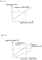
- Fig. 3 is a view showing the relation between the temperature and pressure of the mixed gas.
- This target pressure is a target value of the pressure of the mixed gas to be injected from the injection valve 3.
- the lower the temperature of the mixed gas before heating the larger becomes the electric power or electric energy which is required for raising the pressure of the mixed gas to the target pressure.
- the electric power to be supplied to the heating device 36 is made to change according to the temperature of the mixed gas at the time the mixed gas passes through the heating device 36, the electric power to be supplied becomes larger as the temperature of the mixed gas is lower.
- the temperature of the mixed gas is adjusted by adjusting a period of time to supply electric power to the heating device 36, while making constant the electric power to be supplied to the heating device 36, the lower the temperature of the mixed gas, the longer becomes the period of time to supply electric power, so electric energy becomes large.
- Fig. 4 is a view showing the relation between the electric power supplied to the heating device 36 when heating is carried out by the heating device 36, and the temperature of the mixed gas after heating.
- a solid line represents a case where the temperature of the cooling water in the internal combustion engine 1 is relatively high, and an alternate long and short dash line represents a case where the temperature of the cooling water of the internal combustion engine 1 is relatively low.
- the electric power to be supplied is limited to the threshold.
- an upper limit may be set for the electric power to be supplied.
- This threshold value is a value at the time when the electric power is on the boundary of whether to exceed an allowable range.
- the threshold value is electric power which can heat the reducing agent to a sufficient temperature to suppress condensation of the reducing agent.
- the threshold value is also electric power which is not enough to suppress condensation of the reducing agent.
- electric energy may be used in place of electric power. In this manner, the temperature of the mixed gas is made not to rise to the target temperature. In that case, the temperature of the mixed gas becomes low, so the pressure of the mixed gas to be injected from the injection valve 3 becomes low.
- the determination as to whether to limit the electric power may be made based on the temperature of the cooling water in the internal combustion engine 1 or the temperature of the mixed gas. For example, in cases where the temperature of the cooling water in the internal combustion engine 1 is equal to or less than a threshold value, or in cases where the temperature of the mixed gas is equal to or less than the threshold value, the electric power to be supplied is limited to the threshold value. In addition, in cases where an amount of rise in the temperature of the mixed gas is equal to or greater than a threshold value, the electric power to be supplied is limited to the threshold value. This decreases the temperature and pressure of the mixed gas to be supplied from the injection valve 3.
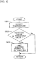
- Fig. 5 is a flow chart showing a flow or routine of heating control for the mixed gas according to this embodiment. This routine is carried out by means of the ECU 10 at the time of supplying the reducing agent.
- step S201 the temperature of the mixed gas is detected by the temperature sensor 12.
- the temperature of the cooling water in the internal combustion engine 1 may instead be detected.
- step S202 it is determined whether the temperature detected in step S201 is equal to or less than its threshold value.
- the threshold value referred to herein is set as a value at which the electric power to be supplied for heating the mixed gas to the required temperature exceeds the allowable range. That is, the threshold value is set to a value at the time when the deterioration of fuel economy exceeds the allowable range. This value has been beforehand obtained through experiments, etc., and stored in the ECU 10. In cases where an affirmative determination is made in step S202, the routine advances to step S203.
- step S203 the electric power to be supplied is limited.
- the electric power to be supplied is set to be a threshold value which is shown in Fig. 4 .
- the temperature of the mixed gas does not become high, so there is a fear that the reducing agent may condense.
- the electric power to be supplied may be set to a value which is lower than the threshold value.
- the electric power to be supplied, which is set at this time, may be decided based on the temperature of the cooling water in the internal combustion engine 1 or the temperature of the mixed gas.
- the threshold value may be decided according to which and how much priority is given between the suppression of the deterioration of fuel economy, and the suppression of condensation of the reducing agent.
- step S202 the mixed gas is heated, as in the first embodiment.
Landscapes
- Chemical & Material Sciences (AREA)
- Engineering & Computer Science (AREA)
- Chemical Kinetics & Catalysis (AREA)
- Health & Medical Sciences (AREA)
- Toxicology (AREA)
- Combustion & Propulsion (AREA)
- Mechanical Engineering (AREA)
- General Engineering & Computer Science (AREA)
- Exhaust Gas After Treatment (AREA)
- Exhaust Gas Treatment By Means Of Catalyst (AREA)
Claims (3)
- Abgasreinigungsvorrichtung für eine Brennkraftmaschine, die Folgendes aufweist:einen Abgasreinigungskatalysator (4), der in einem Abgasdurchgang (2) der Brennkraftmaschine (1) angeordnet ist;einen Tank (32), der ein Additiv in einem festen oder einem flüssigen Zustand speichert, das zu dem Abgasreinigungskatalysator (4) zugeführt wird und das als ein Reduktionsmittel oder ein Oxidationsmittel wirkt;eine Verdampfungsvorrichtung (38), die das feste oder flüssige Additiv durch ein Erwärmen desselben verdampft; undeinen Zuführdurchgang (31), der zwischen dem Tank (32) und dem Abgasdurchgang (2) auf der stromaufwärtigen Seite des Abgasreinigungskatalysators (4) verbindet, wobei ein gasförmiges Additiv, das durch die Verdampfungsvorrichtung (38) verdampft wird, dort hindurch strömt, wobei das gasförmige Additiv, das durch die Verdampfungsvorrichtung (38) verdampft wird, auf der stromaufwärtigen Seite des Abgasreinigungskatalysators (4) zu dem Abgasdurchgang (2) zugeführt wird;dadurch gekennzeichnet, dass die Abgasreinigungsvorrichtung Folgendes aufweist:eine Verdünnungsvorrichtung (5), die das gasförmige Additiv mit einem anderen Gas in dem Zuführdurchgang (31) verdünnt;eine Messvorrichtung (3), die in dem Zuführdurchgang (31) eine Menge des Additivs, das von dem Zuführdurchgang (31) zu dem Abgasdurchgang (2) zuzuführen ist, einstellt, nachdem es durch die Verdünnungsvorrichtung (5) verdünnt ist; undeine Einstellvorrichtung (36), die in dem Zuführdurchgang (31) auf der stromaufwärtigen Seite der Messvorrichtung (3) angeordnet ist, zum Einstellen der Temperatur oder eines Drucks des Additivs, das durch die Verdünnungsvorrichtung (5) verdünnt wurde.
- Abgasreinigungsvorrichtung für eine Brennkraftmaschine nach Anspruch 1, wobei
die Einstellvorrichtung (36) die Temperatur oder einen Druck des Additivs derart einstellt, dass die Temperatur des Additivs, nachdem es durch die Verdünnungsvorrichtung (5) verdünnt ist, höher als eine Kondensationspunkttemperatur von diesem wird. - Abgasreinigungsvorrichtung für eine Brennkraftmaschine nach Anspruch 1 oder 2, wobei
die Einstellvorrichtung (36) die Temperatur des Additivs einstellt, nachdem es durch die Verdünnungsvorrichtung (5) verdünnt ist, und die Einstellvorrichtung (36) den Druck des Additivs, das von dem Zuführdurchgang (31) zu dem Abgasdurchgang (2) zuzuführen ist, in Fällen niedriger macht, in denen der Wärmebetrag, der erforderlich ist, um die Temperatur des Additivs, das durch die Verdünnungsvorrichtung (5) verdünnt ist, höher als die Kondensationspunkttemperatur von diesem zu machen, gleich wie oder größer als ein Schwellenwert ist, als in Fällen, in denen sie geringer als der Schwellenwert ist.
Applications Claiming Priority (1)
| Application Number | Priority Date | Filing Date | Title |
|---|---|---|---|
| PCT/JP2012/052501 WO2013114614A1 (ja) | 2012-02-03 | 2012-02-03 | 内燃機関の排気浄化装置 |
Publications (4)
| Publication Number | Publication Date |
|---|---|
| EP2811129A1 EP2811129A1 (de) | 2014-12-10 |
| EP2811129A4 EP2811129A4 (de) | 2015-01-28 |
| EP2811129B1 true EP2811129B1 (de) | 2017-05-17 |
| EP2811129B8 EP2811129B8 (de) | 2017-09-27 |
Family
ID=48904690
Family Applications (1)
| Application Number | Title | Priority Date | Filing Date |
|---|---|---|---|
| EP12867208.6A Not-in-force EP2811129B8 (de) | 2012-02-03 | 2012-02-03 | Abgasreinigungsvorrichtung für einen verbrennungsmotor |
Country Status (3)
| Country | Link |
|---|---|
| EP (1) | EP2811129B8 (de) |
| JP (1) | JP5804090B2 (de) |
| WO (1) | WO2013114614A1 (de) |
Families Citing this family (1)
| Publication number | Priority date | Publication date | Assignee | Title |
|---|---|---|---|---|
| JP6140470B2 (ja) * | 2013-02-15 | 2017-05-31 | 日立造船株式会社 | 排ガス浄化システム |
Family Cites Families (11)
| Publication number | Priority date | Publication date | Assignee | Title |
|---|---|---|---|---|
| JP2951831B2 (ja) * | 1993-11-05 | 1999-09-20 | 三菱電機株式会社 | 内燃機関の排気ガス浄化装置 |
| JP3022601B2 (ja) * | 1994-09-13 | 2000-03-21 | シーメンス アクチエンゲゼルシヤフト | 排気ガス浄化装置に液体を供給する方法及び装置 |
| JPH09267025A (ja) * | 1996-03-29 | 1997-10-14 | Kawasaki Heavy Ind Ltd | 排ガス脱硝用還元剤の供給方法 |
| JP3831804B2 (ja) | 1998-02-24 | 2006-10-11 | 中国電力株式会社 | 排ガスの脱硝装置 |
| JPH11257049A (ja) * | 1998-03-10 | 1999-09-21 | Unisia Jecs Corp | 内燃機関の排気浄化装置 |
| US6363771B1 (en) * | 1999-11-24 | 2002-04-02 | Caterpillar Inc. | Emissions diagnostic system |
| US6834498B2 (en) * | 2002-11-21 | 2004-12-28 | Ford Global Technologies, Llc | Diesel aftertreatment systems |
| JP4137838B2 (ja) * | 2004-04-30 | 2008-08-20 | ボッシュ株式会社 | 排気ガス後処理装置用液体供給装置 |
| DE102004062603B3 (de) * | 2004-12-24 | 2006-07-27 | Eichenauer Heizelemente Gmbh & Co. Kg | Harnstoff-Dosiersystem für einen Abgasreinigungskatalysator eines Kfz und Ringheizung für ein solches Harnstoff-Dosiersystem |
| JP4888480B2 (ja) | 2008-12-15 | 2012-02-29 | 株式会社デンソー | 排気浄化システムの制御装置 |
| JP5346798B2 (ja) | 2009-12-25 | 2013-11-20 | 株式会社日本自動車部品総合研究所 | 排気浄化装置 |
-
2012
- 2012-02-03 EP EP12867208.6A patent/EP2811129B8/de not_active Not-in-force
- 2012-02-03 WO PCT/JP2012/052501 patent/WO2013114614A1/ja not_active Ceased
- 2012-02-03 JP JP2013556165A patent/JP5804090B2/ja not_active Expired - Fee Related
Also Published As
| Publication number | Publication date |
|---|---|
| EP2811129B8 (de) | 2017-09-27 |
| JP5804090B2 (ja) | 2015-11-04 |
| EP2811129A1 (de) | 2014-12-10 |
| EP2811129A4 (de) | 2015-01-28 |
| JPWO2013114614A1 (ja) | 2015-05-11 |
| WO2013114614A1 (ja) | 2013-08-08 |
Similar Documents
| Publication | Publication Date | Title |
|---|---|---|
| US5884475A (en) | Method and device for introducing liquid into an exhaust-gas purification system | |
| US11815000B2 (en) | Exhaust gas treatment system with improved low temperature performance | |
| US8234854B2 (en) | System and method for heating a reducing agent associated with a reducing agent distribution system | |
| RU2665193C2 (ru) | Способы снижения токсичности выхлопных газов (варианты) | |
| KR102309229B1 (ko) | 내연기관 | |
| US10301997B2 (en) | Method for checking a temperature sensor in an SCR exhaust gas post-treatment system | |
| US8677736B2 (en) | Exhaust gas purification apparatus of an internal combustion engine | |
| CN102016250B (zh) | 用于还原scr催化器上的nox排放物的装置、系统和方法 | |
| KR100697545B1 (ko) | 환원제를 계량하기 위한 방법 | |
| US10408103B1 (en) | Method to power multiple electric heaters with a single power source | |
| US8402750B2 (en) | Reagent tank normalizing system | |
| GB2537061A (en) | Apparatus, system and method for diesel exhaust fluid heating control | |
| KR101646438B1 (ko) | 요소탱크 온도제어방법 및 그 제어장치 | |
| EP2811129B1 (de) | Abgasreinigungsvorrichtung für einen verbrennungsmotor | |
| EP3342998B1 (de) | Abgasreinigungsvorrichtung für eine brennkraftmaschine | |
| EP2784279A1 (de) | Abgasreinigungsvorrichtung für einen verbrennungsmotor | |
| EP2273082A1 (de) | Vorrichtung zur Aufrechterhaltung einer Harnstofflösung in einem flüssigen Zustand zur Behandlung von Dieselabgas | |
| US20110005213A1 (en) | Apparatus for Maintaining a Urea Solution in a Liquid State for Treatment of Diesel Exhaust | |
| US10975749B2 (en) | Systems and methods for heating reductant | |
| US20070289288A1 (en) | Venting of on-board vehicle emissions treatment system with pressure assist | |
| EP2894310B1 (de) | Zusatzstoffzufuhrvorrichtung für verbrennungsmotoren | |
| KR100980631B1 (ko) | 에스씨알 시스템의 요소저장탱크와 요소공급라인의 가열장치 | |
| US11629624B1 (en) | DEF thawing apparatus and method for diesel engine SCR systems | |
| JP2022044264A (ja) | 還元剤供給システム、還元剤供給制御装置、および還元剤供給制御方法 | |
| JP2016205260A (ja) | 内燃機関の排気浄化システム |
Legal Events
| Date | Code | Title | Description |
|---|---|---|---|
| PUAI | Public reference made under article 153(3) epc to a published international application that has entered the european phase |
Free format text: ORIGINAL CODE: 0009012 |
|
| 17P | Request for examination filed |
Effective date: 20140806 |
|
| AK | Designated contracting states |
Kind code of ref document: A1 Designated state(s): AL AT BE BG CH CY CZ DE DK EE ES FI FR GB GR HR HU IE IS IT LI LT LU LV MC MK MT NL NO PL PT RO RS SE SI SK SM TR |
|
| AX | Request for extension of the european patent |
Extension state: BA ME |
|
| A4 | Supplementary search report drawn up and despatched |
Effective date: 20150108 |
|
| RIC1 | Information provided on ipc code assigned before grant |
Ipc: F01N 3/029 20060101ALI20141222BHEP Ipc: F01N 3/025 20060101ALI20141222BHEP Ipc: F01N 3/023 20060101ALI20141222BHEP Ipc: F01N 3/08 20060101AFI20141222BHEP |
|
| DAX | Request for extension of the european patent (deleted) | ||
| GRAP | Despatch of communication of intention to grant a patent |
Free format text: ORIGINAL CODE: EPIDOSNIGR1 |
|
| STAA | Information on the status of an ep patent application or granted ep patent |
Free format text: STATUS: GRANT OF PATENT IS INTENDED |
|
| INTG | Intention to grant announced |
Effective date: 20161214 |
|
| GRAS | Grant fee paid |
Free format text: ORIGINAL CODE: EPIDOSNIGR3 |
|
| GRAA | (expected) grant |
Free format text: ORIGINAL CODE: 0009210 |
|
| STAA | Information on the status of an ep patent application or granted ep patent |
Free format text: STATUS: THE PATENT HAS BEEN GRANTED |
|
| AK | Designated contracting states |
Kind code of ref document: B1 Designated state(s): AL AT BE BG CH CY CZ DE DK EE ES FI FR GB GR HR HU IE IS IT LI LT LU LV MC MK MT NL NO PL PT RO RS SE SI SK SM TR |
|
| REG | Reference to a national code |
Ref country code: GB Ref legal event code: FG4D |
|
| REG | Reference to a national code |
Ref country code: CH Ref legal event code: EP |
|
| REG | Reference to a national code |
Ref country code: IE Ref legal event code: FG4D |
|
| REG | Reference to a national code |
Ref country code: AT Ref legal event code: REF Ref document number: 894677 Country of ref document: AT Kind code of ref document: T Effective date: 20170615 |
|
| REG | Reference to a national code |
Ref country code: DE Ref legal event code: R096 Ref document number: 602012032690 Country of ref document: DE |
|
| GRAT | Correction requested after decision to grant or after decision to maintain patent in amended form |
Free format text: ORIGINAL CODE: EPIDOSNCDEC |
|
| REG | Reference to a national code |
Ref country code: NL Ref legal event code: MP Effective date: 20170517 |
|
| REG | Reference to a national code |
Ref country code: LT Ref legal event code: MG4D |
|
| REG | Reference to a national code |
Ref country code: AT Ref legal event code: MK05 Ref document number: 894677 Country of ref document: AT Kind code of ref document: T Effective date: 20170517 |
|
| PG25 | Lapsed in a contracting state [announced via postgrant information from national office to epo] |
Ref country code: ES Free format text: LAPSE BECAUSE OF FAILURE TO SUBMIT A TRANSLATION OF THE DESCRIPTION OR TO PAY THE FEE WITHIN THE PRESCRIBED TIME-LIMIT Effective date: 20170517 Ref country code: AT Free format text: LAPSE BECAUSE OF FAILURE TO SUBMIT A TRANSLATION OF THE DESCRIPTION OR TO PAY THE FEE WITHIN THE PRESCRIBED TIME-LIMIT Effective date: 20170517 Ref country code: GR Free format text: LAPSE BECAUSE OF FAILURE TO SUBMIT A TRANSLATION OF THE DESCRIPTION OR TO PAY THE FEE WITHIN THE PRESCRIBED TIME-LIMIT Effective date: 20170818 Ref country code: HR Free format text: LAPSE BECAUSE OF FAILURE TO SUBMIT A TRANSLATION OF THE DESCRIPTION OR TO PAY THE FEE WITHIN THE PRESCRIBED TIME-LIMIT Effective date: 20170517 Ref country code: FI Free format text: LAPSE BECAUSE OF FAILURE TO SUBMIT A TRANSLATION OF THE DESCRIPTION OR TO PAY THE FEE WITHIN THE PRESCRIBED TIME-LIMIT Effective date: 20170517 Ref country code: NO Free format text: LAPSE BECAUSE OF FAILURE TO SUBMIT A TRANSLATION OF THE DESCRIPTION OR TO PAY THE FEE WITHIN THE PRESCRIBED TIME-LIMIT Effective date: 20170817 Ref country code: LT Free format text: LAPSE BECAUSE OF FAILURE TO SUBMIT A TRANSLATION OF THE DESCRIPTION OR TO PAY THE FEE WITHIN THE PRESCRIBED TIME-LIMIT Effective date: 20170517 |
|
| REG | Reference to a national code |
Ref country code: DE Ref legal event code: R084 Ref document number: 602012032690 Country of ref document: DE |
|
| PG25 | Lapsed in a contracting state [announced via postgrant information from national office to epo] |
Ref country code: NL Free format text: LAPSE BECAUSE OF FAILURE TO SUBMIT A TRANSLATION OF THE DESCRIPTION OR TO PAY THE FEE WITHIN THE PRESCRIBED TIME-LIMIT Effective date: 20170517 Ref country code: PL Free format text: LAPSE BECAUSE OF FAILURE TO SUBMIT A TRANSLATION OF THE DESCRIPTION OR TO PAY THE FEE WITHIN THE PRESCRIBED TIME-LIMIT Effective date: 20170517 Ref country code: IS Free format text: LAPSE BECAUSE OF FAILURE TO SUBMIT A TRANSLATION OF THE DESCRIPTION OR TO PAY THE FEE WITHIN THE PRESCRIBED TIME-LIMIT Effective date: 20170917 Ref country code: LV Free format text: LAPSE BECAUSE OF FAILURE TO SUBMIT A TRANSLATION OF THE DESCRIPTION OR TO PAY THE FEE WITHIN THE PRESCRIBED TIME-LIMIT Effective date: 20170517 Ref country code: SE Free format text: LAPSE BECAUSE OF FAILURE TO SUBMIT A TRANSLATION OF THE DESCRIPTION OR TO PAY THE FEE WITHIN THE PRESCRIBED TIME-LIMIT Effective date: 20170517 Ref country code: RS Free format text: LAPSE BECAUSE OF FAILURE TO SUBMIT A TRANSLATION OF THE DESCRIPTION OR TO PAY THE FEE WITHIN THE PRESCRIBED TIME-LIMIT Effective date: 20170517 Ref country code: BG Free format text: LAPSE BECAUSE OF FAILURE TO SUBMIT A TRANSLATION OF THE DESCRIPTION OR TO PAY THE FEE WITHIN THE PRESCRIBED TIME-LIMIT Effective date: 20170817 |
|
| PG25 | Lapsed in a contracting state [announced via postgrant information from national office to epo] |
Ref country code: RO Free format text: LAPSE BECAUSE OF FAILURE TO SUBMIT A TRANSLATION OF THE DESCRIPTION OR TO PAY THE FEE WITHIN THE PRESCRIBED TIME-LIMIT Effective date: 20170517 Ref country code: CZ Free format text: LAPSE BECAUSE OF FAILURE TO SUBMIT A TRANSLATION OF THE DESCRIPTION OR TO PAY THE FEE WITHIN THE PRESCRIBED TIME-LIMIT Effective date: 20170517 Ref country code: DK Free format text: LAPSE BECAUSE OF FAILURE TO SUBMIT A TRANSLATION OF THE DESCRIPTION OR TO PAY THE FEE WITHIN THE PRESCRIBED TIME-LIMIT Effective date: 20170517 Ref country code: EE Free format text: LAPSE BECAUSE OF FAILURE TO SUBMIT A TRANSLATION OF THE DESCRIPTION OR TO PAY THE FEE WITHIN THE PRESCRIBED TIME-LIMIT Effective date: 20170517 Ref country code: SK Free format text: LAPSE BECAUSE OF FAILURE TO SUBMIT A TRANSLATION OF THE DESCRIPTION OR TO PAY THE FEE WITHIN THE PRESCRIBED TIME-LIMIT Effective date: 20170517 |
|
| REG | Reference to a national code |
Ref country code: DE Ref legal event code: R097 Ref document number: 602012032690 Country of ref document: DE |
|
| PG25 | Lapsed in a contracting state [announced via postgrant information from national office to epo] |
Ref country code: IT Free format text: LAPSE BECAUSE OF FAILURE TO SUBMIT A TRANSLATION OF THE DESCRIPTION OR TO PAY THE FEE WITHIN THE PRESCRIBED TIME-LIMIT Effective date: 20170517 Ref country code: SM Free format text: LAPSE BECAUSE OF FAILURE TO SUBMIT A TRANSLATION OF THE DESCRIPTION OR TO PAY THE FEE WITHIN THE PRESCRIBED TIME-LIMIT Effective date: 20170517 |
|
| PLBE | No opposition filed within time limit |
Free format text: ORIGINAL CODE: 0009261 |
|
| STAA | Information on the status of an ep patent application or granted ep patent |
Free format text: STATUS: NO OPPOSITION FILED WITHIN TIME LIMIT |
|
| 26N | No opposition filed |
Effective date: 20180220 |
|
| PG25 | Lapsed in a contracting state [announced via postgrant information from national office to epo] |
Ref country code: SI Free format text: LAPSE BECAUSE OF FAILURE TO SUBMIT A TRANSLATION OF THE DESCRIPTION OR TO PAY THE FEE WITHIN THE PRESCRIBED TIME-LIMIT Effective date: 20170517 |
|
| REG | Reference to a national code |
Ref country code: CH Ref legal event code: PL |
|
| PG25 | Lapsed in a contracting state [announced via postgrant information from national office to epo] |
Ref country code: MC Free format text: LAPSE BECAUSE OF FAILURE TO SUBMIT A TRANSLATION OF THE DESCRIPTION OR TO PAY THE FEE WITHIN THE PRESCRIBED TIME-LIMIT Effective date: 20170517 |
|
| GBPC | Gb: european patent ceased through non-payment of renewal fee |
Effective date: 20180203 |
|
| REG | Reference to a national code |
Ref country code: IE Ref legal event code: MM4A |
|
| REG | Reference to a national code |
Ref country code: BE Ref legal event code: MM Effective date: 20180228 |
|
| PG25 | Lapsed in a contracting state [announced via postgrant information from national office to epo] |
Ref country code: CH Free format text: LAPSE BECAUSE OF NON-PAYMENT OF DUE FEES Effective date: 20180228 Ref country code: LU Free format text: LAPSE BECAUSE OF NON-PAYMENT OF DUE FEES Effective date: 20180203 Ref country code: LI Free format text: LAPSE BECAUSE OF NON-PAYMENT OF DUE FEES Effective date: 20180228 |
|
| REG | Reference to a national code |
Ref country code: FR Ref legal event code: ST Effective date: 20181031 |
|
| PG25 | Lapsed in a contracting state [announced via postgrant information from national office to epo] |
Ref country code: IE Free format text: LAPSE BECAUSE OF NON-PAYMENT OF DUE FEES Effective date: 20180203 |
|
| PG25 | Lapsed in a contracting state [announced via postgrant information from national office to epo] |
Ref country code: FR Free format text: LAPSE BECAUSE OF NON-PAYMENT OF DUE FEES Effective date: 20180228 Ref country code: BE Free format text: LAPSE BECAUSE OF NON-PAYMENT OF DUE FEES Effective date: 20180228 Ref country code: GB Free format text: LAPSE BECAUSE OF NON-PAYMENT OF DUE FEES Effective date: 20180203 |
|
| PG25 | Lapsed in a contracting state [announced via postgrant information from national office to epo] |
Ref country code: MT Free format text: LAPSE BECAUSE OF NON-PAYMENT OF DUE FEES Effective date: 20180203 |
|
| PG25 | Lapsed in a contracting state [announced via postgrant information from national office to epo] |
Ref country code: TR Free format text: LAPSE BECAUSE OF FAILURE TO SUBMIT A TRANSLATION OF THE DESCRIPTION OR TO PAY THE FEE WITHIN THE PRESCRIBED TIME-LIMIT Effective date: 20170517 |
|
| PG25 | Lapsed in a contracting state [announced via postgrant information from national office to epo] |
Ref country code: PT Free format text: LAPSE BECAUSE OF FAILURE TO SUBMIT A TRANSLATION OF THE DESCRIPTION OR TO PAY THE FEE WITHIN THE PRESCRIBED TIME-LIMIT Effective date: 20170517 Ref country code: HU Free format text: LAPSE BECAUSE OF FAILURE TO SUBMIT A TRANSLATION OF THE DESCRIPTION OR TO PAY THE FEE WITHIN THE PRESCRIBED TIME-LIMIT; INVALID AB INITIO Effective date: 20120203 |
|
| PG25 | Lapsed in a contracting state [announced via postgrant information from national office to epo] |
Ref country code: MK Free format text: LAPSE BECAUSE OF NON-PAYMENT OF DUE FEES Effective date: 20170517 Ref country code: CY Free format text: LAPSE BECAUSE OF FAILURE TO SUBMIT A TRANSLATION OF THE DESCRIPTION OR TO PAY THE FEE WITHIN THE PRESCRIBED TIME-LIMIT Effective date: 20170517 |
|
| PG25 | Lapsed in a contracting state [announced via postgrant information from national office to epo] |
Ref country code: AL Free format text: LAPSE BECAUSE OF FAILURE TO SUBMIT A TRANSLATION OF THE DESCRIPTION OR TO PAY THE FEE WITHIN THE PRESCRIBED TIME-LIMIT Effective date: 20170517 |
|
| PGFP | Annual fee paid to national office [announced via postgrant information from national office to epo] |
Ref country code: DE Payment date: 20211230 Year of fee payment: 11 |
|
| P01 | Opt-out of the competence of the unified patent court (upc) registered |
Effective date: 20230427 |
|
| REG | Reference to a national code |
Ref country code: DE Ref legal event code: R119 Ref document number: 602012032690 Country of ref document: DE |
|
| PG25 | Lapsed in a contracting state [announced via postgrant information from national office to epo] |
Ref country code: DE Free format text: LAPSE BECAUSE OF NON-PAYMENT OF DUE FEES Effective date: 20230901 |