EP2811059B1 - Verfahren zur Bestimmung der Beladungsmenge in einem Wäschebehandlungsgerät - Google Patents
Verfahren zur Bestimmung der Beladungsmenge in einem Wäschebehandlungsgerät Download PDFInfo
- Publication number
- EP2811059B1 EP2811059B1 EP14169495.0A EP14169495A EP2811059B1 EP 2811059 B1 EP2811059 B1 EP 2811059B1 EP 14169495 A EP14169495 A EP 14169495A EP 2811059 B1 EP2811059 B1 EP 2811059B1
- Authority
- EP
- European Patent Office
- Prior art keywords
- image
- laundry
- treating
- generating
- graduated
- Prior art date
- Legal status (The legal status is an assumption and is not a legal conclusion. Google has not performed a legal analysis and makes no representation as to the accuracy of the status listed.)
- Not-in-force
Links
Images


Classifications
-
- D—TEXTILES; PAPER
- D06—TREATMENT OF TEXTILES OR THE LIKE; LAUNDERING; FLEXIBLE MATERIALS NOT OTHERWISE PROVIDED FOR
- D06F—LAUNDERING, DRYING, IRONING, PRESSING OR FOLDING TEXTILE ARTICLES
- D06F34/00—Details of control systems for washing machines, washer-dryers or laundry dryers
- D06F34/14—Arrangements for detecting or measuring specific parameters
- D06F34/18—Condition of the laundry, e.g. nature or weight
-
- D—TEXTILES; PAPER
- D06—TREATMENT OF TEXTILES OR THE LIKE; LAUNDERING; FLEXIBLE MATERIALS NOT OTHERWISE PROVIDED FOR
- D06F—LAUNDERING, DRYING, IRONING, PRESSING OR FOLDING TEXTILE ARTICLES
- D06F33/00—Control of operations performed in washing machines or washer-dryers
-
- D—TEXTILES; PAPER
- D06—TREATMENT OF TEXTILES OR THE LIKE; LAUNDERING; FLEXIBLE MATERIALS NOT OTHERWISE PROVIDED FOR
- D06F—LAUNDERING, DRYING, IRONING, PRESSING OR FOLDING TEXTILE ARTICLES
- D06F2101/00—User input for the control of domestic laundry washing machines, washer-dryers or laundry dryers
- D06F2101/02—Characteristics of laundry or load
- D06F2101/04—Quantity, e.g. weight
-
- D—TEXTILES; PAPER
- D06—TREATMENT OF TEXTILES OR THE LIKE; LAUNDERING; FLEXIBLE MATERIALS NOT OTHERWISE PROVIDED FOR
- D06F—LAUNDERING, DRYING, IRONING, PRESSING OR FOLDING TEXTILE ARTICLES
- D06F2101/00—User input for the control of domestic laundry washing machines, washer-dryers or laundry dryers
- D06F2101/20—Operation modes, e.g. delicate laundry washing programs, service modes or refreshment cycles
-
- D—TEXTILES; PAPER
- D06—TREATMENT OF TEXTILES OR THE LIKE; LAUNDERING; FLEXIBLE MATERIALS NOT OTHERWISE PROVIDED FOR
- D06F—LAUNDERING, DRYING, IRONING, PRESSING OR FOLDING TEXTILE ARTICLES
- D06F2103/00—Parameters monitored or detected for the control of domestic laundry washing machines, washer-dryers or laundry dryers
- D06F2103/02—Characteristics of laundry or load
-
- D—TEXTILES; PAPER
- D06—TREATMENT OF TEXTILES OR THE LIKE; LAUNDERING; FLEXIBLE MATERIALS NOT OTHERWISE PROVIDED FOR
- D06F—LAUNDERING, DRYING, IRONING, PRESSING OR FOLDING TEXTILE ARTICLES
- D06F2103/00—Parameters monitored or detected for the control of domestic laundry washing machines, washer-dryers or laundry dryers
- D06F2103/02—Characteristics of laundry or load
- D06F2103/04—Quantity, e.g. weight or variation of weight
-
- D—TEXTILES; PAPER
- D06—TREATMENT OF TEXTILES OR THE LIKE; LAUNDERING; FLEXIBLE MATERIALS NOT OTHERWISE PROVIDED FOR
- D06F—LAUNDERING, DRYING, IRONING, PRESSING OR FOLDING TEXTILE ARTICLES
- D06F2105/00—Systems or parameters controlled or affected by the control systems of washing machines, washer-dryers or laundry dryers
- D06F2105/58—Indications or alarms to the control system or to the user
-
- D—TEXTILES; PAPER
- D06—TREATMENT OF TEXTILES OR THE LIKE; LAUNDERING; FLEXIBLE MATERIALS NOT OTHERWISE PROVIDED FOR
- D06F—LAUNDERING, DRYING, IRONING, PRESSING OR FOLDING TEXTILE ARTICLES
- D06F33/00—Control of operations performed in washing machines or washer-dryers
- D06F33/30—Control of washing machines characterised by the purpose or target of the control
-
- D—TEXTILES; PAPER
- D06—TREATMENT OF TEXTILES OR THE LIKE; LAUNDERING; FLEXIBLE MATERIALS NOT OTHERWISE PROVIDED FOR
- D06F—LAUNDERING, DRYING, IRONING, PRESSING OR FOLDING TEXTILE ARTICLES
- D06F34/00—Details of control systems for washing machines, washer-dryers or laundry dryers
- D06F34/28—Arrangements for program selection, e.g. control panels therefor; Arrangements for indicating program parameters, e.g. the selected program or its progress
-
- D—TEXTILES; PAPER
- D06—TREATMENT OF TEXTILES OR THE LIKE; LAUNDERING; FLEXIBLE MATERIALS NOT OTHERWISE PROVIDED FOR
- D06F—LAUNDERING, DRYING, IRONING, PRESSING OR FOLDING TEXTILE ARTICLES
- D06F35/00—Washing machines, apparatus, or methods not otherwise provided for
- D06F35/005—Methods for washing, rinsing or spin-drying
- D06F35/006—Methods for washing, rinsing or spin-drying for washing or rinsing only
Definitions
- Laundry treating appliances such as clothes washers, clothes dryers, refreshers, and non-aqueous systems, may have a configuration based on a rotating drum that defines a treating chamber in which laundry items are placed for treating according to one or more cycles of operation.
- the laundry treating appliance may have a controller that implements the cycles of operation having one or more operating parameters.
- the cycles of operation may vary according to the size of the laundry load in the drum.
- the size of the laundry load may be manually input by the user through a user interface. Oftentimes a user will overestimate or underestimate the load size, thereby resulting in a less than optimal treating performance.
- laundry treating appliances currently measure mass but this may not provide a full understanding of the load size and may cause confusion for the user when mass is indicated.
- JP 2 991511 B2 discloses a laundry treating appliance according to the preamble of claim 15 and a method of determining a laundry load size therein according to the preamble of claim 1.
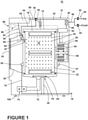
- FIG. 1 is a schematic view of a laundry treating appliance that may implement an embodiment of a method of the invention.
- the laundry treating appliance may be any appliance which performs a cycle of operation to clean or otherwise treat items placed therein, non-limiting examples of which include a horizontal or vertical axis clothes washer; a combination washing machine and dryer; a dispensing dryer; a tumbling or stationary refreshing/revitalizing machine; an extractor; a non-aqueous washing apparatus; and a revitalizing machine.
- the term "vertical-axis" washing machine refers to a washing machine having a rotatable drum that rotates about a generally vertical axis relative to a surface that supports the washing machine.
- the drum may rotate about an axis inclined relative to the vertical axis, with fifteen degrees of inclination being one example of the inclination.
- the term “horizontal-axis” washing machine refers to a washing machine having a rotatable drum that rotates about a generally horizontal axis relative to a surface that supports the washing machine.
- the drum may rotate about the axis inclined relative to the horizontal axis, with fifteen degrees of inclination being one example of the inclination.
- the laundry treating appliance of Figure 1 is illustrated as a horizontal-axis washing machine 10, which may include a structural support system including a cabinet 12 which defines a housing within which a laundry holding system resides.
- the cabinet 12 may be a housing having a chassis and/or a frame, defining an interior enclosing components typically found in a conventional washing machine, such as motors, pumps, fluid lines, controls, sensors, transducers, and the like. Such components will not be described further herein except as necessary for a complete understanding of the invention.
- the laundry holding system includes a tub 14 supported within the cabinet 12 by a suitable suspension system and a drum 16 provided within the tub 14, the drum 16 defining at least a portion of a laundry treating chamber 18 for receiving a laundry load for treatment.
- the drum 16 may include a plurality of perforations 20 such that liquid may flow between the tub 14 and the drum 16 through the perforations 20.
- Graduated markings 21 may be included on a portion of the laundry treating chamber 18 including on the drum 16, a rear bulkhead, a front bulkhead, a door/window, or a combination of the above. Multiple graduated markings 21 may be included on the laundry treating chamber 18 and any suitable type of graduated marking 21 may be included.
- the graduated markings may be formed in any suitable manner including that the graduated markings 21 may have a reflectance or a specific color to allow them to stand out better from the laundry treating chamber 18 and any laundry located therein.
- the graduated markings may be any suitable shape including lines, curves, etc. It is also contemplated that the plurality of perforations 20 may also form the graduated markings 21.
- a plurality of baffles 22 may be disposed on an inner surface of the drum 16 to lift the laundry load received in the treating chamber 18 while the drum 16 rotates. It may also be within the scope of the invention for the laundry holding system to include only a tub with the tub defining the laundry treating chamber.
- the laundry holding system may further include a door 24 which may be movably mounted to the cabinet 12 to selectively close both the tub 14 and the drum 16.
- a bellows 26 may couple an open face of the tub 14 with the cabinet 12, with the door 24 sealing against the bellows 26 when the door 24 closes the tub 14.
- the washing machine 10 may further include a suspension system 28 for dynamically suspending the laundry holding system within the structural support system.
- the washing machine 10 may also include at least one balance ring 38 containing a balancing material moveable within the balance ring 38 to counterbalance an imbalance that may be caused by laundry in the treating chamber 18 during rotation of the drum 16. More specifically, the balance ring 38 may be coupled with the rotating drum 16 and configured to compensate for a dynamic imbalance during rotation of the rotatable drum 16.
- the balancing material may be in the form of balls, fluid, or a combination thereof.
- the balance ring 38 may extend circumferentially around a periphery of the drum 16 and may be located at any desired location along an axis of rotation of the drum 16. When multiple balance rings 38 are present, they may be equally spaced along the axis of rotation of the drum 16. For example, in the illustrated example a plurality of balance rings 38 are included in the washing machine 10 and the plurality of balance rings 38 are operably coupled with opposite ends of the rotatable drum 16.
- the washing machine 10 may further include a liquid supply system for supplying water to the washing machine 10 for use in treating laundry during a cycle of operation.
- the liquid supply system may include a source of water, such as a household water supply 40, which may include separate valves 42 and 44 for controlling the flow of hot and cold water, respectively.
- Water may be supplied through an inlet conduit 46 directly to the tub 14 by controlling first and second diverter mechanisms 48 and 50, respectively.
- the diverter mechanisms 48, 50 may be a diverter valve having two outlets such that the diverter mechanisms 48, 50 may selectively direct a flow of liquid to one or both of two flow paths.
- Water from the household water supply 40 may flow through the inlet conduit 46 to the first diverter mechanism 48 which may direct the flow of liquid to a supply conduit 52.
- the second diverter mechanism 50 on the supply conduit 52 may direct the flow of liquid to a tub outlet conduit 54 which may be provided with a spray nozzle 56 configured to spray the flow of liquid into the tub 14. In this manner, water from the household water supply 40 may be supplied directly to the tub 14.
- the washing machine 10 may also be provided with a dispensing system for dispensing treating chemistry to the treating chamber 18 for use in treating the laundry according to a cycle of operation.
- the dispensing system may include a dispenser 62 which may be a single use dispenser, a bulk dispenser or a combination of a single use and bulk dispenser.
- the dispenser 62 may be configured to dispense a treating chemistry directly to the tub 14 or mixed with water from the liquid supply system through a dispensing outlet conduit 64.
- the dispensing outlet conduit 64 may include a dispensing nozzle 66 configured to dispense the treating chemistry into the tub 14 in a desired pattern and under a desired amount of pressure.
- the dispensing nozzle 66 may be configured to dispense a flow or stream of treating chemistry into the tub 14 by gravity, i.e. a non-pressurized stream.
- Water may be supplied to the dispenser 62 from the supply conduit 52 by directing the diverter mechanism 50 to direct the flow of water to a dispensing supply conduit 68.
- Non-limiting examples of treating chemistries that may be dispensed by the dispensing system during a cycle of operation include one or more of the following: water, enzymes, fragrances, stiffness/sizing agents, wrinkle releasers/reducers, softeners, antistatic or electrostatic agents, stain repellants, water repellants, energy reduction/extraction aids, antibacterial agents, medicinal agents, vitamins, moisturizers, shrinkage inhibitors, and color fidelity agents, and combinations thereof.
- the washing machine 10 may also include a recirculation and drain system for recirculating liquid within the laundry holding system and draining liquid from the washing machine 10.
- Liquid supplied to the tub 14 through the tub outlet conduit 54 and/or the dispensing supply conduit 68 typically enters a space between the tub 14 and the drum 16 and may flow by gravity to a sump 70 formed in part by a lower portion of the tub 14.
- the sump 70 may also be formed by a sump conduit 72 that may fluidly couple the lower portion of the tub 14 to a pump 74.
- the pump 74 may direct liquid to a drain conduit 76, which may drain the liquid from the washing machine 10, or to a recirculation conduit 78, which may terminate at a recirculation inlet 80.
- the liquid supply and/or recirculation and drain system may be provided with a heating system which may include one or more devices for heating laundry and/or liquid supplied to the tub 14, such as a steam generator 82 and/or a sump heater 84.
- Liquid from the household water supply 40 may be provided to the steam generator 82 through the inlet conduit 46 by controlling the first diverter mechanism 48 to direct the flow of liquid to a steam supply conduit 86.
- Steam generated by the steam generator 82 may be supplied to the tub 14 through a steam outlet conduit 87.
- the steam generator 82 may be any suitable type of steam generator such as a flow through steam generator or a tank-type steam generator.
- the sump heater 84 may be used to generate steam in place of or in addition to the steam generator 82.
- the steam generator 82 and/or sump heater 84 may be used to heat the laundry and/or liquid within the tub 14 as part of a cycle of operation.
- liquid supply and recirculation and drain system may differ from the configuration shown in Figure 1 , such as by inclusion of other valves, conduits, treating chemistry dispensers, sensors, such as water level sensors and temperature sensors, and the like, to control the flow of liquid through the washing machine 10 and for the introduction of more than one type of treating chemistry.
- the washing machine 10 also includes a drive system for rotating the drum 16 within the tub 14.
- the drive system may include a motor 88 for rotationally driving the drum 16.
- the motor 88 may be directly coupled with the drum 16 through a drive shaft 90 to rotate the drum 16 about a rotational axis during a cycle of operation.
- the motor 88 may be a brushless permanent magnet (BPM) motor having a stator 92 and a rotor 94. Alternately, the motor 88 may be coupled with the drum 16 through a belt and a drive shaft to rotate the drum 16, as is known in the art.
- Other motors such as an induction motor or a permanent split capacitor (PSC) motor, may also be used.
- the motor 88 may rotationally drive the drum 16 including that the motor 88 may rotate the drum 16 at various speeds in either rotational direction.
- An imaging device 95 may be configured to image the treating chamber 18 and/or anything within the treating chamber 18.
- Exemplary imaging devices 95 may include any optical sensor capable of capturing still or moving images, such as a camera.
- One suitable type of camera may be a CMOS camera.
- Other exemplary imaging devices include a CCD camera, a digital camera, a video camera or any other type of device capable of capturing an image. That camera may capture either or both visible and non-visible radiation.
- the camera may capture an image using visible light.
- the camera may capture an image using non-visible light, such as ultraviolet light.
- the camera may be a thermal imaging device capable of detecting radiation in the infrared region of the electromagnetic spectrum.
- the imaging device 95 may be located on either of the rear or front bulkhead, in the door 24, or on the drum 16. It may be readily understood that the location of the imaging device 95 may be in numerous other locations depending on the particular structure of the washing machine 10 and the desired position for obtaining an image. The location of the imaging device may depend on the type of desired image, the area of interest within the treating chamber 18, or whether the image may be captured with the drum in motion. For example, if the drum 16 is to be stopped during imaging and the laundry load is of interest, the imaging device 95 may be positioned so that its field of view includes the bottom and back of the drum 16. The imaging device may also be placed such that the entire or substantially the entire treating chamber 18 is within the field of view of the imaging device 95. There may also be multiple imaging devices, which may imaging the same or different areas of the treating chamber 18.
- An illumination source 97 may also be included to illuminate a portion of the laundry treating chamber 18.
- the type of illumination source 97 may vary.
- the illumination source 97 may be an incandescent light, one or more LED lights, etc.
- the illumination source 97 may also be located in any suitable location. While only a single illumination source 97 has been illustrated any number of illumination sources may be included including that an array of LED lights may be placed at multiple positions on a front bulkhead.
- the illumination source 97 may be located on the same side of the drum 16 as the imaging device 95, as illustrated, or may be located on a different side of the drum 16.
- the imaging device 95 may detect the light that may be reflected by the drum 16, the laundry load, and the graduated markings 21. Image analysis may then be used to isolate the drum 16, the laundry load, and the graduated markings 21. At any instant in time, a given location in an image will be dark or light depending on whether or not laundry is present at that location.
- the illumination generated by the illumination source may vary, and may well be dependent on the type of imaging device.
- the illumination may be infrared if the imaging device may be configured to image the infrared spectrum.
- the illumination may be visible light, if the imaging device may be configured to image the visible spectrum.
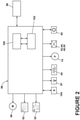
- the washing machine 10 also includes a control system for controlling the operation of the washing machine 10 to implement one or more cycles of operation.
- the control system may include a controller 96 located within the cabinet 12 and a user interface 98 that may be operably coupled with the controller 96.
- the user interface 98 may include one or more knobs, dials, switches, displays, touch screens and the like for communicating with the user, such as to receive input and provide output.
- the user may enter different types of information including, without limitation, cycle selection and cycle parameters, such as cycle options.
- the controller 96 may include the machine controller and any additional controllers provided for controlling any of the components of the washing machine 10.
- the controller 96 may include the machine controller and a motor controller.
- Many known types of controllers may be used for the controller 96.
- the specific type of controller is not germane to the invention.
- the controller may be a microprocessor-based controller that implements control software and sends/receives one or more electrical signals to/from each of the various working components to effect the control software.
- proportional control (P), proportional integral control (PI), and proportional derivative control (PD), or a combination thereof, a proportional integral derivative control (PID control) may be used to control the various components.
- the controller 96 may be provided with a memory 100 and a central processing unit (CPU) 102.
- the memory 100 may be used for storing the control software that may be executed by the CPU 102 in completing a cycle of operation using the washing machine 10 and any additional software. Examples, without limitation, of cycles of operation include: wash, heavy duty wash, delicate wash, quick wash, pre-wash, refresh, rinse only, and timed wash.
- the memory 100 may also be used to store information, such as a database or table, and to store data received from one or more components of the washing machine 10 that may be communicably coupled with the controller 96.
- the database or table may be used to store the various operating parameters for the one or more cycles of operation, including factory default values for the operating parameters and any adjustments to them by the control system or by user input. For example, a table of a plurality of threshold values 120 may be included.
- the controller 96 may be operably coupled with one or more components of the washing machine 10 for communicating with and controlling the operation of the component to complete a cycle of operation.
- the controller 96 may be operably coupled with the motor 88, the pump 74, the dispenser 62, the steam generator 82 and the sump heater 84 to control the operation of these and other components to implement one or more of the cycles of operation.
- the controller 96 may also be coupled with one or more sensors 104 provided in one or more of the systems of the washing machine 10 to receive input from the sensors, which are known in the art and not shown for simplicity.
- sensors 104 that may be communicably coupled with the controller 96 include: a treating chamber temperature sensor, a moisture sensor, a weight sensor, a chemical sensor, a position sensor, an imbalance sensor, a load size sensor, and a motor torque sensor, which may be used to determine a variety of system and laundry characteristics, such as laundry load inertia or mass.
- Figure 3A illustrates alternative graduated markings 112 that may be included in the treating chamber 18 of the washing machine 10. More specifically the graduated markings 112 have been illustrated on a rear bulkhead of the drum 16. The graduated markings 112 are linear and are uniformly spaced. Conversely, another set of alternative graduated markings 114 are shown in Figure 3B , which are similar to those of Figure 3A except they are non-uniformly spaced with larger spacing towards the bottom of the drum 16 and small spacing towards the top of the drum 16. In this manner, a portion of the multiple graduated markings 114 increase in number per unit height of the drum 16 as the multiple graduated markings 114 go up in height. This allows for more accurate size determination when laundry begins to fill the upper portions of the drum 16.
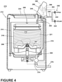
- FIG 4 illustrates an alternative laundry treating appliance in the form of a vertical-axis washing machine 210.
- the vertical axis washing machine 210 is similar to the horizontal-axis washing machine 10 illustrated in Figure 1 . Therefore, like parts will be identified with like numerals increased by 200, with it being understood that the description of the like parts of the horizontal-axis washing machine applies to the vertical-axis washing machine embodiment, unless otherwise noted.
- the washing machine 210 includes a perforated, open top drum 216 rotatably mounted inside the wash tub 214 and includes an agitator 291 or other type of clothes load and/or wash liquid mover rotatably mounted therein, as is well known in the washing machine art.
- graduated markings 221, in this case curved graduated markings 221 are formed on the interior of the drum 216. While the graduated markings 221 are illustrated as rings that go up the side of the open top drum 216, the graduated markings 221 may be shaped and arranged in any suitable manner.
- the markings may be continuously or discontinuously formed around the open top drum 216 so that the open top drum 216 may be in any rotational position and the graduated markings 221 may still be imaged as needed.
- an imaging device 295 may be included in the washing machine 210 and may be configured to image the treating chamber 218 and/or anything within the treating chamber 218. The imaging device 295 may be located in any suitable location so that it may image the treating chamber 218 including on the door 224, on a portion of the tub 214, or on a portion of the drum 216.
- the controller 296 may also be coupled with the imaging device 295 to capture one or more images of the treating chamber 218, any laundry 299 therein, and at least one graduated marking 221.
- the captured images may be sent to the controller 296 and analyzed using analysis software stored in the controller memory 300 to detect at least one graduated marking 221 in the generated image.
- the controller 296 may use the detection of the at least one graduated marking to determine a load size of the laundry within the treating chamber 218.
- FIG. 5 a flow chart of a method 320 for determining a laundry load size in a laundry treating appliance, such as the washing machine 10 and the washing machine 210, is illustrated. While each of the washing machines may implement the method 320, for ease of explanation the method 320 will be explained with respect to the washing machine 10.
- the sequence of steps depicted for this method is for illustrative purposes only, and is not meant to limit the method in any way as it is understood that the steps may proceed in a different logical order or additional or intervening steps may be included without detracting from the invention.
- the method 320 may be implemented in any suitable manner, such as automatically or manually, as a stand-alone phase or cycle of operation or as a phase of an operation cycle of the washing machine 10.
- the method 320 may also be implemented while a user may be loading the washing machine 10 to aid in alerting the user as to the size of the laundry load in the washing machine 10.
- the method 320 may start at step 322 while the user may be loading the washing machine 10 with one or more articles to form the laundry load, or when the laundry load may be loaded into the washing machine 10.
- the method 320 may be initiated automatically when the user opens or closes the door 24, or at the start of a user selected operating cycle.
- the imaging device 95 may generate an image of a portion of the treating chamber 18 having the graduated markings 21. Generating the image may include generating an image of multiple graduated markings 21 that are uniformly spaced or non-uniformly spaced within the treating chamber 18. Generating the image may include generating an image of at least one graduated marking 21 formed at any location, such as on a rear bulkhead of the laundry treating appliance or on the drum 16. Generating the image may include generating an image of at least one graduated marking 21 formed by at least one perforation 20 in the drum 16 or of at least one graduated marking 21 having a reflectance or specific color. The reflectance or specific color may be selected because the treating chamber 18 may be a wet environment that may be highly reflective and the graduated markings 21 are meant to stand out in such an environment.
- the controller 96 may detect at least one graduated marking 21 in the generated image. It is contemplated that laundry in the treating chamber 18 may cover a number of the graduated markings 21 and that a graduated marking 21 or a portion of the graduated marking 21 where laundry may not be blocking the graduated marking 21 may be detected in the image. The detecting may be done by having the generated image undergo image analysis. The generated image may be sent to the controller 96 for image analysis using software that may be stored in the memory 100 of the controller 96. The controller 96 may apply an algorithm to process the image. The algorithm may be implemented as a set of executable instructions that may be carried out by the CPU 102 in the controller 96.
- the imaging device 95 may have a memory and a microprocessor for storing information and software and executing the software, respectively. In this manner, the imaging device 95 may analyze the captured image data and communicate the results of the analysis with the controller 96.
- At least one graduated marking 21 may be isolated from the background, i.e. the drum 16, of the captured image. Isolating the at least one graduated marking 21 from the background may include identifying the at least one graduated marking 21 within the image or extracting one or more portions of the at least one graduated marking 21 from the image. Regardless of how the at least one graduated marking 21 may be isolated from the background, the at least one graduated marking 21 may be used to determine a load size of the laundry load within the drum 16 at 326. More specifically, based on the presence or absence of a graduated marking 21 in the image the controller 96 may determine the size of the laundry load.
- the determined at least one graduated marking 21 may be used to calculate the edge, volume, area, perimeter, radius and major or minor axis of the load using known methods.
- the controller 96 may be able to determine the load size based on the number of identified graduated markings 21 or the location of the identified graduated markings 21. For example, it will be understood that the larger the laundry load the more graduated markings 21 that will be covered by the larger laundry load and that the controller 96 may determine that the laundry load may be large based on which graduated markings 21 may be detected or how many, or few, graduated markings 21 may be detected.
- the image may be processed to count the number of graduated markings 21 visible in the image below the top graduated marking 21.
- the image may be processed to count the number of visible perforations 20.
- the count represents the "free" volume of the treating chamber 18, which may be equated with the "filled” volume.
- the "filled" volume for a particular "free" volume or graduated markings 21 count may be stored in a table in the memory 100 of the controller 96.
- detecting four graduated markings 21 may indicate that the drum 16 may be only half full while detecting only one graduated marking 21 may indicate that the drum 16 may be almost completely full.
- the number of graduated markings 21 may represent the height of the laundry load such that the height of the laundry load may be determined. From the height of the laundry load a volume of the laundry load may be estimated.
- the controller may use the determined load size to set one or more operating parameters of the treating cycle of operation to control the operation of at least one component with which the controller may be operably coupled with to complete a cycle of operation.
- the parameter that may be set may include a cycle time, an air flow rate in the treating chamber, a wash liquid fill level, a tumble pattern, an amount of treating chemistry, a type of treating chemistry, etc.
- the controller may also indicate a variety of information through the user interface based on the determined load size including the set cycle time and the determined load size.
- a type of laundry within the laundry load may be determined from the images. More specifically, different types of laundry items are known to lie differently and the laundry type may be determined based on such knowledge. For example, mountains and valleys in the laundry load may be determined in the generated image and the type of the load may be determined based on the mountains and valleys. Delicate fabric would lie more flat whereas a jeans load would have more mountains and valleys because they are of stiffer construction. Such information may also be utilized in setting a parameter of the cycle of operation. Further still information regarding the load may be transferred to a dryer or other laundry treating appliance where the laundry load may be intended to be subsequently transferred to.
- the above described embodiments provided a variety of benefits including that the size of the load may more accurately be determined.
- laundry treating appliances only measure a mass of the laundry load while users loads according to volume or how full they perceive the laundry treating appliance to be. Applying a strict mass sensor may be problematic for capacity detection because if a comforter which weighs about four pounds but is very voluminous is placed inside a washing machine the mass sensor would indicate that it is only a quarter full by mass but by volume it is taking up the entire space inside the drum. The customer may then get confused by the mass sensor and think that it is acceptable to put more fabric inside, which could reduce cleaning performance, cause the motor to overheat, etc.
- the above embodiments allow for a size determination of the laundry load that provides a good user experience. Further the above embodiments may be used to determine load type and may allow cycle parameters to be more accurately determined, which may result in energy, water consumption, and time savings as well as allowing the laundry treating appliance to be operated in an effective and efficient manner
- the different features and structures of the various embodiments may be used in combination with each other as desired. That one feature may not be illustrated in all of the embodiments is not meant to be construed that it may not be, but is done for brevity of description. Thus, the various features of the different embodiments may be mixed and matched as desired to form new embodiments, whether or not the new embodiments are expressly described. Further, it will be understood that any suitable image generation techniques may be used including that generating the image may include generating at least one of a still image or a video and may include capturing a digital image. Further, the image may be a visible light image, an ultraviolet light image, an infrared image, etc.
Landscapes
- Engineering & Computer Science (AREA)
- Textile Engineering (AREA)
- Control Of Washing Machine And Dryer (AREA)
Claims (15)
- Verfahren (320) zum Ermitteln einer Wäschebeladungsgröße in einem Wäschebehandlungsgerät (10; 210), das eine Drehtrommel (16; 216), die mindestens teilweise eine Behandlungskammer (18; 218) zum Aufnehmen von Wäsche zur Behandlung gemäß einem Behandlungsbetriebszyklus definiert, eine Bildgebungsvorrichtung (95; 295) und eine Steuereinheit (96; 296) mit einem Prozessor (102) umfasst, das Verfahren umfassend:Erzeugen (322) eines Bildes, mit der Bildgebungsvorrichtung (95; 295), eines Teils der Behandlungskammer (18; 218);dadurch gekennzeichnet, dass die Behandlungskammer (18; 218) graduierte Markierungen (21; 112; 114; 221) umfasst und das Verfahren umfasst:Erfassen (324), durch die Steuereinheit (96; 296), mindestens einer graduierten Markierung (21; 112; 114; 221) in dem erzeugten Bild; undErmitteln (326), durch die Steuereinheit (96; 296), einer Beladungsgröße basierend auf der mindestens einen graduierten Markierung (21; 112; 114; 221).
- Verfahren (320) nach Anspruch 1, wobei Erzeugen (322) des Bildes Erzeugen eines Bildes von mehreren graduierten Markierungen (112; 221) umfasst, die gleichförmig in der Behandlungskammer (18; 218) beabstandet sind.
- Verfahren (320) nach Anspruch 1, wobei Erzeugen (322) des Bildes Erzeugen eines Bildes von mehreren graduierten Markierungen (114) umfasst, die nicht gleichförmig in der Behandlungskammer (18) beabstandet sind.
- Verfahren (320) nach Anspruch 3, wobei Erzeugen (332) des Bildes der mehreren graduierten Markierungen (114) Erzeugen eines Bildes von mehreren graduierten Markierungen (114) umfasst, wo mindestens ein Teil der mehreren graduierten Markierungen (114) in Anzahl pro Höheneinheit zunimmt, während die mehreren graduierten Markierungen (114) in der Höhe steigen.
- Verfahren (320) nach einem der vorstehenden Ansprüche, wobei Erzeugen (322) des Bildes Erzeugen eines Bildes mindestens einer graduierten Markierung (21; 112; 114) umfasst, die an einer hinteren Trennwand des Wäschebehandlungsgeräts (10) gebildet ist.
- Verfahren (320) nach einem der vorstehenden Ansprüche, wobei Erzeugen (322) des Bildes Erzeugen eines Bildes mindestens einer graduierten Markierung (21) umfasst, die durch mindestens eine Perforation (20) in der Trommel (16) gebildet ist.
- Verfahren (320) nach einem der Ansprüche 1 bis 5, wobei Erzeugen (322) des Bildes Erzeugen eines Bildes mindestens einer graduierten Markierung (21; 112; 114; 221) mit einem Reflexionsgrad oder einer spezifischen Farbe umfasst.
- Verfahren (320) nach einem der vorstehenden Ansprüche, wobei das Ermitteln (326) der Beladungsgröße Ermitteln einer Höhe der Wäschebeladung basierend auf der erfassten mindestens einen graduierten Markierung (21; 112; 114; 221) umfasst.
- Verfahren (320) nach Anspruch 8, wobei das Ermitteln einer Beladungsgröße weiter Schätzen eines Volumens der Wäschebeladung basierend auf der ermittelten Höhe umfasst.
- Verfahren (320) nach einem der vorstehenden Ansprüche, wobei das Erzeugen (322) des Bildes Erzeugen mindestens eines von einem Standbild oder einem Video umfasst, optional weiter Aufnehmen eines digitalen Bildes umfasst, wobei das Bild ein Bild sichtbaren Lichts, ein Ultraviolettlichtbild oder ein Infrarotbild ist.
- Verfahren (320) nach einem der vorstehenden Ansprüche, wobei die mindestens eine graduierte Markierung (221) mindestens eine gekrümmte Graduierung umfasst, die auf der Trommel (216) gebildet ist.
- Verfahren (320) nach einem der vorstehenden Ansprüche, weiter umfassend Einstellen mindestens eines Parameters des Behandlungsbetriebszyklus basierend auf der ermittelten Beladungsgröße.
- Verfahren (320) nach Anspruch 12, wobei der mindestens eine Parameter eine Zykluszeit, eine Luftströmungsrate in der Behandlungskammer, ein Waschflüssigkeitsfüllstand oder eine Menge einer Behandlungschemikalie ist.
- Verfahren (320) nach einem der vorstehenden Ansprüche, weiter umfassend Angeben mindestens einer von der eingestellten Zykluszeit oder der ermittelten Beladungsgröße auf einer Benutzeroberfläche des Wäschebehandlungsgeräts (10; 210).
- Wäschebehandlungsgerät (10; 210), das eine Drehtrommel (16; 216), die mindestens teilweise eine Behandlungskammer (18; 218) zum Aufnehmen von Wäsche zur Behandlung gemäß einem Behandlungsbetriebszyklus definiert, eine Bildgebungsvorrichtung (95; 295) und eine Steuereinheit (96; 296) mit einem Prozessor (102) umfasst, dadurch gekennzeichnet, dass die Behandlungskammer graduierte Markierungen (21; 112; 114; 221) umfasst und die Steuereinheit (96; 296) angepasst ist, das Verfahren nach einem der vorstehenden Ansprüche auszuführen.
Applications Claiming Priority (1)
| Application Number | Priority Date | Filing Date | Title |
|---|---|---|---|
| US13/908,011 US9382654B2 (en) | 2013-06-03 | 2013-06-03 | Method of determining a load size in a laundry treating appliance |
Publications (2)
| Publication Number | Publication Date |
|---|---|
| EP2811059A1 EP2811059A1 (de) | 2014-12-10 |
| EP2811059B1 true EP2811059B1 (de) | 2022-03-23 |
Family
ID=50828711
Family Applications (1)
| Application Number | Title | Priority Date | Filing Date |
|---|---|---|---|
| EP14169495.0A Not-in-force EP2811059B1 (de) | 2013-06-03 | 2014-05-22 | Verfahren zur Bestimmung der Beladungsmenge in einem Wäschebehandlungsgerät |
Country Status (3)
| Country | Link |
|---|---|
| US (4) | US9382654B2 (de) |
| EP (1) | EP2811059B1 (de) |
| BR (1) | BR102014013347A2 (de) |
Families Citing this family (15)
| Publication number | Priority date | Publication date | Assignee | Title |
|---|---|---|---|---|
| EP2671994A1 (de) * | 2012-06-08 | 2013-12-11 | Electrolux Home Products Corporation N.V. | Wasserführendes Haushaltsgerät und zugehöriges Betriebsverfahren |
| DE102013208374B4 (de) * | 2013-05-07 | 2016-08-18 | Meiko Maschinenbau Gmbh & Co. Kg | Reinigungsvorrichtung mit beleuchtetem Türgriff |
| MX358870B (es) * | 2014-04-16 | 2018-09-04 | Mabe Sa De Cv | Sistema electronico inteligente para detectar previamente la condicion de sequedad de una carga de prendas textiles en una maquina automatica electronica secadora de ropa. |
| JP5896542B1 (ja) * | 2014-11-21 | 2016-03-30 | 株式会社ハッピー | 洗濯方法 |
| KR102478453B1 (ko) * | 2016-01-28 | 2022-12-16 | 엘지전자 주식회사 | 세탁장치 및 제어방법 |
| US20170298558A1 (en) * | 2016-04-15 | 2017-10-19 | The Procter & Gamble Company | Washing machines comprising load size indicators |
| DE102017209135A1 (de) * | 2017-05-31 | 2018-12-06 | BSH Hausgeräte GmbH | Verfahren zur Steuerung eines wasserführenden Haushaltsgerätes und hierzu geeignetes Haushaltsgerät |
| US10612175B2 (en) | 2017-09-28 | 2020-04-07 | Midea Group Co., Ltd. | Automatic color composition detection for laundry washing machine |
| CN109183354B (zh) * | 2018-11-09 | 2020-03-27 | 珠海格力电器股份有限公司 | 一种衣物防缠绕控制方法及装置 |
| CN110331551A (zh) * | 2019-05-24 | 2019-10-15 | 珠海格力电器股份有限公司 | 洗衣机的洗涤控制方法、装置、计算机设备和存储介质 |
| KR102799440B1 (ko) | 2019-07-26 | 2025-04-29 | 삼성전자주식회사 | 세탁기 및 그 제어 방법 |
| US11898289B2 (en) | 2020-12-18 | 2024-02-13 | Midea Group Co., Ltd. | Laundry washing machine calibration |
| US11773524B2 (en) | 2020-12-18 | 2023-10-03 | Midea Group Co., Ltd. | Laundry washing machine color composition analysis during loading |
| US11866868B2 (en) | 2020-12-18 | 2024-01-09 | Midea Group Co., Ltd. | Laundry washing machine color composition analysis with article alerts |
| US12006612B2 (en) | 2021-05-26 | 2024-06-11 | Haier Us Appliance Solutions, Inc. | Automated lens cleaning for a camera assembly based on image recognition in a washing machine appliance |
Citations (1)
| Publication number | Priority date | Publication date | Assignee | Title |
|---|---|---|---|---|
| US3611759A (en) * | 1970-03-18 | 1971-10-12 | Whirlpool Co | Water level control for automatic washing machine |
Family Cites Families (22)
| Publication number | Priority date | Publication date | Assignee | Title |
|---|---|---|---|---|
| DE3804624A1 (de) | 1988-02-13 | 1989-08-24 | Bauknecht Hausgeraete | Waschmaschine od. dgl. mit einer gewichtsanzeige fuer eingefuelltes waschgut |
| JP2991511B2 (ja) | 1991-01-29 | 1999-12-20 | 株式会社東芝 | 洗濯機 |
| EP0544945A1 (de) | 1991-12-05 | 1993-06-09 | The Procter & Gamble Company | Optische Prüfungsvorrichtung und Anordnung mit einer solcher Vorrichtung |
| US5515565A (en) * | 1994-05-20 | 1996-05-14 | Whirlpool Corporation | Wash liquid level control system for an automatic washer |
| WO2001096645A2 (en) | 2000-06-12 | 2001-12-20 | The Procter & Gamble Company | Method and system for optimizing performance of consumer appliances |
| JP2002224486A (ja) | 2001-02-01 | 2002-08-13 | Toshiba Corp | 洗濯機 |
| US6842532B2 (en) | 2001-02-08 | 2005-01-11 | The Hong Kong Polytechnic University | Three dimensional measurement, evaluation and grading system for fabric/textile structure/garment appearance |
| US7601978B2 (en) | 2002-04-11 | 2009-10-13 | Hamed Sari-Sarraf | Fabric wrinkle evaluation |
| US7380423B1 (en) | 2002-05-03 | 2008-06-03 | Musone John P | Combined washer dryer |
| NZ535898A (en) | 2003-04-11 | 2006-10-27 | Fisher & Paykel Appliances Ltd | Detection of drum position in laundry appliance |
| KR100778014B1 (ko) * | 2005-09-16 | 2007-11-21 | 한국건설기술연구원 | 영상을 이용한 액체 높이 측정 장치 및 방법 |
| FR2894996B1 (fr) | 2005-12-21 | 2011-08-12 | Brandt Ind | Machine a laver et/ou secher le linge et procede d'avertissement des parametres d'un cycle de lavage et/ou de sechage associe |
| GB2458927B (en) | 2008-04-02 | 2012-11-14 | Eykona Technologies Ltd | 3D Imaging system |
| US9745688B2 (en) | 2009-02-19 | 2017-08-29 | Whirlpool Corporation | Laundry treating appliance with load surface area detection |
| US8522452B2 (en) | 2009-02-19 | 2013-09-03 | Whirlpool Corporation | Laundry treating appliance with state of dryness based imaging control |
| US8528228B2 (en) | 2009-02-19 | 2013-09-10 | Whirlpool Corporation | Laundry treating appliance with drying rack detection based on imaging data |
| US8528229B2 (en) | 2009-02-19 | 2013-09-10 | Whirlpool Corporation | Laundry treating appliance with imaging control |
| US8528230B2 (en) | 2009-02-19 | 2013-09-10 | Whirlpool Corporation | Laundry treating appliance with bulky item detection |
| US8229204B2 (en) | 2009-06-29 | 2012-07-24 | Ecolab Inc. | Optical processing of surfaces to determine cleanliness |
| KR20110016189A (ko) * | 2009-08-11 | 2011-02-17 | 엘지전자 주식회사 | 세탁장치 및 이를 이용한 세탁방법 |
| US8696827B2 (en) | 2010-12-01 | 2014-04-15 | Whirlpool Corporation | Dishwasher with imaging device for measuring load characteristics and a method for controlling same |
| US20130042416A1 (en) | 2011-08-15 | 2013-02-21 | Whirlpool Corporation | Apparatus and method for determining a load amount in a laundry treating appliance during loading and providing indications regarding same |
-
2013
- 2013-06-03 US US13/908,011 patent/US9382654B2/en active Active
-
2014
- 2014-05-22 EP EP14169495.0A patent/EP2811059B1/de not_active Not-in-force
- 2014-06-02 BR BR102014013347A patent/BR102014013347A2/pt not_active Application Discontinuation
-
2016
- 2016-06-02 US US15/171,146 patent/US10156037B2/en active Active
-
2018
- 2018-10-17 US US16/162,970 patent/US11008692B2/en active Active
-
2021
- 2021-04-30 US US17/245,516 patent/US11686031B2/en active Active
Patent Citations (1)
| Publication number | Priority date | Publication date | Assignee | Title |
|---|---|---|---|---|
| US3611759A (en) * | 1970-03-18 | 1971-10-12 | Whirlpool Co | Water level control for automatic washing machine |
Also Published As
| Publication number | Publication date |
|---|---|
| US11008692B2 (en) | 2021-05-18 |
| EP2811059A1 (de) | 2014-12-10 |
| BR102014013347A2 (pt) | 2015-11-17 |
| US20210246593A1 (en) | 2021-08-12 |
| US20140352077A1 (en) | 2014-12-04 |
| US20160273146A1 (en) | 2016-09-22 |
| US20190048504A1 (en) | 2019-02-14 |
| US11686031B2 (en) | 2023-06-27 |
| US9382654B2 (en) | 2016-07-05 |
| US10156037B2 (en) | 2018-12-18 |
Similar Documents
| Publication | Publication Date | Title |
|---|---|---|
| US11686031B2 (en) | Method of determining a load size in a laundry treating appliance | |
| EP2811060B1 (de) | Verfahren zur Bestimmung einer Lastgröße in einem Wäschebehandlungsgerät | |
| US11655577B2 (en) | Laundry treating appliance and method of operation for a laundry treating appliance | |
| US9157177B2 (en) | Laundry treating appliance and method of control | |
| US9540756B2 (en) | Laundry treating appliance and method of filling a laundry treating appliance with liquid | |
| US10373770B2 (en) | Laundry treating appliance and method of operation for a laundry treating appliance | |
| CN112575497B (zh) | 用于根据自动操作循环处理衣物的衣物处理设备 | |
| US20150047396A1 (en) | Laundry treating appliance and method of predicting mechanical degradation in a laundry treating appliance | |
| US12270141B2 (en) | Laundry treating appliance for drying laundry | |
| US9469927B2 (en) | Laundry treating appliance and method of operating a laundry treating appliance | |
| US9145634B2 (en) | Method of operating a laundry treating appliance | |
| US20140317857A1 (en) | Laundry treating appliances and methods of controlling the same to balance small loads | |
| EP2684991B1 (de) | Betriebsverfahren einer Wäschebehandlungsmaschine |
Legal Events
| Date | Code | Title | Description |
|---|---|---|---|
| PUAI | Public reference made under article 153(3) epc to a published international application that has entered the european phase |
Free format text: ORIGINAL CODE: 0009012 |
|
| 17P | Request for examination filed |
Effective date: 20140522 |
|
| AK | Designated contracting states |
Kind code of ref document: A1 Designated state(s): AL AT BE BG CH CY CZ DE DK EE ES FI FR GB GR HR HU IE IS IT LI LT LU LV MC MK MT NL NO PL PT RO RS SE SI SK SM TR |
|
| AX | Request for extension of the european patent |
Extension state: BA ME |
|
| R17P | Request for examination filed (corrected) |
Effective date: 20150520 |
|
| RBV | Designated contracting states (corrected) |
Designated state(s): AL AT BE BG CH CY CZ DE DK EE ES FI FR GB GR HR HU IE IS IT LI LT LU LV MC MK MT NL NO PL PT RO RS SE SI SK SM TR |
|
| STAA | Information on the status of an ep patent application or granted ep patent |
Free format text: STATUS: EXAMINATION IS IN PROGRESS |
|
| 17Q | First examination report despatched |
Effective date: 20210414 |
|
| REG | Reference to a national code |
Ref country code: DE Ref legal event code: R079 Ref document number: 602014082915 Country of ref document: DE Free format text: PREVIOUS MAIN CLASS: D06F0039000000 Ipc: D06F0034180000 |
|
| GRAP | Despatch of communication of intention to grant a patent |
Free format text: ORIGINAL CODE: EPIDOSNIGR1 |
|
| STAA | Information on the status of an ep patent application or granted ep patent |
Free format text: STATUS: GRANT OF PATENT IS INTENDED |
|
| RIC1 | Information provided on ipc code assigned before grant |
Ipc: D06F 34/28 20200101ALN20211126BHEP Ipc: D06F 33/30 20200101ALN20211126BHEP Ipc: D06F 34/18 20200101AFI20211126BHEP |
|
| RIC1 | Information provided on ipc code assigned before grant |
Ipc: D06F 34/28 20200101ALN20211208BHEP Ipc: D06F 33/30 20200101ALN20211208BHEP Ipc: D06F 34/18 20200101AFI20211208BHEP |
|
| INTG | Intention to grant announced |
Effective date: 20220104 |
|
| RIN1 | Information on inventor provided before grant (corrected) |
Inventor name: MCALLISTER, KARL DAVID Inventor name: LEITERT, ANDREW |
|
| GRAS | Grant fee paid |
Free format text: ORIGINAL CODE: EPIDOSNIGR3 |
|
| GRAA | (expected) grant |
Free format text: ORIGINAL CODE: 0009210 |
|
| STAA | Information on the status of an ep patent application or granted ep patent |
Free format text: STATUS: THE PATENT HAS BEEN GRANTED |
|
| AK | Designated contracting states |
Kind code of ref document: B1 Designated state(s): AL AT BE BG CH CY CZ DE DK EE ES FI FR GB GR HR HU IE IS IT LI LT LU LV MC MK MT NL NO PL PT RO RS SE SI SK SM TR |
|
| REG | Reference to a national code |
Ref country code: GB Ref legal event code: FG4D |
|
| REG | Reference to a national code |
Ref country code: CH Ref legal event code: EP |
|
| REG | Reference to a national code |
Ref country code: DE Ref legal event code: R096 Ref document number: 602014082915 Country of ref document: DE |
|
| REG | Reference to a national code |
Ref country code: IE Ref legal event code: FG4D |
|
| REG | Reference to a national code |
Ref country code: AT Ref legal event code: REF Ref document number: 1477503 Country of ref document: AT Kind code of ref document: T Effective date: 20220415 |
|
| REG | Reference to a national code |
Ref country code: LT Ref legal event code: MG9D |
|
| REG | Reference to a national code |
Ref country code: NL Ref legal event code: MP Effective date: 20220323 |
|
| PG25 | Lapsed in a contracting state [announced via postgrant information from national office to epo] |
Ref country code: SE Free format text: LAPSE BECAUSE OF FAILURE TO SUBMIT A TRANSLATION OF THE DESCRIPTION OR TO PAY THE FEE WITHIN THE PRESCRIBED TIME-LIMIT Effective date: 20220323 Ref country code: RS Free format text: LAPSE BECAUSE OF FAILURE TO SUBMIT A TRANSLATION OF THE DESCRIPTION OR TO PAY THE FEE WITHIN THE PRESCRIBED TIME-LIMIT Effective date: 20220323 Ref country code: NO Free format text: LAPSE BECAUSE OF FAILURE TO SUBMIT A TRANSLATION OF THE DESCRIPTION OR TO PAY THE FEE WITHIN THE PRESCRIBED TIME-LIMIT Effective date: 20220623 Ref country code: LT Free format text: LAPSE BECAUSE OF FAILURE TO SUBMIT A TRANSLATION OF THE DESCRIPTION OR TO PAY THE FEE WITHIN THE PRESCRIBED TIME-LIMIT Effective date: 20220323 Ref country code: HR Free format text: LAPSE BECAUSE OF FAILURE TO SUBMIT A TRANSLATION OF THE DESCRIPTION OR TO PAY THE FEE WITHIN THE PRESCRIBED TIME-LIMIT Effective date: 20220323 Ref country code: BG Free format text: LAPSE BECAUSE OF FAILURE TO SUBMIT A TRANSLATION OF THE DESCRIPTION OR TO PAY THE FEE WITHIN THE PRESCRIBED TIME-LIMIT Effective date: 20220623 |
|
| REG | Reference to a national code |
Ref country code: AT Ref legal event code: MK05 Ref document number: 1477503 Country of ref document: AT Kind code of ref document: T Effective date: 20220323 |
|
| PG25 | Lapsed in a contracting state [announced via postgrant information from national office to epo] |
Ref country code: LV Free format text: LAPSE BECAUSE OF FAILURE TO SUBMIT A TRANSLATION OF THE DESCRIPTION OR TO PAY THE FEE WITHIN THE PRESCRIBED TIME-LIMIT Effective date: 20220323 Ref country code: GR Free format text: LAPSE BECAUSE OF FAILURE TO SUBMIT A TRANSLATION OF THE DESCRIPTION OR TO PAY THE FEE WITHIN THE PRESCRIBED TIME-LIMIT Effective date: 20220624 Ref country code: FI Free format text: LAPSE BECAUSE OF FAILURE TO SUBMIT A TRANSLATION OF THE DESCRIPTION OR TO PAY THE FEE WITHIN THE PRESCRIBED TIME-LIMIT Effective date: 20220323 |
|
| PG25 | Lapsed in a contracting state [announced via postgrant information from national office to epo] |
Ref country code: NL Free format text: LAPSE BECAUSE OF FAILURE TO SUBMIT A TRANSLATION OF THE DESCRIPTION OR TO PAY THE FEE WITHIN THE PRESCRIBED TIME-LIMIT Effective date: 20220323 |
|
| PG25 | Lapsed in a contracting state [announced via postgrant information from national office to epo] |
Ref country code: SM Free format text: LAPSE BECAUSE OF FAILURE TO SUBMIT A TRANSLATION OF THE DESCRIPTION OR TO PAY THE FEE WITHIN THE PRESCRIBED TIME-LIMIT Effective date: 20220323 Ref country code: SK Free format text: LAPSE BECAUSE OF FAILURE TO SUBMIT A TRANSLATION OF THE DESCRIPTION OR TO PAY THE FEE WITHIN THE PRESCRIBED TIME-LIMIT Effective date: 20220323 Ref country code: RO Free format text: LAPSE BECAUSE OF FAILURE TO SUBMIT A TRANSLATION OF THE DESCRIPTION OR TO PAY THE FEE WITHIN THE PRESCRIBED TIME-LIMIT Effective date: 20220323 Ref country code: PT Free format text: LAPSE BECAUSE OF FAILURE TO SUBMIT A TRANSLATION OF THE DESCRIPTION OR TO PAY THE FEE WITHIN THE PRESCRIBED TIME-LIMIT Effective date: 20220725 Ref country code: ES Free format text: LAPSE BECAUSE OF FAILURE TO SUBMIT A TRANSLATION OF THE DESCRIPTION OR TO PAY THE FEE WITHIN THE PRESCRIBED TIME-LIMIT Effective date: 20220323 Ref country code: EE Free format text: LAPSE BECAUSE OF FAILURE TO SUBMIT A TRANSLATION OF THE DESCRIPTION OR TO PAY THE FEE WITHIN THE PRESCRIBED TIME-LIMIT Effective date: 20220323 Ref country code: CZ Free format text: LAPSE BECAUSE OF FAILURE TO SUBMIT A TRANSLATION OF THE DESCRIPTION OR TO PAY THE FEE WITHIN THE PRESCRIBED TIME-LIMIT Effective date: 20220323 Ref country code: AT Free format text: LAPSE BECAUSE OF FAILURE TO SUBMIT A TRANSLATION OF THE DESCRIPTION OR TO PAY THE FEE WITHIN THE PRESCRIBED TIME-LIMIT Effective date: 20220323 |
|
| PG25 | Lapsed in a contracting state [announced via postgrant information from national office to epo] |
Ref country code: PL Free format text: LAPSE BECAUSE OF FAILURE TO SUBMIT A TRANSLATION OF THE DESCRIPTION OR TO PAY THE FEE WITHIN THE PRESCRIBED TIME-LIMIT Effective date: 20220323 Ref country code: IS Free format text: LAPSE BECAUSE OF FAILURE TO SUBMIT A TRANSLATION OF THE DESCRIPTION OR TO PAY THE FEE WITHIN THE PRESCRIBED TIME-LIMIT Effective date: 20220723 Ref country code: AL Free format text: LAPSE BECAUSE OF FAILURE TO SUBMIT A TRANSLATION OF THE DESCRIPTION OR TO PAY THE FEE WITHIN THE PRESCRIBED TIME-LIMIT Effective date: 20220323 |
|
| REG | Reference to a national code |
Ref country code: CH Ref legal event code: PL |
|
| REG | Reference to a national code |
Ref country code: DE Ref legal event code: R097 Ref document number: 602014082915 Country of ref document: DE |
|
| REG | Reference to a national code |
Ref country code: BE Ref legal event code: MM Effective date: 20220531 |
|
| PLBE | No opposition filed within time limit |
Free format text: ORIGINAL CODE: 0009261 |
|
| STAA | Information on the status of an ep patent application or granted ep patent |
Free format text: STATUS: NO OPPOSITION FILED WITHIN TIME LIMIT |
|
| PG25 | Lapsed in a contracting state [announced via postgrant information from national office to epo] |
Ref country code: MC Free format text: LAPSE BECAUSE OF FAILURE TO SUBMIT A TRANSLATION OF THE DESCRIPTION OR TO PAY THE FEE WITHIN THE PRESCRIBED TIME-LIMIT Effective date: 20220323 Ref country code: LU Free format text: LAPSE BECAUSE OF NON-PAYMENT OF DUE FEES Effective date: 20220522 Ref country code: LI Free format text: LAPSE BECAUSE OF NON-PAYMENT OF DUE FEES Effective date: 20220531 Ref country code: DK Free format text: LAPSE BECAUSE OF FAILURE TO SUBMIT A TRANSLATION OF THE DESCRIPTION OR TO PAY THE FEE WITHIN THE PRESCRIBED TIME-LIMIT Effective date: 20220323 Ref country code: CH Free format text: LAPSE BECAUSE OF NON-PAYMENT OF DUE FEES Effective date: 20220531 |
|
| 26N | No opposition filed |
Effective date: 20230102 |
|
| REG | Reference to a national code |
Ref country code: FR Ref legal event code: PLFP Year of fee payment: 10 |
|
| PG25 | Lapsed in a contracting state [announced via postgrant information from national office to epo] |
Ref country code: IE Free format text: LAPSE BECAUSE OF NON-PAYMENT OF DUE FEES Effective date: 20220522 |
|
| PG25 | Lapsed in a contracting state [announced via postgrant information from national office to epo] |
Ref country code: SI Free format text: LAPSE BECAUSE OF FAILURE TO SUBMIT A TRANSLATION OF THE DESCRIPTION OR TO PAY THE FEE WITHIN THE PRESCRIBED TIME-LIMIT Effective date: 20220323 Ref country code: BE Free format text: LAPSE BECAUSE OF NON-PAYMENT OF DUE FEES Effective date: 20220531 |
|
| P01 | Opt-out of the competence of the unified patent court (upc) registered |
Effective date: 20230523 |
|
| PG25 | Lapsed in a contracting state [announced via postgrant information from national office to epo] |
Ref country code: HU Free format text: LAPSE BECAUSE OF FAILURE TO SUBMIT A TRANSLATION OF THE DESCRIPTION OR TO PAY THE FEE WITHIN THE PRESCRIBED TIME-LIMIT; INVALID AB INITIO Effective date: 20140522 |
|
| PG25 | Lapsed in a contracting state [announced via postgrant information from national office to epo] |
Ref country code: MK Free format text: LAPSE BECAUSE OF FAILURE TO SUBMIT A TRANSLATION OF THE DESCRIPTION OR TO PAY THE FEE WITHIN THE PRESCRIBED TIME-LIMIT Effective date: 20220323 Ref country code: CY Free format text: LAPSE BECAUSE OF FAILURE TO SUBMIT A TRANSLATION OF THE DESCRIPTION OR TO PAY THE FEE WITHIN THE PRESCRIBED TIME-LIMIT Effective date: 20220323 |
|
| PG25 | Lapsed in a contracting state [announced via postgrant information from national office to epo] |
Ref country code: TR Free format text: LAPSE BECAUSE OF FAILURE TO SUBMIT A TRANSLATION OF THE DESCRIPTION OR TO PAY THE FEE WITHIN THE PRESCRIBED TIME-LIMIT Effective date: 20220323 |
|
| PGFP | Annual fee paid to national office [announced via postgrant information from national office to epo] |
Ref country code: GB Payment date: 20240521 Year of fee payment: 11 |
|
| PGFP | Annual fee paid to national office [announced via postgrant information from national office to epo] |
Ref country code: DE Payment date: 20240529 Year of fee payment: 11 |
|
| PGFP | Annual fee paid to national office [announced via postgrant information from national office to epo] |
Ref country code: FR Payment date: 20240527 Year of fee payment: 11 |
|
| PG25 | Lapsed in a contracting state [announced via postgrant information from national office to epo] |
Ref country code: MT Free format text: LAPSE BECAUSE OF FAILURE TO SUBMIT A TRANSLATION OF THE DESCRIPTION OR TO PAY THE FEE WITHIN THE PRESCRIBED TIME-LIMIT Effective date: 20220323 |
|
| PGFP | Annual fee paid to national office [announced via postgrant information from national office to epo] |
Ref country code: IT Payment date: 20240524 Year of fee payment: 11 |
|
| REG | Reference to a national code |
Ref country code: DE Ref legal event code: R119 Ref document number: 602014082915 Country of ref document: DE |
|
| GBPC | Gb: european patent ceased through non-payment of renewal fee |
Effective date: 20250522 |
|
| PG25 | Lapsed in a contracting state [announced via postgrant information from national office to epo] |
Ref country code: GB Free format text: LAPSE BECAUSE OF NON-PAYMENT OF DUE FEES Effective date: 20250522 |
|
| PG25 | Lapsed in a contracting state [announced via postgrant information from national office to epo] |
Ref country code: DE Free format text: LAPSE BECAUSE OF NON-PAYMENT OF DUE FEES Effective date: 20251202 |
|
| PG25 | Lapsed in a contracting state [announced via postgrant information from national office to epo] |
Ref country code: IT Free format text: LAPSE BECAUSE OF NON-PAYMENT OF DUE FEES Effective date: 20250522 |
|
| PG25 | Lapsed in a contracting state [announced via postgrant information from national office to epo] |
Ref country code: FR Free format text: LAPSE BECAUSE OF NON-PAYMENT OF DUE FEES Effective date: 20250531 |