EP2810749B1 - Dispositif pour l'utilisation lors de la manipulation d'une charge et procédé de fabrication d'un tel dispositif - Google Patents
Dispositif pour l'utilisation lors de la manipulation d'une charge et procédé de fabrication d'un tel dispositif Download PDFInfo
- Publication number
- EP2810749B1 EP2810749B1 EP13171149.1A EP13171149A EP2810749B1 EP 2810749 B1 EP2810749 B1 EP 2810749B1 EP 13171149 A EP13171149 A EP 13171149A EP 2810749 B1 EP2810749 B1 EP 2810749B1
- Authority
- EP
- European Patent Office
- Prior art keywords
- handling
- individual components
- fibre
- scaffold
- dimensional scaffold
- Prior art date
- Legal status (The legal status is an assumption and is not a legal conclusion. Google has not performed a legal analysis and makes no representation as to the accuracy of the status listed.)
- Active
Links
Images


Classifications
-
- B—PERFORMING OPERATIONS; TRANSPORTING
- B25—HAND TOOLS; PORTABLE POWER-DRIVEN TOOLS; MANIPULATORS
- B25J—MANIPULATORS; CHAMBERS PROVIDED WITH MANIPULATION DEVICES
- B25J15/00—Gripping heads and other end effectors
- B25J15/0052—Gripping heads and other end effectors multiple gripper units or multiple end effectors
-
- B—PERFORMING OPERATIONS; TRANSPORTING
- B25—HAND TOOLS; PORTABLE POWER-DRIVEN TOOLS; MANIPULATORS
- B25J—MANIPULATORS; CHAMBERS PROVIDED WITH MANIPULATION DEVICES
- B25J15/00—Gripping heads and other end effectors
-
- B—PERFORMING OPERATIONS; TRANSPORTING
- B25—HAND TOOLS; PORTABLE POWER-DRIVEN TOOLS; MANIPULATORS
- B25J—MANIPULATORS; CHAMBERS PROVIDED WITH MANIPULATION DEVICES
- B25J11/00—Manipulators not otherwise provided for
-
- B—PERFORMING OPERATIONS; TRANSPORTING
- B25—HAND TOOLS; PORTABLE POWER-DRIVEN TOOLS; MANIPULATORS
- B25J—MANIPULATORS; CHAMBERS PROVIDED WITH MANIPULATION DEVICES
- B25J15/00—Gripping heads and other end effectors
- B25J15/06—Gripping heads and other end effectors with vacuum or magnetic holding means
- B25J15/0616—Gripping heads and other end effectors with vacuum or magnetic holding means with vacuum
-
- B—PERFORMING OPERATIONS; TRANSPORTING
- B25—HAND TOOLS; PORTABLE POWER-DRIVEN TOOLS; MANIPULATORS
- B25J—MANIPULATORS; CHAMBERS PROVIDED WITH MANIPULATION DEVICES
- B25J19/00—Accessories fitted to manipulators, e.g. for monitoring, for viewing; Safety devices combined with or specially adapted for use in connection with manipulators
- B25J19/007—Means or methods for designing or fabricating manipulators
-
- B—PERFORMING OPERATIONS; TRANSPORTING
- B25—HAND TOOLS; PORTABLE POWER-DRIVEN TOOLS; MANIPULATORS
- B25J—MANIPULATORS; CHAMBERS PROVIDED WITH MANIPULATION DEVICES
- B25J9/00—Programme-controlled manipulators
- B25J9/0009—Constructional details, e.g. manipulator supports, bases
- B25J9/0012—Constructional details, e.g. manipulator supports, bases making use of synthetic construction materials, e.g. plastics, composites
Definitions
- the present invention relates to a device for use in handling a load and a method of manufacturing such a device. More particularly, the present invention relates to an apparatus for use in handling a load and a method of manufacturing such an apparatus which may be used in a production facility.
- the production plant is in particular a production line for a vehicle.
- a gripping tool In production facilities for industrially manufactured items such as motor vehicles, media equipment, furniture, etc., usually individual components of the object to be manufactured are moved from one place to another and / or the component is pivoted about its axis and / or for a particular treatment in one
- a gripping tool is currently used in the prior art, which can both handle the load of the object and is sufficiently dimensioned to move the object safely and sufficiently quickly from a starting position to a desired other position and him to hold on to this position as well.
- the gripping tools currently used in such production plants are comparatively heavy. This, in turn, a system in which the gripping tool is integrated, designed for a large handling load. As a further consequence, the required driving force for driving such a gripping tool is relatively high.
- Another disadvantage is that a conversion of the production plant between different gripping tools, which are each designed for special gripping tasks, is relatively time consuming. This leads to long downtimes of the production plant.
- EP 2 465 651 A1 shows a device for receiving and handling a component and a method for producing such a device.
- the weight of the device is significantly reduced by execution as a lightweight block of material by about 20 to 50% compared to the previously known gripping tools.
- WO 2005/102618 A1 shows a robot hand component that can be mounted separately from another robot hand component to a robot hand mounting part to carry a load such as a liquid crystal display (LCD), a plasma display panel (PDP), a semiconductor wafer, or a precision mechanical equipment.
- Each of the two individual robot hand components is constructed of a single piece formed of a core material and coated with one or more prepreg mat (s).
- US 2007/006462 A1 a device for handling automotive parts having a tubular main strand and a plurality of annular sleeve elements, which in turn may be connected to a plate-shaped support by means of screws.
- a device for use in handling a load which has a low deadweight and yet is so stable that it can handle loads whose weight can exceed the dead weight of the device many times while being very cost effective and flexible to manufacture and, where appropriate, changing production conditions in the production plant is easily and inexpensively customizable.
- a device for use in handling a load and a method of manufacturing such a device with which the aforementioned problems can be solved.
- a device for use in handling a load and a method for producing such a device should be provided, in which the device compared to conventional devices is lightweight, very flexible adaptable and inexpensive to produce.
- a device for use in handling a load according to claim 1.
- Said device is very lightweight, easy and inexpensive to produce and very flexible and easy to customize.
- the device can be supplemented at desired locations, for example by one or more outriggers for handling devices, such as in particular grippers, by roughening the fiber-reinforced plastic and thereby preparing it for docking a further gripping arm.
- outriggers for handling devices such as in particular grippers
- fasteners such as holes for screws, etc., riveting, etc. can be found on the scaffolding.
- Handling is to be understood in particular as gripping, sucking, holding, repositioning, positioning at a particular location, moving, such as pivoting, rotating, pushing, lifting, etc., carrying, supporting, etc.
- the framework of arbitrarily configurable items is composed.
- the framework obtains additional strength and also the required rigidity by the coating or a sheathing with the fiber-reinforced plastic.
- the device described above has in a configuration with, for example, three arms, which is useful for handling, for example, a body part of a vehicle, a weight compared to the prior art significantly reduced. The same applies to other embodiments.
- the plurality of individual parts may be planar elements comprising at least one plug-in device with which the individual parts can be assembled as the three-dimensional framework.
- the individual parts can also be planar elements, which comprise interlocking plug-in devices, so that the individual parts can be mounted in a form-fitting manner as the three-dimensional framework.
- the items comprise at least one plug-in device, which is designed as a tab and passage opening, wherein the plug-in device is configured such that the plug-in device of a single part can be inserted into a through hole of another item and then attached without tools to the other item ,
- individual parts of the frame of the device have an edge toothing.
- the serration can better absorb and compensate for the torsional forces occurring under load. As a result, the stability of the framework from the individual parts can be further increased.
- the framework may have at least one arm, at the end of which a mechanical or fluidic handling device is arranged on one of the at least one mounting device.
- the device comprises a plurality of handling devices, these may cooperate to handle a part usable in the production of the article.
- the fiber-reinforced plastic may comprise carbon fiber and / or glass fiber and / or basalt fiber and / or continuously continuous fiber-reinforced organo material.
- the device can be used for handling components for producing a vehicle and / or clamping frames for tensioning components of a vehicle in a production of the body of a vehicle. Additionally or alternatively, it is also possible to couple the device with a movement device that the device has a coupling device. Thus, the device can be used, for example, as a carrying device.
- the apparatus described above may be part of a production facility for the production of an item.
- the production plant further comprises at least one handling device mounted on one of the at least one mounting device and a movement device for moving the device in space.
- the object is also achieved by a method for producing a device when handling a load according to claim 11.
- the method achieves the same advantages as previously mentioned with respect to the device.
- the assembling step can be performed without tools by positively mounting interlocking plug-in devices of the individual parts as the three-dimensional framework.
- the method may also include a step of cutting, with a laser and / or a milling device and / or a punching device and / or a water jet cutting device, a plurality of individual parts of a planar material.
- the step of applying fibrous material may include coating the three-dimensional framework with a tubular fibrous material.
- the step of applying fibrous material is performed such that there are exposed openings for mounting the device on a moving device for moving the device in space.
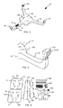
- Fig. 1 shows a production line 1 for the production or production of an article 2 of several components.
- the object 2 is a motor vehicle and the production plant 1 may be a production line for a vehicle, in particular motor vehicle, truck, aircraft, etc.
- the production facility 1 is not limited thereto and may be a production facility for any other industrially manufactured item.
- the production plant 1 in Fig. 1 has a device 10 for handling a load, such as a component of the article 2.
- the component may in particular a body part of the in Fig. 1 be shown as a motor vehicle 2.
- the component may also be a tenter or framer, which is useful for tensioning components of a vehicle in a vehicle body manufacture.
- the production plant 1 in Fig. 1 also has a moving device 20, on which the device 10 is arranged.
- the device 10 is attached to the moving device 20 so that the moving device 20 can move the device 10 in space.
- a load handled by the device 10 is also moved in space.
- the movement device 20 is shown as a robot.
- the moving device 20 can also have any other shape, such as a pivoting arm, a lifting device with a telescopic arm, etc.
- Fig. 2 shows the device 10 in a plan view in more detail.
- the device 10 has a first to third cantilever 11 to 13, a connecting body 14 for connecting the cantilevers 11 to 13 and a coating 15, with which the device 10 is coated on the outside.
- the coating 15 is in Fig. 2 only indicated in more detail at one point.
- a first mounting device 111 is arranged.
- a second mounting device 121 is arranged.
- a third mounting device 131 is arranged, which in Fig. 2 barely visible.
- a handling device for example in the form of a fluidic gripper, in particular a pneumatic gripper, and / or a mechanical gripper, in particular cable gripper, and / or an electric gripper and / or a magnetic coupling is mounted on the mounting device 111, 121, 131, the grippers can to engage and thus handle a load.
- the handling device can also be a tool that is needed in the production in the production plant 1.
- openings 141 are provided in the connecting body 14 which are usable for mounting the device 10 on the moving device 20.
- the assembly of the device 10 on the movement device 20 can also be done by means of automatic docking and undocking.
- Fig. 2 not all openings 141 provided with a reference numeral.
- openings 141 are openings 151 to 156 of the coating 15 provided so that the coating 15 comes close to the openings 141, the openings 141 but exposed.
- the openings 141 are therefore not coated with the coating 15.
- no coupling device is still mounted, with which the device 10 is coupled to the movement device 20.
- Fig. 3 shows the device 10 in a lower view in more detail.
- additional openings 142 are provided at the bottom of the connecting body 14.
- a mounting device 112 in the form of an opening for mounting a tool, a camera, a sensor, another gripper or the like is provided on the side of the first arm 11.
- the in Fig. 3 only indicated coating 15 around the mounting device 112 around provided such that the coating 15 comes close to the mounting device 112, the mounting device 112, however, is exposed and thus not coated with the coating 15.
- Fig. 4 shows a detail of Fig. 3 with the second mounting device 121 in more detail.
- the second mounting device 121, as well as the first and third mounting means 111, 131 are designed such that a handling device, such as a gripper, a tool, a camera or the like can be mounted on it.
- the mounting device 121 has a plurality of openings 121A, with which a handling device, in particular by screws, etc., can be attached.
- the coating 15 consists of a composite of carbon fiber and / or glass fiber and / or basalt fiber with resin.
- the coating 15 is thus a fiber-reinforced plastic.
- the coating 15 is laminated over a framework and thus brings additional strength and also the required rigidity. This is described in more detail below.
- the coating 15 may also consist of continuously endless fiber-reinforced organo-material, in particular organo-sheet. Such includes thermoplastic. Thereby, the continuous fiber-reinforced organo-material can be attached to the skeleton by heating above the melting temperature of the thermoplastic resin and then laminated to the skeleton.
- Another alternative is the spraying of fiber composites, which offer the same properties as the fiber material.
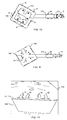
- FIG. 12 illustrates individual parts of a framework from which a part of the apparatus 10 is assembled, as in FIG Fig. 6 to Fig. 11 shown.
- the individual parts 143 to 149 form the individual parts, from which the framework for the connecting body 14 with the openings 141, 142 is assembled.
- the items 146 to 149 is in Fig. 5 for the sake of clarity, only one of the individual parts provided with a reference numeral.
- the items 143 and 144 are spaced apart by the items 146 to 149 by mounting the items 146 to 149 between or on the pieces 143 and 144, respectively.
- the items 146 to 149 may thus also be referred to as spacers.
- the item 145 later serves as a coupling device for coupling the device 10 to the movement device 20.
- the items 122 to 125 form individual parts, from which the framework for the boom 12 is assembled. In Fig.
- FIG. 5 only one item of the items 122 to 125, which are used for the boom 12, is shown.
- tabs 30 are provided, which are in and through through holes 31 of the items 143, 144 pluggable.
- the item 122 also has through holes 31, in and through which tabs 30 of the items 123 to 125 are pluggable.
- a tab 30 and / or a passage opening 31 are hereinafter also referred to as plug-in device 30, 31.
- plug-in device 30 In Fig. 5
- not all lugs 30 and passage openings 31 of the individual parts 143, 144, 122 to 125 are provided with a reference numeral.
- the items 143 to 149 and 122 to 125 may be made of, for example, metal, especially aluminum, iron, etc., plastic, wood, and combinations thereof.
- the items 143, 144 and 122 to 125 may be made in particular of galvanized sheet metal. Other materials are also conceivable which can realize the necessary basic strength or stability for the framework.
- Fig. 6 to Fig. 11 show the device 10, on which a handling device 17 is mounted in the form of a gripper. For the sake of clarity, not all are in Fig. 6 to Fig. 11 Parts provided with a reference numeral.
- the plug-in devices 30, 31 are only partially mounted.
- the tabs 30 of the individual parts 122 to 125 are indeed inserted into the passage opening 31 and inserted through the passage opening 31 up to the edge of the individual parts 143, 144, 122 to 125.
- the tabs 30 are not yet bent over and secured therewith, as in FIG Fig. 12 for the items 143 and 125 shown. So that's the items in Fig. 6 to Fig. 11 not quite attached to each other.
- the tabs 30 are here designed so that they can be easily bent with the thumb of one hand, so without tools. So it's not another tool to assemble of the framework formed from items 143 to 149 and 122 to 125 required.
- At least one of the tabs 30 can have such a material thickness that it can no longer be bent by hand or by the thumb. In such a case, a tool can be used for bending the tabs 30.
- the framework may be provided with the coating 15, as described above and below.
- Fig. 13 shows very schematically a method for producing the device 10.
- a step S1 several individual parts, for example the individual parts 143, 144 and 122 to 125, cut from a planar material, in particular galvanized sheet.
- the cutting can take place with a laser and / or a milling device by means of milling and / or a punching device by means of punching and / or a water jet cutting device by means of water cutting and / or other suitable situational processing, such as spark erosion, electroerosion, etc.
- the passage openings 31 are produced.
- the flow proceeds to a step S2.
- step S2 the items, for example, the items 143 to 149 and 122 to 125 are assembled.
- the individual parts are assembled in such a way that together they form the three-dimensional framework, as in FIG FIG. 6 to FIG. 12 illustrated.
- the assembly can be performed without tools, by interlocking plug-in devices of the items are positively mounted as the three-dimensional framework.
- the mounting devices 111, 121, 131 and possibly also the handling devices 17 are already mounted on the frame at their respective desired position. Thereafter, the flow proceeds to a step S3.
- fiber material is applied around the three-dimensional skeleton fabricated at step S2 to produce the coating 15.
- This may include, for example, coating the three-dimensional framework with a tubular fibrous material.
- individual fibers or fiber mats can also be attached to the framework, in particular laid on top.
- the fiber material may be applied to the framework in one or more layers. It is also possible that the fiber material only at predetermined Sites of the scaffold one or more layers attached. For example, more layers of fiber material may be applied at locations of the scaffold where greater forces will act than at locations of the scaffold where smaller forces will act.
- the fibrous material is applied so as to expose any openings intended to be used to attach the device to the mover 20 or to attach a handling device, etc. Thereafter, the flow proceeds to a step S4.
- step S4 resin is applied to the fiber material attached at step S3.
- the application can be done for example with a brush. It is sufficient that the resin is present between the fibers of the fiber material. Excess resin can be easily scraped off.
- the resin-impregnated fiber material which in the case of a fabric can also be referred to as lamination mats, resembles a wet tissue.
- the step S4 may be omitted, for example, when the fiber material is sprayed with resin as a fiber composite material.
- the step S3 and S4 can also be considered as a common manufacturing step, when the fiber material is applied and applied simultaneously by resin coating. Thereafter, the flow proceeds to a step S5.
- step S5 the resin / fiber composite formed in step S3 is cured as a fiber reinforced plastic and thus the coating 15 of the framework of the device 10 is formed.
- Curing may be either cold or hot cure depending on the type of lamination chosen.
- the construction of the device 10 is given additional strength and rigidity.
- this also avoids re-bending of the tabs 30 protruding through the passage openings 31.
- the skeleton is closed to the outside except for the openings 141, 142, 112, so that foreign matter such as dust, liquid, etc. is prevented from entering. Thereafter, the process is completed.
- a building block module for the device 10 is provided, with which it is possible to create a lightweight cost-effective gripping system in plug-in construction.
- the framework of the device 10 obtains additional strength by the cladding with the fiber material.
- the required rigidity of the device 10 can be ensured.
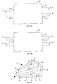
- Fig. 14 shows the item 124 in detail, which item 124 is used for a frame of a device 10 according to a second embodiment.
- the device 10 according to the present embodiment is largely implemented in the same manner as in FIG Referring to the first embodiment described. Therefore, only the differences from the first embodiment will be described below.
- This in Fig. 14 shown item 124 has a centering plug, the in Fig. 14 two tabs 30, two tabs 32 and a web 33 includes.
- the lugs 32 and the ridge 33 each slightly project from the edge of the item 124, as indicated by the dashed lines in FIG Fig. 14 illustrated.
- the two tabs 30 each protrude a lot further from the edge of the item 124 than the tabs 32.
- the tabs 32 and optionally the web 33 so far from the edge of the item 124 cantilever out that they into a through hole 31 of a other item, in this case an item 122, but can not protrude from the through hole 31 when the tabs 30 are bent, as in Fig. 12 shown in the first embodiment.
- the overall width of the tabs 30, the tabs 32 and the web 33 at the edge of the item 124 is slightly smaller than the width of a through hole 31, so that the tabs 30, tabs 32 and the web 33 of the item 124 form a positive connection with the passage opening 31 of the item 122, when mounted thereon in a similar manner as in FIG FIG. 6 to FIG. 12 for the items 123, 125 shown.
- the total width corresponds to the length of one of the dashed lines in Fig. 14 .
- the form-fitting acts as a centering anti-slip device for the interlocking items 122 to 125, 143, 144 and thus also contributes to component stiffness.
- the component rigidity in this case refers both to the scaffold constructed from the individual parts 122 to 125, 143 to 149, and to the device 10 thus completed.
- the other individual parts of the device 10, on which tabs 30 are present, can be designed in the same way as the item 124 with tabs 30 and tabs 32.
- the centering plug comprises no web 33, as in Fig. 15 shown.
- a first modification in this case only one tab 30 is present, on whose sides in each case a nose 32 is arranged, as in Fig. 15 illustrated on the left edge of the item 124.
- two tabs 30 are provided, on whose sides in each case a nose 32 is arranged, as in Fig. 15 illustrated on the right edge of the item 124.
- the edge of the item 124 does not protrude between the tabs 30 but lies, for example, on the same straight line as the edge of the piece Item 124.
- the edge of the item 124 may be notched between the tabs 30 against the other edge of the item 124 from the item 124.
- the centering plug-in device does not comprise lugs 32, as in FIG Fig. 16 shown on the left edge of the item 124.
- only one nose 32 may be present, as in FIG Fig. 16 shown on the right edge of the item 124.
- the positive connection between the individual parts 122 to 125, 143, 144 for the anti-slip device by means of at least the tabs 30 and possibly a nose 32 is formed.
- individual parts 35, 36 of the framework of the device 10 have an edge toothing 37, as in FIG Fig. 17 shown.
- the edges of the individual parts 35, 36 are formed so that they interlock when the individual parts 35, 36 are brought together at their edges.
- the individual parts 35, 36 are assembled with a single part 38 and further non-visible individual parts 35, 36 to form a square profile, in which the item 38 forms a lid arranged in the square profile.
- the item 38 has tabs 30 which are in Fig. 17 are guided through the through holes 31 of the items 35, 36 and bent to the items 35, 36. For clarity in Fig. 17 not all tabs 30 and through holes 31 provided with a reference numeral.
- the items 35, 36, 38 have openings 39 which are in Fig. 17 are also formed as through holes 39, so that the framework is even easier.
- the openings 39 may be designed in particular as a slot or round hole, as in Fig. 17 shown. However, other shapes for the openings 39 are conceivable. Depending on the thickness of the material, the openings 39 can also form a blind hole.
- the bending tabs 30 are not arranged in the edge region of the item 35 in the frame of the individual parts 35, 36, 38 with the edge teeth 37, as described in the previous embodiments, but further arranged on the inside of the item 36. As a result, the framework formed from the individual parts 35, 36 and an individual part 38 becomes even more stable.
- the edge gearing can be used in the method that is related to Fig. 13 is prepared at step S1 by cutting or removing the desired notches on the individual parts 35, 36 prepared.
- the shape of the device 10 is arbitrary.
- the number of arms 11, 12, 13 can be freely selected.
- only a boom or no boom is possible.
- the number of connecting body 14 is arbitrary. The same applies to the shape of the arms 11, 12, 13 and the connecting body 14.
- edges of the individual parts are preferably rounded. Preference is given to constructions which do not have sharp-edged shapes. This favors the lamination with the fiber material.
- the fiber material can be applied to the component 125 filler of lightweight materials, such as cardboard, felt, etc., to the between the components 125, 143 in Fig. 12 compensate offset shown. As a result, the bending radius of the fibers of the fiber material can be optimized.
- one or more individual parts of the framework of the device 10 consist of a tubular material.
- planar items are usually easier and / or cheaper moldable, transportable and processable, planar items are preferred.
- the plug-in device can also be designed as a snaphaken and / or Sch noirspriegel instead of a tab 30.
- the through hole 31 is to be formed, in which the snaphaks and / or Sch noirspriegel, etc. to intervene. It is also a combination of tab 30 and Snaphaken or a combination of tab 30 and Sch noirspriegel possible.
- flap 30, Snaphaken and welding bow for a plug-in device can be combined.
- more than one tab 30 and / or snaphaken and / or Sch noirspriegel can be used for a plug-in device.
- the steps S1 and / or S2 of the method can also be carried out by a manufacturer other than the manufacturer who produces the coating 15 by means of the steps S3 to S5.
- a modular system with the items according to Fig. 5 be supplied, so that a manufacturer of the device 10 only needs to perform steps S2 to S5.
- the fiber is aligned in the direction of the expected load to optimally absorb the forces.
- the coating 15 closes the framework to the outside with the exception of the openings 141, 142, 112, this is not absolutely necessary.
- the coating 15 and thus the fiber material for the coating 15 to be applied only to one side of the framework.
Claims (15)
- Dispositif (10) à utiliser dans la manipulation d'une charge, le dispositif comprenant
un échafaudage tridimensionnel qui comprend de multiples composants individuels (143 à 149, 122 à 125; 35, 36, 38), dans lequel au moins une partie des composants individuels (143 à 149, 122 à 125; 35, 36, 38) sont des éléments plans qui comprennent au moins un moyen formant bouchon (30, 31) avec lequel les composants individuels (143, 144, 122 à 125; 35, 36, 38) peuvent être assemblés en tant que l'échafaudage tridimensionnel,
un revêtement (15) constitué de plastique renforcé de fibres avec lequel l'échafaudage est revêtu, et
au moins un moyen de montage (111, 121, 131) pour un moyen de manipulation (17) permettant de manipuler une partie qui est utilisable dans la production d'un objet(2) et qui forme la charge. - Dispositif (10) selon la revendication 1, dans lequel les multiples composants individuels (143, 144, 122 à 125; 35, 36, 38) sont des éléments plans qui comprennent au moins un moyen formant bouchon (30, 31) avec lequel les composants individuels (143, 144, 122 à 125; 35, 36, 38) peuvent être assemblés en tant que l'échafaudage tridimensionnel.
- Dispositif (10) selon la revendication 1 ou 2, dans lequel les composants individuels (143, 144, 122 à 125; 35, 36, 38) sont des éléments plans qui comprennent des moyens formant bouchon de verrouillage (30, 31) de sorte que les composants individuels (143, 144, 122 à 125; 35, 36, 38) puissent être montés par complémentarité de forme en tant que l'échafaudage tridimensionnel.
- Dispositif (10) selon la revendication 2 ou 3, dans lequel les composants individuels (143, 144, 122 à 125; 35, 36, 38) comprennent au moins un moyen formant bouchon (30, 31) qui est configuré comme une lanière (30, 31) ou une ouverture traversante (31), dans lequel le moyen formant bouchon (30, 31) est configuré de telle sorte que la lanière (30) d'un composant individuel (125; 38) puisse être bouchée dans une ouverture traversante (31) d'un autre composant individuel (143; 35, 36) et, par la suite, puisse être assujetti à l'autre composant individuel (143; 35, 36), sans avoir besoin d'outils.
- Dispositif (10) selon l'une des revendications précédentes, dans lequel des composants individuels (35, 36) de l'échafaudage du dispositif (10) comprennent une indentation de bord (37).
- Dispositif (10) selon l'une des revendications précédentes, dans lequel l'échafaudage comprend au moins un porte-à-faux (11, 12, 13) à l'extrémité duquel est positionné un moyen de manipulation mécanique ou fluidique (17) au niveau de l'un du au moins un moyen de montage (111, 121, 131).
- Dispositif (10) selon l'une des revendications précédentes, dans lequel le dispositif comprend de multiples moyens de manipulation qui coopèrent pour manipuler une partie utilisable dans la production de l'objet.
- Dispositif (10) selon l'une des revendications précédentes, dans lequel le plastique renforcé de fibres comprend un organomatériau renforcé de fibres de carbone et/ou de fibres de verre et/ou de fibres de basalte et/ou de filaments continus.
- Dispositif (10) selon l'une des revendications précédentes, dans lequel le dispositif sert à manipuler des composants de construction pour produire un véhicule et/ou de cadres de bridage permettant de brider des composants de construction d'un véhicule dans la production de la carrosserie d'un véhicule, et/ou comprend un moyen de couplage permettant de coupler le dispositif à un dispositif de déplacement permettant de déplacer le dispositif dans l'espace.
- Installation de production (1) permettant de produire un objet (2), comprenant
un dispositif (10) selon l'une des revendications précédentes,
au moins un moyen de manipulation (17) qui est monté sur l'un du au moins un moyen de montage (111, 121, 131), et
un dispositif de déplacement (20) permettant de déplacer le dispositif (10) dans l'espace. - Procédé de production d'un dispositif (10) à utiliser dans la manipulation d'une charge, le procédé comprenant les étapes
d'assemblage (S2) de composants individuels (143 149, 122 à 125; 35, 36, 38) de sorte qu'ils forment ensemble un échafaudage tridimensionnel au niveau duquel est prévu au moins un moyen de montage (111, 121, 131) pour un moyen de manipulation (17) permettant de manipuler une partie qui est utilisable dans la production d'un objet (2) et qui est prévu en tant que la charge, dans lequel au moins une partie des composants individuels (143 à 149, 122 à 125, 35, 36, 38) sont des éléments plans qui comprennent au moins un moyen formant bouchon (30, 31) avec lequel les composants individuels (143 à 149, 122 à 125, 35, 36, 38) sont assemblés en tant que l'échafaudage tridimensionnel,
de fixation (S3) d'un matériau de fibres autour de l'échafaudage tridimensionnel,
d'application (S4) d'une résine au matériau de fibres et,
de durcissement (S5) du composite résine/matériau de fibres en tant que plastique renforcé de fibres en tant que revêtement (15) de l'échafaudage. - Procédé selon la revendication 11, dans lequel l'étape d'assemblage (S2) est exécutée sans outil et dans laquelle étape des moyens formant bouchon de verrouillage (30, 31) des composants individuels (143, 144, 122 à 125, 35, 36, 38) sont montés par liaison de forme en tant que l'échafaudage tridimensionnel.
- Procédé selon la revendication 11 ou 12, comprenant en outre une étape de découpe (S1), avec un laser et/ou un moyen de fraisage et/ou un moyen de poinçon et/ou un moyen de découpe au jet d'eau, de multiples composants individuels à partir d'un matériau de base plan.
- Procédé selon l'une des revendications 11 à 13, dans lequel l'étape de fixation (S3) de matériau de fibres comprend le recouvrement de l'échafaudage tridimensionnel avec un matériau de fibres tubulaire.
- Procédé selon l'une des revendications 11 à 14, dans lequel l'étape de fixation (S3) de matériau de fibres est exécutée de sorte que les ouvertures (141, 142, 112) soient autonomes, lesquelles servent à fixer le dispositif (10) à un dispositif de déplacement (20) permettant de déplacer le dispositif (10) dans l'espace.
Priority Applications (8)
| Application Number | Priority Date | Filing Date | Title |
|---|---|---|---|
| ES13171149.1T ES2541428T3 (es) | 2013-06-07 | 2013-06-07 | Dispositivo para su uso en la manipulación de una carga y procedimiento para fabricar un dispositivo de este tipo |
| EP13171149.1A EP2810749B1 (fr) | 2013-06-07 | 2013-06-07 | Dispositif pour l'utilisation lors de la manipulation d'une charge et procédé de fabrication d'un tel dispositif |
| PCT/EP2014/061541 WO2014195340A1 (fr) | 2013-06-07 | 2014-06-04 | Dispositif destiné à être utilisé pour la manutention d'une charge et procédé de fabrication dudit dispositif |
| KR1020167000087A KR101820608B1 (ko) | 2013-06-07 | 2014-06-04 | 적재물을 조작하는데 이용하기 위한 디바이스 및 이러한 디바이스를 제조하기 위한 방법 |
| JP2016517281A JP6084337B2 (ja) | 2013-06-07 | 2014-06-04 | 重量物ハンドリング用デバイス、及びそのようなデバイスの製作方法 |
| US14/896,565 US10173327B2 (en) | 2013-06-07 | 2014-06-04 | Device for use in the handling of a load and method for producing such a device |
| ATA9198/2014A AT520371B1 (de) | 2013-06-07 | 2014-06-04 | Vorrichtung zur Verwendung beim Handhaben einer Last und Verfahren zum Herstellen einer derartigen Vorrichtung |
| CN201480031452.4A CN105492171B (zh) | 2013-06-07 | 2014-06-04 | 用于操纵负载的装置以及这种装置的生产方法 |
Applications Claiming Priority (1)
| Application Number | Priority Date | Filing Date | Title |
|---|---|---|---|
| EP13171149.1A EP2810749B1 (fr) | 2013-06-07 | 2013-06-07 | Dispositif pour l'utilisation lors de la manipulation d'une charge et procédé de fabrication d'un tel dispositif |
Publications (2)
| Publication Number | Publication Date |
|---|---|
| EP2810749A1 EP2810749A1 (fr) | 2014-12-10 |
| EP2810749B1 true EP2810749B1 (fr) | 2015-04-29 |
Family
ID=48607115
Family Applications (1)
| Application Number | Title | Priority Date | Filing Date |
|---|---|---|---|
| EP13171149.1A Active EP2810749B1 (fr) | 2013-06-07 | 2013-06-07 | Dispositif pour l'utilisation lors de la manipulation d'une charge et procédé de fabrication d'un tel dispositif |
Country Status (8)
| Country | Link |
|---|---|
| US (1) | US10173327B2 (fr) |
| EP (1) | EP2810749B1 (fr) |
| JP (1) | JP6084337B2 (fr) |
| KR (1) | KR101820608B1 (fr) |
| CN (1) | CN105492171B (fr) |
| AT (1) | AT520371B1 (fr) |
| ES (1) | ES2541428T3 (fr) |
| WO (1) | WO2014195340A1 (fr) |
Families Citing this family (78)
| Publication number | Priority date | Publication date | Assignee | Title |
|---|---|---|---|---|
| KR20170019366A (ko) | 2014-05-16 | 2017-02-21 | 디버전트 테크놀로지스, 인크. | 차량 섀시용 모듈형 성형 접속체 및 그 사용 방법 |
| SG10201806531QA (en) | 2014-07-02 | 2018-09-27 | Divergent Technologies Inc | Systems and methods for fabricating joint members |
| CN106794909B (zh) * | 2014-08-05 | 2019-04-09 | 康宁股份有限公司 | 臂端工具 |
| JP2019527138A (ja) | 2016-06-09 | 2019-09-26 | ダイバージェント テクノロジーズ, インコーポレイテッドDivergent Technologies, Inc. | アークおよびノードの設計ならびに製作のためのシステムおよび方法 |
| US11155005B2 (en) | 2017-02-10 | 2021-10-26 | Divergent Technologies, Inc. | 3D-printed tooling and methods for producing same |
| US10759090B2 (en) | 2017-02-10 | 2020-09-01 | Divergent Technologies, Inc. | Methods for producing panels using 3D-printed tooling shells |
| US10898968B2 (en) | 2017-04-28 | 2021-01-26 | Divergent Technologies, Inc. | Scatter reduction in additive manufacturing |
| US10703419B2 (en) | 2017-05-19 | 2020-07-07 | Divergent Technologies, Inc. | Apparatus and methods for joining panels |
| US11358337B2 (en) | 2017-05-24 | 2022-06-14 | Divergent Technologies, Inc. | Robotic assembly of transport structures using on-site additive manufacturing |
| US11123973B2 (en) | 2017-06-07 | 2021-09-21 | Divergent Technologies, Inc. | Interconnected deflectable panel and node |
| US10919230B2 (en) | 2017-06-09 | 2021-02-16 | Divergent Technologies, Inc. | Node with co-printed interconnect and methods for producing same |
| US10781846B2 (en) | 2017-06-19 | 2020-09-22 | Divergent Technologies, Inc. | 3-D-printed components including fasteners and methods for producing same |
| US10994876B2 (en) | 2017-06-30 | 2021-05-04 | Divergent Technologies, Inc. | Automated wrapping of components in transport structures |
| US11022375B2 (en) | 2017-07-06 | 2021-06-01 | Divergent Technologies, Inc. | Apparatus and methods for additively manufacturing microtube heat exchangers |
| US10895315B2 (en) | 2017-07-07 | 2021-01-19 | Divergent Technologies, Inc. | Systems and methods for implementing node to node connections in mechanized assemblies |
| US10940609B2 (en) | 2017-07-25 | 2021-03-09 | Divergent Technologies, Inc. | Methods and apparatus for additively manufactured endoskeleton-based transport structures |
| US10751800B2 (en) | 2017-07-25 | 2020-08-25 | Divergent Technologies, Inc. | Methods and apparatus for additively manufactured exoskeleton-based transport structures |
| US10605285B2 (en) | 2017-08-08 | 2020-03-31 | Divergent Technologies, Inc. | Systems and methods for joining node and tube structures |
| US10357959B2 (en) | 2017-08-15 | 2019-07-23 | Divergent Technologies, Inc. | Methods and apparatus for additively manufactured identification features |
| DE102017119489A1 (de) * | 2017-08-25 | 2019-02-28 | Kuka Systems Gmbh | Positionier- und Spannsystem und Verfahren |
| US11306751B2 (en) | 2017-08-31 | 2022-04-19 | Divergent Technologies, Inc. | Apparatus and methods for connecting tubes in transport structures |
| US10960611B2 (en) | 2017-09-06 | 2021-03-30 | Divergent Technologies, Inc. | Methods and apparatuses for universal interface between parts in transport structures |
| US11292058B2 (en) | 2017-09-12 | 2022-04-05 | Divergent Technologies, Inc. | Apparatus and methods for optimization of powder removal features in additively manufactured components |
| US10814564B2 (en) | 2017-10-11 | 2020-10-27 | Divergent Technologies, Inc. | Composite material inlay in additively manufactured structures |
| US10668816B2 (en) | 2017-10-11 | 2020-06-02 | Divergent Technologies, Inc. | Solar extended range electric vehicle with panel deployment and emitter tracking |
| US11786971B2 (en) | 2017-11-10 | 2023-10-17 | Divergent Technologies, Inc. | Structures and methods for high volume production of complex structures using interface nodes |
| US10926599B2 (en) | 2017-12-01 | 2021-02-23 | Divergent Technologies, Inc. | Suspension systems using hydraulic dampers |
| CN108032277A (zh) * | 2017-12-04 | 2018-05-15 | 深圳市今天国际智能机器人有限公司 | 带有升降机构的机器人 |
| US11110514B2 (en) | 2017-12-14 | 2021-09-07 | Divergent Technologies, Inc. | Apparatus and methods for connecting nodes to tubes in transport structures |
| US11085473B2 (en) | 2017-12-22 | 2021-08-10 | Divergent Technologies, Inc. | Methods and apparatus for forming node to panel joints |
| US11534828B2 (en) | 2017-12-27 | 2022-12-27 | Divergent Technologies, Inc. | Assembling structures comprising 3D printed components and standardized components utilizing adhesive circuits |
| US11420262B2 (en) | 2018-01-31 | 2022-08-23 | Divergent Technologies, Inc. | Systems and methods for co-casting of additively manufactured interface nodes |
| US10751934B2 (en) | 2018-02-01 | 2020-08-25 | Divergent Technologies, Inc. | Apparatus and methods for additive manufacturing with variable extruder profiles |
| US11224943B2 (en) | 2018-03-07 | 2022-01-18 | Divergent Technologies, Inc. | Variable beam geometry laser-based powder bed fusion |
| US11267236B2 (en) | 2018-03-16 | 2022-03-08 | Divergent Technologies, Inc. | Single shear joint for node-to-node connections |
| US11872689B2 (en) | 2018-03-19 | 2024-01-16 | Divergent Technologies, Inc. | End effector features for additively manufactured components |
| US11254381B2 (en) | 2018-03-19 | 2022-02-22 | Divergent Technologies, Inc. | Manufacturing cell based vehicle manufacturing system and method |
| US11408216B2 (en) | 2018-03-20 | 2022-08-09 | Divergent Technologies, Inc. | Systems and methods for co-printed or concurrently assembled hinge structures |
| US11613078B2 (en) | 2018-04-20 | 2023-03-28 | Divergent Technologies, Inc. | Apparatus and methods for additively manufacturing adhesive inlet and outlet ports |
| US11214317B2 (en) | 2018-04-24 | 2022-01-04 | Divergent Technologies, Inc. | Systems and methods for joining nodes and other structures |
| US11020800B2 (en) | 2018-05-01 | 2021-06-01 | Divergent Technologies, Inc. | Apparatus and methods for sealing powder holes in additively manufactured parts |
| US10682821B2 (en) | 2018-05-01 | 2020-06-16 | Divergent Technologies, Inc. | Flexible tooling system and method for manufacturing of composite structures |
| US11389816B2 (en) | 2018-05-09 | 2022-07-19 | Divergent Technologies, Inc. | Multi-circuit single port design in additively manufactured node |
| US10691104B2 (en) | 2018-05-16 | 2020-06-23 | Divergent Technologies, Inc. | Additively manufacturing structures for increased spray forming resolution or increased fatigue life |
| US11590727B2 (en) | 2018-05-21 | 2023-02-28 | Divergent Technologies, Inc. | Custom additively manufactured core structures |
| US11441586B2 (en) | 2018-05-25 | 2022-09-13 | Divergent Technologies, Inc. | Apparatus for injecting fluids in node based connections |
| US11035511B2 (en) | 2018-06-05 | 2021-06-15 | Divergent Technologies, Inc. | Quick-change end effector |
| CN108748122A (zh) * | 2018-06-29 | 2018-11-06 | 平湖市浩鑫塑胶有限公司 | 一种塑料瓶的夹持移动机构 |
| US11292056B2 (en) | 2018-07-06 | 2022-04-05 | Divergent Technologies, Inc. | Cold-spray nozzle |
| US11269311B2 (en) | 2018-07-26 | 2022-03-08 | Divergent Technologies, Inc. | Spray forming structural joints |
| US10836120B2 (en) | 2018-08-27 | 2020-11-17 | Divergent Technologies, Inc . | Hybrid composite structures with integrated 3-D printed elements |
| US11433557B2 (en) | 2018-08-28 | 2022-09-06 | Divergent Technologies, Inc. | Buffer block apparatuses and supporting apparatuses |
| US11826953B2 (en) | 2018-09-12 | 2023-11-28 | Divergent Technologies, Inc. | Surrogate supports in additive manufacturing |
| US11072371B2 (en) | 2018-10-05 | 2021-07-27 | Divergent Technologies, Inc. | Apparatus and methods for additively manufactured structures with augmented energy absorption properties |
| US11260582B2 (en) | 2018-10-16 | 2022-03-01 | Divergent Technologies, Inc. | Methods and apparatus for manufacturing optimized panels and other composite structures |
| US11504912B2 (en) | 2018-11-20 | 2022-11-22 | Divergent Technologies, Inc. | Selective end effector modular attachment device |
| USD911222S1 (en) | 2018-11-21 | 2021-02-23 | Divergent Technologies, Inc. | Vehicle and/or replica |
| US11449021B2 (en) | 2018-12-17 | 2022-09-20 | Divergent Technologies, Inc. | Systems and methods for high accuracy fixtureless assembly |
| US11529741B2 (en) | 2018-12-17 | 2022-12-20 | Divergent Technologies, Inc. | System and method for positioning one or more robotic apparatuses |
| US10663110B1 (en) | 2018-12-17 | 2020-05-26 | Divergent Technologies, Inc. | Metrology apparatus to facilitate capture of metrology data |
| US11885000B2 (en) | 2018-12-21 | 2024-01-30 | Divergent Technologies, Inc. | In situ thermal treatment for PBF systems |
| CN111573559B (zh) * | 2019-02-15 | 2021-08-03 | 沈阳新松机器人自动化股份有限公司 | 一种机器人端拾器 |
| US11203240B2 (en) | 2019-04-19 | 2021-12-21 | Divergent Technologies, Inc. | Wishbone style control arm assemblies and methods for producing same |
| DE202019105343U1 (de) | 2019-09-26 | 2019-10-21 | Fft Produktionssysteme Gmbh & Co. Kg | Antriebssystem für eine Vorrichtung zur Verwendung beim Handhaben einer Last |
| US11912339B2 (en) | 2020-01-10 | 2024-02-27 | Divergent Technologies, Inc. | 3-D printed chassis structure with self-supporting ribs |
| US11590703B2 (en) | 2020-01-24 | 2023-02-28 | Divergent Technologies, Inc. | Infrared radiation sensing and beam control in electron beam additive manufacturing |
| US11884025B2 (en) | 2020-02-14 | 2024-01-30 | Divergent Technologies, Inc. | Three-dimensional printer and methods for assembling parts via integration of additive and conventional manufacturing operations |
| US11479015B2 (en) | 2020-02-14 | 2022-10-25 | Divergent Technologies, Inc. | Custom formed panels for transport structures and methods for assembling same |
| US11421577B2 (en) | 2020-02-25 | 2022-08-23 | Divergent Technologies, Inc. | Exhaust headers with integrated heat shielding and thermal syphoning |
| US11535322B2 (en) | 2020-02-25 | 2022-12-27 | Divergent Technologies, Inc. | Omni-positional adhesion device |
| US11413686B2 (en) | 2020-03-06 | 2022-08-16 | Divergent Technologies, Inc. | Methods and apparatuses for sealing mechanisms for realizing adhesive connections with additively manufactured components |
| US11850804B2 (en) | 2020-07-28 | 2023-12-26 | Divergent Technologies, Inc. | Radiation-enabled retention features for fixtureless assembly of node-based structures |
| US11806941B2 (en) | 2020-08-21 | 2023-11-07 | Divergent Technologies, Inc. | Mechanical part retention features for additively manufactured structures |
| US11872626B2 (en) | 2020-12-24 | 2024-01-16 | Divergent Technologies, Inc. | Systems and methods for floating pin joint design |
| US11947335B2 (en) | 2020-12-30 | 2024-04-02 | Divergent Technologies, Inc. | Multi-component structure optimization for combining 3-D printed and commercially available parts |
| US11928966B2 (en) | 2021-01-13 | 2024-03-12 | Divergent Technologies, Inc. | Virtual railroad |
| EP4304865A1 (fr) | 2021-03-09 | 2024-01-17 | Divergent Technologies, Inc. | Systèmes et procédés de fabrication additive rotative |
| US11865617B2 (en) | 2021-08-25 | 2024-01-09 | Divergent Technologies, Inc. | Methods and apparatuses for wide-spectrum consumption of output of atomization processes across multi-process and multi-scale additive manufacturing modalities |
Family Cites Families (11)
| Publication number | Priority date | Publication date | Assignee | Title |
|---|---|---|---|---|
| US3098287A (en) * | 1958-07-22 | 1963-07-23 | Hazeltine Research Inc | Method of assembling components on printed wiring boards |
| CN2222688Y (zh) | 1995-06-30 | 1996-03-20 | 朱占新 | 一种拼装式包装箱 |
| CN100402246C (zh) * | 2001-03-29 | 2008-07-16 | 日石三菱株式会社 | 机器人手部件及其制造方法 |
| US7300082B2 (en) * | 2003-07-21 | 2007-11-27 | Asyst Technologies, Inc. | Active edge gripping and effector |
| JP4980712B2 (ja) * | 2004-04-20 | 2012-07-18 | Jx日鉱日石エネルギー株式会社 | ロボットハンド部材、その製造方法及びロボットハンド |
| US8108978B2 (en) * | 2005-07-06 | 2012-02-07 | Norgren Automation Solutions, Inc. | Apparatus for accurately positioning and supporting modular tooling |
| SE532109C2 (sv) | 2008-01-17 | 2009-10-27 | Flexprop Ab | Hållare för positionering och lägesfixering av arbetsstycke och förfarande för dess tillverkning |
| JP4883017B2 (ja) * | 2008-01-24 | 2012-02-22 | 株式会社安川電機 | 基板把持装置およびそれを備えた基板搬送ロボット、半導体製造装置 |
| US20090297319A1 (en) * | 2008-06-02 | 2009-12-03 | Kalb James R | Composite for automated handling device |
| EP2465651A1 (fr) | 2010-12-14 | 2012-06-20 | FFT EDAG Produktionssysteme GmbH & Co. KG | Dispositif de réception et de manipulation d'un composant et procédé de fabrication d'un tel dispositif |
| DE202012102102U1 (de) * | 2012-06-08 | 2012-07-03 | De-Sta-Co Europe Gmbh | Verbindungselement |
-
2013
- 2013-06-07 ES ES13171149.1T patent/ES2541428T3/es active Active
- 2013-06-07 EP EP13171149.1A patent/EP2810749B1/fr active Active
-
2014
- 2014-06-04 WO PCT/EP2014/061541 patent/WO2014195340A1/fr active Application Filing
- 2014-06-04 US US14/896,565 patent/US10173327B2/en active Active
- 2014-06-04 JP JP2016517281A patent/JP6084337B2/ja active Active
- 2014-06-04 CN CN201480031452.4A patent/CN105492171B/zh active Active
- 2014-06-04 AT ATA9198/2014A patent/AT520371B1/de active IP Right Revival
- 2014-06-04 KR KR1020167000087A patent/KR101820608B1/ko active IP Right Grant
Also Published As
| Publication number | Publication date |
|---|---|
| US20160121488A1 (en) | 2016-05-05 |
| CN105492171B (zh) | 2018-11-02 |
| US10173327B2 (en) | 2019-01-08 |
| AT520371A5 (de) | 2019-03-15 |
| EP2810749A1 (fr) | 2014-12-10 |
| WO2014195340A1 (fr) | 2014-12-11 |
| JP6084337B2 (ja) | 2017-02-22 |
| CN105492171A (zh) | 2016-04-13 |
| AT520371B1 (de) | 2019-06-15 |
| ES2541428T3 (es) | 2015-07-20 |
| KR101820608B1 (ko) | 2018-02-28 |
| KR20160015364A (ko) | 2016-02-12 |
| JP2016520442A (ja) | 2016-07-14 |
Similar Documents
| Publication | Publication Date | Title |
|---|---|---|
| EP2810749B1 (fr) | Dispositif pour l'utilisation lors de la manipulation d'une charge et procédé de fabrication d'un tel dispositif | |
| DE69911507T2 (de) | Flügelstruktur aus Faserverbundstoff | |
| DE102006035939B4 (de) | Verfahren zur Herstellung von Faserverbundbauteilen und Faserverbundbauteil | |
| DE102006022279B4 (de) | Rotorblatt für eine Windenergieanlage | |
| DE10145991B4 (de) | Rahmen für ein batteriebetriebenes Flurförderzeug | |
| EP3180243B1 (fr) | Élément de gouverne pour aéronef | |
| EP2039487A1 (fr) | Composant à structure fibreuse, composant de robot, robot industriel, composant composite général, composants composites pour véhicules terrestres, spatiaux et aéronefs et procédé de fabrication d'un composant à structure fibreuse | |
| AT512563B1 (de) | Faserwerkstoffrohling sowie Verfahren zur Herstellung eines Faserwerkstoffverbundbauteils | |
| WO2015040050A1 (fr) | Procédé d'enroulement d'éléments composites renforcés de fibres | |
| DE19806484A1 (de) | Verbundteil und Verfahren zu dessen Herstellung | |
| EP0108870A1 (fr) | Corps porteur de pare-chocs en matière renforcée de fibres pour automobiles ou équivalents | |
| EP2643143B1 (fr) | Dispositif de fabrication modulaire de demi-produits en fibres réalisés d'une seule pièce et procédé de fabrication, à partir desdits demi-produits, d'éléments composites en fibres continues comportant une structure à corps creux | |
| DE102016103484A1 (de) | Faserlegekopf zum Legen von Faserhalbzeugprofilen, Faserlegeanlage sowie Verfahren hierzu | |
| EP3543430A1 (fr) | Appareil de positionnement et procédé de fabrication d'un élément de construction renforcé | |
| DE102008023208A1 (de) | Bauteil in Hybridbauweise | |
| DE102015104393B4 (de) | Faserlegekopf und Faserlegevorrichtung mit diesbezüglichem Faserlegekopf | |
| DE102017115442A1 (de) | Industrieroboter und Verfahren zur Herstellung eines Industrieroboters | |
| EP2524861B1 (fr) | Dispositif et procédé de manipulation d'un support d'outil de montage de véhicule sur une ligne de fabrication de véhicule, support d'outil de montage de véhicule et station de montage | |
| DE102019005478A1 (de) | Werkzeug für eine Handhabungseinrichtung sowie Verfahren zur Herstellung eines Werkzeuges für eine Handhabungseinrichtung | |
| EP2465651A1 (fr) | Dispositif de réception et de manipulation d'un composant et procédé de fabrication d'un tel dispositif | |
| DE19826246A1 (de) | Teilesatz zum Aufbau einer Konsole sowie Verfahren zum Herstellen einer Konsole und zum Ausstellen einer Maschine | |
| DE102013223302A1 (de) | Verfahren zur Reparatur von Composite-verstärkten metallischen Strukturen in Hybridbauweise | |
| DE102012222384A1 (de) | Greifer, Greifsystem sowie Einbauverfahren für Fahrzeugsitze | |
| DE102016003442A1 (de) | Verfahren zum Herstellen eines faserverstärkten Bauteils und faserverstärktes Bauteil | |
| WO2017012756A1 (fr) | Système de portique à haute vitesse avec entraînement linéaire |
Legal Events
| Date | Code | Title | Description |
|---|---|---|---|
| PUAI | Public reference made under article 153(3) epc to a published international application that has entered the european phase |
Free format text: ORIGINAL CODE: 0009012 |
|
| 17P | Request for examination filed |
Effective date: 20140730 |
|
| AK | Designated contracting states |
Kind code of ref document: A1 Designated state(s): AL AT BE BG CH CY CZ DE DK EE ES FI FR GB GR HR HU IE IS IT LI LT LU LV MC MK MT NL NO PL PT RO RS SE SI SK SM TR |
|
| AX | Request for extension of the european patent |
Extension state: BA ME |
|
| GRAP | Despatch of communication of intention to grant a patent |
Free format text: ORIGINAL CODE: EPIDOSNIGR1 |
|
| INTG | Intention to grant announced |
Effective date: 20150204 |
|
| GRAS | Grant fee paid |
Free format text: ORIGINAL CODE: EPIDOSNIGR3 |
|
| GRAA | (expected) grant |
Free format text: ORIGINAL CODE: 0009210 |
|
| RBV | Designated contracting states (corrected) |
Designated state(s): AL AT BE BG CH CY CZ DE DK EE ES FI FR GB GR HR HU IE IS IT LI LT LU LV MC MK MT NL NO PL PT RO RS SE SI SK SM TR |
|
| AK | Designated contracting states |
Kind code of ref document: B1 Designated state(s): AL AT BE BG CH CY CZ DE DK EE ES FI FR GB GR HR HU IE IS IT LI LT LU LV MC MK MT NL NO PL PT RO RS SE SI SK SM TR |
|
| REG | Reference to a national code |
Ref country code: GB Ref legal event code: FG4D Free format text: NOT ENGLISH |
|
| REG | Reference to a national code |
Ref country code: CH Ref legal event code: EP |
|
| REG | Reference to a national code |
Ref country code: AT Ref legal event code: REF Ref document number: 724176 Country of ref document: AT Kind code of ref document: T Effective date: 20150515 |
|
| REG | Reference to a national code |
Ref country code: IE Ref legal event code: FG4D Free format text: LANGUAGE OF EP DOCUMENT: GERMAN |
|
| REG | Reference to a national code |
Ref country code: DE Ref legal event code: R096 Ref document number: 502013000597 Country of ref document: DE Effective date: 20150611 |
|
| REG | Reference to a national code |
Ref country code: RO Ref legal event code: EPE |
|
| REG | Reference to a national code |
Ref country code: FR Ref legal event code: PLFP Year of fee payment: 3 |
|
| REG | Reference to a national code |
Ref country code: ES Ref legal event code: FG2A Ref document number: 2541428 Country of ref document: ES Kind code of ref document: T3 Effective date: 20150720 |
|
| REG | Reference to a national code |
Ref country code: SE Ref legal event code: TRGR |
|
| REG | Reference to a national code |
Ref country code: NL Ref legal event code: VDEP Effective date: 20150429 |
|
| REG | Reference to a national code |
Ref country code: LT Ref legal event code: MG4D |
|
| PG25 | Lapsed in a contracting state [announced via postgrant information from national office to epo] |
Ref country code: NL Free format text: LAPSE BECAUSE OF FAILURE TO SUBMIT A TRANSLATION OF THE DESCRIPTION OR TO PAY THE FEE WITHIN THE PRESCRIBED TIME-LIMIT Effective date: 20150429 |
|
| PG25 | Lapsed in a contracting state [announced via postgrant information from national office to epo] |
Ref country code: HR Free format text: LAPSE BECAUSE OF FAILURE TO SUBMIT A TRANSLATION OF THE DESCRIPTION OR TO PAY THE FEE WITHIN THE PRESCRIBED TIME-LIMIT Effective date: 20150429 Ref country code: PT Free format text: LAPSE BECAUSE OF FAILURE TO SUBMIT A TRANSLATION OF THE DESCRIPTION OR TO PAY THE FEE WITHIN THE PRESCRIBED TIME-LIMIT Effective date: 20150831 Ref country code: FI Free format text: LAPSE BECAUSE OF FAILURE TO SUBMIT A TRANSLATION OF THE DESCRIPTION OR TO PAY THE FEE WITHIN THE PRESCRIBED TIME-LIMIT Effective date: 20150429 Ref country code: NO Free format text: LAPSE BECAUSE OF FAILURE TO SUBMIT A TRANSLATION OF THE DESCRIPTION OR TO PAY THE FEE WITHIN THE PRESCRIBED TIME-LIMIT Effective date: 20150729 Ref country code: LT Free format text: LAPSE BECAUSE OF FAILURE TO SUBMIT A TRANSLATION OF THE DESCRIPTION OR TO PAY THE FEE WITHIN THE PRESCRIBED TIME-LIMIT Effective date: 20150429 |
|
| PG25 | Lapsed in a contracting state [announced via postgrant information from national office to epo] |
Ref country code: RS Free format text: LAPSE BECAUSE OF FAILURE TO SUBMIT A TRANSLATION OF THE DESCRIPTION OR TO PAY THE FEE WITHIN THE PRESCRIBED TIME-LIMIT Effective date: 20150429 Ref country code: LV Free format text: LAPSE BECAUSE OF FAILURE TO SUBMIT A TRANSLATION OF THE DESCRIPTION OR TO PAY THE FEE WITHIN THE PRESCRIBED TIME-LIMIT Effective date: 20150429 Ref country code: IS Free format text: LAPSE BECAUSE OF FAILURE TO SUBMIT A TRANSLATION OF THE DESCRIPTION OR TO PAY THE FEE WITHIN THE PRESCRIBED TIME-LIMIT Effective date: 20150829 Ref country code: GR Free format text: LAPSE BECAUSE OF FAILURE TO SUBMIT A TRANSLATION OF THE DESCRIPTION OR TO PAY THE FEE WITHIN THE PRESCRIBED TIME-LIMIT Effective date: 20150730 |
|
| PG25 | Lapsed in a contracting state [announced via postgrant information from national office to epo] |
Ref country code: DK Free format text: LAPSE BECAUSE OF FAILURE TO SUBMIT A TRANSLATION OF THE DESCRIPTION OR TO PAY THE FEE WITHIN THE PRESCRIBED TIME-LIMIT Effective date: 20150429 Ref country code: EE Free format text: LAPSE BECAUSE OF FAILURE TO SUBMIT A TRANSLATION OF THE DESCRIPTION OR TO PAY THE FEE WITHIN THE PRESCRIBED TIME-LIMIT Effective date: 20150429 Ref country code: MC Free format text: LAPSE BECAUSE OF FAILURE TO SUBMIT A TRANSLATION OF THE DESCRIPTION OR TO PAY THE FEE WITHIN THE PRESCRIBED TIME-LIMIT Effective date: 20150429 |
|
| REG | Reference to a national code |
Ref country code: DE Ref legal event code: R097 Ref document number: 502013000597 Country of ref document: DE |
|
| PG25 | Lapsed in a contracting state [announced via postgrant information from national office to epo] |
Ref country code: PL Free format text: LAPSE BECAUSE OF FAILURE TO SUBMIT A TRANSLATION OF THE DESCRIPTION OR TO PAY THE FEE WITHIN THE PRESCRIBED TIME-LIMIT Effective date: 20150429 Ref country code: SK Free format text: LAPSE BECAUSE OF FAILURE TO SUBMIT A TRANSLATION OF THE DESCRIPTION OR TO PAY THE FEE WITHIN THE PRESCRIBED TIME-LIMIT Effective date: 20150429 Ref country code: LU Free format text: LAPSE BECAUSE OF FAILURE TO SUBMIT A TRANSLATION OF THE DESCRIPTION OR TO PAY THE FEE WITHIN THE PRESCRIBED TIME-LIMIT Effective date: 20150607 |
|
| PLBE | No opposition filed within time limit |
Free format text: ORIGINAL CODE: 0009261 |
|
| STAA | Information on the status of an ep patent application or granted ep patent |
Free format text: STATUS: NO OPPOSITION FILED WITHIN TIME LIMIT |
|
| REG | Reference to a national code |
Ref country code: IE Ref legal event code: MM4A |
|
| 26N | No opposition filed |
Effective date: 20160201 |
|
| PG25 | Lapsed in a contracting state [announced via postgrant information from national office to epo] |
Ref country code: IE Free format text: LAPSE BECAUSE OF NON-PAYMENT OF DUE FEES Effective date: 20150607 |
|
| PG25 | Lapsed in a contracting state [announced via postgrant information from national office to epo] |
Ref country code: SI Free format text: LAPSE BECAUSE OF FAILURE TO SUBMIT A TRANSLATION OF THE DESCRIPTION OR TO PAY THE FEE WITHIN THE PRESCRIBED TIME-LIMIT Effective date: 20150429 |
|
| REG | Reference to a national code |
Ref country code: FR Ref legal event code: PLFP Year of fee payment: 4 |
|
| PG25 | Lapsed in a contracting state [announced via postgrant information from national office to epo] |
Ref country code: MT Free format text: LAPSE BECAUSE OF FAILURE TO SUBMIT A TRANSLATION OF THE DESCRIPTION OR TO PAY THE FEE WITHIN THE PRESCRIBED TIME-LIMIT Effective date: 20150429 |
|
| REG | Reference to a national code |
Ref country code: CH Ref legal event code: PL |
|
| PG25 | Lapsed in a contracting state [announced via postgrant information from national office to epo] |
Ref country code: CH Free format text: LAPSE BECAUSE OF NON-PAYMENT OF DUE FEES Effective date: 20160630 Ref country code: LI Free format text: LAPSE BECAUSE OF NON-PAYMENT OF DUE FEES Effective date: 20160630 |
|
| PG25 | Lapsed in a contracting state [announced via postgrant information from national office to epo] |
Ref country code: HU Free format text: LAPSE BECAUSE OF FAILURE TO SUBMIT A TRANSLATION OF THE DESCRIPTION OR TO PAY THE FEE WITHIN THE PRESCRIBED TIME-LIMIT; INVALID AB INITIO Effective date: 20130607 Ref country code: BG Free format text: LAPSE BECAUSE OF FAILURE TO SUBMIT A TRANSLATION OF THE DESCRIPTION OR TO PAY THE FEE WITHIN THE PRESCRIBED TIME-LIMIT Effective date: 20150429 |
|
| PG25 | Lapsed in a contracting state [announced via postgrant information from national office to epo] |
Ref country code: CY Free format text: LAPSE BECAUSE OF FAILURE TO SUBMIT A TRANSLATION OF THE DESCRIPTION OR TO PAY THE FEE WITHIN THE PRESCRIBED TIME-LIMIT Effective date: 20150429 |
|
| REG | Reference to a national code |
Ref country code: FR Ref legal event code: PLFP Year of fee payment: 5 |
|
| PG25 | Lapsed in a contracting state [announced via postgrant information from national office to epo] |
Ref country code: BE Free format text: LAPSE BECAUSE OF NON-PAYMENT OF DUE FEES Effective date: 20150630 |
|
| PG25 | Lapsed in a contracting state [announced via postgrant information from national office to epo] |
Ref country code: TR Free format text: LAPSE BECAUSE OF FAILURE TO SUBMIT A TRANSLATION OF THE DESCRIPTION OR TO PAY THE FEE WITHIN THE PRESCRIBED TIME-LIMIT Effective date: 20150429 |
|
| PG25 | Lapsed in a contracting state [announced via postgrant information from national office to epo] |
Ref country code: SM Free format text: LAPSE BECAUSE OF FAILURE TO SUBMIT A TRANSLATION OF THE DESCRIPTION OR TO PAY THE FEE WITHIN THE PRESCRIBED TIME-LIMIT Effective date: 20150429 |
|
| REG | Reference to a national code |
Ref country code: FR Ref legal event code: PLFP Year of fee payment: 6 |
|
| PG25 | Lapsed in a contracting state [announced via postgrant information from national office to epo] |
Ref country code: MK Free format text: LAPSE BECAUSE OF FAILURE TO SUBMIT A TRANSLATION OF THE DESCRIPTION OR TO PAY THE FEE WITHIN THE PRESCRIBED TIME-LIMIT Effective date: 20150429 |
|
| PG25 | Lapsed in a contracting state [announced via postgrant information from national office to epo] |
Ref country code: AL Free format text: LAPSE BECAUSE OF FAILURE TO SUBMIT A TRANSLATION OF THE DESCRIPTION OR TO PAY THE FEE WITHIN THE PRESCRIBED TIME-LIMIT Effective date: 20150429 |
|
| REG | Reference to a national code |
Ref country code: AT Ref legal event code: MM01 Ref document number: 724176 Country of ref document: AT Kind code of ref document: T Effective date: 20180607 |
|
| PG25 | Lapsed in a contracting state [announced via postgrant information from national office to epo] |
Ref country code: AT Free format text: LAPSE BECAUSE OF NON-PAYMENT OF DUE FEES Effective date: 20180607 |
|
| PGFP | Annual fee paid to national office [announced via postgrant information from national office to epo] |
Ref country code: RO Payment date: 20230526 Year of fee payment: 11 Ref country code: FR Payment date: 20230621 Year of fee payment: 11 Ref country code: DE Payment date: 20230620 Year of fee payment: 11 Ref country code: CZ Payment date: 20230525 Year of fee payment: 11 |
|
| P01 | Opt-out of the competence of the unified patent court (upc) registered |
Effective date: 20230622 |
|
| PGFP | Annual fee paid to national office [announced via postgrant information from national office to epo] |
Ref country code: SE Payment date: 20230622 Year of fee payment: 11 |
|
| PGFP | Annual fee paid to national office [announced via postgrant information from national office to epo] |
Ref country code: IT Payment date: 20230630 Year of fee payment: 11 Ref country code: GB Payment date: 20230622 Year of fee payment: 11 Ref country code: ES Payment date: 20230719 Year of fee payment: 11 |