EP2810015B1 - Antriebsvorrichtung zum einsetzen eines flexiblen gegenstands in eine leitung - Google Patents
Antriebsvorrichtung zum einsetzen eines flexiblen gegenstands in eine leitung Download PDFInfo
- Publication number
- EP2810015B1 EP2810015B1 EP13711726.3A EP13711726A EP2810015B1 EP 2810015 B1 EP2810015 B1 EP 2810015B1 EP 13711726 A EP13711726 A EP 13711726A EP 2810015 B1 EP2810015 B1 EP 2810015B1
- Authority
- EP
- European Patent Office
- Prior art keywords
- transverse
- drive belt
- ammunition
- flexible
- column
- Prior art date
- Legal status (The legal status is an assumption and is not a legal conclusion. Google has not performed a legal analysis and makes no representation as to the accuracy of the status listed.)
- Not-in-force
Links
Images


Classifications
-
- F—MECHANICAL ENGINEERING; LIGHTING; HEATING; WEAPONS; BLASTING
- F41—WEAPONS
- F41A—FUNCTIONAL FEATURES OR DETAILS COMMON TO BOTH SMALLARMS AND ORDNANCE, e.g. CANNONS; MOUNTINGS FOR SMALLARMS OR ORDNANCE
- F41A9/00—Feeding or loading of ammunition; Magazines; Guiding means for the extracting of cartridges
- F41A9/29—Feeding of belted ammunition
- F41A9/34—Feeding of belted ammunition from magazines
Definitions
- the present invention relates to the field of devices for supplying an ammunition weapon disposed on a vehicle, for example a machine gun disposed near the turret of an armored infantry vehicle.
- the ammunition supply devices of a weapon disposed outside a vehicle generally comprise an ammunition box and a conduit connected at its first end to said box and at its second end to the opening of the box. feeding the weapon, the body and at least a portion of the conduit being disposed within the vehicle.
- the ammunition is generally connected to each other by links so as to form an articulated band.
- Said conduit is generally not straight and can be either completely rigid or as described in the patent FR2753784 , include a first rigid portion and a second flexible portion to follow the pointing changes of the weapon.
- This introduction can be carried out automatically with a star wheel whose branches engrain in the links of the flexible band or manually.
- the conduit has one or more elbows which make said introduction difficult to achieve or impossible to achieve.
- the object of the invention is to solve the above-mentioned drawbacks by proposing a training strip enabling the introduction of a flexible link ammunition strip inside a conduit, this training strip comprising a longitudinal column.
- the attachment means are secured to the drive band at its rear portion.
- the drive band has, at one of its transverse ends, means for attachment of this end transverse to a link of a flexible band of ammunition.
- the attachment means comprise a hook fixed on one or more transverse branches of the drive band and / or comprise an adaptation piece substantially the size of an ammunition and suitable on the one hand to be fixed inside an end link of the flexible band of ammunition and secondly to be hooked to said hook.
- the drive belt comprises lateral grooves and transverse grooves arranged alternately.
- At least two transverse branches of the drive band, with said flexible longitudinal column make an angle of between 30 and 90 degrees or equal to one of these values.
- the strip comprises, on the one hand, at least two transverse branches of the same length and / or on the other hand, a strip in the form of a fishbone or comb or whose projection in a plane to such a shape,
- said flexible longitudinal column comprises transverse grooves.
- said flexible longitudinal column comprises transverse grooves.
- a fishbone or comb shape is characterized by a longitudinal branch, referred to as a column in this text, having a thickness and a small width relative to its length, namely, at least 10 times smaller, and transverse branches comprising each end fixed to said column and arranged successively along the column at a non-zero angle with it preferably an angle of between 30 and 90 degrees and whose thickness and width are small in relation to their length, i.e. , at least 2 times lower.
- said band is comb-shaped and comprises a longitudinal column and transverse branches fixed on one of its sides only.
- the hooking means are adapted to be hooked to a link of a flexible strip of ammunition, and comprise for example a hook fixed on one or more transverse branches arranged at one end of the strip-shaped fishbone or comb.
- said strip is made of plastic.
- the figure 1 shows a diagram of an example of ammunition supply device 1 of a weapon 2 mounted on the outside of a vehicle 3, this feeding device being disposed in the passenger compartment 4 of the vehicle, or, in other terms inside the vehicle.
- This feeding device 1 comprises an ammunition box 5 and a duct 6 connected at its first end 7 to said box 5 and, at its second end 8, to the supply opening 9 of the weapon 2 or close to it. of it.
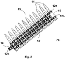
- the figure 2 shows a known example of flexible band 13 of ammunition 11.
- the ammunition 11 is constituted by balls secured by links 12, in this case a link of type M13.
- links 12 in this case a link of type M13.
- Each link has two lateral portions 12a and 12b intended to be clipped on a first bale and a third central portion adapted to be clipped onto the next bale, these two bales being then secured by the link.
- the succession of balls and links form an articulated band 13 having a certain flexibility in the plane of the band and in a plane perpendicular to the plane of the band.
- the band is terminated, at one of its transverse ends 14 by a central portion 12c of a link in which no ball is inserted while on the other side, the central portion 46 of the ball is not enclosed in a central part of a link 12.
- FIGS. 3a to 3e show diagrams of exemplary embodiments of a device according to the invention, hereinafter referred to as a training strip, allowing the introduction of a flexible strip of ammunition inside a conduit from an ammunition box arranged inside a vehicle to the feed opening of a weapon disposed outside the vehicle, this flexible strip comprising munitions connected to each other by links so as to form a strip articulated.
- a device according to the invention comprises a flexible strip 15 1 , 15 2 , 15 3 , 15 4 , 15 5 , in the form of a fishbone or comb and means of attachment 20 one of the transverse ends of this strip at a transverse end of the flexible strip of ammunition.
- Each of the driving belts comprises a longitudinal column 16 arranged along an axis OX and on at least one side of which transverse branches 17, 18, 19, 20, 21 and / or 22 are fixed.
- the attachment means can for example consist of a hook able to cooperate with a free link located at the end of the flexible band of ammunition to allow to secure the ammunition strip to the drive band.
- the Figures 3a, 3b and 3d have a fishbone shaped driving band with a longitudinal column 16 and transverse branches 17, 18, 19, 21 arranged in the same plane P.
- the column 16 constitutes an axis of symmetry of the respective transverse branches 17 and 21, the branches 17 being disposed perpendicularly to said column 16 while the branches 21 form an angle less than 45 degrees with this column.
- the branches 18 disposed on one side of the column 16 are shorter than those 19 disposed on the opposite side of the column 16.
- the Figures 3c and 3e have a comb-shaped drive belt with a lateral longitudinal column 16 and respective transverse branches 20 and 22 arranged in the same plane P and only one side of said column 16, the branches 22 making an angle less than 45 degrees with the column 16 and the branches 20 being perpendicular to said column.
- the transverse branches each comprise an end fixed to said column and arranged successively along the column at an angle ⁇ not zero with said column, namely 90 degrees for the Figures 3a to 3c and about 60 degrees for figures 3d and 3d .
- the figure 4 shows a diagram of an alternative embodiment of a training band 30 according to the invention
- This band 30 comprises a longitudinal column 31 on a first lateral side 32 of which are fixed, with a fixed pitch p, first successive transverse branches 33, and on a second lateral side 34, opposite the first lateral side 32, second branches transverse 35 with the same fixed pitch p but shorter than said first branches, and this, in order to facilitate the flexion of the side of the short branches but also so that the longitudinal column is found in front of the fastening means of the strip according to l invention to the ammunition band.
- This strip also comprises, a portion 36 before, with a transverse branch 37 thicker and therefore more rigid than the transverse branches 33 and 35 and less than the sum, on the one hand the lengths of the first and second branches and on the other hand, the width of the longitudinal column 31.
- the transverse branches located near the thicker branch 37 are also shorter so as to ensure a gradual increase in the width of the band on the front of the band, thus facilitating the introduction and progression of the band within a guide corridor.
- This band also comprises, a rear portion 38, with a transverse branch 39 thicker and therefore more rigid than the transverse branches 33 and 35 and of the same length as the sum of the lengths of the first and second branches and the width of the longitudinal column 31.
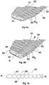
- FIGS. 5a to 5c show the front view, respectively of a first side, the opposite side and longitudinal section along the flexible transverse column axis AA ', of another embodiment of a drive band 50 according to the invention .
- This band 50 has lateral grooves 59 delimiting branches and transverse grooves 49 arranged alternately, the lateral grooves (69) defining transverse branches 53, 55.
- the flexible longitudinal column comprises transverse grooves 49.
- This band 50 comprises a flexible longitudinal column 51 and first transverse branches 53 disposed on a first lateral surface 52 of the column and second transverse branches 55 disposed on a second lateral surface 54 of the column, the first and second surfaces being opposite.
- This band further comprises a transverse branch 57 thicker and therefore more rigid than the transverse branches 53 and 55 and of shorter length than the sum of the lengths of the first and second branches and the width of the longitudinal column 51.
- This figure also shows the regular progression of the width of the band on the front thereof from the thicker transverse branch 57 to the fourth branches 53 4 and 55 4 .
- the branches 53 and 55 have an H-shaped section and the thickness of the second branches 55 is constant along their length while that of the first branches decreases, the latter being equal to that of the column at the level of their joining and decreasing to their end.
- the corridor leads to a window whose dimensions are slightly larger than those of a strip and, in particular, lower on the bullet point side.
- the purpose of decreasing the thickness of the first branches is simply to adapt the thickness of the strip to the section of the window to allow its passage without blocking.
- the H-shape of the branches facilitates their bending along the two axes and their torsion in the thickness.
- the thicker transverse branch 57 has a transverse upper edge 58 chamfered, the chamfer being of variable dimensions because the thickness of this branch 57 is also constant on one side of the axis formed by said column and steadily decreases. other side of this axis, in the same way as the first branches 53.
- the figure 5c shows that the flexible transverse column 51 has transverse grooves 49 on each of its lower 48 and upper 47 faces. These grooves, which in this embodiment are facing, have the function of increasing the flexibility of the band in a perpendicular plane. to that of the transverse branches 53, 55, 57.
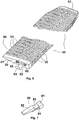
- the figure 6 shows an embodiment of the rear portion 60 of the strip according to the figure 5 .
- This portion 60 has a transverse branch 59 thicker and therefore more rigid than the transverse branches 53 and 55 and of the same length as the sum of the lengths of the first and second branches and the width of the longitudinal column 31.
- the length of the strip 50 is preferably greater than that of the guide channel so that the front end can leave the latter, so a priori sort outside the vehicle and can be recovered by an external operator who can then the shoot and train the ammunition strip.
- the training strip is introduced into the guide lane of the ammunition strips. Its length is such that its front part out of the corridor while its rear part is not yet entered.
- the operator then hooks the free link 73 of a band 70 of ammunition to the hooking means 62, then this operator, or a second fate of the vehicle, pulls on the front part of the drive band 50 to the appearance of the end of the ammunition strip that it introduces into the power supply of the weapon which is then in use.
- Some ammunition bands have links different from those previously presented, for example French links.
- attachment means adapted to this type of means or the attachment of an adapter piece 80 in the end link of the ammunition strip such as for example that presented on the figure 7 , the attachment means 62 of the figure 6 remaining unchanged.
- This adapter piece 80 comprises a first and a second block 81, 82 secured by a central cylindrical portion 83 of diameter equal to that of the inner diameter of the link.
- a rod 84 secured to the first block is disposed parallel to said middle cylindrical portion 83.
- the attachment means can be secured to the drive band at its last branch 59 or
- the first and second branches can be positioned in two different planes, the column being placed at the intersection of the two planes , the cross section at the opposite branches thus forming a circumflex accent.
- branches located on the same side of the column may not all be in the same plane and / or arranged non-regularly or, in other words, with a variable pitch.
- the branches may have a different section of the H, the latter may in particular be square, rectangular, circular, triangular I, U ...
- the attachment means may be independent of a strip according to the invention and have for example a first means, for example a hook, adapted to be hooked to said object, for example at one end of an ammunition strip , and a second means for example another hook, adapted to be attached to a band according to the invention.
- a first means for example a hook
- a second means for example another hook
- all the branches can have the same thickness.
- a roll for example of 50m of tape with a flexible longitudinal column and identical branches evenly distributed along this column. Then simply cut the band to the desired length and possibly chamfering the front of the band and attach a hooking means at the rear of the band.
Landscapes
- Engineering & Computer Science (AREA)
- General Engineering & Computer Science (AREA)
- Operating, Guiding And Securing Of Roll- Type Closing Members (AREA)
- Refuge Islands, Traffic Blockers, Or Guard Fence (AREA)
- Automotive Seat Belt Assembly (AREA)
Claims (11)
- Antriebsgurt (151, 152, 153, 154, 155) zum Einführen eines flexiblen Munitionsgurts (13) mit Verbindungen in eine Zuführung, der eine flexible Längssäule umfasst (31, 51) mit einer Stärke und einer Breite, die mindestens zehnmal geringer ist als ihre Länge und transversal verlaufenden Armen (33, 35, 37, 39, 53, 55, 57) von denen jeder ein Ende aufweist, das an der flexiblen Längssäule (31, 51) befestigt und nacheinander entlang der flexiblen Längssäule (31, 51) in einem Winkel α ungleich Null zur flexiblen Längssäule (31, 51) angeordnet ist, wobei der Gurt (151, 152, 153, 154, 155) dadurch gekennzeichnet ist, dass er an einem seiner transversal verlaufenden Enden, bekannt als hinterer Teil, mit Verhakungsmitteln (20, 41, 62) versehen ist, die, zumindest teilweise, in Längsrichtung aus dem Antriebsgurt herausragen und zum Einhaken des Munitionsgurtes geeignet sind.
- Antriebsgurt (151, 152, 153, 154, 155) nach Anspruch 1, dadurch gekennzeichnet, dass er an einem seiner transversal verlaufenden Enden mit Verhakungsmitteln (20, 41, 62) des transversal verlaufenden Endes zu einer Verbindung eines flexiblen Munitionsgurts (13) versehen ist.
- Antriebsgurt (151, 152, 153, 154, 155) nach einem der vorhergehenden Ansprüche 1 und 2, dadurch gekennzeichnet, dass die Verhakungsmittel (20, 41, 62) mit einem Haken (64) versehen sind, der an einem oder mehreren transversal verlaufenden Armen des Antriebsgurts (151, 152, 153, 154, 155) befestigt ist.
- Antriebsgurt (151, 152, 153, 154, 155) nach Anspruch 3, dadurch gekennzeichnet, dass die Verhakungsmittel (20, 41, 62) mit einem Anschlussteil (80) versehen sind, das im Wesentlichen die Größe einer Munition aufweist und, einerseits, zur Befestigung in einer Endverbindung des flexiblen Munitionsgurts (13), und andererseits, zum Einhaken am Haken geeignet ist.
- Antriebsgurt (151, 152, 153, 154, 155) nach einem der vorhergehenden Ansprüche 1 bis 4, dadurch gekennzeichnet, dass er mit im Wechsel angeordneten lateral verlaufenden Rillen (63) und transversal verlaufenden Rillen (49) versehen ist.
- Antriebsgurt (151, 152, 153, 154, 155) nach einem der vorhergehenden Ansprüche 1 bis 5, dadurch gekennzeichnet, dass mindestens zwei transversal verlaufende Arme (33, 35, 37, 39, 53, 55, 57) mit der flexiblen Längssäule (31, 51) einen Winkel zwischen 30 und 90 Grad oder gleich einem dieser Werte bilden.
- Antriebsgurt (151, 152, 153, 154, 155) nach einem der Ansprüche 1 bis 6, dadurch gekennzeichnet, dass er ein Fischgrätmuster oder eine Kammform aufweist oder dadurch, dass sein Überstand in eine Ebene solch eine Form aufweist.
- Antriebsgurt (151, 152, 153, 154, 155) nach einem der vorhergehenden Ansprüche 1 bis 7, dadurch gekennzeichnet, dass die flexible Längssäule (51) mit transversal verlaufenden Rillen (49) versehen ist.
- Antriebsgurt (151, 152, 153, 154, 155) nach einem der vorhergehenden Ansprüche 1 bis 8, dadurch gekennzeichnet, dass die Arme coplanar oder auf eine Weise angeordnet sind, dass sie einen Accent circonflexe, ein X oder einen Stern bilden.
- Antriebsgurt (151, 152, 153, 154, 155) nach einem der vorhergehenden Ansprüche 1 bis 9, dadurch gekennzeichnet, dass er mit mindestens drei transversal verlaufenden Armen (17, 18, 19, 20, 21, 22, 33, 35, 53, 55) versehen ist, die die gleiche Länge aufweisen und nacheinander in der selben Ebene P angeordnet sind und der Abstand zwischen zwei aufeinanderfolgenden Armen konstant ist.
- Antriebsgurt (151, 152, 153, 154, 155) nach einem der Ansprüche 7 bis 10, dadurch gekennzeichnet, dass er ein Fischgrätmuster oder eine Kammform aufweist und mit einer Längssäule (16, 31, 51) und ersten transversal verlaufenden Armen (18, 33, 53) einer ersten Länge versehen ist, die an einer ersten Seite der Säule (16, 31, 51) befestigt sind und mit zweiten transversal verlaufenden Armen (19, 35, 55) einer zweiten Länge versehen ist, die an einer zweiten Seite der Säule (16, 31, 51) befestigt sind, wobei die erste und die zweite Länge unterschiedlich sind und sich die erste und die zweite Seite gegenüberliegen.
Applications Claiming Priority (2)
| Application Number | Priority Date | Filing Date | Title |
|---|---|---|---|
| FR1200275A FR2986317B1 (fr) | 2012-01-31 | 2012-01-31 | Dispositif d'entrainement permettant l'introduction d'un objet flexible a l'interieur d'un conduit |
| PCT/FR2013/000027 WO2013114010A1 (fr) | 2012-01-31 | 2013-01-29 | Dispositif d'entraînement permettant l'introduction d'un objet flexible à l'intérieur d'un conduit |
Publications (2)
| Publication Number | Publication Date |
|---|---|
| EP2810015A1 EP2810015A1 (de) | 2014-12-10 |
| EP2810015B1 true EP2810015B1 (de) | 2016-12-21 |
Family
ID=47989304
Family Applications (1)
| Application Number | Title | Priority Date | Filing Date |
|---|---|---|---|
| EP13711726.3A Not-in-force EP2810015B1 (de) | 2012-01-31 | 2013-01-29 | Antriebsvorrichtung zum einsetzen eines flexiblen gegenstands in eine leitung |
Country Status (5)
| Country | Link |
|---|---|
| EP (1) | EP2810015B1 (de) |
| CA (1) | CA2862968C (de) |
| ES (1) | ES2616681T3 (de) |
| FR (1) | FR2986317B1 (de) |
| WO (1) | WO2013114010A1 (de) |
Families Citing this family (1)
| Publication number | Priority date | Publication date | Assignee | Title |
|---|---|---|---|---|
| FR2995675B1 (fr) | 2012-09-19 | 2014-09-12 | France Etat | Couloir flexible pour munitions |
Family Cites Families (6)
| Publication number | Priority date | Publication date | Assignee | Title |
|---|---|---|---|---|
| GB574673A (en) * | 1938-10-22 | 1940-04-26 | Boulton Aircraft Ltd | Improved means for feeding ammunition to belt fed machine guns |
| US3435937A (en) * | 1966-12-30 | 1969-04-01 | Gen Electric | Flexible one-piece chute |
| DE2042768C3 (de) * | 1970-08-28 | 1981-01-29 | Hilti Ag, Schaan (Liechtenstein) | Mit Nägeln bestücktes Magazin für ein pulverkraftbetriebenes Setzgerät |
| CH673335A5 (en) * | 1987-07-13 | 1990-02-28 | Oerlikon Buehrle Ag | Ammunition feed system without belt - has conduit of articulated links forming guides for chain and rounds |
| NZ226230A (en) * | 1987-09-18 | 1991-01-29 | Schering Agrochemicals Ltd | Implant gun for use with cartridge of strip form |
| IT1284722B1 (it) | 1996-08-02 | 1998-05-21 | Augusta Spa | Dispositivo di alimentazione di munizioni ad un'arma imbarcata su un aeromobile, ed aeromobile provvisto di tale dispositivo. |
-
2012
- 2012-01-31 FR FR1200275A patent/FR2986317B1/fr not_active Expired - Fee Related
-
2013
- 2013-01-29 EP EP13711726.3A patent/EP2810015B1/de not_active Not-in-force
- 2013-01-29 CA CA2862968A patent/CA2862968C/fr active Active
- 2013-01-29 ES ES13711726.3T patent/ES2616681T3/es active Active
- 2013-01-29 WO PCT/FR2013/000027 patent/WO2013114010A1/fr not_active Ceased
Also Published As
| Publication number | Publication date |
|---|---|
| FR2986317B1 (fr) | 2015-04-03 |
| CA2862968A1 (fr) | 2013-08-08 |
| ES2616681T3 (es) | 2017-06-14 |
| FR2986317A1 (fr) | 2013-08-02 |
| CA2862968C (fr) | 2019-04-09 |
| EP2810015A1 (de) | 2014-12-10 |
| WO2013114010A9 (fr) | 2013-10-17 |
| WO2013114010A1 (fr) | 2013-08-08 |
Similar Documents
| Publication | Publication Date | Title |
|---|---|---|
| CA2614600C (fr) | Eclisse de raccordement de troncons de chemin de cables | |
| FR2701015A1 (fr) | Système de convoyage en translation/rotation d'un élément support. | |
| EP2810015B1 (de) | Antriebsvorrichtung zum einsetzen eines flexiblen gegenstands in eine leitung | |
| FR3035949A1 (fr) | Dispositif pour le demelage et la mise en place de cables | |
| CA2982070C (fr) | Faisceau torsible pour pale, un ensemble de faisceaux torsibles, un rotor et un aeronef | |
| EP2719040B1 (de) | Winkelanschlussteil für einen drahtkabelkanal | |
| BE1023370B1 (fr) | Aile d'aeronef comprenant un volet mobile et un boitier de rangement de tubulure souple | |
| EP3139460A1 (de) | Kabelrinnenabschnitt, kabelrinne und montageverfahren dafür | |
| WO2013007936A2 (fr) | Eclisse pivotante destinée au raccordement de tronçons de chemin de câbles en fils | |
| EP3563067A1 (de) | Bändelungsvorrichtung | |
| CA2884335C (fr) | Couloir flexible notamment pour munitions | |
| FR2928143A1 (fr) | Convoyeur equipe de supports pour le montage d'elements tels qu'un rail de guidage lateral de charges | |
| EP1590273B1 (de) | Palette für eine förderkette | |
| EP3145291A1 (de) | Gekrümmte entastungsklinge, verwendung davon, entsprechender entastungskopf und schneid-kit | |
| EP2605350B1 (de) | Verriegelungssystem von zwei Abschnitten eines Kabelkanals | |
| FR2513449A1 (fr) | Procede et garniture de collier pour le ceinturage d'un faisceau d'elements, notamment de cables | |
| CH684549A5 (fr) | Aile galbée déployable pour engin volant. | |
| FR2581150A1 (fr) | Maille detachable pour raccordement de deux chaines. | |
| FR2968850A1 (fr) | Systeme de verrouillage de deux troncons de chemin de cables | |
| WO2012168644A1 (fr) | Accessoire d'angle pour chemins de cables en fils | |
| EP2456684B1 (de) | Anordnung mit selbstblockierender Schelle | |
| FR2972540A1 (fr) | Dispositif d'extraction d'un element optique dans un cable optique et procede d'extraction associe | |
| WO2024121423A1 (fr) | Bande de convoyeur et procédé de fermeture d'une bande de convoyeur |
Legal Events
| Date | Code | Title | Description |
|---|---|---|---|
| PUAI | Public reference made under article 153(3) epc to a published international application that has entered the european phase |
Free format text: ORIGINAL CODE: 0009012 |
|
| 17P | Request for examination filed |
Effective date: 20140801 |
|
| AK | Designated contracting states |
Kind code of ref document: A1 Designated state(s): AL AT BE BG CH CY CZ DE DK EE ES FI FR GB GR HR HU IE IS IT LI LT LU LV MC MK MT NL NO PL PT RO RS SE SI SK SM TR |
|
| AX | Request for extension of the european patent |
Extension state: BA ME |
|
| DAX | Request for extension of the european patent (deleted) | ||
| GRAP | Despatch of communication of intention to grant a patent |
Free format text: ORIGINAL CODE: EPIDOSNIGR1 |
|
| INTG | Intention to grant announced |
Effective date: 20150723 |
|
| GRAS | Grant fee paid |
Free format text: ORIGINAL CODE: EPIDOSNIGR3 |
|
| INTG | Intention to grant announced |
Effective date: 20160104 |
|
| RAP1 | Party data changed (applicant data changed or rights of an application transferred) |
Owner name: ETAT FRANCAIS REPRESENTE PAR LE DELEGUE GENERAL PO |
|
| GRAA | (expected) grant |
Free format text: ORIGINAL CODE: 0009210 |
|
| AK | Designated contracting states |
Kind code of ref document: B1 Designated state(s): AL AT BE BG CH CY CZ DE DK EE ES FI FR GB GR HR HU IE IS IT LI LT LU LV MC MK MT NL NO PL PT RO RS SE SI SK SM TR |
|
| REG | Reference to a national code |
Ref country code: GB Ref legal event code: FG4D Free format text: NOT ENGLISH |
|
| REG | Reference to a national code |
Ref country code: CH Ref legal event code: EP |
|
| REG | Reference to a national code |
Ref country code: IE Ref legal event code: FG4D Free format text: LANGUAGE OF EP DOCUMENT: FRENCH |
|
| REG | Reference to a national code |
Ref country code: FR Ref legal event code: PLFP Year of fee payment: 5 |
|
| REG | Reference to a national code |
Ref country code: AT Ref legal event code: REF Ref document number: 855860 Country of ref document: AT Kind code of ref document: T Effective date: 20170115 |
|
| REG | Reference to a national code |
Ref country code: DE Ref legal event code: R096 Ref document number: 602013015571 Country of ref document: DE |
|
| PG25 | Lapsed in a contracting state [announced via postgrant information from national office to epo] |
Ref country code: LV Free format text: LAPSE BECAUSE OF FAILURE TO SUBMIT A TRANSLATION OF THE DESCRIPTION OR TO PAY THE FEE WITHIN THE PRESCRIBED TIME-LIMIT Effective date: 20161221 |
|
| REG | Reference to a national code |
Ref country code: SE Ref legal event code: TRGR |
|
| REG | Reference to a national code |
Ref country code: LT Ref legal event code: MG4D |
|
| REG | Reference to a national code |
Ref country code: NL Ref legal event code: MP Effective date: 20161221 |
|
| PG25 | Lapsed in a contracting state [announced via postgrant information from national office to epo] |
Ref country code: GR Free format text: LAPSE BECAUSE OF FAILURE TO SUBMIT A TRANSLATION OF THE DESCRIPTION OR TO PAY THE FEE WITHIN THE PRESCRIBED TIME-LIMIT Effective date: 20170322 Ref country code: LT Free format text: LAPSE BECAUSE OF FAILURE TO SUBMIT A TRANSLATION OF THE DESCRIPTION OR TO PAY THE FEE WITHIN THE PRESCRIBED TIME-LIMIT Effective date: 20161221 |
|
| REG | Reference to a national code |
Ref country code: FR Ref legal event code: PLFP Year of fee payment: 6 |
|
| REG | Reference to a national code |
Ref country code: AT Ref legal event code: MK05 Ref document number: 855860 Country of ref document: AT Kind code of ref document: T Effective date: 20161221 Ref country code: NO Ref legal event code: T2 Effective date: 20161221 |
|
| PG25 | Lapsed in a contracting state [announced via postgrant information from national office to epo] |
Ref country code: RS Free format text: LAPSE BECAUSE OF FAILURE TO SUBMIT A TRANSLATION OF THE DESCRIPTION OR TO PAY THE FEE WITHIN THE PRESCRIBED TIME-LIMIT Effective date: 20161221 Ref country code: FI Free format text: LAPSE BECAUSE OF FAILURE TO SUBMIT A TRANSLATION OF THE DESCRIPTION OR TO PAY THE FEE WITHIN THE PRESCRIBED TIME-LIMIT Effective date: 20161221 Ref country code: HR Free format text: LAPSE BECAUSE OF FAILURE TO SUBMIT A TRANSLATION OF THE DESCRIPTION OR TO PAY THE FEE WITHIN THE PRESCRIBED TIME-LIMIT Effective date: 20161221 |
|
| REG | Reference to a national code |
Ref country code: ES Ref legal event code: FG2A Ref document number: 2616681 Country of ref document: ES Kind code of ref document: T3 Effective date: 20170614 |
|
| PG25 | Lapsed in a contracting state [announced via postgrant information from national office to epo] |
Ref country code: NL Free format text: LAPSE BECAUSE OF FAILURE TO SUBMIT A TRANSLATION OF THE DESCRIPTION OR TO PAY THE FEE WITHIN THE PRESCRIBED TIME-LIMIT Effective date: 20161221 |
|
| PG25 | Lapsed in a contracting state [announced via postgrant information from national office to epo] |
Ref country code: SK Free format text: LAPSE BECAUSE OF FAILURE TO SUBMIT A TRANSLATION OF THE DESCRIPTION OR TO PAY THE FEE WITHIN THE PRESCRIBED TIME-LIMIT Effective date: 20161221 Ref country code: IS Free format text: LAPSE BECAUSE OF FAILURE TO SUBMIT A TRANSLATION OF THE DESCRIPTION OR TO PAY THE FEE WITHIN THE PRESCRIBED TIME-LIMIT Effective date: 20170421 Ref country code: EE Free format text: LAPSE BECAUSE OF FAILURE TO SUBMIT A TRANSLATION OF THE DESCRIPTION OR TO PAY THE FEE WITHIN THE PRESCRIBED TIME-LIMIT Effective date: 20161221 Ref country code: RO Free format text: LAPSE BECAUSE OF FAILURE TO SUBMIT A TRANSLATION OF THE DESCRIPTION OR TO PAY THE FEE WITHIN THE PRESCRIBED TIME-LIMIT Effective date: 20161221 Ref country code: CZ Free format text: LAPSE BECAUSE OF FAILURE TO SUBMIT A TRANSLATION OF THE DESCRIPTION OR TO PAY THE FEE WITHIN THE PRESCRIBED TIME-LIMIT Effective date: 20161221 |
|
| PG25 | Lapsed in a contracting state [announced via postgrant information from national office to epo] |
Ref country code: PL Free format text: LAPSE BECAUSE OF FAILURE TO SUBMIT A TRANSLATION OF THE DESCRIPTION OR TO PAY THE FEE WITHIN THE PRESCRIBED TIME-LIMIT Effective date: 20161221 Ref country code: SM Free format text: LAPSE BECAUSE OF FAILURE TO SUBMIT A TRANSLATION OF THE DESCRIPTION OR TO PAY THE FEE WITHIN THE PRESCRIBED TIME-LIMIT Effective date: 20161221 Ref country code: BG Free format text: LAPSE BECAUSE OF FAILURE TO SUBMIT A TRANSLATION OF THE DESCRIPTION OR TO PAY THE FEE WITHIN THE PRESCRIBED TIME-LIMIT Effective date: 20170321 Ref country code: PT Free format text: LAPSE BECAUSE OF FAILURE TO SUBMIT A TRANSLATION OF THE DESCRIPTION OR TO PAY THE FEE WITHIN THE PRESCRIBED TIME-LIMIT Effective date: 20170421 Ref country code: AT Free format text: LAPSE BECAUSE OF FAILURE TO SUBMIT A TRANSLATION OF THE DESCRIPTION OR TO PAY THE FEE WITHIN THE PRESCRIBED TIME-LIMIT Effective date: 20161221 |
|
| REG | Reference to a national code |
Ref country code: DE Ref legal event code: R097 Ref document number: 602013015571 Country of ref document: DE |
|
| PG25 | Lapsed in a contracting state [announced via postgrant information from national office to epo] |
Ref country code: MC Free format text: LAPSE BECAUSE OF FAILURE TO SUBMIT A TRANSLATION OF THE DESCRIPTION OR TO PAY THE FEE WITHIN THE PRESCRIBED TIME-LIMIT Effective date: 20161221 |
|
| PLBE | No opposition filed within time limit |
Free format text: ORIGINAL CODE: 0009261 |
|
| STAA | Information on the status of an ep patent application or granted ep patent |
Free format text: STATUS: NO OPPOSITION FILED WITHIN TIME LIMIT |
|
| REG | Reference to a national code |
Ref country code: IE Ref legal event code: MM4A |
|
| 26N | No opposition filed |
Effective date: 20170922 |
|
| PG25 | Lapsed in a contracting state [announced via postgrant information from national office to epo] |
Ref country code: DK Free format text: LAPSE BECAUSE OF FAILURE TO SUBMIT A TRANSLATION OF THE DESCRIPTION OR TO PAY THE FEE WITHIN THE PRESCRIBED TIME-LIMIT Effective date: 20161221 Ref country code: LU Free format text: LAPSE BECAUSE OF NON-PAYMENT OF DUE FEES Effective date: 20170129 |
|
| PG25 | Lapsed in a contracting state [announced via postgrant information from national office to epo] |
Ref country code: IE Free format text: LAPSE BECAUSE OF NON-PAYMENT OF DUE FEES Effective date: 20170129 Ref country code: SI Free format text: LAPSE BECAUSE OF FAILURE TO SUBMIT A TRANSLATION OF THE DESCRIPTION OR TO PAY THE FEE WITHIN THE PRESCRIBED TIME-LIMIT Effective date: 20161221 |
|
| REG | Reference to a national code |
Ref country code: FR Ref legal event code: PLFP Year of fee payment: 7 |
|
| PG25 | Lapsed in a contracting state [announced via postgrant information from national office to epo] |
Ref country code: MT Free format text: LAPSE BECAUSE OF FAILURE TO SUBMIT A TRANSLATION OF THE DESCRIPTION OR TO PAY THE FEE WITHIN THE PRESCRIBED TIME-LIMIT Effective date: 20161221 |
|
| PG25 | Lapsed in a contracting state [announced via postgrant information from national office to epo] |
Ref country code: HU Free format text: LAPSE BECAUSE OF FAILURE TO SUBMIT A TRANSLATION OF THE DESCRIPTION OR TO PAY THE FEE WITHIN THE PRESCRIBED TIME-LIMIT; INVALID AB INITIO Effective date: 20130129 |
|
| PG25 | Lapsed in a contracting state [announced via postgrant information from national office to epo] |
Ref country code: CY Free format text: LAPSE BECAUSE OF FAILURE TO SUBMIT A TRANSLATION OF THE DESCRIPTION OR TO PAY THE FEE WITHIN THE PRESCRIBED TIME-LIMIT Effective date: 20161221 |
|
| PG25 | Lapsed in a contracting state [announced via postgrant information from national office to epo] |
Ref country code: MK Free format text: LAPSE BECAUSE OF FAILURE TO SUBMIT A TRANSLATION OF THE DESCRIPTION OR TO PAY THE FEE WITHIN THE PRESCRIBED TIME-LIMIT Effective date: 20161221 |
|
| PG25 | Lapsed in a contracting state [announced via postgrant information from national office to epo] |
Ref country code: TR Free format text: LAPSE BECAUSE OF FAILURE TO SUBMIT A TRANSLATION OF THE DESCRIPTION OR TO PAY THE FEE WITHIN THE PRESCRIBED TIME-LIMIT Effective date: 20161221 |
|
| PG25 | Lapsed in a contracting state [announced via postgrant information from national office to epo] |
Ref country code: AL Free format text: LAPSE BECAUSE OF FAILURE TO SUBMIT A TRANSLATION OF THE DESCRIPTION OR TO PAY THE FEE WITHIN THE PRESCRIBED TIME-LIMIT Effective date: 20161221 |
|
| PGFP | Annual fee paid to national office [announced via postgrant information from national office to epo] |
Ref country code: GB Payment date: 20220121 Year of fee payment: 10 Ref country code: DE Payment date: 20220131 Year of fee payment: 10 Ref country code: CH Payment date: 20220126 Year of fee payment: 10 |
|
| PGFP | Annual fee paid to national office [announced via postgrant information from national office to epo] |
Ref country code: SE Payment date: 20220121 Year of fee payment: 10 Ref country code: NO Payment date: 20220126 Year of fee payment: 10 Ref country code: IT Payment date: 20220125 Year of fee payment: 10 Ref country code: ES Payment date: 20220203 Year of fee payment: 10 Ref country code: BE Payment date: 20220125 Year of fee payment: 10 |
|
| PGFP | Annual fee paid to national office [announced via postgrant information from national office to epo] |
Ref country code: FR Payment date: 20220621 Year of fee payment: 11 |
|
| REG | Reference to a national code |
Ref country code: DE Ref legal event code: R119 Ref document number: 602013015571 Country of ref document: DE |
|
| REG | Reference to a national code |
Ref country code: NO Ref legal event code: MMEP |
|
| REG | Reference to a national code |
Ref country code: SE Ref legal event code: EUG |
|
| REG | Reference to a national code |
Ref country code: CH Ref legal event code: PL |
|
| GBPC | Gb: european patent ceased through non-payment of renewal fee |
Effective date: 20230129 |
|
| REG | Reference to a national code |
Ref country code: BE Ref legal event code: MM Effective date: 20230131 |
|
| PG25 | Lapsed in a contracting state [announced via postgrant information from national office to epo] |
Ref country code: SE Free format text: LAPSE BECAUSE OF NON-PAYMENT OF DUE FEES Effective date: 20230130 Ref country code: NO Free format text: LAPSE BECAUSE OF NON-PAYMENT OF DUE FEES Effective date: 20230131 Ref country code: LI Free format text: LAPSE BECAUSE OF NON-PAYMENT OF DUE FEES Effective date: 20230131 Ref country code: GB Free format text: LAPSE BECAUSE OF NON-PAYMENT OF DUE FEES Effective date: 20230129 Ref country code: DE Free format text: LAPSE BECAUSE OF NON-PAYMENT OF DUE FEES Effective date: 20230801 Ref country code: CH Free format text: LAPSE BECAUSE OF NON-PAYMENT OF DUE FEES Effective date: 20230131 |
|
| PG25 | Lapsed in a contracting state [announced via postgrant information from national office to epo] |
Ref country code: BE Free format text: LAPSE BECAUSE OF NON-PAYMENT OF DUE FEES Effective date: 20230131 |
|
| PG25 | Lapsed in a contracting state [announced via postgrant information from national office to epo] |
Ref country code: IT Free format text: LAPSE BECAUSE OF NON-PAYMENT OF DUE FEES Effective date: 20230129 |
|
| REG | Reference to a national code |
Ref country code: ES Ref legal event code: FD2A Effective date: 20240403 |
|
| PG25 | Lapsed in a contracting state [announced via postgrant information from national office to epo] |
Ref country code: ES Free format text: LAPSE BECAUSE OF NON-PAYMENT OF DUE FEES Effective date: 20230130 |
|
| PG25 | Lapsed in a contracting state [announced via postgrant information from national office to epo] |
Ref country code: ES Free format text: LAPSE BECAUSE OF NON-PAYMENT OF DUE FEES Effective date: 20230130 |
|
| PG25 | Lapsed in a contracting state [announced via postgrant information from national office to epo] |
Ref country code: FR Free format text: LAPSE BECAUSE OF NON-PAYMENT OF DUE FEES Effective date: 20240131 |
|
| PG25 | Lapsed in a contracting state [announced via postgrant information from national office to epo] |
Ref country code: FR Free format text: LAPSE BECAUSE OF NON-PAYMENT OF DUE FEES Effective date: 20240131 |