EP2809537B1 - Gehäuse für ein elektrisches modul eines batteriepacks für ein kraftfahrzeug und zugehöriges batteriepack - Google Patents
Gehäuse für ein elektrisches modul eines batteriepacks für ein kraftfahrzeug und zugehöriges batteriepack Download PDFInfo
- Publication number
- EP2809537B1 EP2809537B1 EP13706614.8A EP13706614A EP2809537B1 EP 2809537 B1 EP2809537 B1 EP 2809537B1 EP 13706614 A EP13706614 A EP 13706614A EP 2809537 B1 EP2809537 B1 EP 2809537B1
- Authority
- EP
- European Patent Office
- Prior art keywords
- wall
- housing
- plate
- relief
- module
- Prior art date
- Legal status (The legal status is an assumption and is not a legal conclusion. Google has not performed a legal analysis and makes no representation as to the accuracy of the status listed.)
- Active
Links
Images


Classifications
-
- B—PERFORMING OPERATIONS; TRANSPORTING
- B60—VEHICLES IN GENERAL
- B60K—ARRANGEMENT OR MOUNTING OF PROPULSION UNITS OR OF TRANSMISSIONS IN VEHICLES; ARRANGEMENT OR MOUNTING OF PLURAL DIVERSE PRIME-MOVERS IN VEHICLES; AUXILIARY DRIVES FOR VEHICLES; INSTRUMENTATION OR DASHBOARDS FOR VEHICLES; ARRANGEMENTS IN CONNECTION WITH COOLING, AIR INTAKE, GAS EXHAUST OR FUEL SUPPLY OF PROPULSION UNITS IN VEHICLES
- B60K1/00—Arrangement or mounting of electrical propulsion units
- B60K1/04—Arrangement or mounting of electrical propulsion units of the electric storage means for propulsion
-
- B—PERFORMING OPERATIONS; TRANSPORTING
- B60—VEHICLES IN GENERAL
- B60L—PROPULSION OF ELECTRICALLY-PROPELLED VEHICLES; SUPPLYING ELECTRIC POWER FOR AUXILIARY EQUIPMENT OF ELECTRICALLY-PROPELLED VEHICLES; ELECTRODYNAMIC BRAKE SYSTEMS FOR VEHICLES IN GENERAL; MAGNETIC SUSPENSION OR LEVITATION FOR VEHICLES; MONITORING OPERATING VARIABLES OF ELECTRICALLY-PROPELLED VEHICLES; ELECTRIC SAFETY DEVICES FOR ELECTRICALLY-PROPELLED VEHICLES
- B60L50/00—Electric propulsion with power supplied within the vehicle
- B60L50/50—Electric propulsion with power supplied within the vehicle using propulsion power supplied by batteries or fuel cells
- B60L50/60—Electric propulsion with power supplied within the vehicle using propulsion power supplied by batteries or fuel cells using power supplied by batteries
- B60L50/64—Constructional details of batteries specially adapted for electric vehicles
-
- F—MECHANICAL ENGINEERING; LIGHTING; HEATING; WEAPONS; BLASTING
- F28—HEAT EXCHANGE IN GENERAL
- F28F—DETAILS OF HEAT-EXCHANGE AND HEAT-TRANSFER APPARATUS, OF GENERAL APPLICATION
- F28F3/00—Plate-like or laminated elements; Assemblies of plate-like or laminated elements
- F28F3/12—Elements constructed in the shape of a hollow panel, e.g. with channels
-
- H—ELECTRICITY
- H01—ELECTRIC ELEMENTS
- H01M—PROCESSES OR MEANS, e.g. BATTERIES, FOR THE DIRECT CONVERSION OF CHEMICAL ENERGY INTO ELECTRICAL ENERGY
- H01M10/00—Secondary cells; Manufacture thereof
- H01M10/60—Heating or cooling; Temperature control
- H01M10/61—Types of temperature control
- H01M10/613—Cooling or keeping cold
-
- H—ELECTRICITY
- H01—ELECTRIC ELEMENTS
- H01M—PROCESSES OR MEANS, e.g. BATTERIES, FOR THE DIRECT CONVERSION OF CHEMICAL ENERGY INTO ELECTRICAL ENERGY
- H01M10/00—Secondary cells; Manufacture thereof
- H01M10/60—Heating or cooling; Temperature control
- H01M10/61—Types of temperature control
- H01M10/617—Types of temperature control for achieving uniformity or desired distribution of temperature
-
- H—ELECTRICITY
- H01—ELECTRIC ELEMENTS
- H01M—PROCESSES OR MEANS, e.g. BATTERIES, FOR THE DIRECT CONVERSION OF CHEMICAL ENERGY INTO ELECTRICAL ENERGY
- H01M10/00—Secondary cells; Manufacture thereof
- H01M10/60—Heating or cooling; Temperature control
- H01M10/62—Heating or cooling; Temperature control specially adapted for specific applications
- H01M10/625—Vehicles
-
- H—ELECTRICITY
- H01—ELECTRIC ELEMENTS
- H01M—PROCESSES OR MEANS, e.g. BATTERIES, FOR THE DIRECT CONVERSION OF CHEMICAL ENERGY INTO ELECTRICAL ENERGY
- H01M10/00—Secondary cells; Manufacture thereof
- H01M10/60—Heating or cooling; Temperature control
- H01M10/64—Heating or cooling; Temperature control characterised by the shape of the cells
- H01M10/647—Prismatic or flat cells, e.g. pouch cells
-
- H—ELECTRICITY
- H01—ELECTRIC ELEMENTS
- H01M—PROCESSES OR MEANS, e.g. BATTERIES, FOR THE DIRECT CONVERSION OF CHEMICAL ENERGY INTO ELECTRICAL ENERGY
- H01M10/00—Secondary cells; Manufacture thereof
- H01M10/60—Heating or cooling; Temperature control
- H01M10/65—Means for temperature control structurally associated with the cells
- H01M10/655—Solid structures for heat exchange or heat conduction
- H01M10/6551—Surfaces specially adapted for heat dissipation or radiation, e.g. fins or coatings
-
- H—ELECTRICITY
- H01—ELECTRIC ELEMENTS
- H01M—PROCESSES OR MEANS, e.g. BATTERIES, FOR THE DIRECT CONVERSION OF CHEMICAL ENERGY INTO ELECTRICAL ENERGY
- H01M10/00—Secondary cells; Manufacture thereof
- H01M10/60—Heating or cooling; Temperature control
- H01M10/65—Means for temperature control structurally associated with the cells
- H01M10/655—Solid structures for heat exchange or heat conduction
- H01M10/6554—Rods or plates
-
- H—ELECTRICITY
- H01—ELECTRIC ELEMENTS
- H01M—PROCESSES OR MEANS, e.g. BATTERIES, FOR THE DIRECT CONVERSION OF CHEMICAL ENERGY INTO ELECTRICAL ENERGY
- H01M10/00—Secondary cells; Manufacture thereof
- H01M10/60—Heating or cooling; Temperature control
- H01M10/65—Means for temperature control structurally associated with the cells
- H01M10/655—Solid structures for heat exchange or heat conduction
- H01M10/6556—Solid parts with flow channel passages or pipes for heat exchange
-
- H—ELECTRICITY
- H01—ELECTRIC ELEMENTS
- H01M—PROCESSES OR MEANS, e.g. BATTERIES, FOR THE DIRECT CONVERSION OF CHEMICAL ENERGY INTO ELECTRICAL ENERGY
- H01M50/00—Constructional details or processes of manufacture of the non-active parts of electrochemical cells other than fuel cells, e.g. hybrid cells
- H01M50/20—Mountings; Secondary casings or frames; Racks, modules or packs; Suspension devices; Shock absorbers; Transport or carrying devices; Holders
- H01M50/204—Racks, modules or packs for multiple batteries or multiple cells
- H01M50/207—Racks, modules or packs for multiple batteries or multiple cells characterised by their shape
- H01M50/209—Racks, modules or packs for multiple batteries or multiple cells characterised by their shape adapted for prismatic or rectangular cells
-
- H—ELECTRICITY
- H01—ELECTRIC ELEMENTS
- H01M—PROCESSES OR MEANS, e.g. BATTERIES, FOR THE DIRECT CONVERSION OF CHEMICAL ENERGY INTO ELECTRICAL ENERGY
- H01M50/00—Constructional details or processes of manufacture of the non-active parts of electrochemical cells other than fuel cells, e.g. hybrid cells
- H01M50/20—Mountings; Secondary casings or frames; Racks, modules or packs; Suspension devices; Shock absorbers; Transport or carrying devices; Holders
- H01M50/218—Mountings; Secondary casings or frames; Racks, modules or packs; Suspension devices; Shock absorbers; Transport or carrying devices; Holders characterised by the material
- H01M50/22—Mountings; Secondary casings or frames; Racks, modules or packs; Suspension devices; Shock absorbers; Transport or carrying devices; Holders characterised by the material of the casings or racks
- H01M50/222—Inorganic material
- H01M50/224—Metals
-
- H—ELECTRICITY
- H01—ELECTRIC ELEMENTS
- H01M—PROCESSES OR MEANS, e.g. BATTERIES, FOR THE DIRECT CONVERSION OF CHEMICAL ENERGY INTO ELECTRICAL ENERGY
- H01M50/00—Constructional details or processes of manufacture of the non-active parts of electrochemical cells other than fuel cells, e.g. hybrid cells
- H01M50/20—Mountings; Secondary casings or frames; Racks, modules or packs; Suspension devices; Shock absorbers; Transport or carrying devices; Holders
- H01M50/218—Mountings; Secondary casings or frames; Racks, modules or packs; Suspension devices; Shock absorbers; Transport or carrying devices; Holders characterised by the material
- H01M50/22—Mountings; Secondary casings or frames; Racks, modules or packs; Suspension devices; Shock absorbers; Transport or carrying devices; Holders characterised by the material of the casings or racks
- H01M50/227—Organic material
-
- H—ELECTRICITY
- H01—ELECTRIC ELEMENTS
- H01M—PROCESSES OR MEANS, e.g. BATTERIES, FOR THE DIRECT CONVERSION OF CHEMICAL ENERGY INTO ELECTRICAL ENERGY
- H01M50/00—Constructional details or processes of manufacture of the non-active parts of electrochemical cells other than fuel cells, e.g. hybrid cells
- H01M50/20—Mountings; Secondary casings or frames; Racks, modules or packs; Suspension devices; Shock absorbers; Transport or carrying devices; Holders
- H01M50/218—Mountings; Secondary casings or frames; Racks, modules or packs; Suspension devices; Shock absorbers; Transport or carrying devices; Holders characterised by the material
- H01M50/22—Mountings; Secondary casings or frames; Racks, modules or packs; Suspension devices; Shock absorbers; Transport or carrying devices; Holders characterised by the material of the casings or racks
- H01M50/229—Composite material consisting of a mixture of organic and inorganic materials
-
- H—ELECTRICITY
- H01—ELECTRIC ELEMENTS
- H01M—PROCESSES OR MEANS, e.g. BATTERIES, FOR THE DIRECT CONVERSION OF CHEMICAL ENERGY INTO ELECTRICAL ENERGY
- H01M50/00—Constructional details or processes of manufacture of the non-active parts of electrochemical cells other than fuel cells, e.g. hybrid cells
- H01M50/20—Mountings; Secondary casings or frames; Racks, modules or packs; Suspension devices; Shock absorbers; Transport or carrying devices; Holders
- H01M50/233—Mountings; Secondary casings or frames; Racks, modules or packs; Suspension devices; Shock absorbers; Transport or carrying devices; Holders characterised by physical properties of casings or racks, e.g. dimensions
- H01M50/24—Mountings; Secondary casings or frames; Racks, modules or packs; Suspension devices; Shock absorbers; Transport or carrying devices; Holders characterised by physical properties of casings or racks, e.g. dimensions adapted for protecting batteries from their environment, e.g. from corrosion
-
- H—ELECTRICITY
- H01—ELECTRIC ELEMENTS
- H01M—PROCESSES OR MEANS, e.g. BATTERIES, FOR THE DIRECT CONVERSION OF CHEMICAL ENERGY INTO ELECTRICAL ENERGY
- H01M50/00—Constructional details or processes of manufacture of the non-active parts of electrochemical cells other than fuel cells, e.g. hybrid cells
- H01M50/20—Mountings; Secondary casings or frames; Racks, modules or packs; Suspension devices; Shock absorbers; Transport or carrying devices; Holders
- H01M50/262—Mountings; Secondary casings or frames; Racks, modules or packs; Suspension devices; Shock absorbers; Transport or carrying devices; Holders with fastening means, e.g. locks
- H01M50/264—Mountings; Secondary casings or frames; Racks, modules or packs; Suspension devices; Shock absorbers; Transport or carrying devices; Holders with fastening means, e.g. locks for cells or batteries, e.g. straps, tie rods or peripheral frames
-
- H—ELECTRICITY
- H01—ELECTRIC ELEMENTS
- H01M—PROCESSES OR MEANS, e.g. BATTERIES, FOR THE DIRECT CONVERSION OF CHEMICAL ENERGY INTO ELECTRICAL ENERGY
- H01M50/00—Constructional details or processes of manufacture of the non-active parts of electrochemical cells other than fuel cells, e.g. hybrid cells
- H01M50/20—Mountings; Secondary casings or frames; Racks, modules or packs; Suspension devices; Shock absorbers; Transport or carrying devices; Holders
- H01M50/271—Lids or covers for the racks or secondary casings
-
- B—PERFORMING OPERATIONS; TRANSPORTING
- B60—VEHICLES IN GENERAL
- B60K—ARRANGEMENT OR MOUNTING OF PROPULSION UNITS OR OF TRANSMISSIONS IN VEHICLES; ARRANGEMENT OR MOUNTING OF PLURAL DIVERSE PRIME-MOVERS IN VEHICLES; AUXILIARY DRIVES FOR VEHICLES; INSTRUMENTATION OR DASHBOARDS FOR VEHICLES; ARRANGEMENTS IN CONNECTION WITH COOLING, AIR INTAKE, GAS EXHAUST OR FUEL SUPPLY OF PROPULSION UNITS IN VEHICLES
- B60K1/00—Arrangement or mounting of electrical propulsion units
- B60K2001/003—Arrangement or mounting of electrical propulsion units with means for cooling the electrical propulsion units
- B60K2001/005—Arrangement or mounting of electrical propulsion units with means for cooling the electrical propulsion units the electric storage means
-
- B—PERFORMING OPERATIONS; TRANSPORTING
- B60—VEHICLES IN GENERAL
- B60K—ARRANGEMENT OR MOUNTING OF PROPULSION UNITS OR OF TRANSMISSIONS IN VEHICLES; ARRANGEMENT OR MOUNTING OF PLURAL DIVERSE PRIME-MOVERS IN VEHICLES; AUXILIARY DRIVES FOR VEHICLES; INSTRUMENTATION OR DASHBOARDS FOR VEHICLES; ARRANGEMENTS IN CONNECTION WITH COOLING, AIR INTAKE, GAS EXHAUST OR FUEL SUPPLY OF PROPULSION UNITS IN VEHICLES
- B60K1/00—Arrangement or mounting of electrical propulsion units
- B60K1/04—Arrangement or mounting of electrical propulsion units of the electric storage means for propulsion
- B60K2001/0405—Arrangement or mounting of electrical propulsion units of the electric storage means for propulsion characterised by their position
- B60K2001/0438—Arrangement under the floor
-
- F—MECHANICAL ENGINEERING; LIGHTING; HEATING; WEAPONS; BLASTING
- F28—HEAT EXCHANGE IN GENERAL
- F28F—DETAILS OF HEAT-EXCHANGE AND HEAT-TRANSFER APPARATUS, OF GENERAL APPLICATION
- F28F13/00—Arrangements for modifying heat-transfer, e.g. increasing, decreasing
- F28F2013/005—Thermal joints
- F28F2013/006—Heat conductive materials
-
- F—MECHANICAL ENGINEERING; LIGHTING; HEATING; WEAPONS; BLASTING
- F28—HEAT EXCHANGE IN GENERAL
- F28F—DETAILS OF HEAT-EXCHANGE AND HEAT-TRANSFER APPARATUS, OF GENERAL APPLICATION
- F28F2275/00—Fastening; Joining
- F28F2275/08—Fastening; Joining by clamping or clipping
-
- H—ELECTRICITY
- H01—ELECTRIC ELEMENTS
- H01M—PROCESSES OR MEANS, e.g. BATTERIES, FOR THE DIRECT CONVERSION OF CHEMICAL ENERGY INTO ELECTRICAL ENERGY
- H01M2220/00—Batteries for particular applications
- H01M2220/20—Batteries in motive systems, e.g. vehicle, ship, plane
-
- Y—GENERAL TAGGING OF NEW TECHNOLOGICAL DEVELOPMENTS; GENERAL TAGGING OF CROSS-SECTIONAL TECHNOLOGIES SPANNING OVER SEVERAL SECTIONS OF THE IPC; TECHNICAL SUBJECTS COVERED BY FORMER USPC CROSS-REFERENCE ART COLLECTIONS [XRACs] AND DIGESTS
- Y02—TECHNOLOGIES OR APPLICATIONS FOR MITIGATION OR ADAPTATION AGAINST CLIMATE CHANGE
- Y02E—REDUCTION OF GREENHOUSE GAS [GHG] EMISSIONS, RELATED TO ENERGY GENERATION, TRANSMISSION OR DISTRIBUTION
- Y02E60/00—Enabling technologies; Technologies with a potential or indirect contribution to GHG emissions mitigation
- Y02E60/10—Energy storage using batteries
-
- Y—GENERAL TAGGING OF NEW TECHNOLOGICAL DEVELOPMENTS; GENERAL TAGGING OF CROSS-SECTIONAL TECHNOLOGIES SPANNING OVER SEVERAL SECTIONS OF THE IPC; TECHNICAL SUBJECTS COVERED BY FORMER USPC CROSS-REFERENCE ART COLLECTIONS [XRACs] AND DIGESTS
- Y02—TECHNOLOGIES OR APPLICATIONS FOR MITIGATION OR ADAPTATION AGAINST CLIMATE CHANGE
- Y02T—CLIMATE CHANGE MITIGATION TECHNOLOGIES RELATED TO TRANSPORTATION
- Y02T10/00—Road transport of goods or passengers
- Y02T10/60—Other road transportation technologies with climate change mitigation effect
- Y02T10/70—Energy storage systems for electromobility, e.g. batteries
Definitions
- the present invention relates to a housing for an electric module of a battery pack for a motor vehicle and such a battery pack.
- the term "cell” means a unitary electrical device capable of producing electric current.
- a cell can produce a voltage current of between 2 and 4 volts, typically 3.7 volts, and is normally intended to be associated with other cells, in a series connection, to provide a higher voltage current. .
- a cell may have a rigid or flexible envelope. In the latter case, we speak of "pouch cell” or “pocket cell”.
- module means a set of several cells having a rigid self-supporting structure, this rigid self-supporting structure being able to be constituted either by a single rigid envelope enclosing several cells with a flexible or rigid envelope, or by the assembly of several cells with rigid envelopes. , juxtaposed next to each other.
- battery pack is understood to mean an electrical assembly containing at least one module and thermal regulation means of this module, in the form of at least one thermoregulatory plate.
- thermoregulatory plate is generally cooled and therefore cooling for the module. However, it is not excluded that it can be used, at least temporarily, to heat a module to bring it to an optimum operating temperature, while the weather conditions are unfavorable.
- the thermoregulatory plate may comprise internal channels for circulating a heat transfer fluid.
- cooling means which may be cooling plates maintained below 43 ° C, heat sinks or cold air circulation systems from the general cooling circuit of the vehicle.
- thermoconductive interface such as a thermally conductive film, sometimes called "thermal pad".
- a thermal pad is a silicon film having a ceramic charge, which improves the thermal conduction between each cell and the cold plate, by compensating for small flatness or alignment defects of the bottom wall of each cell of the cell. module and flatness defects of the cooling plate.
- these compensations are of the order of one tenth of a millimeter, which is not enough to compensate for contact defects in all cell assembly configurations.
- these compensations by a thermally conductive film remain conditioned by a good tightening of the cooling plate against the cells.
- a housing according to the preamble of claim 1 and a battery pack according to the preamble of claim 13 are known from the document EP 2 362 463 A2 .
- the present invention aims to provide a new solution, simple and economical, to ensure thermal contact of excellent quality between a module and a thermoregulatory plate.
- This solution can advantageously be combined with that, already known, of adding a thermally conductive film.
- the present invention relates to a housing of a battery pack for a motor vehicle, comprising an interior space intended to contain at least one module, consisting of a set of several electric cells, associated with a thermoregulatory plate, the housing having at least a wall intended to be against the thermoregulator plate of a module when this module is present in the interior of the housing, this housing being characterized in that it comprises means for clamping a module against said wall and said wall comprises, on its side facing the thermoregulatory plate, a relief element inscribed in a volume having a convexity turned towards the interior space of the housing.
- the wall is understood as the inner face of a partition.
- This partition may be the bottom of the housing, in which case the outer face of the partition is the outer face of the bottom of the housing, or an internal wall of the housing, separating for example two compartments of the latter, in which case the outer face of the partition. is still in the case but not in the interior space containing the module.
- the wall is made of thermoplastic (for example polypropylene) plastic material, thermosetting plastic material (for example polyester), in a mixture of the two previous ones, this material optionally being filled with glass or carbon fibers, polyethylene or any other filler, cast aluminum (eg die cast), cast aluminum.
- thermoplastic for example polypropylene
- thermosetting plastic material for example polyester
- the fact that the relief element is inscribed in a convex volume reflects the fact that it is arranged and sized to transmit to the thermoregulatory plate a clamping pressure exerted by the wall, this clamping pressure being such that the raised element and the wall remain in contact with each other, notwithstanding any possible deformation of the wall caused by the clamping.
- Deformation caused by clamping means any variation in the shape of the wall between the state in which it exerts no pressure on the plate and the state in which it exerts the clamping pressure on the plate. This expression therefore excludes any defects in geometry intrinsic to the wall and obtained independently of the clamping, for example due to a molding defect.
- the deformation considered may be plastic or elastic.
- the convexity of the relief element aims to compensate for the deformations of the wall, generated by the clamping and which are more accentuated at its center than near its edges.
- the person skilled in the art will know, by successive calculations and / or tests, to determine the appropriate height and convexity to compensate exactly for the deformation of the wall, especially in view of the dimensions of the latter, its material, its thickness and the clamping forces.
- the clamping means may consist of closure means of the housing, comprising a bottom and a cover, said bottom or said cover comprising the wall intended to be against the thermoregulatory plate.
- the clamping means may also consist of means for direct attachment of the module to the wall, for example using flanges secured to two opposite side faces of the module, even if the housing is not yet closed. .
- the clamping means define a direction S of clamping, which may be, for example, perpendicular to the wall.
- point a very small surface of the element in relief, comparable to a mathematical point for the purposes of the projection operation, this mathematical point being substantially in the middle of said surface.
- the highest points of the element in relief form a sheet of areas of contact with the thermoregulatory plate which follows a curved shape and ensures effective clamping of said heat-regulating plate, even if the wall deforms during tightening, immediately or with time.
- the contact zones can form a continuous surface or be disjoint, being for example a set of "linear” contact zones (in the sense of reduced to surfaces having a small width and a great length), or even “one-off” (at meaning of reduced to small areas).
- the raised element comprises a solid having a convexity turned towards the inside of the housing.
- the solid comprises a network of ribs projecting from the inner face of the wall and inscribed in a domed envelope towards the inside of the housing, for example in spherical cap, with a vertex substantially in the center of the wall.
- the ribs of the network of ribs are integrally molded with the wall.
- These ribs have a free upper edge opposite their base.
- This free upper edge can follow the convex shape, in which case the contact between each rib and the thermoregulatory plate occurs along the free edge, which defines a linear contact area (in the sense that this narrow and longitudinal area).
- the free upper edge may also be corrugated or crenellated, in which case the contact between each rib and the thermoregulatory plate occurs at the vertices of this free edge, which define point contact zones, formed by said vertices.
- the solid is obtained by giving the wall a convex shape in the direction of the inside of the housing, either because the wall is of relatively constant thickness and concave outside the housing, or because the wall is thickened, for example by being thin near its edges and going thickening towards the center, with its substantially flat outer face. Ribs may be provided on the outer face of the wall, to strengthen it.
- the solid comprises a set of formed pads on the bottom wall and each contact zone is the top of a stud.
- the raised element comprises a block of deformable material having an outer face of convex shape towards the inside of the housing.
- Such a deformable material may be a foam.
- the block of deformable material may have the forms described above, to give contact areas forming a continuous surface or disjoint, being for example a set of linear or point contact areas.
- the wall has a first large dimension L in a first direction, a second large dimension I in a second direction perpendicular to the first.
- the maximum height of the convexity that is, the variation in height between the highest point and the lowest point of the relief element, is preferably less than 2% of one of the two largest dimensions L and I of the wall (that is to say outside its thickness), preferably of the smallest dimension.
- a more preferred range is 0.1% to 2%.
- An even more preferred range is 0.2% to 0.5%.
- the maximum height of the convexity of the raised element may be 2 mm. In absolute values, it will nevertheless be preferable that the maximum height of the convexity does not exceed 5 mm, regardless of the quantities L and I.
- the invention also relates to a battery pack, for a motor vehicle, comprising a housing containing at least one module associated with a thermoregulatory plate, the housing having at least one wall intended to be against the thermoregulator plate of the module, characterized in that this wall comprises, on its inner face facing the thermoregulating plate, a raised element arranged and dimensioned to transmit to the thermoregulatory plate a clamping pressure exerted by the wall, this clamping pressure being such that the element in relief and the thermoregulatory plate remain in contact with each other, notwithstanding any possible deformation of the wall caused by the clamping, this contact occurring at least at points of the element in relief, distributed so that any disk of 20 to 80 mm in diameter, preferably 30 to 60 mm in diameter, drawn by projection on the thermoregulatory plate contain at least two of these points.
- each cell comprises a rigid envelope and the envelopes of the cells of one and the same module are united in a rigid block by being clamped against each other in a transverse direction (with respect to the stacking direction cell - plate - element in relief), with their coplanar bottoms.
- the rigid envelopes of the cells are of prismatic shape, with rectangular bases. Other forms are possible, however.
- each module shares the same temperature-regulating plate.
- each module has its own thermoregulatory plate.
- thermoregulatory plate being immediately present as soon as the clamping of the plate in the housing occurs, and / or in the long term, the conduction between module and thermoregulatory plate is maintained in time to a greater extent than if the thermoregulatory plate had not been tightened in the housing.
- the quality of the contact between the thermoregulatory plate and the module is such that the performance of the thermal exchanges between module and thermoregulatory plate is maintained during the life of the vehicle, without the effects of aging, including variations Temperature, vibrations, creep of materials, are not felt.
- the embossed element according to the invention carries out a sandwiching of the thermoregulatory plate, between this element in relief and the bottom wall of the module (with possibly the interposition of a thermally conductive pad), in a manner distributed over the entire background of the module.
- thermoregulatory plate at the bottom of each of the electric cells constituting the module, but such a measurement would require the presence of means for fixing the plate on the bottom of each cell, and the supply and installation of fasteners on the assembly line of the battery pack, resulting in a significant additional cost of equipment and energy.
- the invention avoids these disadvantages.
- Another advantage resulting from the absence of any need to fix each cell to the plate is that it is thus possible to easily replace a defective module, without having to separate it from the plate, or to purge the coolant circuit flowing through the plate. .
- the raised element comprises a pocket of an incompressible liquid.
- this liquid is a gel.
- the liquid has the advantage of transmitting uniformly and isotropically the pressure that it undergoes and which results from the clamping force of the wall on the plate. It therefore advantageously replaces any other mechanical means aimed at evenly distribute the clamping force of the housing evenly over the thermoregulatory plate.
- liquid or gel may have suitable thermally insulating properties, as well as electrically insulating properties.
- FIG. 1 On the figure 1 , there is shown a battery pack 1, fixed under a floor 3 of a motor vehicle, inside a housing 5 provided for this purpose.
- the floor 3 can be made of polypropylene.
- This arrangement of the battery pack 1 under a floor 3 is only one example which has no limiting character.
- the battery pack 1 better visible on the burst of the figure 2 , comprises a substantially parallelepipedal housing 7 made of mixed material, formed by two halves upper 7a and lower 7b, each of which has a junction flange 8a, 8b.
- the flange 8b of the lower half 7b is provided with a seal 9, shown in the figures 4 and 6 .
- the large lateral faces 11, respectively 13, of the upper half 7a, respectively lower 7b, comprise fixing lugs 15, respectively 17, for fixing the housing 7 to the floor 3.
- the elements present in the housing form two stages E1, E2 of assembled elements, the two stages being substantially identical and each comprising an interior space.
- the invention is not limited to this embodiment and the housing could contain only one floor, or on the contrary more than two floors.
- stage E2 contains the same elements, referenced by the same numbers and the sign '.
- a stage contains here five electrical modules 19-1, 19-2, 19-3, 19-4, 19-5 (generically designated by the reference 19) joined side by side by juxtaposition.
- Each of the modules is itself composed of ten rectangular prismatic cells 21-1-1, 21-1-2, 21-1-3, 21-1-4, 21-1-5, 21-1-6 21-1-7, 21-1-8, 21-1-9, 21-1-10; 21-2-1 to 21-2-10; ...; 21-5-1 to 21-5-10 (generically referred to as 21 below) clamped together by their large side faces and arranged relative to one another so that their bottoms are coplanar and that their small lateral faces are also coplanar, so as to form globally a rectangular parallelepiped.
- Other cell shapes, as well as another configuration of the set of cells forming a module would of course be possible, possibly giving another overall shape to the module, since the bottom of all the cells is plan or substantially plan.
- a module 19-1 (respectively 19-2, 19-3, 19-4, 19-5), the cells are held together by flanks 23-1 (respectively 23-2, 23-3, 23). -4, 23-5, the flanks being designated generically by the reference 23) placed against the two small end faces of the parallelepiped and interconnected by four tie rods 25 (two per large face of the parallelepiped module).
- the five modules are held substantially in the same plane when they are juxtaposed to form a floor of the housing.
- flanks 23 protrude above and below the small end faces of the parallelepiped, leaving, in particular, under the bottoms of the cells 21, a space 31, advantageously of height e between 10 and 20 mm, and more precisely 17 mm in this embodiment.
- the electric modules 19 present the bottoms of their cells 21 substantially in the same lower plane, forming the ceiling of the space 31.
- thermoregulatory plate 33 is placed under all the funds of the cells 21 of the floor. It is here common to the five modules 19. In a variant, each module 19-1 to 19-5 could have its own plate.
- the thermoregulatory plate 33 is sized to fit in the space 31. It is made of aluminum and has, along its long sides, two main channels 35, extended by heat transfer fluid transport tubes 37, each of which opens into a port of the housing 7 visible on the figure 3 . In the stage E2, the tubes 37 'pass through the orifices 39, 41 of the lower half 7b of the housing 7. Each of the main channels 35 communicates with the other through secondary channels (not shown) distributed in the thickness of the plaque.
- Other plate configurations are possible, with, for example, main channels arranged otherwise than along the long sides of the plate.
- the main channels 35 housed in the space 31 with the thermoregulatory plate 33, protrude from this space 31 by a height d .
- thermoregulatory plate 33 On the thermoregulatory plate 33, a thermally conductive film 43 (the film 43 'of the stage E2 is better visible on the figure 6 ), preferably ceramic-filled silicone, is provided to improve the thermal conduction between the modules 19 and the plate 33.
- This film 43 is deformable in a thickness variation, in particular ranging from 0.5 to 1 mm and matches the reliefs due surface imperfections of both the bottoms of the cells 21 and the plate 33, thereby increasing the contact surfaces and, therefore, the heat conduction paths between these two parts.
- the flanks 23 have lower flanges 45, respectively upper 47, which allow their attachment, for example by screws 49, to a partition wall 53 which is, for the upper stage E1, a bottom wall.
- the wall 53 is better visible on the figure 4 .
- the equivalent of the wall 53 is the bottom wall 53 ', which is better seen on the figure 5 .
- the walls 53 and 53 ' are, within the meaning of the invention, walls intended to be against the thermoregulatory plate 33, 33' of a module.
- the housing comprises two interior spaces (not referenced), namely one per floor, each of which is intended to contain a module 19 consisting of a set of several electric cells 21.
- the inner face of a wall 53 or 53 ' designate the face of this wall facing the interior space containing the module 19 interacting with the thermoregulatory plate 33, 33' being in contact with said wall.
- thermoregulatory plate 33 Provided with the film 43
- cells 21 we can see better, in the sectional diagram of the figure 7 , how is the stack of the wall 53, the thermoregulatory plate 33 (provided with the film 43) and the cells 21.
- the wall 53 comprises an array of ribs 55 crossed and perpendicular to its inner face, to the right of the surface of the thermoregulatory plate 33 between its main channels 35.
- the ribs 55 are arranged in a network of crossed ribs inscribed in a domed envelope towards the inside of the housing and constitute, in the sense of the invention, a raised element having a convexity towards the inside of the housing.
- the envelope in which are inscribed the ribs 55 is curved only in a plane normal to the wall and parallel to the direction of its width I.
- the ribs 55 in cross section parallel to the direction of the length L, the ribs 55 have the same height along the entire length L, but this height varies in function of the considered section and is maximum on the central axis of symmetry X of the wall.
- the maximum height of the convexity that is to say the height variation between the lowest point and the highest point of the network of ribs 55 is 1.5 % of the width I (which is the smaller of the two largest dimensions L and I of the wall 53).
- the network of ribs 55 is bordered, on each of its two long longitudinal sides, by a recess 57 of depth d sized to accommodate the main channels 35 of the thermoregulatory plate 33.
- each recess 57 supports 59 parallel to the direction of the width I serve as seats for the lower edges 45 of the flanks 23. Some of these supports 59 incorporate a clamping chimney 60 which is aligned with a hole 44 of the lower flanges. 45 flanks 23.
- Each flange 45 has two orifices 44 and extends over a length corresponding to six supports 59 (numbered in the following first to sixth, in the direction of the length), covering entirely only the second to fifth support 59, while it covers only half of each of the first and sixth supports 59, each of these two supports receiving, on its other half, the adjacent flank of the blank 23 considered.
- the clamping chimneys 60 determine the clamping direction, which is therefore here, as will often be the case, perpendicular to the general plane of the wall 53.
- thermoregulatory plate 33 On the figure 8 the zones of the thermoregulatory plate 33 on which the pressure of the ribs 55 are exerted after tightening are represented.
- zones are referred to as "contact zones”.
- the materialization of the contact zones can be obtained in practice by the deposition of a colored powder on the upper free edges of the ribs 55. During the clamping of the thermoregulatory plate 33 by the bottom wall 53, this powder is transferred to the plate 33 to give the pattern represented in the figure 8 .
- thermoregulator plate 33 there is always at least one contact zone.
- This contact zone corresponds, on the bottom wall 53, to a highest point Hi of the free upper edges of the ribs 55.
- the bottom wall 53 has an uppermost point 81.
- Each of these highest points 63, 67, 71, 75, 79 and 81 is at the top of a rib 55 of the rib network, as shown in section on FIG. figure 9 .
- the vertices of the ribs 55 can be rounded in section, which has the effect of reducing the area of each contact zone.
- the apex of each rib can collapse so that the contact areas are not limited to lines.
- thermoregulatory plate 33 is thus kept in contact with the cells 21 optimally over its entire surface, it being understood that “optimally” means that the contact between these two parts is established at least in certain zones. sufficiently close together so that two neighboring points are not distant more than the distance D, or, in other words, so that any circle of diameter D drawn on the thermoregulatory plate 33 contains at least two of these contact zones, this which reflects a fairly high density and regular points of contact between the plate and the cells.
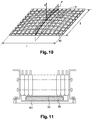
- the wall 53 has two large dimensions L and I. It comprises a raised element consisting of a network of perpendicular crossed ribs 90 with square mesh.
- This network of ribs 90 is convex, in the sense that the vertices of the ribs 90 are inscribed in an upwardly bulging envelope (with respect to the figure).
- the convexity of the envelope is expressed in the two directions of L and I, with a maximum height, that is to say a variation of height between the lowest point and the highest point, advantageously of 2% of I, although, on the schematic representation of the figure 10 the curvature has been accentuated to make clear what this convexity consists of.
- An alternative method consists in finding out if there is a "non-convexity" direction according to which all the points obtained in step 3 present in a plane parallel to this direction have the same height. If this is the case, we execute steps 5 and 6 by choosing a plane P parallel to S and perpendicular to the "non-convexity" direction, by scanning the entire wall at the plane P by translation of pitch D.
- the ribs previously described are replaced by a gel pocket 99.
- the bottom wall 101 of the housing is flat and free of ribs.
- the gel pocket 99 constitutes a raised element of the bottom wall 101, which transmits to the thermoregulatory plate 33, homogeneously at any point on the surface of the latter, the pressure exerted by the bottom wall 101.
- the transmitted pressure is the same at any point of the heat-regulation plate 53, regardless of the deformation experienced by the bottom wall 101 during the tightening of the screws 49 securing the flanks 23 to the bottom wall 101.
Claims (20)
- Gehäuse (7) eines Batteriepacks (1) für Kraftfahrzeug, umfassend einen Innenraum, der dazu bestimmt ist, mindestens ein Modul (19) zu enthalten, das von einer Anordnung aus mehreren elektrischen Zellen (21) gebildet ist, die einer wärmeregulierenden Platte (33) zugeordnet ist, wobei das Gehäuse mindestens eine Wand (53, 53') hat, die dazu bestimmt ist, an der wärmeregulierenden Platte (33) anzuliegen, wenn sich das Modul (19) in dem Gehäuse befindet, wobei dieses Gehäuse dadurch gekennzeichnet ist, dass es Mittel zum Anpressen (23, 49, 60) eines Moduls (19) gegen die Wand (53, 53') aufweist und dass die Wand (53, 53') an ihrer Innenseite, die zu der wärmeregulierenden Platte (33) hin gekehrt ist, ein erhabenes Element (55, 90) aufweist, das sich in ein Volumen einpasst, das eine Konvexität aufweist, die zu dem Innenraum des Gehäuses hin gekehrt ist.
- Gehäuse nach Anspruch 1, dessen Wand (53, 53') aus thermoplastischem Kunststoff oder aus duroplastischem Kunststoff oder aus einem Gemisch der zwei zuvor genannten oder aus geformtem Aluminium oder gegossenem Aluminium ist.
- Gehäuse nach einem der Ansprüche 1 und 2, wobei die Anpressmittel aus Mitteln zum Schließen des Gehäuses bestehen, die einen Boden und einen Deckel umfassen, wobei der Boden oder der Deckel die Wand (53') umfassen, die dazu bestimmt ist, an der wärmeregulierenden Platte (33) anzuliegen.
- Gehäuse nach einem der Ansprüche 1 und 2, wobei die Anpressmittel aus Mitteln zum direkten Befestigen des Moduls (19) an der Wand (53, 53') bestehen, zum Beispiel mit Hilfe von Seitenteilen (23), die an zwei angebrachten Seitenflächen des Moduls (19) befestigt sind.
- Gehäuse nach einem der vorhergehenden Ansprüche, wobei die Anpressmittel eine Anpressrichtung (S) definieren und die Konvexität des erhabenen Elements durch die folgenden Merkmale definiert ist, wobei die Höhen in der Anpressrichtung gemessen sind:- Vorhandensein mindestens eines höchsten Punktes H (81) des erhabenen Elements,- Vorhandensein mindestens einer Projektionsebene P, die durch den höchsten Punktes H (81) verläuft und zu der Anpressrichtung (S) parallel ist, wobei diese Ebene dergestalt ist, dass in der gesamten Zone, die erhalten wird durch Projektion, auf das erhabene Element, einer Scheibe (61, 65, 69, 73, 77) mit einem vorbestimmten Durchmesser, die in einer zweiten Ebene P' liegt, die zu der Anpressrichtung (S) senkrecht ist und durch den höchsten Punktes H (81) des erhabenen Elements verläuft, mindestens ein höchster Punkt Hi (63, 67, 71, 75, 79) vorhanden ist, dessen orthogonale Projektion hi auf die Projektionsebene eine Höhe auf der Projektionsebene hat, die mit dem Abstand zwischen der Projektion und dem höchsten Punkt H (81) zunimmt.
- Gehäuse nach einem der vorhergehenden Ansprüche, wobei das erhabene Element einen Festkörper (55, 90) umfasst, der eine Konvexität aufweist, die zu dem Inneren des Gehäuses hin gekehrt ist.
- Gehäuse nach Anspruch 6, wobei der Festkörper ein Netz aus Rippen (55) umfasst, die von der Innenfläche der Wand vorspringen, und sich in eine Umhüllung einpasst, die zu dem Inneren des Gehäuses hin gewölbt ist.
- Gehäuse nach Anspruch 7, wobei die Rippen (55) des Netzes aus Rippen gemeinsam mit der Wand (53, 53') geformt sind.
- Gehäuse nach Anspruch 6, wobei der Festkörper erhalten wird, in dem der Wand eine Form verliehen wird, die in Richtung des Inneren des Gehäuses konvex ist.
- Gehäuse nach Anspruch 6, wobei der Festkörper eine Anordnung aus Stiften umfasst, die auf der Bodenwand gebildet sind, und jede Kontaktzone die Spitze eines Stiftes ist.
- Gehäuse nach einem der vorhergehenden Ansprüche, wobei das erhabene Element einen verformbaren Materialblock umfasst, der eine Außenfläche hat mit einer Form, die zu dem Inneren des Gehäuses hin konvex ist.
- Gehäuse nach einem der vorhergehenden Ansprüche, wobei die Wand (53, 53') eine erste große Abmessung (L) in einer ersten Richtung aufweist, eine zweite große Abmessung (1) in einer zweiten Richtung, die zu der ersten senkrecht ist, aufweist und wobei die maximale Höhe der Konvexität, das heißt die Abweichung der Höhe zwischen dem höchsten Punkt und dem tiefsten Punkt des erhabenen Elements, zwischen 0,2 % und 0,5 % einer der zwei großen Abmessungen der Wand, vorzugsweise der kleineren Abmessung, und vorzugsweise zwischen 0,1 % und 2 %, und vorzugsweise zwischen 0,2 % und 0,5 % beträgt.
- Batteriepack für Kraftfahrzeug, umfassend ein Gehäuse, das mindestens ein Modul (29) enthält, das von einer Anordnung aus mehreren elektrischen Zellen (21) gebildet ist, die einer wärmeregulierenden Platte (33) zugeordnet ist, wobei das Gehäuse mindestens eine Wand (53, 53') hat, die dazu bestimmt ist, an der wärmeregulierenden Platte (33) des Moduls (29) anzuliegen, dadurch gekennzeichnet, dass diese Wand (53, 53') an ihrer Innenseite, die zu der wärmeregulierenden Platte (33) hin gekehrt ist, ein erhabenes Element (55, 90, 99) aufweist, das dafür eingerichtet und dimensioniert ist, auf die wärmeregulierende Platte (33) einen Anpressdruck zu übertragen, der von der Wand (53, 53') ausgeübt wird, wobei dieser Anpressdruck dergestalt ist, dass das erhabene Element (55, 90, 99) und die wärmeregulierende Platte (33) trotz einer etwaigen Verformung der Wand (53, 53'), die durch das Anpressen bewirkt wird, in Kontakt miteinander bleiben, wobei dieser Kontakt mindestens an Punkten des erhabenen Elements (55, 90, 99) erzeugt wird, die derart verteilt sind, dass jede Scheibe mit einem Durchmesser von 20 bis 80 mm, vorzugsweise mit einem Durchmesser von 30 bis 60 mm, die durch Projektion auf die wärmeregulierende Platte (33) gezeichnet wird, mindestens zwei dieser Punkte enthält.
- Batteriepack nach Anspruch 13, wobei jede Zelle (21) eine starre Umhüllung aufweist und die Umhüllungen der Zellen eines gleichen Moduls (19) in einem starren Block vereint sind, indem sie in einer Querrichtung mit ihren koplanaren Böden gegeneinander gepresst werden.
- Batteriepack nach einem der Ansprüche 13 und 14, wobei die starren Umhüllungen der Zellen (21) eine Prismaform mit rechtwinkligen Basen haben.
- Batteriepack nach einem der Ansprüche 13 bis 15, wobei mehrere Module (19) sich eine gleiche wärmeregulierende Platte (33) teilen.
- Batteriepack nach einem der Ansprüche 13 bis 15, wobei jedes Modul seine eigene wärmeregulierende Platte besitzt.
- Batteriepack nach einem der Ansprüche 13 bis 17, wobei das erhabene Element eine Blase (99) für eine nicht komprimierbare Flüssigkeit oder ein nicht komprimierbares Gel umfasst, die bzw. das in der Lage ist, den Druck, dem sie bzw. es ausgesetzt ist und der aus der Anpresskraft der Wand auf die Platte resultiert, gleichförmig und isotropisch zu übertragen.
- Batteriepack nach Anspruch 18, wobei die Flüssigkeit oder das Gel thermisch isolierende Eigenschaften aufweist.
- Batteriepack nach einem der Ansprüche 18 und 19, wobei die Flüssigkeit oder das Gel elektrisch isolierende Eigenschaften aufweist.
Applications Claiming Priority (2)
| Application Number | Priority Date | Filing Date | Title |
|---|---|---|---|
| FR1250960A FR2986190B1 (fr) | 2012-02-01 | 2012-02-01 | Boitier pour module electrique d'un pack batterie pour vehicule automobile et pack batterie pour vehicule automobile |
| PCT/FR2013/050216 WO2013114054A1 (fr) | 2012-02-01 | 2013-02-01 | Boîtier pour module électrique d'un pack batterie pour véhicule automobile et pack batterie associé |
Publications (2)
| Publication Number | Publication Date |
|---|---|
| EP2809537A1 EP2809537A1 (de) | 2014-12-10 |
| EP2809537B1 true EP2809537B1 (de) | 2016-04-20 |
Family
ID=47754803
Family Applications (1)
| Application Number | Title | Priority Date | Filing Date |
|---|---|---|---|
| EP13706614.8A Active EP2809537B1 (de) | 2012-02-01 | 2013-02-01 | Gehäuse für ein elektrisches modul eines batteriepacks für ein kraftfahrzeug und zugehöriges batteriepack |
Country Status (9)
| Country | Link |
|---|---|
| US (1) | US9818994B2 (de) |
| EP (1) | EP2809537B1 (de) |
| JP (1) | JP6188725B2 (de) |
| KR (1) | KR101986235B1 (de) |
| CN (1) | CN104220286B (de) |
| FR (1) | FR2986190B1 (de) |
| MX (1) | MX2014009376A (de) |
| RU (1) | RU2014135407A (de) |
| WO (1) | WO2013114054A1 (de) |
Families Citing this family (37)
| Publication number | Priority date | Publication date | Assignee | Title |
|---|---|---|---|---|
| JP5811168B2 (ja) * | 2013-12-25 | 2015-11-11 | トヨタ自動車株式会社 | 車両用電池搭載構造 |
| DE102014108160A1 (de) * | 2014-06-11 | 2015-12-17 | Dr. Ing. H.C. F. Porsche Aktiengesellschaft | Unterbodeneinheit für ein Kraftfahrzeug |
| US9825343B2 (en) * | 2014-09-30 | 2017-11-21 | Johnson Controls Technology Company | Battery module passive thermal management features and positioning |
| US9634364B2 (en) * | 2014-10-28 | 2017-04-25 | Ford Global Technologies, Llc | Support structure for traction battery assembly with integrated thermal plate |
| US10347953B2 (en) * | 2014-12-02 | 2019-07-09 | Ford Global Technologies, Llc | Battery module having side compression structure with heat exchanger |
| KR101776853B1 (ko) * | 2015-06-30 | 2017-09-12 | 인지컨트롤스 주식회사 | 배터리 팩 |
| US10497997B2 (en) * | 2016-03-14 | 2019-12-03 | Ford Global Technologies, Llc | Assembly and method to maintain clearance to a thermal fin within a battery assembly |
| US10170810B2 (en) * | 2016-04-18 | 2019-01-01 | Lg Chem, Ltd. | Thermally conductive base member and method of assembling the thermally conductive base member |
| US9979058B2 (en) * | 2016-04-20 | 2018-05-22 | Ford Global Technologies, Llc | Battery thermal energy transfer assembly and method |
| CN109314200B (zh) * | 2016-06-29 | 2022-04-08 | 松下知识产权经营株式会社 | 电池模块 |
| DE102017107203B4 (de) * | 2017-04-04 | 2021-04-22 | Hoppecke Batterien Gmbh & Co. Kg | Traktionsbatterie |
| US10109901B2 (en) * | 2016-07-22 | 2018-10-23 | Ford Global Technologies, Llc | Battery thermal interface material installation assembly and method |
| DE102016009212A1 (de) * | 2016-08-01 | 2018-02-01 | Audi Ag | Batteriemodul und Batterie |
| CN113659260A (zh) * | 2016-11-16 | 2021-11-16 | 奥动新能源汽车科技有限公司 | 一种车载动力电池箱 |
| KR102155330B1 (ko) * | 2016-11-29 | 2020-09-11 | 주식회사 엘지화학 | 공냉식 배터리 모듈 |
| KR102196263B1 (ko) * | 2016-11-30 | 2020-12-29 | 주식회사 엘지화학 | 액상 냉매 사용에 대해 안정성이 향상된 냉각 구조를 가지는 전지팩 |
| JP6813348B2 (ja) * | 2016-12-14 | 2021-01-13 | 株式会社Subaru | 自動車車両 |
| WO2018112619A1 (en) * | 2016-12-19 | 2018-06-28 | Dana Canada Corporation | Battery cooler support architecture |
| EP3582989B1 (de) * | 2017-02-17 | 2022-07-20 | Mubea Carbo Tech GmbH | Batteriestruktur und schutzvorrichtung |
| US10971777B2 (en) * | 2017-04-11 | 2021-04-06 | Ford Global Technologies, Llc | Traction battery support assembly and method |
| EP3529851B1 (de) * | 2017-12-26 | 2021-04-07 | Shin-Etsu Polymer Co., Ltd. | Wärmeableitende struktur und damit ausgestattete batterie |
| KR102526107B1 (ko) | 2018-04-06 | 2023-04-26 | 씨피에스 테크놀로지 홀딩스 엘엘씨 | 배터리 모듈용 열 관리 시스템 |
| DE102018206102A1 (de) * | 2018-04-20 | 2019-10-24 | Thyssenkrupp Ag | Unterfahrschutzanordnung für eine Fahrzeugbatterieanordnung, Fahrzeugbatterieanordnung, Verfahren zur Herstellung einer Unterfahrschutzanordnung, Verfahren zur Herstellung einer Fahrzeugbatterieanordnung |
| DE102018216113A1 (de) * | 2018-09-21 | 2020-03-26 | Audi Ag | Verfahren zum Anordnen zumindest eines Batteriemoduls in zumindest einem Teil eines Batteriegehäuses und Anordnungsvorrichtung |
| KR20200074320A (ko) * | 2018-12-14 | 2020-06-25 | 현대자동차주식회사 | 배터리 팩 |
| DE102019110007B3 (de) | 2019-04-16 | 2020-08-06 | Bayerische Motoren Werke Aktiengesellschaft | Batterieanordnung für ein Fahrzeug umfassend eine Trägervorrichtung mit zwei Aufnahmeräumen sowie Fahrzeug |
| US20220190417A1 (en) * | 2019-04-18 | 2022-06-16 | Cps Technology Holdings Llc | Heat sink fixation through plastic melting |
| KR102053033B1 (ko) | 2019-05-17 | 2019-12-06 | (주)경도시스템 | 배터리팩용 일체형 수납장치 |
| KR20200132628A (ko) | 2019-09-10 | 2020-11-25 | (주)경도시스템 | 배터리팩용 일체형 수납장치 |
| KR20210043990A (ko) * | 2019-10-14 | 2021-04-22 | 주식회사 엘지화학 | 전지팩 및 그 제조 방법 |
| KR102424745B1 (ko) | 2019-12-12 | 2022-07-25 | 한국광기술원 | 배터리 랙 장치 |
| CN111312956B (zh) * | 2020-02-27 | 2022-10-11 | 爱驰汽车有限公司 | 电池包、电池包制造装置以及电池包制造方法 |
| US11588199B2 (en) * | 2020-03-10 | 2023-02-21 | Karma Automotive Llc | Vehicle battery system |
| US11545716B2 (en) * | 2020-10-26 | 2023-01-03 | Ford Global Technologies, Llc | Traction battery upper-tier battery array support assembly and support method |
| JP2022091254A (ja) * | 2020-12-09 | 2022-06-21 | 本田技研工業株式会社 | バッテリケース構造 |
| WO2024054861A1 (en) * | 2022-09-06 | 2024-03-14 | Harbinger Motors Inc. | Battery modules with casted module enclosures and battery packs with safety features |
| DE102022127777A1 (de) | 2022-10-20 | 2024-04-25 | Friedrich Boysen GmbH & Co KG. | Batteriegehäuse |
Family Cites Families (8)
| Publication number | Priority date | Publication date | Assignee | Title |
|---|---|---|---|---|
| JP5098544B2 (ja) * | 2007-09-28 | 2012-12-12 | 三菱自動車工業株式会社 | バッテリユニット |
| CN102105319A (zh) | 2008-06-27 | 2011-06-22 | 普罗特拉公司 | 汽车电池系统和方法 |
| JP2010238554A (ja) | 2009-03-31 | 2010-10-21 | Toyota Motor Corp | 蓄電素子のホルダ |
| DE102009040814A1 (de) * | 2009-09-10 | 2011-03-17 | Behr Gmbh & Co. Kg | Verfahren zur Herstellung eines Energiespeicherhalters für ein Fahrzeug |
| DE102009058070A1 (de) | 2009-12-14 | 2011-06-16 | Behr Gmbh & Co. Kg | Kühlvorrichtung für ein Batteriemodul |
| DE102009058809A1 (de) * | 2009-12-18 | 2011-06-22 | Valeo Klimasysteme GmbH, 96476 | Kühlvorrichtung für eine Fahrzeugantriebsbatterie und Fahrzeugantriebsbatteriebaugruppe mit Kühlvorrichtung |
| JP2011175743A (ja) | 2010-02-23 | 2011-09-08 | Sanyo Electric Co Ltd | 電源装置及びこれを備える車両 |
| WO2012147801A1 (ja) | 2011-04-27 | 2012-11-01 | 三洋電機株式会社 | 電源装置及び電源装置を備える車両 |
-
2012
- 2012-02-01 FR FR1250960A patent/FR2986190B1/fr not_active Expired - Fee Related
-
2013
- 2013-02-01 US US14/375,901 patent/US9818994B2/en active Active
- 2013-02-01 RU RU2014135407A patent/RU2014135407A/ru not_active Application Discontinuation
- 2013-02-01 EP EP13706614.8A patent/EP2809537B1/de active Active
- 2013-02-01 CN CN201380018847.6A patent/CN104220286B/zh active Active
- 2013-02-01 KR KR1020147024474A patent/KR101986235B1/ko active IP Right Grant
- 2013-02-01 WO PCT/FR2013/050216 patent/WO2013114054A1/fr active Application Filing
- 2013-02-01 JP JP2014555290A patent/JP6188725B2/ja not_active Expired - Fee Related
- 2013-02-01 MX MX2014009376A patent/MX2014009376A/es unknown
Also Published As
| Publication number | Publication date |
|---|---|
| RU2014135407A (ru) | 2016-03-27 |
| FR2986190A1 (fr) | 2013-08-02 |
| US20150249238A1 (en) | 2015-09-03 |
| EP2809537A1 (de) | 2014-12-10 |
| FR2986190B1 (fr) | 2015-02-27 |
| KR20140128396A (ko) | 2014-11-05 |
| CN104220286A (zh) | 2014-12-17 |
| JP2015510230A (ja) | 2015-04-02 |
| MX2014009376A (es) | 2015-01-14 |
| US9818994B2 (en) | 2017-11-14 |
| WO2013114054A1 (fr) | 2013-08-08 |
| KR101986235B1 (ko) | 2019-06-07 |
| WO2013114054A9 (fr) | 2014-08-21 |
| CN104220286B (zh) | 2017-03-08 |
| JP6188725B2 (ja) | 2017-08-30 |
Similar Documents
| Publication | Publication Date | Title |
|---|---|---|
| EP2809537B1 (de) | Gehäuse für ein elektrisches modul eines batteriepacks für ein kraftfahrzeug und zugehöriges batteriepack | |
| EP3776686B1 (de) | Batterieeinheit mit integrierten wärmetauschzonen | |
| EP2875547B1 (de) | Batteriemodul mit komprimierten zellen | |
| EP1221728B1 (de) | Wiederverschliessbares Ventil und dieses Ventil enthaltender elektrochemischer Generator | |
| EP2751820B1 (de) | Verbinder zwischen zwei zylindrischen energiespeicherzellen | |
| WO2013113691A1 (fr) | Entretoise de positionnement, module de stockage d'energie l'utilisant et procede d'assemblage du module | |
| FR2988915A3 (fr) | Structure de module de batterie pour cellules li-ion a enveloppe souple et module de batterie correspondant | |
| WO2012168648A1 (fr) | Dispositif de refroidissement de cellules electrochimiques cylindriques | |
| FR2988914A3 (fr) | Structure de module de batterie a assemblage simplifie pour cellules li-ion a enveloppe souple et un module correspondant | |
| EP2751822B1 (de) | Langlebige energiespeichereinrichtung mit einer zwischenverbindung | |
| EP3316350B1 (de) | Elektrisches anschlussstück für akkumulator | |
| EP0522981A1 (de) | Monoblock Akkumulatoren-Batterie | |
| EP4327395A1 (de) | Abgedichtetes gehäuse für elektrische batterie | |
| WO2016156365A1 (fr) | Module de batterie, notamment pour véhicule automobile, et échangeur thermique pour module de batterie correspondant | |
| WO2020201536A1 (fr) | Bloc capacitif comprenant une entretoise | |
| FR3092527A1 (fr) | Boitier pour dispositif de stockage d'énergie électrique pour véhicule automobile | |
| EP3707771B1 (de) | Struktur zur wärmebehandlung einer elektrischen speichervorrichtung für ein kraftfahrzeug | |
| EP4164014A1 (de) | Aufbau eines batteriepacks | |
| FR3081544A1 (fr) | Boite collectrice pour un echangeur de chaleur | |
| WO2018060614A1 (fr) | Element, module et generateur thermoelectriques pour vehicule a moteur thermique et procede de fabrication du module | |
| FR3116655A1 (fr) | Cellule électrochimique de type poche pour un dispositif de stockage d’énergie | |
| WO2018060613A1 (fr) | Module tubulaire unitaire pour vehicule automobile a moteur thermique, et generateur thermoelectrique incorporant plusieurs de ces modules | |
| FR2780814A1 (fr) | Accumulateur couchable a faisceau fixe |
Legal Events
| Date | Code | Title | Description |
|---|---|---|---|
| PUAI | Public reference made under article 153(3) epc to a published international application that has entered the european phase |
Free format text: ORIGINAL CODE: 0009012 |
|
| 17P | Request for examination filed |
Effective date: 20140731 |
|
| AK | Designated contracting states |
Kind code of ref document: A1 Designated state(s): AL AT BE BG CH CY CZ DE DK EE ES FI FR GB GR HR HU IE IS IT LI LT LU LV MC MK MT NL NO PL PT RO RS SE SI SK SM TR |
|
| AX | Request for extension of the european patent |
Extension state: BA ME |
|
| DAX | Request for extension of the european patent (deleted) | ||
| REG | Reference to a national code |
Ref country code: DE Ref legal event code: R079 Ref document number: 602013006720 Country of ref document: DE Free format text: PREVIOUS MAIN CLASS: B60K0001040000 Ipc: B60K0001000000 |
|
| RIC1 | Information provided on ipc code assigned before grant |
Ipc: H01M 10/617 20140101ALI20150901BHEP Ipc: H01M 10/613 20140101ALI20150901BHEP Ipc: H01M 2/10 20060101ALI20150901BHEP Ipc: H01M 10/6554 20140101ALI20150901BHEP Ipc: H01M 10/6551 20140101ALI20150901BHEP Ipc: B60K 1/04 20060101ALI20150901BHEP Ipc: F28F 3/12 20060101ALI20150901BHEP Ipc: B60K 1/00 20060101AFI20150901BHEP Ipc: H01M 10/625 20140101ALI20150901BHEP Ipc: F28F 13/00 20060101ALI20150901BHEP |
|
| GRAP | Despatch of communication of intention to grant a patent |
Free format text: ORIGINAL CODE: EPIDOSNIGR1 |
|
| INTG | Intention to grant announced |
Effective date: 20151009 |
|
| GRAS | Grant fee paid |
Free format text: ORIGINAL CODE: EPIDOSNIGR3 |
|
| GRAA | (expected) grant |
Free format text: ORIGINAL CODE: 0009210 |
|
| AK | Designated contracting states |
Kind code of ref document: B1 Designated state(s): AL AT BE BG CH CY CZ DE DK EE ES FI FR GB GR HR HU IE IS IT LI LT LU LV MC MK MT NL NO PL PT RO RS SE SI SK SM TR |
|
| REG | Reference to a national code |
Ref country code: GB Ref legal event code: FG4D Free format text: NOT ENGLISH |
|
| REG | Reference to a national code |
Ref country code: CH Ref legal event code: EP |
|
| REG | Reference to a national code |
Ref country code: AT Ref legal event code: REF Ref document number: 792008 Country of ref document: AT Kind code of ref document: T Effective date: 20160515 |
|
| REG | Reference to a national code |
Ref country code: IE Ref legal event code: FG4D Free format text: LANGUAGE OF EP DOCUMENT: FRENCH |
|
| REG | Reference to a national code |
Ref country code: DE Ref legal event code: R096 Ref document number: 602013006720 Country of ref document: DE |
|
| REG | Reference to a national code |
Ref country code: DE Ref legal event code: R082 Ref document number: 602013006720 Country of ref document: DE Representative=s name: MAIWALD PATENTANWALTSGESELLSCHAFT MBH, DE Ref country code: DE Ref legal event code: R082 Ref document number: 602013006720 Country of ref document: DE Representative=s name: MAIWALD PATENTANWALTS- UND RECHTSANWALTSGESELL, DE |
|
| REG | Reference to a national code |
Ref country code: LT Ref legal event code: MG4D |
|
| REG | Reference to a national code |
Ref country code: AT Ref legal event code: MK05 Ref document number: 792008 Country of ref document: AT Kind code of ref document: T Effective date: 20160420 |
|
| REG | Reference to a national code |
Ref country code: NL Ref legal event code: MP Effective date: 20160420 |
|
| PG25 | Lapsed in a contracting state [announced via postgrant information from national office to epo] |
Ref country code: LT Free format text: LAPSE BECAUSE OF FAILURE TO SUBMIT A TRANSLATION OF THE DESCRIPTION OR TO PAY THE FEE WITHIN THE PRESCRIBED TIME-LIMIT Effective date: 20160420 Ref country code: PL Free format text: LAPSE BECAUSE OF FAILURE TO SUBMIT A TRANSLATION OF THE DESCRIPTION OR TO PAY THE FEE WITHIN THE PRESCRIBED TIME-LIMIT Effective date: 20160420 Ref country code: FI Free format text: LAPSE BECAUSE OF FAILURE TO SUBMIT A TRANSLATION OF THE DESCRIPTION OR TO PAY THE FEE WITHIN THE PRESCRIBED TIME-LIMIT Effective date: 20160420 Ref country code: NL Free format text: LAPSE BECAUSE OF FAILURE TO SUBMIT A TRANSLATION OF THE DESCRIPTION OR TO PAY THE FEE WITHIN THE PRESCRIBED TIME-LIMIT Effective date: 20160420 Ref country code: NO Free format text: LAPSE BECAUSE OF FAILURE TO SUBMIT A TRANSLATION OF THE DESCRIPTION OR TO PAY THE FEE WITHIN THE PRESCRIBED TIME-LIMIT Effective date: 20160720 |
|
| PG25 | Lapsed in a contracting state [announced via postgrant information from national office to epo] |
Ref country code: PT Free format text: LAPSE BECAUSE OF FAILURE TO SUBMIT A TRANSLATION OF THE DESCRIPTION OR TO PAY THE FEE WITHIN THE PRESCRIBED TIME-LIMIT Effective date: 20160822 Ref country code: ES Free format text: LAPSE BECAUSE OF FAILURE TO SUBMIT A TRANSLATION OF THE DESCRIPTION OR TO PAY THE FEE WITHIN THE PRESCRIBED TIME-LIMIT Effective date: 20160420 Ref country code: GR Free format text: LAPSE BECAUSE OF FAILURE TO SUBMIT A TRANSLATION OF THE DESCRIPTION OR TO PAY THE FEE WITHIN THE PRESCRIBED TIME-LIMIT Effective date: 20160721 Ref country code: SE Free format text: LAPSE BECAUSE OF FAILURE TO SUBMIT A TRANSLATION OF THE DESCRIPTION OR TO PAY THE FEE WITHIN THE PRESCRIBED TIME-LIMIT Effective date: 20160420 Ref country code: RS Free format text: LAPSE BECAUSE OF FAILURE TO SUBMIT A TRANSLATION OF THE DESCRIPTION OR TO PAY THE FEE WITHIN THE PRESCRIBED TIME-LIMIT Effective date: 20160420 Ref country code: LV Free format text: LAPSE BECAUSE OF FAILURE TO SUBMIT A TRANSLATION OF THE DESCRIPTION OR TO PAY THE FEE WITHIN THE PRESCRIBED TIME-LIMIT Effective date: 20160420 Ref country code: AT Free format text: LAPSE BECAUSE OF FAILURE TO SUBMIT A TRANSLATION OF THE DESCRIPTION OR TO PAY THE FEE WITHIN THE PRESCRIBED TIME-LIMIT Effective date: 20160420 Ref country code: HR Free format text: LAPSE BECAUSE OF FAILURE TO SUBMIT A TRANSLATION OF THE DESCRIPTION OR TO PAY THE FEE WITHIN THE PRESCRIBED TIME-LIMIT Effective date: 20160420 |
|
| PG25 | Lapsed in a contracting state [announced via postgrant information from national office to epo] |
Ref country code: IT Free format text: LAPSE BECAUSE OF FAILURE TO SUBMIT A TRANSLATION OF THE DESCRIPTION OR TO PAY THE FEE WITHIN THE PRESCRIBED TIME-LIMIT Effective date: 20160420 |
|
| REG | Reference to a national code |
Ref country code: DE Ref legal event code: R097 Ref document number: 602013006720 Country of ref document: DE |
|
| PG25 | Lapsed in a contracting state [announced via postgrant information from national office to epo] |
Ref country code: CZ Free format text: LAPSE BECAUSE OF FAILURE TO SUBMIT A TRANSLATION OF THE DESCRIPTION OR TO PAY THE FEE WITHIN THE PRESCRIBED TIME-LIMIT Effective date: 20160420 Ref country code: EE Free format text: LAPSE BECAUSE OF FAILURE TO SUBMIT A TRANSLATION OF THE DESCRIPTION OR TO PAY THE FEE WITHIN THE PRESCRIBED TIME-LIMIT Effective date: 20160420 Ref country code: SK Free format text: LAPSE BECAUSE OF FAILURE TO SUBMIT A TRANSLATION OF THE DESCRIPTION OR TO PAY THE FEE WITHIN THE PRESCRIBED TIME-LIMIT Effective date: 20160420 Ref country code: RO Free format text: LAPSE BECAUSE OF FAILURE TO SUBMIT A TRANSLATION OF THE DESCRIPTION OR TO PAY THE FEE WITHIN THE PRESCRIBED TIME-LIMIT Effective date: 20160420 Ref country code: DK Free format text: LAPSE BECAUSE OF FAILURE TO SUBMIT A TRANSLATION OF THE DESCRIPTION OR TO PAY THE FEE WITHIN THE PRESCRIBED TIME-LIMIT Effective date: 20160420 |
|
| REG | Reference to a national code |
Ref country code: FR Ref legal event code: PLFP Year of fee payment: 5 |
|
| PLBE | No opposition filed within time limit |
Free format text: ORIGINAL CODE: 0009261 |
|
| STAA | Information on the status of an ep patent application or granted ep patent |
Free format text: STATUS: NO OPPOSITION FILED WITHIN TIME LIMIT |
|
| PG25 | Lapsed in a contracting state [announced via postgrant information from national office to epo] |
Ref country code: SM Free format text: LAPSE BECAUSE OF FAILURE TO SUBMIT A TRANSLATION OF THE DESCRIPTION OR TO PAY THE FEE WITHIN THE PRESCRIBED TIME-LIMIT Effective date: 20160420 |
|
| 26N | No opposition filed |
Effective date: 20170123 |
|
| PG25 | Lapsed in a contracting state [announced via postgrant information from national office to epo] |
Ref country code: BE Free format text: LAPSE BECAUSE OF NON-PAYMENT OF DUE FEES Effective date: 20170228 Ref country code: SI Free format text: LAPSE BECAUSE OF FAILURE TO SUBMIT A TRANSLATION OF THE DESCRIPTION OR TO PAY THE FEE WITHIN THE PRESCRIBED TIME-LIMIT Effective date: 20160420 |
|
| PG25 | Lapsed in a contracting state [announced via postgrant information from national office to epo] |
Ref country code: MC Free format text: LAPSE BECAUSE OF FAILURE TO SUBMIT A TRANSLATION OF THE DESCRIPTION OR TO PAY THE FEE WITHIN THE PRESCRIBED TIME-LIMIT Effective date: 20160420 |
|
| REG | Reference to a national code |
Ref country code: CH Ref legal event code: PL |
|
| PG25 | Lapsed in a contracting state [announced via postgrant information from national office to epo] |
Ref country code: CH Free format text: LAPSE BECAUSE OF NON-PAYMENT OF DUE FEES Effective date: 20170228 Ref country code: LI Free format text: LAPSE BECAUSE OF NON-PAYMENT OF DUE FEES Effective date: 20170228 |
|
| REG | Reference to a national code |
Ref country code: IE Ref legal event code: MM4A |
|
| PG25 | Lapsed in a contracting state [announced via postgrant information from national office to epo] |
Ref country code: LU Free format text: LAPSE BECAUSE OF NON-PAYMENT OF DUE FEES Effective date: 20170201 |
|
| REG | Reference to a national code |
Ref country code: FR Ref legal event code: PLFP Year of fee payment: 6 |
|
| REG | Reference to a national code |
Ref country code: BE Ref legal event code: MM Effective date: 20170228 |
|
| PG25 | Lapsed in a contracting state [announced via postgrant information from national office to epo] |
Ref country code: IE Free format text: LAPSE BECAUSE OF NON-PAYMENT OF DUE FEES Effective date: 20170201 |
|
| PG25 | Lapsed in a contracting state [announced via postgrant information from national office to epo] |
Ref country code: MT Free format text: LAPSE BECAUSE OF FAILURE TO SUBMIT A TRANSLATION OF THE DESCRIPTION OR TO PAY THE FEE WITHIN THE PRESCRIBED TIME-LIMIT Effective date: 20160420 |
|
| PG25 | Lapsed in a contracting state [announced via postgrant information from national office to epo] |
Ref country code: AL Free format text: LAPSE BECAUSE OF FAILURE TO SUBMIT A TRANSLATION OF THE DESCRIPTION OR TO PAY THE FEE WITHIN THE PRESCRIBED TIME-LIMIT Effective date: 20160420 |
|
| PG25 | Lapsed in a contracting state [announced via postgrant information from national office to epo] |
Ref country code: HU Free format text: LAPSE BECAUSE OF FAILURE TO SUBMIT A TRANSLATION OF THE DESCRIPTION OR TO PAY THE FEE WITHIN THE PRESCRIBED TIME-LIMIT; INVALID AB INITIO Effective date: 20130201 |
|
| PG25 | Lapsed in a contracting state [announced via postgrant information from national office to epo] |
Ref country code: BG Free format text: LAPSE BECAUSE OF FAILURE TO SUBMIT A TRANSLATION OF THE DESCRIPTION OR TO PAY THE FEE WITHIN THE PRESCRIBED TIME-LIMIT Effective date: 20160420 |
|
| PG25 | Lapsed in a contracting state [announced via postgrant information from national office to epo] |
Ref country code: CY Free format text: LAPSE BECAUSE OF FAILURE TO SUBMIT A TRANSLATION OF THE DESCRIPTION OR TO PAY THE FEE WITHIN THE PRESCRIBED TIME-LIMIT Effective date: 20160420 |
|
| PG25 | Lapsed in a contracting state [announced via postgrant information from national office to epo] |
Ref country code: MK Free format text: LAPSE BECAUSE OF FAILURE TO SUBMIT A TRANSLATION OF THE DESCRIPTION OR TO PAY THE FEE WITHIN THE PRESCRIBED TIME-LIMIT Effective date: 20160420 |
|
| PG25 | Lapsed in a contracting state [announced via postgrant information from national office to epo] |
Ref country code: TR Free format text: LAPSE BECAUSE OF FAILURE TO SUBMIT A TRANSLATION OF THE DESCRIPTION OR TO PAY THE FEE WITHIN THE PRESCRIBED TIME-LIMIT Effective date: 20160420 |
|
| PG25 | Lapsed in a contracting state [announced via postgrant information from national office to epo] |
Ref country code: IS Free format text: LAPSE BECAUSE OF FAILURE TO SUBMIT A TRANSLATION OF THE DESCRIPTION OR TO PAY THE FEE WITHIN THE PRESCRIBED TIME-LIMIT Effective date: 20160820 |
|
| PGFP | Annual fee paid to national office [announced via postgrant information from national office to epo] |
Ref country code: FR Payment date: 20230227 Year of fee payment: 11 |
|
| PGFP | Annual fee paid to national office [announced via postgrant information from national office to epo] |
Ref country code: GB Payment date: 20230220 Year of fee payment: 11 Ref country code: DE Payment date: 20230216 Year of fee payment: 11 |