EP2809537B1 - Housing for an electric module of a battery pack for a motor vehicle and corresponding battery pack - Google Patents
Housing for an electric module of a battery pack for a motor vehicle and corresponding battery pack Download PDFInfo
- Publication number
- EP2809537B1 EP2809537B1 EP13706614.8A EP13706614A EP2809537B1 EP 2809537 B1 EP2809537 B1 EP 2809537B1 EP 13706614 A EP13706614 A EP 13706614A EP 2809537 B1 EP2809537 B1 EP 2809537B1
- Authority
- EP
- European Patent Office
- Prior art keywords
- wall
- housing
- plate
- relief
- module
- Prior art date
- Legal status (The legal status is an assumption and is not a legal conclusion. Google has not performed a legal analysis and makes no representation as to the accuracy of the status listed.)
- Active
Links
Images


Classifications
-
- B—PERFORMING OPERATIONS; TRANSPORTING
- B60—VEHICLES IN GENERAL
- B60K—ARRANGEMENT OR MOUNTING OF PROPULSION UNITS OR OF TRANSMISSIONS IN VEHICLES; ARRANGEMENT OR MOUNTING OF PLURAL DIVERSE PRIME-MOVERS IN VEHICLES; AUXILIARY DRIVES FOR VEHICLES; INSTRUMENTATION OR DASHBOARDS FOR VEHICLES; ARRANGEMENTS IN CONNECTION WITH COOLING, AIR INTAKE, GAS EXHAUST OR FUEL SUPPLY OF PROPULSION UNITS IN VEHICLES
- B60K1/00—Arrangement or mounting of electrical propulsion units
- B60K1/04—Arrangement or mounting of electrical propulsion units of the electric storage means for propulsion
-
- B—PERFORMING OPERATIONS; TRANSPORTING
- B60—VEHICLES IN GENERAL
- B60L—PROPULSION OF ELECTRICALLY-PROPELLED VEHICLES; SUPPLYING ELECTRIC POWER FOR AUXILIARY EQUIPMENT OF ELECTRICALLY-PROPELLED VEHICLES; ELECTRODYNAMIC BRAKE SYSTEMS FOR VEHICLES IN GENERAL; MAGNETIC SUSPENSION OR LEVITATION FOR VEHICLES; MONITORING OPERATING VARIABLES OF ELECTRICALLY-PROPELLED VEHICLES; ELECTRIC SAFETY DEVICES FOR ELECTRICALLY-PROPELLED VEHICLES
- B60L50/00—Electric propulsion with power supplied within the vehicle
- B60L50/50—Electric propulsion with power supplied within the vehicle using propulsion power supplied by batteries or fuel cells
- B60L50/60—Electric propulsion with power supplied within the vehicle using propulsion power supplied by batteries or fuel cells using power supplied by batteries
- B60L50/64—Constructional details of batteries specially adapted for electric vehicles
-
- F—MECHANICAL ENGINEERING; LIGHTING; HEATING; WEAPONS; BLASTING
- F28—HEAT EXCHANGE IN GENERAL
- F28F—DETAILS OF HEAT-EXCHANGE AND HEAT-TRANSFER APPARATUS, OF GENERAL APPLICATION
- F28F3/00—Plate-like or laminated elements; Assemblies of plate-like or laminated elements
- F28F3/12—Elements constructed in the shape of a hollow panel, e.g. with channels
-
- H—ELECTRICITY
- H01—ELECTRIC ELEMENTS
- H01M—PROCESSES OR MEANS, e.g. BATTERIES, FOR THE DIRECT CONVERSION OF CHEMICAL ENERGY INTO ELECTRICAL ENERGY
- H01M10/00—Secondary cells; Manufacture thereof
- H01M10/60—Heating or cooling; Temperature control
- H01M10/61—Types of temperature control
- H01M10/613—Cooling or keeping cold
-
- H—ELECTRICITY
- H01—ELECTRIC ELEMENTS
- H01M—PROCESSES OR MEANS, e.g. BATTERIES, FOR THE DIRECT CONVERSION OF CHEMICAL ENERGY INTO ELECTRICAL ENERGY
- H01M10/00—Secondary cells; Manufacture thereof
- H01M10/60—Heating or cooling; Temperature control
- H01M10/61—Types of temperature control
- H01M10/617—Types of temperature control for achieving uniformity or desired distribution of temperature
-
- H—ELECTRICITY
- H01—ELECTRIC ELEMENTS
- H01M—PROCESSES OR MEANS, e.g. BATTERIES, FOR THE DIRECT CONVERSION OF CHEMICAL ENERGY INTO ELECTRICAL ENERGY
- H01M10/00—Secondary cells; Manufacture thereof
- H01M10/60—Heating or cooling; Temperature control
- H01M10/62—Heating or cooling; Temperature control specially adapted for specific applications
- H01M10/625—Vehicles
-
- H—ELECTRICITY
- H01—ELECTRIC ELEMENTS
- H01M—PROCESSES OR MEANS, e.g. BATTERIES, FOR THE DIRECT CONVERSION OF CHEMICAL ENERGY INTO ELECTRICAL ENERGY
- H01M10/00—Secondary cells; Manufacture thereof
- H01M10/60—Heating or cooling; Temperature control
- H01M10/64—Heating or cooling; Temperature control characterised by the shape of the cells
- H01M10/647—Prismatic or flat cells, e.g. pouch cells
-
- H—ELECTRICITY
- H01—ELECTRIC ELEMENTS
- H01M—PROCESSES OR MEANS, e.g. BATTERIES, FOR THE DIRECT CONVERSION OF CHEMICAL ENERGY INTO ELECTRICAL ENERGY
- H01M10/00—Secondary cells; Manufacture thereof
- H01M10/60—Heating or cooling; Temperature control
- H01M10/65—Means for temperature control structurally associated with the cells
- H01M10/655—Solid structures for heat exchange or heat conduction
- H01M10/6551—Surfaces specially adapted for heat dissipation or radiation, e.g. fins or coatings
-
- H—ELECTRICITY
- H01—ELECTRIC ELEMENTS
- H01M—PROCESSES OR MEANS, e.g. BATTERIES, FOR THE DIRECT CONVERSION OF CHEMICAL ENERGY INTO ELECTRICAL ENERGY
- H01M10/00—Secondary cells; Manufacture thereof
- H01M10/60—Heating or cooling; Temperature control
- H01M10/65—Means for temperature control structurally associated with the cells
- H01M10/655—Solid structures for heat exchange or heat conduction
- H01M10/6554—Rods or plates
-
- H—ELECTRICITY
- H01—ELECTRIC ELEMENTS
- H01M—PROCESSES OR MEANS, e.g. BATTERIES, FOR THE DIRECT CONVERSION OF CHEMICAL ENERGY INTO ELECTRICAL ENERGY
- H01M10/00—Secondary cells; Manufacture thereof
- H01M10/60—Heating or cooling; Temperature control
- H01M10/65—Means for temperature control structurally associated with the cells
- H01M10/655—Solid structures for heat exchange or heat conduction
- H01M10/6556—Solid parts with flow channel passages or pipes for heat exchange
-
- H—ELECTRICITY
- H01—ELECTRIC ELEMENTS
- H01M—PROCESSES OR MEANS, e.g. BATTERIES, FOR THE DIRECT CONVERSION OF CHEMICAL ENERGY INTO ELECTRICAL ENERGY
- H01M50/00—Constructional details or processes of manufacture of the non-active parts of electrochemical cells other than fuel cells, e.g. hybrid cells
- H01M50/20—Mountings; Secondary casings or frames; Racks, modules or packs; Suspension devices; Shock absorbers; Transport or carrying devices; Holders
- H01M50/204—Racks, modules or packs for multiple batteries or multiple cells
- H01M50/207—Racks, modules or packs for multiple batteries or multiple cells characterised by their shape
- H01M50/209—Racks, modules or packs for multiple batteries or multiple cells characterised by their shape adapted for prismatic or rectangular cells
-
- H—ELECTRICITY
- H01—ELECTRIC ELEMENTS
- H01M—PROCESSES OR MEANS, e.g. BATTERIES, FOR THE DIRECT CONVERSION OF CHEMICAL ENERGY INTO ELECTRICAL ENERGY
- H01M50/00—Constructional details or processes of manufacture of the non-active parts of electrochemical cells other than fuel cells, e.g. hybrid cells
- H01M50/20—Mountings; Secondary casings or frames; Racks, modules or packs; Suspension devices; Shock absorbers; Transport or carrying devices; Holders
- H01M50/218—Mountings; Secondary casings or frames; Racks, modules or packs; Suspension devices; Shock absorbers; Transport or carrying devices; Holders characterised by the material
- H01M50/22—Mountings; Secondary casings or frames; Racks, modules or packs; Suspension devices; Shock absorbers; Transport or carrying devices; Holders characterised by the material of the casings or racks
- H01M50/222—Inorganic material
- H01M50/224—Metals
-
- H—ELECTRICITY
- H01—ELECTRIC ELEMENTS
- H01M—PROCESSES OR MEANS, e.g. BATTERIES, FOR THE DIRECT CONVERSION OF CHEMICAL ENERGY INTO ELECTRICAL ENERGY
- H01M50/00—Constructional details or processes of manufacture of the non-active parts of electrochemical cells other than fuel cells, e.g. hybrid cells
- H01M50/20—Mountings; Secondary casings or frames; Racks, modules or packs; Suspension devices; Shock absorbers; Transport or carrying devices; Holders
- H01M50/218—Mountings; Secondary casings or frames; Racks, modules or packs; Suspension devices; Shock absorbers; Transport or carrying devices; Holders characterised by the material
- H01M50/22—Mountings; Secondary casings or frames; Racks, modules or packs; Suspension devices; Shock absorbers; Transport or carrying devices; Holders characterised by the material of the casings or racks
- H01M50/227—Organic material
-
- H—ELECTRICITY
- H01—ELECTRIC ELEMENTS
- H01M—PROCESSES OR MEANS, e.g. BATTERIES, FOR THE DIRECT CONVERSION OF CHEMICAL ENERGY INTO ELECTRICAL ENERGY
- H01M50/00—Constructional details or processes of manufacture of the non-active parts of electrochemical cells other than fuel cells, e.g. hybrid cells
- H01M50/20—Mountings; Secondary casings or frames; Racks, modules or packs; Suspension devices; Shock absorbers; Transport or carrying devices; Holders
- H01M50/218—Mountings; Secondary casings or frames; Racks, modules or packs; Suspension devices; Shock absorbers; Transport or carrying devices; Holders characterised by the material
- H01M50/22—Mountings; Secondary casings or frames; Racks, modules or packs; Suspension devices; Shock absorbers; Transport or carrying devices; Holders characterised by the material of the casings or racks
- H01M50/229—Composite material consisting of a mixture of organic and inorganic materials
-
- H—ELECTRICITY
- H01—ELECTRIC ELEMENTS
- H01M—PROCESSES OR MEANS, e.g. BATTERIES, FOR THE DIRECT CONVERSION OF CHEMICAL ENERGY INTO ELECTRICAL ENERGY
- H01M50/00—Constructional details or processes of manufacture of the non-active parts of electrochemical cells other than fuel cells, e.g. hybrid cells
- H01M50/20—Mountings; Secondary casings or frames; Racks, modules or packs; Suspension devices; Shock absorbers; Transport or carrying devices; Holders
- H01M50/233—Mountings; Secondary casings or frames; Racks, modules or packs; Suspension devices; Shock absorbers; Transport or carrying devices; Holders characterised by physical properties of casings or racks, e.g. dimensions
- H01M50/24—Mountings; Secondary casings or frames; Racks, modules or packs; Suspension devices; Shock absorbers; Transport or carrying devices; Holders characterised by physical properties of casings or racks, e.g. dimensions adapted for protecting batteries from their environment, e.g. from corrosion
-
- H—ELECTRICITY
- H01—ELECTRIC ELEMENTS
- H01M—PROCESSES OR MEANS, e.g. BATTERIES, FOR THE DIRECT CONVERSION OF CHEMICAL ENERGY INTO ELECTRICAL ENERGY
- H01M50/00—Constructional details or processes of manufacture of the non-active parts of electrochemical cells other than fuel cells, e.g. hybrid cells
- H01M50/20—Mountings; Secondary casings or frames; Racks, modules or packs; Suspension devices; Shock absorbers; Transport or carrying devices; Holders
- H01M50/262—Mountings; Secondary casings or frames; Racks, modules or packs; Suspension devices; Shock absorbers; Transport or carrying devices; Holders with fastening means, e.g. locks
- H01M50/264—Mountings; Secondary casings or frames; Racks, modules or packs; Suspension devices; Shock absorbers; Transport or carrying devices; Holders with fastening means, e.g. locks for cells or batteries, e.g. straps, tie rods or peripheral frames
-
- H—ELECTRICITY
- H01—ELECTRIC ELEMENTS
- H01M—PROCESSES OR MEANS, e.g. BATTERIES, FOR THE DIRECT CONVERSION OF CHEMICAL ENERGY INTO ELECTRICAL ENERGY
- H01M50/00—Constructional details or processes of manufacture of the non-active parts of electrochemical cells other than fuel cells, e.g. hybrid cells
- H01M50/20—Mountings; Secondary casings or frames; Racks, modules or packs; Suspension devices; Shock absorbers; Transport or carrying devices; Holders
- H01M50/271—Lids or covers for the racks or secondary casings
-
- B—PERFORMING OPERATIONS; TRANSPORTING
- B60—VEHICLES IN GENERAL
- B60K—ARRANGEMENT OR MOUNTING OF PROPULSION UNITS OR OF TRANSMISSIONS IN VEHICLES; ARRANGEMENT OR MOUNTING OF PLURAL DIVERSE PRIME-MOVERS IN VEHICLES; AUXILIARY DRIVES FOR VEHICLES; INSTRUMENTATION OR DASHBOARDS FOR VEHICLES; ARRANGEMENTS IN CONNECTION WITH COOLING, AIR INTAKE, GAS EXHAUST OR FUEL SUPPLY OF PROPULSION UNITS IN VEHICLES
- B60K1/00—Arrangement or mounting of electrical propulsion units
- B60K2001/003—Arrangement or mounting of electrical propulsion units with means for cooling the electrical propulsion units
- B60K2001/005—Arrangement or mounting of electrical propulsion units with means for cooling the electrical propulsion units the electric storage means
-
- B—PERFORMING OPERATIONS; TRANSPORTING
- B60—VEHICLES IN GENERAL
- B60K—ARRANGEMENT OR MOUNTING OF PROPULSION UNITS OR OF TRANSMISSIONS IN VEHICLES; ARRANGEMENT OR MOUNTING OF PLURAL DIVERSE PRIME-MOVERS IN VEHICLES; AUXILIARY DRIVES FOR VEHICLES; INSTRUMENTATION OR DASHBOARDS FOR VEHICLES; ARRANGEMENTS IN CONNECTION WITH COOLING, AIR INTAKE, GAS EXHAUST OR FUEL SUPPLY OF PROPULSION UNITS IN VEHICLES
- B60K1/00—Arrangement or mounting of electrical propulsion units
- B60K1/04—Arrangement or mounting of electrical propulsion units of the electric storage means for propulsion
- B60K2001/0405—Arrangement or mounting of electrical propulsion units of the electric storage means for propulsion characterised by their position
- B60K2001/0438—Arrangement under the floor
-
- F—MECHANICAL ENGINEERING; LIGHTING; HEATING; WEAPONS; BLASTING
- F28—HEAT EXCHANGE IN GENERAL
- F28F—DETAILS OF HEAT-EXCHANGE AND HEAT-TRANSFER APPARATUS, OF GENERAL APPLICATION
- F28F13/00—Arrangements for modifying heat-transfer, e.g. increasing, decreasing
- F28F2013/005—Thermal joints
- F28F2013/006—Heat conductive materials
-
- F—MECHANICAL ENGINEERING; LIGHTING; HEATING; WEAPONS; BLASTING
- F28—HEAT EXCHANGE IN GENERAL
- F28F—DETAILS OF HEAT-EXCHANGE AND HEAT-TRANSFER APPARATUS, OF GENERAL APPLICATION
- F28F2275/00—Fastening; Joining
- F28F2275/08—Fastening; Joining by clamping or clipping
-
- H—ELECTRICITY
- H01—ELECTRIC ELEMENTS
- H01M—PROCESSES OR MEANS, e.g. BATTERIES, FOR THE DIRECT CONVERSION OF CHEMICAL ENERGY INTO ELECTRICAL ENERGY
- H01M2220/00—Batteries for particular applications
- H01M2220/20—Batteries in motive systems, e.g. vehicle, ship, plane
-
- Y—GENERAL TAGGING OF NEW TECHNOLOGICAL DEVELOPMENTS; GENERAL TAGGING OF CROSS-SECTIONAL TECHNOLOGIES SPANNING OVER SEVERAL SECTIONS OF THE IPC; TECHNICAL SUBJECTS COVERED BY FORMER USPC CROSS-REFERENCE ART COLLECTIONS [XRACs] AND DIGESTS
- Y02—TECHNOLOGIES OR APPLICATIONS FOR MITIGATION OR ADAPTATION AGAINST CLIMATE CHANGE
- Y02E—REDUCTION OF GREENHOUSE GAS [GHG] EMISSIONS, RELATED TO ENERGY GENERATION, TRANSMISSION OR DISTRIBUTION
- Y02E60/00—Enabling technologies; Technologies with a potential or indirect contribution to GHG emissions mitigation
- Y02E60/10—Energy storage using batteries
-
- Y—GENERAL TAGGING OF NEW TECHNOLOGICAL DEVELOPMENTS; GENERAL TAGGING OF CROSS-SECTIONAL TECHNOLOGIES SPANNING OVER SEVERAL SECTIONS OF THE IPC; TECHNICAL SUBJECTS COVERED BY FORMER USPC CROSS-REFERENCE ART COLLECTIONS [XRACs] AND DIGESTS
- Y02—TECHNOLOGIES OR APPLICATIONS FOR MITIGATION OR ADAPTATION AGAINST CLIMATE CHANGE
- Y02T—CLIMATE CHANGE MITIGATION TECHNOLOGIES RELATED TO TRANSPORTATION
- Y02T10/00—Road transport of goods or passengers
- Y02T10/60—Other road transportation technologies with climate change mitigation effect
- Y02T10/70—Energy storage systems for electromobility, e.g. batteries
Description
La présente invention concerne un boîtier pour module électrique d'un pack batterie pour véhicule automobile et un tel pack batterie.The present invention relates to a housing for an electric module of a battery pack for a motor vehicle and such a battery pack.
Selon l'invention, on entend par « cellule » un dispositif électrique unitaire capable de produire du courant électrique. Typiquement, une cellule peut produire un courant de tension comprise entre 2 et 4 Volts, en général 3,7 Volts, et est normalement destinée à être associée à d'autres cellules, selon un montage en série, pour fournir un courant de tension supérieure.According to the invention, the term "cell" means a unitary electrical device capable of producing electric current. Typically, a cell can produce a voltage current of between 2 and 4 volts, typically 3.7 volts, and is normally intended to be associated with other cells, in a series connection, to provide a higher voltage current. .
Une cellule peut avoir une enveloppe rigide ou souple. Dans ce dernier cas, on parle de « pouch cell » ou « cellule poche ».A cell may have a rigid or flexible envelope. In the latter case, we speak of "pouch cell" or "pocket cell".
On entend par « module » un ensemble de plusieurs cellules ayant une structure rigide autoporteuse, cette structure rigide autoporteuse pouvant être constituée soit par une enveloppe rigide unique renfermant plusieurs cellules à enveloppe souple ou rigide, soit par l'assemblage de plusieurs cellules à enveloppes rigides, juxtaposées les unes à côté des autres.The term "module" means a set of several cells having a rigid self-supporting structure, this rigid self-supporting structure being able to be constituted either by a single rigid envelope enclosing several cells with a flexible or rigid envelope, or by the assembly of several cells with rigid envelopes. , juxtaposed next to each other.
Enfin, on entend par « pack batterie » un ensemble électrique contenant au moins un module et des moyens de régulation thermique de ce module, sous la forme d'au moins une plaque thermorégulatrice.Finally, "battery pack" is understood to mean an electrical assembly containing at least one module and thermal regulation means of this module, in the form of at least one thermoregulatory plate.
La plaque thermorégulatrice est en général refroidie et, donc, refroidissante pour le module. Toutefois, il n'est pas exclu qu'elle puisse servir, au moins provisoirement, à chauffer un module pour l'amener à une température de fonctionnement optimale, alors que les conditions climatiques sont défavorables. La plaque thermorégulatrice peut comporter des canaux internes de circulation d'un fluide caloporteur.The thermoregulatory plate is generally cooled and therefore cooling for the module. However, it is not excluded that it can be used, at least temporarily, to heat a module to bring it to an optimum operating temperature, while the weather conditions are unfavorable. The thermoregulatory plate may comprise internal channels for circulating a heat transfer fluid.
Dans
Dans un tel ensemble, il est important que les contacts entre les modules et les plaques refroidissantes soient de très bonne qualité. Or, ce résultat n'est pas évident à atteindre car il suppose une très grande précision de dimensionnement, à la fois des cellules et des moyens de refroidissement, ce qui n'est généralement pas le cas. De plus, des variations dimensionnelles de ces constituants peuvent apparaître ou s'accroître au cours de la vie du pack batterie. Un simple empilement, comme proposé dans l'état de la technique, ne fournit donc pas les conditions d'une conduction thermique optimale entre les modules et les moyens de refroidissement.In such an assembly, it is important that the contacts between the modules and the cooling plates are of very good quality. However, this result is not easy to achieve because it assumes a very high design accuracy, both cells and cooling means, which is generally not the case. In addition, dimensional variations of these constituents may appear or increase during the life of the battery pack. A simple stack, as proposed in the state of the art, therefore does not provide the conditions of a optimal thermal conduction between the modules and the cooling means.
Il est par ailleurs connu, face à un problème de conduction thermique entre deux surfaces, d'intercaler entre ces surfaces une interface thermoconductrice, telle qu'un film thermoconducteur, quelquefois appelé « pad thermique ». Un exemple d'un tel pad thermique est un film en silicone ayant une charge céramique, qui améliore la conduction thermique entre chaque cellule et la plaque froide, par compensation des petits défauts de planéité ou d'alignement de la paroi inférieure de chaque cellule du module et des défauts de planéité de la plaque refroidissante. Mais ces compensations sont de l'ordre du dixième de millimètre, ce qui ne suffit pas pour compenser les défauts de contact dans toutes les configurations d'assemblage des cellules. En outre, ces compensations par un film thermoconducteur demeurent conditionnées par un bon serrage de la plaque refroidissante contre les cellules.It is also known, faced with a problem of thermal conduction between two surfaces, to interpose between these surfaces a thermoconductive interface, such as a thermally conductive film, sometimes called "thermal pad". An example of such a thermal pad is a silicon film having a ceramic charge, which improves the thermal conduction between each cell and the cold plate, by compensating for small flatness or alignment defects of the bottom wall of each cell of the cell. module and flatness defects of the cooling plate. But these compensations are of the order of one tenth of a millimeter, which is not enough to compensate for contact defects in all cell assembly configurations. In addition, these compensations by a thermally conductive film remain conditioned by a good tightening of the cooling plate against the cells.
Un boîtier selon le préambule de la revendication 1 et un pack batterie selon le préambule de la revendication 13 sont connus du document
Il existe donc un besoin pour une solution de serrage efficace d'une plaque refroidissante contre le module qu'elle est censée réguler thermiquement.There is therefore a need for an effective clamping solution of a cooling plate against the module it is supposed to thermally regulate.
La présente invention vise à proposer une solution nouvelle, simple et économique, pour garantir un contact thermique d'excellente qualité entre un module et une plaque thermorégulatrice. Cette solution peut avantageusement se cumuler avec celle, déjà connue, d'ajout d'un film thermoconducteur.The present invention aims to provide a new solution, simple and economical, to ensure thermal contact of excellent quality between a module and a thermoregulatory plate. This solution can advantageously be combined with that, already known, of adding a thermally conductive film.
La présente invention a pour objet un boîtier d'un pack batterie pour véhicule automobile, comprenant un espace intérieur destiné à contenir au moins un module, constitué d'un ensemble de plusieurs cellules électriques, associé à une plaque thermorégulatrice, le boîtier ayant au moins une paroi destinée à se trouver contre la plaque thermorégulatrice d'un module lorsque ce module est présent dans l'espace intérieur du boîtier, ce boîtier étant caractérisé en ce qu'il comporte des moyens de serrage d'un module contre ladite paroi et en ce que ladite paroi comporte, sur sa face tournée vers la plaque thermorégulatrice, un élément en relief inscrit dans un volume présentant une convexité tournée vers l'espace intérieur du boîtier.The present invention relates to a housing of a battery pack for a motor vehicle, comprising an interior space intended to contain at least one module, consisting of a set of several electric cells, associated with a thermoregulatory plate, the housing having at least a wall intended to be against the thermoregulator plate of a module when this module is present in the interior of the housing, this housing being characterized in that it comprises means for clamping a module against said wall and said wall comprises, on its side facing the thermoregulatory plate, a relief element inscribed in a volume having a convexity turned towards the interior space of the housing.
Selon l'invention, la paroi s'entend comme la face intérieure d'une cloison. Cette cloison peut être le fond du boîtier, auquel cas la face extérieure de la cloison est la face externe du dessous du boîtier, ou une cloison interne du boîtier, séparant par exemple deux compartiments de ce dernier, auquel cas la face extérieure de la cloison se trouve encore dans le boîtier mais pas dans l'espace intérieur contenant le module.According to the invention, the wall is understood as the inner face of a partition. This partition may be the bottom of the housing, in which case the outer face of the partition is the outer face of the bottom of the housing, or an internal wall of the housing, separating for example two compartments of the latter, in which case the outer face of the partition. is still in the case but not in the interior space containing the module.
Avantageusement, la paroi est en matière plastique thermoplastique (par exemple en polypropylène), en matière plastique thermodurcissable (par exemple en polyester), en un mélange des deux précédents, cette matière étant éventuellement chargée de fibres de verre ou de carbone, de polyéthylène ou de toute autre charge, en aluminium moulé (par exemple moulé sous pression), en aluminium coulé.Advantageously, the wall is made of thermoplastic (for example polypropylene) plastic material, thermosetting plastic material (for example polyester), in a mixture of the two previous ones, this material optionally being filled with glass or carbon fibers, polyethylene or any other filler, cast aluminum (eg die cast), cast aluminum.
Selon l'invention, le fait que l'élément en relief soit inscrit dans un volume convexe traduit le fait qu'il est agencé et dimensionné pour transmettre à la plaque thermorégulatrice une pression de serrage exercée par la paroi, cette pression de serrage étant telle que l'élément en relief et la paroi demeurent en contact l'un avec l'autre, nonobstant une éventuelle déformation de la paroi provoquée par le serrage.According to the invention, the fact that the relief element is inscribed in a convex volume reflects the fact that it is arranged and sized to transmit to the thermoregulatory plate a clamping pressure exerted by the wall, this clamping pressure being such that the raised element and the wall remain in contact with each other, notwithstanding any possible deformation of the wall caused by the clamping.
On entend par "déformation provoquée par le serrage", toute variation de forme de la paroi entre l'état dans lequel elle n'exerce aucune pression sur la plaque et l'état dans lequel elle exerce la pression de serrage sur la plaque. Cette expression exclut donc d'éventuels défauts de géométrie intrinsèques à la paroi et obtenus indépendamment du serrage, par exemple en raison d'un défaut de moulage. La déformation considérée peut être plastique ou élastique."Deformation caused by clamping" means any variation in the shape of the wall between the state in which it exerts no pressure on the plate and the state in which it exerts the clamping pressure on the plate. This expression therefore excludes any defects in geometry intrinsic to the wall and obtained independently of the clamping, for example due to a molding defect. The deformation considered may be plastic or elastic.
La convexité de l'élément en relief vise à compenser les déformations de la paroi, générées par le serrage et qui sont plus accentuées en son centre qu'à proximité de ses bords. L'homme du métier saura, par calculs et/ou essais successifs, déterminer la hauteur et la convexité appropriées pour compenser exactement la déformation de la paroi, compte tenu notamment des dimensions de celle-ci, de sa matière, de son épaisseur et des efforts de serrage.The convexity of the relief element aims to compensate for the deformations of the wall, generated by the clamping and which are more accentuated at its center than near its edges. The person skilled in the art will know, by successive calculations and / or tests, to determine the appropriate height and convexity to compensate exactly for the deformation of the wall, especially in view of the dimensions of the latter, its material, its thickness and the clamping forces.
Les moyens de serrage peuvent consister en des moyens de fermeture du boîtier, comprenant un fond et un couvercle, ledit fond ou ledit couvercle comprenant la paroi destinée à se trouver contre la plaque thermorégulatrice.The clamping means may consist of closure means of the housing, comprising a bottom and a cover, said bottom or said cover comprising the wall intended to be against the thermoregulatory plate.
Les moyens de serrage peuvent aussi être constitués par des moyens de fixation directe du module sur la paroi, par exemple à l'aide de flasques assujettis à deux faces latérales opposées du module, et ce, même si le boîtier n'est pas encore fermé.The clamping means may also consist of means for direct attachment of the module to the wall, for example using flanges secured to two opposite side faces of the module, even if the housing is not yet closed. .
Dans les deux cas, les moyens de serrage définissent une direction S de serrage, qui peut être, par exemple, perpendiculaire à la paroi.In both cases, the clamping means define a direction S of clamping, which may be, for example, perpendicular to the wall.
Dans un mode de réalisation particulier, les moyens de serrage définissant une direction de serrage, la convexité de l'élément en relief est définie par les caractéristiques suivantes, les hauteurs étant mesurées dans la direction de serrage :
- l'existence d'au moins un point H le plus haut (absolu) de l'élément en relief,
- l'existence d'au moins un plan P de projection passant par le point le plus haut (absolu) et parallèle à la direction S de serrage, ce plan étant tel que dans toute zone (obtenue par projection sur l'élément en relief d'un disque d'un diamètre prédéterminé situé dans un deuxième plan P' perpendiculaire à la direction S de serrage et passant par le point le plus haut) de l'élément en relief, il existe au moins un point Hi le plus haut (relatif) dont la projection orthogonale hi sur le plan de projection a une hauteur sur le plan P de projection qui décroit avec la distance entre ladite projection et le point H le plus haut (absolu).
- the existence of at least one H highest point (absolute) of the relief element,
- the existence of at least one plane P of projection passing through the highest point (absolute) and parallel to the direction S of clamping, this plane being such that in any zone (obtained by projection on the element in relief d a disc of a predetermined diameter situated in a second plane P 'perpendicular to the tightening direction S and passing through the highest point) of the element in relief, there exists at least one highest point H i ( relative) whose orthogonal projection h i on the projection plane has a height on the plane P of projection which decreases with the distance between the said projection and the point H the highest (absolute).
Dans la définition ci-dessus, on entend par « point » une surface très réduite de l'élément en relief, assimilable à un point mathématique pour les besoins de l'opération de projection, ce point mathématique étant sensiblement au milieu de ladite surface.In the definition above, the term "point" a very small surface of the element in relief, comparable to a mathematical point for the purposes of the projection operation, this mathematical point being substantially in the middle of said surface.
Ainsi, les points les plus hauts de l'élément en relief forment une nappe de zones de contact avec la plaque thermorégulatrice qui suit une forme bombée et assure un serrage efficace de ladite plaque thermorégulatrice, même si la paroi se déforme lors du serrage, immédiatement ou avec le temps.Thus, the highest points of the element in relief form a sheet of areas of contact with the thermoregulatory plate which follows a curved shape and ensures effective clamping of said heat-regulating plate, even if the wall deforms during tightening, immediately or with time.
Les zones de contact peuvent former une surface continue ou être disjointes, en étant par exemple un ensemble de zones de contact « linéaires » (au sens de réduites à des surfaces ayant une petite largeur et une grande longueur), voire « ponctuelles » (au sens de réduites à de petites surfaces).The contact zones can form a continuous surface or be disjoint, being for example a set of "linear" contact zones (in the sense of reduced to surfaces having a small width and a great length), or even "one-off" (at meaning of reduced to small areas).
Dans un premier mode de réalisation de l'invention, l'élément en relief comprend un solide présentant une convexité tournée vers l'intérieur du boîtier.In a first embodiment of the invention, the raised element comprises a solid having a convexity turned towards the inside of the housing.
Selon une première variante, le solide comprend un réseau de nervures en saillie de la face intérieure de la paroi et inscrit dans une enveloppe bombée vers l'intérieur du boîtier, par exemple en calotte sphérique, avec un sommet sensiblement au centre de la paroi.According to a first variant, the solid comprises a network of ribs projecting from the inner face of the wall and inscribed in a domed envelope towards the inside of the housing, for example in spherical cap, with a vertex substantially in the center of the wall.
De façon avantageuse, les nervures du réseau de nervures sont issues de moulage avec la paroi.Advantageously, the ribs of the network of ribs are integrally molded with the wall.
Ces nervures comportent un bord supérieur libre à l'opposé de leur base.These ribs have a free upper edge opposite their base.
Ce bord supérieur libre peut suivre la forme convexe, auquel cas le contact entre chaque nervure et la plaque thermorégulatrice se produit le long du bord libre, qui définit une zone de contact linéaire (au sens où cette zone étroite et longitudinale).This free upper edge can follow the convex shape, in which case the contact between each rib and the thermoregulatory plate occurs along the free edge, which defines a linear contact area (in the sense that this narrow and longitudinal area).
Le bord supérieur libre peut aussi être ondulé ou crénelé, auquel cas le contact entre chaque nervure et la plaque thermorégulatrice se produit aux sommets de ce bord libre, qui définissent des zones de contact ponctuelles, formées par lesdits sommets.The free upper edge may also be corrugated or crenellated, in which case the contact between each rib and the thermoregulatory plate occurs at the vertices of this free edge, which define point contact zones, formed by said vertices.
Selon une seconde variante de réalisation, le solide est obtenu en donnant à la paroi une forme convexe en direction de l'intérieur du boîtier, soit du fait que la paroi est d'épaisseur relativement constante et concave à l'extérieur du boîtier, soit du fait que la paroi est épaissie, par exemple en étant fine près de ses bords et en allant s'épaississant vers le centre, avec sa face externe sensiblement plane. Des nervures peuvent être prévues sur la face extérieure de la paroi, pour la renforcer.According to a second variant embodiment, the solid is obtained by giving the wall a convex shape in the direction of the inside of the housing, either because the wall is of relatively constant thickness and concave outside the housing, or because the wall is thickened, for example by being thin near its edges and going thickening towards the center, with its substantially flat outer face. Ribs may be provided on the outer face of the wall, to strengthen it.
Selon une troisième variante, le solide comprend un ensemble de plots formés sur la paroi de fond et chaque zone de contact est le sommet d'un plot.According to a third variant, the solid comprises a set of formed pads on the bottom wall and each contact zone is the top of a stud.
Pour vérifier la convexité de l'élément en relief au sens défini précédemment, à savoir :
- l'existence d'au moins un point le plus haut (absolu),
- l'existence d'au moins un plan de projection passant par le point le plus haut et parallèle à la direction de serrage,
- 1 °) Fixer un diamètre D en fonction des dimensions de la plaque et du module. D sera de 20 à 80 mm, de préférence compris entre 30 et 60 mm.
- 2°) Détecter le point H le plus haut (absolu) de l'élément en relief.
- 3°) Etablir, dans le plan passant par H et perpendiculaire à la direction de serrage S, un quadrillage à maile carrée de côté D/√12 (où √2 est la racine carrée de 2) et y tracer des disques sur la surface convexe du solide.
- 4°) Détecter à l'intérieur de chaque zone projetée (qui est presque un disque, à la convexité de la plaque près) le point Hi le plus haut (relativement à cette zone) de l'élément en relief.
- 5°) Prendre un plan P passant par H et parallèle à la direction de serrage et à une première grande dimension de la paroi.
- 6°) Projeter orthogonalement sur le plan P les points Hi les plus hauts obtenus à l'étape 3 qui sont situés à une distance du plan P inférieure au diamètre D, pour obtenir des points hi.
- 7°) Vérifier que, sur le plan P, la ligne brisée passant par tous les points hi et par le point H est convexe.
- 8°) Faire tourner le plan P autour de la direction de serrage à intervalles angulaires réguliers, jusqu'à avoir balayé toute la surface de la paroi, et répéter les étapes 5 et 6 à chaque intervalle.
- the existence of at least one highest point (absolute),
- the existence of at least one projection plane passing through the highest point and parallel to the clamping direction,
- 1 °) Fix a diameter D according to the dimensions of the plate and the module. D will be from 20 to 80 mm, preferably from 30 to 60 mm.
- 2 °) Detect the highest H point (absolute) of the relief element.
- 3 °) Establish, in the plane passing through H and perpendicular to the direction of tightening S, a grid with square mail of side D / √12 (where √2 is the square root of 2) and there to draw disks on the surface convex of the solid.
- 4 °) Detect within each projected area (which is almost a disk, at the convexity of the plate near) the highest point H i (relative to this area) of the relief element.
- 5 °) Take a plane P passing through H and parallel to the tightening direction and a first large dimension of the wall.
- 6 °) Plan orthogonally on the plane P the highest points H i obtained in
step 3 which are located at a distance from the plane P less than the diameter D, to obtain points h i . - 7 °) Check that, on the plane P, the broken line passing through all the points h i and by the point H is convex.
- 8 °) Rotate the plane P around the tightening direction at regular angular intervals, until you have scanned the entire surface of the wall, and repeat
steps 5 and 6 at each interval.
Dans un deuxième mode de réalisation de l'invention, compatible avec le précédent, l'élément en relief comprend un bloc de matière déformable ayant une face externe de forme convexe vers l'intérieur du boîtier.In a second embodiment of the invention, compatible with the above, the raised element comprises a block of deformable material having an outer face of convex shape towards the inside of the housing.
Une telle matière déformable peut être une mousse.Such a deformable material may be a foam.
Le bloc de matière déformable peut présenter les formes décrites précédemment, pour donner des zones de contact formant une surface continue ou disjointes, en étant par exemple un ensemble de zones de contact linéaires ou ponctuelles.The block of deformable material may have the forms described above, to give contact areas forming a continuous surface or disjoint, being for example a set of linear or point contact areas.
Les modes de réalisation précédents peuvent se combiner. Entre par exemple dans la portée de l'invention un boîtier ayant une paroi de fond épaissie et complétée par un solide présentant une convexité vers l'intérieur du boîtier.The previous embodiments can be combined. For example, within the scope of the invention, there is a housing having a thickened bottom wall and supplemented by a solid having a convexity towards the inside of the housing.
Avantageusement, la paroi possède une première grande dimension L selon une première direction, une deuxième grande dimension I selon une deuxième direction perpendiculaire à la première. Lorsque l'élément en relief présente une convexité tournée vers l'intérieur, comme dans le cas d'un réseau de nervures ou d'une paroi ou d'un bloc de mousse de forme convexe, la hauteur maximale de la convexité, c'est-à-dire la variation de hauteur entre le point le plus haut et le point de plus bas de l'élément en relief, est de préférence inférieure à 2% d'une des deux plus grandes dimensions L et I de la paroi (c'est-à-dire hors son épaisseur), de préférence de la dimension la plus petite. Un intervalle davantage préféré est 0,1% à 2%. Un intervalle encore davantage préféré est 0,2% à 0,5%. Ainsi, pour une paroi carrée de 500 mm de côté, la hauteur maximale de la convexité de l'élément en relief peut être de 2 mm. En valeurs absolues, il sera néanmoins préférable que la hauteur maximale de la convexité ne dépasse pas 5 mm, quelles que soient les grandeurs L et I.Advantageously, the wall has a first large dimension L in a first direction, a second large dimension I in a second direction perpendicular to the first. When the raised element has an inwardly turned convexity, as in the case of a network of ribs or a convex shaped wall or block of foam, the maximum height of the convexity, that is, the variation in height between the highest point and the lowest point of the relief element, is preferably less than 2% of one of the two largest dimensions L and I of the wall ( that is to say outside its thickness), preferably of the smallest dimension. A more preferred range is 0.1% to 2%. An even more preferred range is 0.2% to 0.5%. Thus, for a square wall of 500 mm side, the maximum height of the convexity of the raised element may be 2 mm. In absolute values, it will nevertheless be preferable that the maximum height of the convexity does not exceed 5 mm, regardless of the quantities L and I.
L'invention a également pour objet un pack batterie, pour véhicule automobile, comprenant un boîtier contenant au moins un module associé à une plaque thermorégulatrice, le boîtier ayant au moins une paroi destinée à se trouver contre la plaque thermorégulatrice du module, caractérisé en ce que cette paroi comporte, sur sa face intérieure tournée vers la plaque thermorégulatrice, un élément en relief agencé et dimensionné pour transmettre à la plaque thermorégulatrice une pression de serrage exercée par la paroi, cette pression de serrage étant telle que l'élément en relief et la plaque thermorégulatrice demeurent en contact l'un avec l'autre, nonobstant une éventuelle déformation de la paroi provoquée par le serrage, ce contact se produisant au moins en des points de l'élément en relief, répartis de telle sorte que tout disque de 20 à 80 mm de diamètre, de préférence 30 à 60 mm de diamètre, dessiné par projection sur la plaque thermorégulatrice contienne au moins deux de ces points.The invention also relates to a battery pack, for a motor vehicle, comprising a housing containing at least one module associated with a thermoregulatory plate, the housing having at least one wall intended to be against the thermoregulator plate of the module, characterized in that this wall comprises, on its inner face facing the thermoregulating plate, a raised element arranged and dimensioned to transmit to the thermoregulatory plate a clamping pressure exerted by the wall, this clamping pressure being such that the element in relief and the thermoregulatory plate remain in contact with each other, notwithstanding any possible deformation of the wall caused by the clamping, this contact occurring at least at points of the element in relief, distributed so that any disk of 20 to 80 mm in diameter, preferably 30 to 60 mm in diameter, drawn by projection on the thermoregulatory plate contain at least two of these points.
Dans un mode de réalisation particulier, chaque cellule comporte une enveloppe rigide et les enveloppes des cellules d'un même module sont réunies en un bloc rigide en étant serrées les unes contre les autres selon une direction transversale (par rapport à la direction d'empilement cellule - plaque - élément en relief), avec leurs fonds coplanaires.In a particular embodiment, each cell comprises a rigid envelope and the envelopes of the cells of one and the same module are united in a rigid block by being clamped against each other in a transverse direction (with respect to the stacking direction cell - plate - element in relief), with their coplanar bottoms.
De façon préférée, les enveloppes rigides des cellules sont de forme prismatique, avec des bases rectangulaires. D'autres formes sont cependant possibles.Preferably, the rigid envelopes of the cells are of prismatic shape, with rectangular bases. Other forms are possible, however.
Dans un mode de réalisation particulier, plusieurs modules partagent une même plaque thermorégulatrice. Dans un autre mode de réalisation, chaque module possède sa propre plaque thermorégulatrice.In a particular embodiment, several modules share the same temperature-regulating plate. In another embodiment, each module has its own thermoregulatory plate.
Selon l'invention, l'obtention d'une bonne conduction thermique s'entend à court terme, la conduction entre module et plaque thermorégulatrice étant immédiatement présente dès que le serrage de la plaque dans le boîtier se produit, et/ou à long terme, la conduction entre module et plaque thermorégulatrice se maintenant dans le temps dans une mesure plus grande que si la plaque thermorégulatrice n'avait pas été serrée dans le boîtier. En d'autres termes, la qualité du contact entre la plaque thermorégulatrice et le module est telle que la performance des échanges thermiques entre module et plaque thermorégulatrice se maintient au cours de la vie du véhicule, sans que les effets du vieillissement, notamment les variations de température, les vibrations, le fluage des matières, ne se fassent sentir.According to the invention, obtaining a good thermal conduction is understood in the short term, conduction between module and thermoregulatory plate being immediately present as soon as the clamping of the plate in the housing occurs, and / or in the long term, the conduction between module and thermoregulatory plate is maintained in time to a greater extent than if the thermoregulatory plate had not been tightened in the housing. In other words, the quality of the contact between the thermoregulatory plate and the module is such that the performance of the thermal exchanges between module and thermoregulatory plate is maintained during the life of the vehicle, without the effects of aging, including variations Temperature, vibrations, creep of materials, are not felt.
On comprend l'intérêt de l'élément en relief selon l'invention pour compenser tout défaut de serrage de la plaque contre le module. En effet, que le serrage résulte de la fermeture du boîtier ou de la fixation par flasques du module à la paroi, le risque existe que les dimensions du module soient telles que les points de serrage, c'est-à-dire les parois latérales du boîtier ou les points de fixation des flasques, soient trop espacés les uns des autres et laissent la plaque s'incurver en se dé-serrant du module dans des régions éloignées des points de serrage. C'est le cas en particulier si on assemble entre elles plusieurs cellules pour former un module d'une certaine dimension.It is understood the interest of the raised element according to the invention to compensate for any clamping error of the plate against the module. Indeed, that the clamping results from the closure of the housing or the fixing by flanges of the module to the wall, the risk exists that the dimensions of the module are such that the clamping points, that is to say the side walls of the housing or the fastening points of the flanges, are too spaced from each other and let the plate bend by loosening the module in regions remote from the clamping points. This is particularly the case if several cells are assembled together to form a module of a certain size.
L'élément en relief selon l'invention réalise une prise en sandwich de la plaque thermorégulatrice, entre cet élément en relief et la paroi de fond du module (avec éventuellement interposition d'un pad thermoconducteur), d'une façon répartie sur tout le fond du module.The embossed element according to the invention carries out a sandwiching of the thermoregulatory plate, between this element in relief and the bottom wall of the module (with possibly the interposition of a thermally conductive pad), in a manner distributed over the entire background of the module.
Une alternative à la présence de l'élément en relief pourrait consister à assujettir la plaque thermorégulatrice au fond de chacune des cellules électriques constituant le module, mais une telle mesure supposerait la présence de moyens de fixation de la plaque sur le fond de chaque cellule, ainsi que l'approvisionnement et la pose d'organes de fixation sur la chaîne de montage du pack batterie, d'où un surcoût non négligeable en matériel et en énergie. L'invention évite ces inconvénients.An alternative to the presence of the embossed element could consist in securing the thermoregulatory plate at the bottom of each of the electric cells constituting the module, but such a measurement would require the presence of means for fixing the plate on the bottom of each cell, and the supply and installation of fasteners on the assembly line of the battery pack, resulting in a significant additional cost of equipment and energy. The invention avoids these disadvantages.
Un autre avantage résultant de l'absence de nécessité de fixer chaque cellule à la plaque est que l'on peut ainsi facilement remplacer un module défectueux, sans avoir à le désolidariser de la plaque, ni à purger le circuit de fluide caloporteur parcourant la plaque.Another advantage resulting from the absence of any need to fix each cell to the plate is that it is thus possible to easily replace a defective module, without having to separate it from the plate, or to purge the coolant circuit flowing through the plate. .
Dans un mode de réalisation particulier de l'invention, l'élément en relief comprend une poche d'un liquide incompressible. En variante, ce liquide est un gel.In a particular embodiment of the invention, the raised element comprises a pocket of an incompressible liquid. Alternatively, this liquid is a gel.
Le liquide présente l'avantage de transmettre uniformément et de façon isotropique la pression qu'il subit et qui résulte de la force de serrage de la paroi sur la plaque. Il remplace donc avantageusement tout autre moyen mécanique visant à répartir uniformément sur la plaque thermorégulatrice le force de serrage du boîtier.The liquid has the advantage of transmitting uniformly and isotropically the pressure that it undergoes and which results from the clamping force of the wall on the plate. It therefore advantageously replaces any other mechanical means aimed at evenly distribute the clamping force of the housing evenly over the thermoregulatory plate.
En outre, le liquide ou le gel peut présenter des propriétés thermiquement isolantes adaptées, ainsi que des propriétés électriquement isolantes.In addition, the liquid or gel may have suitable thermally insulating properties, as well as electrically insulating properties.
Afin de mieux faire comprendre l'invention, on va maintenant en décrire des modes de réalisation, donnés à titre d'exemples non limitatifs, en référence au dessin schématique annexé dans lequel :
- la
figure 1 est une vue en perspective de dessous d'un pack batterie selon un mode de réalisation de l'invention, dans son boîtier fermé et monté sous un véhicule, - la
figure 2 est une vue en coupe transversale et en éclaté partiel du pack batterie de lafigure 1 , - la
figure 3 est une vue en perspective du pack batterie dont le boîtier a été ouvert, - la
figure 4 est une vue analogue à lafigure 3 , un étage de modules électrique en ayant été retiré, - la
figure 5 est une vue en perspective de dessus du boîtier ouvert complètement vidé de son contenu, - la
figure 6 est une vue en perspective de dessus du boîtier ouvert contenant une plaque thermorégulatrice, - la
figure 7 est une vue schématique d'éléments assemblés d'un étage du pack batterie, - la
figure 8 est une vue schématique de dessous et à plus grande échelle d'une partie de la plaque thermorégulatrice et de ses zones en contact avec la paroi de fond du boîtier, - la
figure 9 est une vue schématique en section selon IX-IX d'une partie de la paroi de fond correspondant à la partie de la plaque thermorégulatrice représentée sur lafigure 8 , - la
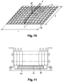
figure 10 est une vue en perspective d'une variante de réalisation de la paroi de fond, dont l'élément en relief comprend un réseau de nervures, - la
figure 11 est une vue générale en coupe d'un pack batterie comprenant une poche de gel en guise d'élément en relief.
- the
figure 1 is a perspective view from below of a battery pack according to one embodiment of the invention, in its closed case and mounted under a vehicle, - the
figure 2 is a partial cross-sectional and exploded view of the battery pack of thefigure 1 , - the
figure 3 is a perspective view of the battery pack whose case has been opened, - the
figure 4 is a view similar to thefigure 3 an electrical module stage having been removed, - the
figure 5 is a perspective view from above of the open case completely emptied of its contents, - the
figure 6 is a perspective view from above of the open housing containing a thermoregulatory plate, - the
figure 7 is a schematic view of assembled elements of a stage of the battery pack, - the
figure 8 is a diagrammatic view from below and on a larger scale of a portion of the thermoregulatory plate and its zones in contact with the bottom wall of the housing, - the
figure 9 is a schematic sectional view along IX-IX of a portion of the bottom wall corresponding to the portion of the thermoregulatory plate shown in FIG.figure 8 , - the
figure 10 is a perspective view of an alternative embodiment of the bottom wall, the raised element comprises a network of ribs, - the
figure 11 is a general sectional view of a battery pack comprising a gel pocket as a raised element.
Sur la
Le plancher 3 peut être réalisé en polypropylène.The
Cet agencement du pack batterie 1 sous un plancher 3 n'est qu'un exemple qui ne présente aucun caractère limitatif.This arrangement of the battery pack 1 under a
Le pack batterie 1, mieux visible sur l'éclaté de la
Les grandes faces latérales 11, respectivement 13, de la moitié supérieure 7a, respectivement inférieure 7b, comportent des pattes de fixation 15, respectivement 17, pour la fixation du boîtier 7 au plancher 3.The large lateral faces 11, respectively 13, of the
Sur l'éclaté de la
L'invention n'est pas limitée à ce mode de réalisation et le boîtier pourrait ne contenir qu'un seul étage, ou au contraire plus de deux étages.The invention is not limited to this embodiment and the housing could contain only one floor, or on the contrary more than two floors.
On va maintenant décrire l'étage E1. L'étage E2 contient les mêmes éléments, référencés par les mêmes numéros et le signe '.We will now describe the stage E1. The stage E2 contains the same elements, referenced by the same numbers and the sign '.
Comme on le voit mieux sur la
Dans un module 19-1 (respectivement 19-2, 19-3, 19-4, 19-5), le maintien des cellules entre elles est assuré par des flancs 23-1 (respectivement 23-2, 23-3, 23-4, 23-5, les flancs étant désignés de façon générique par la référence 23) placés contre les deux petites faces d'extrémité du parallélépipède et reliés entre eux par quatre tirants 25 (deux par grande face du module parallélépipédique). Les cinq modules sont maintenus sensiblement dans un même plan lorsqu'ils sont juxtaposés pour former un étage du boîtier.In a module 19-1 (respectively 19-2, 19-3, 19-4, 19-5), the cells are held together by flanks 23-1 (respectively 23-2, 23-3, 23). -4, 23-5, the flanks being designated generically by the reference 23) placed against the two small end faces of the parallelepiped and interconnected by four tie rods 25 (two per large face of the parallelepiped module). The five modules are held substantially in the same plane when they are juxtaposed to form a floor of the housing.
Comme on le voit sur la
Ainsi assemblés, les modules électriques 19 présentent les fonds de leurs cellules 21 sensiblement dans un même plan inférieur, formant le plafond de l'espace 31.Thus assembled, the electric modules 19 present the bottoms of their cells 21 substantially in the same lower plane, forming the ceiling of the
Une plaque thermorégulatrice 33, selon l'exemple de réalisation rectangulaire, vient se placer sous tous les fonds des cellules 21 de l'étage. Elle est donc ici commune aux cinq modules 19. Dans une variante, chaque module 19-1 à 19-5 pourrait posséder sa propre plaque. La plaque thermorégulatrice 33 est dimensionnée pour se loger dans l'espace 31. Elle est réalisée en aluminium et possède, le long de ses grands côtés, deux canaux principaux 35, prolongés par des tubes 37 de transport de fluide caloporteur dont chacun débouche dans un orifice du boîtier 7 visible sur la
Comme illustré sur la
Sur la plaque thermorégulatrice 33, un film thermoconducteur 43 (le film 43' de l'étage E2 est mieux visible sur la
Les flancs 23 possèdent des rebords inférieurs 45, respectivement supérieurs 47, qui permettent leur fixation, grâce par exemple à des vis 49, à une paroi de séparation 53 qui constitue, pour l'étage supérieur E1, une paroi de fond. La paroi 53 est mieux visible sur la
Les parois 53 et 53' sont, au sens de l'invention, des parois destinées à se trouver contre la plaque thermorégulatrice 33, 33' d'un module. Le boîtier comprend deux espaces intérieurs (non référencés), à savoir un par étage, dont chacun est destiné à contenir un module 19 constitué d'un ensemble de plusieurs cellules 21 électriques.The
Dans la suite de la description, la face intérieure d'une paroi 53 ou 53' désignera la face de cette paroi tournée vers l'espace intérieur contenant le module 19 interagissant avec la plaque thermorégulatrice 33, 33' se trouvant en contact avec ladite paroi.In the following description, the inner face of a
On voit mieux, sur le schéma en coupe de la
En particulier, on voit que la paroi 53 comporte un réseau de nervures 55 croisées et perpendiculaires sur sa face intérieure, au droit de la surface de la plaque thermorégulatrice 33 comprise entre ses canaux principaux 35.In particular, it can be seen that the
Bien que cela soit peu perceptible sur les figures en raison de la relativement faible variation de hauteur entre elles, les nervures 55 sont agencées en un réseau de nervures croisées inscrit dans une enveloppe bombée vers l'intérieur du boîtier et constituent, au sens de l'invention, un élément en relief présentant une convexité vers l'intérieur du boîtier.Although this is hardly perceptible in the figures because of the relatively small variation in height between them, the
De façon plus précise, L étant la plus grande dimension de la paroi, ici sa longueur puisque la paroi est rectangulaire, et I étant sa deuxième plus grande dimension, ici sa largeur, l'enveloppe dans laquelle sont inscrites les nervures 55 est bombée uniquement dans un plan normal à la paroi et parallèle à la direction de sa largeur I. Autrement dit, en section transversale parallèle à la direction de la longueur L, les nervures 55 ont la même hauteur sur toute la longueur L, mais cette hauteur varie en fonction de la section considérée et est maximale sur l'axe de symétrie centrale X de la paroi.More specifically, L being the largest dimension of the wall, here its length since the wall is rectangular, and I being its second largest dimension, here its width, the envelope in which are inscribed the
Dans l'exemple de ce mode de réalisation, la hauteur maximale de la convexité, c'est-à-dire la variation de hauteur entre le point le plus bas et le point le plus haut du réseau de nervures 55 est de 1,5% de la largeur I (qui est la plus petite des deux plus grandes dimensions L et I de la paroi 53).In the example of this embodiment, the maximum height of the convexity, that is to say the height variation between the lowest point and the highest point of the network of
Le réseau de nervures 55 est bordé, sur chacun de ses deux grands côtés longitudinaux, par un évidement 57 de profondeur d dimensionné pour accueillir les canaux principaux 35 de la plaque thermorégulatrice 33.The network of
Le long de chaque évidement 57, des appuis 59 parallèles à la direction de la largeur I servent de siège aux rebords inférieurs 45 des flancs 23. Certains de ces appuis 59 incorporent une cheminée de serrage 60 qui est alignée avec un orifice 44 des rebords inférieurs 45 des flancs 23. Chaque rebord 45 comporte deux orifices 44 et s'étend sur une longueur correspondant à six appuis 59 (numérotés dans ce qui suit premier à sixième, dans le sens de la longueur), en ne couvrant entièrement que les deuxième à cinquième appuis 59, tandis qu'il ne couvre que la moitié de chacun des première et sixième appuis 59, chacun de ces deux appuis recevant, sur son autre moitié, le flanc voisin du flan 23 considéré.Along each
Les cheminées de serrage 60 déterminent la direction de serrage, qui est donc ici, comme ce sera souvent le cas, perpendiculaire au plan général de la paroi 53.The clamping
Comme cela est mieux visible sur l'agrandissement de la
Grâce à la forme convexe de l'enveloppe des nervures 55, la déformation de la paroi de fond 53 lors du serrage, potentiellement de plus en plus marquée à mesure qu'on s'approche de l'axe de symétrie X de cette paroi 53, est compensée par une hauteur accrue des nervures à mesure qu'on s'approche de cet axe.Thanks to the convex shape of the envelope of the
Ainsi, dans un étage donné, on trouve l'empilement des éléments suivants :
- des cellules 21, 21' rassemblées en modules 19, 19',
une plaque thermorégulatrice 33, 33',une paroi 53, 53' serrée contre les modules par des moyens de serrage.
- cells 21, 21 'assembled in modules 19, 19',
- a
thermoregulatory plate 33, 33 ', - a
wall 53, 53 'clamped against the modules by clamping means.
Sur la
On désigne ces zones par l'expression « zones de contact ».These zones are referred to as "contact zones".
Cette pression résulte de la mise en contact des zones les plus hautes de la paroi de fond 53.This pressure results from the contacting of the highest zones of the
La matérialisation des zones de contact peut être obtenue en pratique par le dépôt d'une poudre colorée sur les bords supérieurs libres des nervures 55. Lors du serrage de la plaque thermorégulatrice 33 par la paroi de fond 53, cette poudre se transfère sur la plaque 33 pour donner le motif représenté à la
Comme on le voit sur cette
Ainsi, dans le disque 61, on trouve le point le plus haut 63, dans le disque 65, on trouve le point le plus haut 67, dans le disque 69, on trouve le point le plus haut 71, dans le disque 73, on trouve le point le plus haut 75, et dans le disque 77, on trouve le point le plus haut 79.Thus, in the
En outre, la paroi de fond 53 possède un point le plus haut 81.In addition, the
Chacun de ces points les plus hauts 63, 67, 71, 75, 79 et 81 se trouve au sommet d'une nervure 55 du réseau de nervures, tel que représenté en section sur la
On voit aussi sur cette figure que les sommets des nervures 55 peuvent être arrondis en section, ce qui a pour effet de réduire la surface de chaque zone de contact. Toutefois, en raison de l'aptitude à la déformation (élastique ou plastique) de la matière constituant les nervures, le sommet de chaque nervure peut s'écraser de sorte que les zones de contact ne se limitent pas à des lignes.We also see in this figure that the vertices of the
La plaque thermorégulatrice 33 est donc maintenue en contact avec les cellules 21 de manière optimale sur toute sa surface, étant entendu qu'on entend par de « manière optimale » le fait que le contact entre ces deux pièces s'établisse au moins en certaines zones suffisamment rapprochées pour que deux points voisins ne soient pas distants de plus de la distance D, ou, en d'autres termes, pour que tout cercle de diamètre D dessiné sur la plaque thermorégulatrice 33 contienne au moins deux de ces zones de contact, ce qui traduit une densité assez élevée et régulière de points de contact entre la plaque et les cellules.The
Dans le mode de réalisation de la
Ce réseau de nervures 90 est convexe, au sens où les sommets des nervures 90 sont inscrits dans une enveloppe bombée vers le haut (par rapport à la figure).This network of
La convexité de l'enveloppe s'exprime dans les deux directions de L et de I, avec une hauteur maximale, c'est-à-dire une variation de hauteur entre le point le plus bas et le point le plus haut, avantageusement de 2% de I, bien que, sur la représentation schématique de la
On peut vérifier la convexité du réseau de nervures en procédant comme suit.
- 1°) On fixe un diamètre D fonction des dimensions de la plaque thermorégulatrice, qui est ici supposée avoir la même largeur I et la même longueur L que la paroi. On prend ici D = 50 mm.
- 2°) On détecte le point le plus haut H de la paroi, selon la direction de serrage indiquée par la flèche S pointant vers le haut.
- 3°) On trace un quadrillage à maille carrée de côté D/√2 ayant une intersection confondue avec le point H. A chaque intersection du maillage, on trace un cercle de diamètre D.
- 4°) Dans chaque disque de diamètre D, on cherche le point le plus haut Hi.
- 5°) On prend un plan P passant par le point H et parallèle à la direction S et à la direction de la longueur L.
- 6°) On projette orthogonalement sur le plan P les points Hi les plus hauts obtenus à l'étape 3 qui sont situés à une distance de ce plan inférieure à D, pour obtenir des points hi.
- 7°) On vérifie que, sur le plan P, la ligne brisée passant par tous les points hi et par le point H est convexe.
- 8°) On fait tourner le plan P autour de la direction S et on répète les étapes 5 et 6.
- 1 °) One fixes a diameter D function of the dimensions of the thermoregulatory plate, which is here supposed to have the same width I and the same length L as the wall. Here we take D = 50 mm.
- 2 °) One detects the highest point H of the wall, according to the direction of tightening indicated by the arrow S pointing upwards.
- 3 °) One draws a grid with square mesh of side D / √2 having an intersection confused with the point H. At each intersection of the mesh, one draws a circle of diameter D.
- 4 °) In each disk of diameter D, one looks for the highest point H i .
- 5 °) Take a plane P passing through the point H and parallel to the direction S and to the direction of the length L.
- 6 °) One projects orthogonally on the plane P the highest points H i obtained in
step 3 which are located at a distance of this plane lower than D, to obtain points h i . - 7 °) One verifies that, on the plane P, the broken line passing by all the points h i and by the point H is convex.
- 8 °) The plane P is rotated around the direction S and steps 5 and 6 are repeated.
Une méthode alternative consiste à rechercher s'il existe une direction « de non convexité » selon laquelle tous les points obtenus à l'étape 3 présents dans un plan parallèle à cette direction ont la même hauteur. Si tel est le cas, on exécute les étapes 5 et 6 en choisissant un plan P parallèle à S et perpendiculaire à la direction « de non convexité », en faisant balayer toute la paroi au plan P par translation de pas D.An alternative method consists in finding out if there is a "non-convexity" direction according to which all the points obtained in
Dans le mode de réalisation de la
Là encore, la pression transmise est la même en tout point de la plaque thermorégulatrice 53, indépendamment de la déformation subie par la paroi de fond 101 lors du serrage des vis 49 assujettissant les flancs 23 à la paroi de fond 101.Again, the transmitted pressure is the same at any point of the heat-
Il est bien entendu que les exemples décrits ci-dessus ne sont donnés qu'à titre indicatif et qu'ils ne pourront être interprétés comme limitant la portée des revendications.It is understood that the examples described above are given for information only and that they can not be interpreted as limiting the scope of the claims.
Claims (20)
- Housing (7) of a battery pack (1) for a motor vehicle, comprising an inner space designed to contain at least one module (19), consisting of a set of several electric cells (21), associated with a thermoregulating plate (33), the housing having at least one wall (53, 53') designed to rest against the thermoregulating plate (33) when the module (19) is present in the housing, this housing being characterised in that it comprises fastening means (23, 49, 60) for fastening a module (19) against said wall (53, 53') and in that said wall (53, 53') comprises, on its inner face turned towards the thermoregulating plate (33), an element in relief (55, 90) inscribed in a volume having a convexity turned towards the inner space of the housing.
- Housing according to claim 1, of which the wall (53, 53') is made of a thermoplastic plastic material or of a thermosetting plastic material or of a mixture of the two materials or of moulded aluminium or of cast aluminium.
- Housing according to claim 1 or 2, wherein the fastening means consist of closing means for closing the housing, comprising a bottom and a lid, said bottom or said lid comprising the wall (53') designed to rest against the thermoregulating plate (33).
- Housing according to claim 1 or 2, wherein the fastening means consist of fixation means for directly fixing the module (19) on the wall (53, 53'), for example by using flanks (23) fastened to two opposite lateral faces of the module (19).
- Housing according to any of the preceding claims, wherein the fastening means define a fastening direction (S) and the convexity of the element in relief is defined by the following features, the heights being measured in the fastening direction:- presence of at least one highest point H (81) of the element in relief,- presence of at least one projection plane P passing through the highest point H (81) and parallel to the fastening direction (S), this plane being such that in any area obtained by projection on the element in relief of a disc (61, 65, 69, 73, 77) of predetermined diameter located in a second plane P' perpendicular to the fastening direction and passing through the highest point (81) of the element in relief, there is at least one highest point Hi (63, 67, 71, 75, 79) whose orthogonal projection hi on the plane of projection has a height on the plane of projection which decreases with the distance between said projection and the highest point H (81).
- Housing according to any of the preceding claims, wherein the element in relief comprises a solid (55, 90) having a convexity turned towards the inside of the housing.
- Housing according to claim 6, wherein the solid comprises a net of ribs (55) projecting from the inner face of the wall and inscribed in an envelope doming towards the inside of the housing.
- Housing according to claim 7, wherein the ribs (55) of the net of ribs are integrally moulded with the wall (53, 53').
- Housing according to claim 6, wherein the solid is obtained by giving the wall a shape protruding towards the inside of the housing.
- Housing according to claim 6, wherein the solid comprises a set of studs formed on the bottom wall and each contact area is the top of a stud.
- Housing according to any of the preceding claims, wherein the element in relief comprises a block of deformable material having an outer face of a shape protruding towards the inside of the housing.
- Housing according to any of the preceding claims, wherein the wall (53, 53') has a first large dimension (L) along a first direction, a second large dimension (I) along a second direction perpendicular to the first direction, and wherein the maximum height of the convexity, i.e. the variation of the height between the highest point and the lowest point of the element in relief, is between 0.2% and 0.5% of one of these two large dimensions of the wall, preferably of the smaller one of these two large dimension, and preferably between 0.1% and 2%, and preferably between 0.2% and 0.5%.
- Battery pack for a motor vehicle, comprising a housing containing at least one module (29), consisting of a set of several electric cells (21), associated with a thermoregulating plate (33), the housing having at least one wall (53, 53') designed to rest against the thermoregulating plate (33) of the module (29), characterised in that this wall (53, 53') comprises, on its inner face turned towards the thermoregulating plate (33), an element in relief (55, 90, 99) arranged and dimensioned to transmit to the thermoregulating plate (33) a fastening pressure exerted by the wall (53, 53'), this fastening pressure being such that the element in relief (55, 90, 99) and the thermoregulating plate (33) remain in contact with each other, notwithstanding a possible deformation of the wall (53, 53') caused by the fastening, this contact occurring at least at points of the element in relief (55, 90, 99), which are distributed such that any disc of diameter of 20 to 80 mm, preferably 30 to 60 mm, drawn by projection on the thermoregulating plate (33), contains at least two of these points.
- Battery pack according to claim 13, wherein each cell (12) comprises a rigid envelope and the envelopes of the cells of a same module (19) makes up a rigid block by being pressed against each other along a transverse direction with their coplanar bottoms.
- Battery pack according to claim 13 or 14, wherein the rigid envelopes of the cells (21) have a prismatic shape, with rectangular bases.
- Battery pack according to any of claims 13 to 15, wherein several modules (19) share the same thermoregulating plate (33).
- Battery pack according to any of claims 13 to 15, wherein each module has its own thermoregulating plate.
- Battery pack according to any of claims 13 to 17, wherein the element in relief comprises a pocket (99) of an incompressible liquid or gel, capable of uniformly and isotropically transmitting the pressure which it is subjected to and results from the force fastening the wall against the plate.
- Battery pack according to claim 18, wherein the liquid or the gel presents heat isolation properties.
- Battery pack according to claim 18 or 19, wherein the liquid or the gel presents electrical isolation properties.
Applications Claiming Priority (2)
| Application Number | Priority Date | Filing Date | Title |
|---|---|---|---|
| FR1250960A FR2986190B1 (en) | 2012-02-01 | 2012-02-01 | CASE FOR ELECTRICAL MODULE OF A BATTERY PACK FOR MOTOR VEHICLE AND BATTERY PACK FOR MOTOR VEHICLE |
| PCT/FR2013/050216 WO2013114054A1 (en) | 2012-02-01 | 2013-02-01 | Housing for an electrical module of a battery pack for a motor vehicle, and associated battery pack |
Publications (2)
| Publication Number | Publication Date |
|---|---|
| EP2809537A1 EP2809537A1 (en) | 2014-12-10 |
| EP2809537B1 true EP2809537B1 (en) | 2016-04-20 |
Family
ID=47754803
Family Applications (1)
| Application Number | Title | Priority Date | Filing Date |
|---|---|---|---|
| EP13706614.8A Active EP2809537B1 (en) | 2012-02-01 | 2013-02-01 | Housing for an electric module of a battery pack for a motor vehicle and corresponding battery pack |
Country Status (9)
| Country | Link |
|---|---|
| US (1) | US9818994B2 (en) |
| EP (1) | EP2809537B1 (en) |
| JP (1) | JP6188725B2 (en) |
| KR (1) | KR101986235B1 (en) |
| CN (1) | CN104220286B (en) |
| FR (1) | FR2986190B1 (en) |
| MX (1) | MX2014009376A (en) |
| RU (1) | RU2014135407A (en) |
| WO (1) | WO2013114054A1 (en) |
Families Citing this family (37)
| Publication number | Priority date | Publication date | Assignee | Title |
|---|---|---|---|---|
| JP5811168B2 (en) * | 2013-12-25 | 2015-11-11 | トヨタ自動車株式会社 | Battery mounting structure for vehicles |
| DE102014108160A1 (en) * | 2014-06-11 | 2015-12-17 | Dr. Ing. H.C. F. Porsche Aktiengesellschaft | Underbody unit for a motor vehicle |
| US9825343B2 (en) * | 2014-09-30 | 2017-11-21 | Johnson Controls Technology Company | Battery module passive thermal management features and positioning |
| US9634364B2 (en) * | 2014-10-28 | 2017-04-25 | Ford Global Technologies, Llc | Support structure for traction battery assembly with integrated thermal plate |
| US10347953B2 (en) * | 2014-12-02 | 2019-07-09 | Ford Global Technologies, Llc | Battery module having side compression structure with heat exchanger |
| KR101776853B1 (en) * | 2015-06-30 | 2017-09-12 | 인지컨트롤스 주식회사 | Battery pack |
| US10497997B2 (en) * | 2016-03-14 | 2019-12-03 | Ford Global Technologies, Llc | Assembly and method to maintain clearance to a thermal fin within a battery assembly |
| US10170810B2 (en) * | 2016-04-18 | 2019-01-01 | Lg Chem, Ltd. | Thermally conductive base member and method of assembling the thermally conductive base member |
| US9979058B2 (en) * | 2016-04-20 | 2018-05-22 | Ford Global Technologies, Llc | Battery thermal energy transfer assembly and method |
| CN109314200B (en) * | 2016-06-29 | 2022-04-08 | 松下知识产权经营株式会社 | Battery module |
| DE102017107203B4 (en) * | 2017-04-04 | 2021-04-22 | Hoppecke Batterien Gmbh & Co. Kg | Traction battery |
| US10109901B2 (en) * | 2016-07-22 | 2018-10-23 | Ford Global Technologies, Llc | Battery thermal interface material installation assembly and method |
| DE102016009212A1 (en) * | 2016-08-01 | 2018-02-01 | Audi Ag | Battery module and battery |
| CN113690521A (en) * | 2016-11-16 | 2021-11-23 | 奥动新能源汽车科技有限公司 | Vehicle-mounted power battery box |
| KR102155330B1 (en) * | 2016-11-29 | 2020-09-11 | 주식회사 엘지화학 | Air cooling type secondary battery module |
| KR102196263B1 (en) * | 2016-11-30 | 2020-12-29 | 주식회사 엘지화학 | Battery Pack Having Cooling Structure with Improved Stability for Use of Liquid Coolant |
| JP6813348B2 (en) * | 2016-12-14 | 2021-01-13 | 株式会社Subaru | Car vehicle |
| CA3047021A1 (en) * | 2016-12-19 | 2018-06-28 | Dana Canada Corporation | Battery cooler support architecture |
| WO2018149762A1 (en) * | 2017-02-17 | 2018-08-23 | Mubea Carbo Tech Gmbh | Battery structure and protector |
| US10971777B2 (en) * | 2017-04-11 | 2021-04-06 | Ford Global Technologies, Llc | Traction battery support assembly and method |
| JP6929464B2 (en) * | 2017-12-26 | 2021-09-01 | 信越ポリマー株式会社 | Heat dissipation structure and battery with it |
| KR102526107B1 (en) | 2018-04-06 | 2023-04-26 | 씨피에스 테크놀로지 홀딩스 엘엘씨 | Thermal Management System for Battery Modules |
| DE102018206102A1 (en) * | 2018-04-20 | 2019-10-24 | Thyssenkrupp Ag | Underride protection arrangement for a vehicle battery assembly, vehicle battery assembly, method for producing an underrun protection arrangement, method for producing a vehicle battery assembly |
| DE102018216113A1 (en) * | 2018-09-21 | 2020-03-26 | Audi Ag | Method for arranging at least one battery module in at least part of a battery housing and arrangement device |
| KR20200074320A (en) * | 2018-12-14 | 2020-06-25 | 현대자동차주식회사 | Battery pack |
| DE102019110007B3 (en) | 2019-04-16 | 2020-08-06 | Bayerische Motoren Werke Aktiengesellschaft | Battery arrangement for a vehicle comprising a carrier device with two receiving spaces and a vehicle |
| CN114072962A (en) * | 2019-04-18 | 2022-02-18 | Cps 科技控股有限公司 | Fixing of heat sinks by melting of plastic |
| KR102053033B1 (en) | 2019-05-17 | 2019-12-06 | (주)경도시스템 | Integrated type storage device for battery pack |
| KR20200132628A (en) | 2019-09-10 | 2020-11-25 | (주)경도시스템 | Integrated type storage device for battery pack |
| KR20210043990A (en) * | 2019-10-14 | 2021-04-22 | 주식회사 엘지화학 | Battery pack and manufacturing method thereof |
| KR102424745B1 (en) | 2019-12-12 | 2022-07-25 | 한국광기술원 | Battery rack device |
| CN111312956B (en) * | 2020-02-27 | 2022-10-11 | 爱驰汽车有限公司 | Battery pack, battery pack manufacturing device, and battery pack manufacturing method |
| US11588199B2 (en) * | 2020-03-10 | 2023-02-21 | Karma Automotive Llc | Vehicle battery system |
| US11545716B2 (en) * | 2020-10-26 | 2023-01-03 | Ford Global Technologies, Llc | Traction battery upper-tier battery array support assembly and support method |
| JP2022091254A (en) * | 2020-12-09 | 2022-06-21 | 本田技研工業株式会社 | Battery case structure |
| US11961987B2 (en) * | 2022-09-06 | 2024-04-16 | Harbinger Motors Inc. | Battery modules with casted module enclosures and methods of fabricating thereof |
| DE102022127777A1 (en) | 2022-10-20 | 2024-04-25 | Friedrich Boysen GmbH & Co KG. | BATTERY CASE |
Family Cites Families (8)
| Publication number | Priority date | Publication date | Assignee | Title |
|---|---|---|---|---|
| JP5098544B2 (en) * | 2007-09-28 | 2012-12-12 | 三菱自動車工業株式会社 | Battery unit |
| PE20110470A1 (en) | 2008-06-27 | 2011-07-15 | Proterra Inc | BATTERY SYSTEMS AND METHODS FOR VEHICLES |
| JP2010238554A (en) * | 2009-03-31 | 2010-10-21 | Toyota Motor Corp | Holder of power storage element |
| DE102009040814A1 (en) * | 2009-09-10 | 2011-03-17 | Behr Gmbh & Co. Kg | Method for producing an energy storage holder for a vehicle |
| DE102009058070A1 (en) | 2009-12-14 | 2011-06-16 | Behr Gmbh & Co. Kg | Cooling device for a battery module |
| DE102009058809A1 (en) * | 2009-12-18 | 2011-06-22 | Valeo Klimasysteme GmbH, 96476 | Cooling device for a vehicle drive battery and vehicle drive battery assembly with cooling device |
| JP2011175743A (en) * | 2010-02-23 | 2011-09-08 | Sanyo Electric Co Ltd | Power source apparatus, and vehicle equipped with the same |
| WO2012147801A1 (en) * | 2011-04-27 | 2012-11-01 | 三洋電機株式会社 | Power supply device and vehicle equipped with power supply device |
-
2012
- 2012-02-01 FR FR1250960A patent/FR2986190B1/en not_active Expired - Fee Related
-
2013
- 2013-02-01 CN CN201380018847.6A patent/CN104220286B/en active Active
- 2013-02-01 US US14/375,901 patent/US9818994B2/en active Active
- 2013-02-01 EP EP13706614.8A patent/EP2809537B1/en active Active
- 2013-02-01 KR KR1020147024474A patent/KR101986235B1/en active IP Right Grant
- 2013-02-01 JP JP2014555290A patent/JP6188725B2/en active Active
- 2013-02-01 RU RU2014135407A patent/RU2014135407A/en not_active Application Discontinuation
- 2013-02-01 MX MX2014009376A patent/MX2014009376A/en unknown
- 2013-02-01 WO PCT/FR2013/050216 patent/WO2013114054A1/en active Application Filing
Also Published As
| Publication number | Publication date |
|---|---|
| WO2013114054A1 (en) | 2013-08-08 |
| JP6188725B2 (en) | 2017-08-30 |
| US9818994B2 (en) | 2017-11-14 |
| KR101986235B1 (en) | 2019-06-07 |
| FR2986190A1 (en) | 2013-08-02 |
| JP2015510230A (en) | 2015-04-02 |
| EP2809537A1 (en) | 2014-12-10 |
| CN104220286B (en) | 2017-03-08 |
| MX2014009376A (en) | 2015-01-14 |
| FR2986190B1 (en) | 2015-02-27 |
| KR20140128396A (en) | 2014-11-05 |
| RU2014135407A (en) | 2016-03-27 |
| US20150249238A1 (en) | 2015-09-03 |
| CN104220286A (en) | 2014-12-17 |
| WO2013114054A9 (en) | 2014-08-21 |
Similar Documents
| Publication | Publication Date | Title |
|---|---|---|
| EP2809537B1 (en) | Housing for an electric module of a battery pack for a motor vehicle and corresponding battery pack | |
| EP3776686B1 (en) | Battery unit with integrated heat exchange zones | |
| EP2875547B1 (en) | Battery module having compressed cells | |
| EP1221728B1 (en) | A resealable valve and electrochemical generator comprising said valve | |
| EP2751820B1 (en) | Connector between two cylindricals energy storage cells | |
| WO2013113691A1 (en) | Positioning spacer, energy storage module using said spacer and method for assembling the module | |
| FR2988915A3 (en) | Module structure for housing lithium-ion battery cells in battery module in e.g. electric vehicle, has case arranged to form spacing between adjacent walls perpendicular to basic wall, where thickness of basic wall is equal to that of cells | |
| WO2012168648A1 (en) | Device for cooling cylindrical electrochemical cells | |
| FR2988914A3 (en) | Module structure for housing Lithium-ion battery cells in battery module in e.g. electric vehicle, has structure element formed such that spacing is formed between basic walls, where flexible envelope is placed between basic walls | |
| EP3316350B1 (en) | Electrical connection piece for accumulator | |
| EP2751822B1 (en) | A long life electric energy storage unit comprising an inter-connector | |
| EP0522981A1 (en) | Monobloc accumulator battery | |
| EP4327395A1 (en) | Sealed electric battery housing | |
| WO2016156365A1 (en) | Battery module, in particular for a motor vehicle, and corresponding heat exchanger for a battery module | |
| FR3092527A1 (en) | Box for electrical energy storage device for motor vehicle | |
| EP3707771B1 (en) | Structure for heat treatment of an electrical storage device for a motor vehicle | |
| FR3056856B1 (en) | THERMOELECTRIC ELEMENT, MODULE AND GENERATOR FOR A THERMAL MOTOR VEHICLE AND METHOD OF MANUFACTURING THE MODULE | |
| EP4164014A1 (en) | Battery pack architecture | |
| FR3081544A1 (en) | COLLECTOR BOX FOR A HEAT EXCHANGER | |
| FR3116655A1 (en) | Pocket-type electrochemical cell for an energy storage device | |
| WO2018060613A1 (en) | Unitary tubular module for combustion engine automotive vehicle, and thermoelectric generator including a plurality of these modules | |
| FR2780814A1 (en) | FIXABLE BEAM RECHARGEABLE ACCUMULATOR |
Legal Events
| Date | Code | Title | Description |
|---|---|---|---|
| PUAI | Public reference made under article 153(3) epc to a published international application that has entered the european phase |
Free format text: ORIGINAL CODE: 0009012 |
|
| 17P | Request for examination filed |
Effective date: 20140731 |
|
| AK | Designated contracting states |
Kind code of ref document: A1 Designated state(s): AL AT BE BG CH CY CZ DE DK EE ES FI FR GB GR HR HU IE IS IT LI LT LU LV MC MK MT NL NO PL PT RO RS SE SI SK SM TR |
|
| AX | Request for extension of the european patent |
Extension state: BA ME |
|
| DAX | Request for extension of the european patent (deleted) | ||
| REG | Reference to a national code |
Ref country code: DE Ref legal event code: R079 Ref document number: 602013006720 Country of ref document: DE Free format text: PREVIOUS MAIN CLASS: B60K0001040000 Ipc: B60K0001000000 |
|
| RIC1 | Information provided on ipc code assigned before grant |
Ipc: H01M 10/617 20140101ALI20150901BHEP Ipc: H01M 10/613 20140101ALI20150901BHEP Ipc: H01M 2/10 20060101ALI20150901BHEP Ipc: H01M 10/6554 20140101ALI20150901BHEP Ipc: H01M 10/6551 20140101ALI20150901BHEP Ipc: B60K 1/04 20060101ALI20150901BHEP Ipc: F28F 3/12 20060101ALI20150901BHEP Ipc: B60K 1/00 20060101AFI20150901BHEP Ipc: H01M 10/625 20140101ALI20150901BHEP Ipc: F28F 13/00 20060101ALI20150901BHEP |
|
| GRAP | Despatch of communication of intention to grant a patent |
Free format text: ORIGINAL CODE: EPIDOSNIGR1 |
|
| INTG | Intention to grant announced |
Effective date: 20151009 |
|
| GRAS | Grant fee paid |
Free format text: ORIGINAL CODE: EPIDOSNIGR3 |
|
| GRAA | (expected) grant |
Free format text: ORIGINAL CODE: 0009210 |
|
| AK | Designated contracting states |
Kind code of ref document: B1 Designated state(s): AL AT BE BG CH CY CZ DE DK EE ES FI FR GB GR HR HU IE IS IT LI LT LU LV MC MK MT NL NO PL PT RO RS SE SI SK SM TR |
|
| REG | Reference to a national code |
Ref country code: GB Ref legal event code: FG4D Free format text: NOT ENGLISH |
|
| REG | Reference to a national code |
Ref country code: CH Ref legal event code: EP |
|
| REG | Reference to a national code |
Ref country code: AT Ref legal event code: REF Ref document number: 792008 Country of ref document: AT Kind code of ref document: T Effective date: 20160515 |
|
| REG | Reference to a national code |
Ref country code: IE Ref legal event code: FG4D Free format text: LANGUAGE OF EP DOCUMENT: FRENCH |
|
| REG | Reference to a national code |
Ref country code: DE Ref legal event code: R096 Ref document number: 602013006720 Country of ref document: DE |
|
| REG | Reference to a national code |
Ref country code: DE Ref legal event code: R082 Ref document number: 602013006720 Country of ref document: DE Representative=s name: MAIWALD PATENTANWALTSGESELLSCHAFT MBH, DE Ref country code: DE Ref legal event code: R082 Ref document number: 602013006720 Country of ref document: DE Representative=s name: MAIWALD PATENTANWALTS- UND RECHTSANWALTSGESELL, DE |
|
| REG | Reference to a national code |
Ref country code: LT Ref legal event code: MG4D |
|
| REG | Reference to a national code |
Ref country code: AT Ref legal event code: MK05 Ref document number: 792008 Country of ref document: AT Kind code of ref document: T Effective date: 20160420 |
|
| REG | Reference to a national code |
Ref country code: NL Ref legal event code: MP Effective date: 20160420 |
|
| PG25 | Lapsed in a contracting state [announced via postgrant information from national office to epo] |
Ref country code: LT Free format text: LAPSE BECAUSE OF FAILURE TO SUBMIT A TRANSLATION OF THE DESCRIPTION OR TO PAY THE FEE WITHIN THE PRESCRIBED TIME-LIMIT Effective date: 20160420 Ref country code: PL Free format text: LAPSE BECAUSE OF FAILURE TO SUBMIT A TRANSLATION OF THE DESCRIPTION OR TO PAY THE FEE WITHIN THE PRESCRIBED TIME-LIMIT Effective date: 20160420 Ref country code: FI Free format text: LAPSE BECAUSE OF FAILURE TO SUBMIT A TRANSLATION OF THE DESCRIPTION OR TO PAY THE FEE WITHIN THE PRESCRIBED TIME-LIMIT Effective date: 20160420 Ref country code: NL Free format text: LAPSE BECAUSE OF FAILURE TO SUBMIT A TRANSLATION OF THE DESCRIPTION OR TO PAY THE FEE WITHIN THE PRESCRIBED TIME-LIMIT Effective date: 20160420 Ref country code: NO Free format text: LAPSE BECAUSE OF FAILURE TO SUBMIT A TRANSLATION OF THE DESCRIPTION OR TO PAY THE FEE WITHIN THE PRESCRIBED TIME-LIMIT Effective date: 20160720 |
|
| PG25 | Lapsed in a contracting state [announced via postgrant information from national office to epo] |
Ref country code: PT Free format text: LAPSE BECAUSE OF FAILURE TO SUBMIT A TRANSLATION OF THE DESCRIPTION OR TO PAY THE FEE WITHIN THE PRESCRIBED TIME-LIMIT Effective date: 20160822 Ref country code: ES Free format text: LAPSE BECAUSE OF FAILURE TO SUBMIT A TRANSLATION OF THE DESCRIPTION OR TO PAY THE FEE WITHIN THE PRESCRIBED TIME-LIMIT Effective date: 20160420 Ref country code: GR Free format text: LAPSE BECAUSE OF FAILURE TO SUBMIT A TRANSLATION OF THE DESCRIPTION OR TO PAY THE FEE WITHIN THE PRESCRIBED TIME-LIMIT Effective date: 20160721 Ref country code: SE Free format text: LAPSE BECAUSE OF FAILURE TO SUBMIT A TRANSLATION OF THE DESCRIPTION OR TO PAY THE FEE WITHIN THE PRESCRIBED TIME-LIMIT Effective date: 20160420 Ref country code: RS Free format text: LAPSE BECAUSE OF FAILURE TO SUBMIT A TRANSLATION OF THE DESCRIPTION OR TO PAY THE FEE WITHIN THE PRESCRIBED TIME-LIMIT Effective date: 20160420 Ref country code: LV Free format text: LAPSE BECAUSE OF FAILURE TO SUBMIT A TRANSLATION OF THE DESCRIPTION OR TO PAY THE FEE WITHIN THE PRESCRIBED TIME-LIMIT Effective date: 20160420 Ref country code: AT Free format text: LAPSE BECAUSE OF FAILURE TO SUBMIT A TRANSLATION OF THE DESCRIPTION OR TO PAY THE FEE WITHIN THE PRESCRIBED TIME-LIMIT Effective date: 20160420 Ref country code: HR Free format text: LAPSE BECAUSE OF FAILURE TO SUBMIT A TRANSLATION OF THE DESCRIPTION OR TO PAY THE FEE WITHIN THE PRESCRIBED TIME-LIMIT Effective date: 20160420 |
|
| PG25 | Lapsed in a contracting state [announced via postgrant information from national office to epo] |
Ref country code: IT Free format text: LAPSE BECAUSE OF FAILURE TO SUBMIT A TRANSLATION OF THE DESCRIPTION OR TO PAY THE FEE WITHIN THE PRESCRIBED TIME-LIMIT Effective date: 20160420 |
|
| REG | Reference to a national code |
Ref country code: DE Ref legal event code: R097 Ref document number: 602013006720 Country of ref document: DE |
|
| PG25 | Lapsed in a contracting state [announced via postgrant information from national office to epo] |
Ref country code: CZ Free format text: LAPSE BECAUSE OF FAILURE TO SUBMIT A TRANSLATION OF THE DESCRIPTION OR TO PAY THE FEE WITHIN THE PRESCRIBED TIME-LIMIT Effective date: 20160420 Ref country code: EE Free format text: LAPSE BECAUSE OF FAILURE TO SUBMIT A TRANSLATION OF THE DESCRIPTION OR TO PAY THE FEE WITHIN THE PRESCRIBED TIME-LIMIT Effective date: 20160420 Ref country code: SK Free format text: LAPSE BECAUSE OF FAILURE TO SUBMIT A TRANSLATION OF THE DESCRIPTION OR TO PAY THE FEE WITHIN THE PRESCRIBED TIME-LIMIT Effective date: 20160420 Ref country code: RO Free format text: LAPSE BECAUSE OF FAILURE TO SUBMIT A TRANSLATION OF THE DESCRIPTION OR TO PAY THE FEE WITHIN THE PRESCRIBED TIME-LIMIT Effective date: 20160420 Ref country code: DK Free format text: LAPSE BECAUSE OF FAILURE TO SUBMIT A TRANSLATION OF THE DESCRIPTION OR TO PAY THE FEE WITHIN THE PRESCRIBED TIME-LIMIT Effective date: 20160420 |
|
| REG | Reference to a national code |
Ref country code: FR Ref legal event code: PLFP Year of fee payment: 5 |
|
| PLBE | No opposition filed within time limit |
Free format text: ORIGINAL CODE: 0009261 |
|
| STAA | Information on the status of an ep patent application or granted ep patent |
Free format text: STATUS: NO OPPOSITION FILED WITHIN TIME LIMIT |
|
| PG25 | Lapsed in a contracting state [announced via postgrant information from national office to epo] |
Ref country code: SM Free format text: LAPSE BECAUSE OF FAILURE TO SUBMIT A TRANSLATION OF THE DESCRIPTION OR TO PAY THE FEE WITHIN THE PRESCRIBED TIME-LIMIT Effective date: 20160420 |
|
| 26N | No opposition filed |
Effective date: 20170123 |
|
| PG25 | Lapsed in a contracting state [announced via postgrant information from national office to epo] |
Ref country code: BE Free format text: LAPSE BECAUSE OF NON-PAYMENT OF DUE FEES Effective date: 20170228 Ref country code: SI Free format text: LAPSE BECAUSE OF FAILURE TO SUBMIT A TRANSLATION OF THE DESCRIPTION OR TO PAY THE FEE WITHIN THE PRESCRIBED TIME-LIMIT Effective date: 20160420 |
|
| PG25 | Lapsed in a contracting state [announced via postgrant information from national office to epo] |
Ref country code: MC Free format text: LAPSE BECAUSE OF FAILURE TO SUBMIT A TRANSLATION OF THE DESCRIPTION OR TO PAY THE FEE WITHIN THE PRESCRIBED TIME-LIMIT Effective date: 20160420 |
|
| REG | Reference to a national code |
Ref country code: CH Ref legal event code: PL |
|
| PG25 | Lapsed in a contracting state [announced via postgrant information from national office to epo] |
Ref country code: CH Free format text: LAPSE BECAUSE OF NON-PAYMENT OF DUE FEES Effective date: 20170228 Ref country code: LI Free format text: LAPSE BECAUSE OF NON-PAYMENT OF DUE FEES Effective date: 20170228 |
|
| REG | Reference to a national code |
Ref country code: IE Ref legal event code: MM4A |
|
| PG25 | Lapsed in a contracting state [announced via postgrant information from national office to epo] |
Ref country code: LU Free format text: LAPSE BECAUSE OF NON-PAYMENT OF DUE FEES Effective date: 20170201 |
|
| REG | Reference to a national code |
Ref country code: FR Ref legal event code: PLFP Year of fee payment: 6 |
|
| REG | Reference to a national code |
Ref country code: BE Ref legal event code: MM Effective date: 20170228 |
|
| PG25 | Lapsed in a contracting state [announced via postgrant information from national office to epo] |
Ref country code: IE Free format text: LAPSE BECAUSE OF NON-PAYMENT OF DUE FEES Effective date: 20170201 |
|
| PG25 | Lapsed in a contracting state [announced via postgrant information from national office to epo] |
Ref country code: MT Free format text: LAPSE BECAUSE OF FAILURE TO SUBMIT A TRANSLATION OF THE DESCRIPTION OR TO PAY THE FEE WITHIN THE PRESCRIBED TIME-LIMIT Effective date: 20160420 |
|
| PG25 | Lapsed in a contracting state [announced via postgrant information from national office to epo] |
Ref country code: AL Free format text: LAPSE BECAUSE OF FAILURE TO SUBMIT A TRANSLATION OF THE DESCRIPTION OR TO PAY THE FEE WITHIN THE PRESCRIBED TIME-LIMIT Effective date: 20160420 |
|
| PG25 | Lapsed in a contracting state [announced via postgrant information from national office to epo] |
Ref country code: HU Free format text: LAPSE BECAUSE OF FAILURE TO SUBMIT A TRANSLATION OF THE DESCRIPTION OR TO PAY THE FEE WITHIN THE PRESCRIBED TIME-LIMIT; INVALID AB INITIO Effective date: 20130201 |
|
| PG25 | Lapsed in a contracting state [announced via postgrant information from national office to epo] |
Ref country code: BG Free format text: LAPSE BECAUSE OF FAILURE TO SUBMIT A TRANSLATION OF THE DESCRIPTION OR TO PAY THE FEE WITHIN THE PRESCRIBED TIME-LIMIT Effective date: 20160420 |
|
| PG25 | Lapsed in a contracting state [announced via postgrant information from national office to epo] |
Ref country code: CY Free format text: LAPSE BECAUSE OF FAILURE TO SUBMIT A TRANSLATION OF THE DESCRIPTION OR TO PAY THE FEE WITHIN THE PRESCRIBED TIME-LIMIT Effective date: 20160420 |
|
| PG25 | Lapsed in a contracting state [announced via postgrant information from national office to epo] |
Ref country code: MK Free format text: LAPSE BECAUSE OF FAILURE TO SUBMIT A TRANSLATION OF THE DESCRIPTION OR TO PAY THE FEE WITHIN THE PRESCRIBED TIME-LIMIT Effective date: 20160420 |
|
| PG25 | Lapsed in a contracting state [announced via postgrant information from national office to epo] |
Ref country code: TR Free format text: LAPSE BECAUSE OF FAILURE TO SUBMIT A TRANSLATION OF THE DESCRIPTION OR TO PAY THE FEE WITHIN THE PRESCRIBED TIME-LIMIT Effective date: 20160420 |
|
| PG25 | Lapsed in a contracting state [announced via postgrant information from national office to epo] |
Ref country code: IS Free format text: LAPSE BECAUSE OF FAILURE TO SUBMIT A TRANSLATION OF THE DESCRIPTION OR TO PAY THE FEE WITHIN THE PRESCRIBED TIME-LIMIT Effective date: 20160820 |
|
| PGFP | Annual fee paid to national office [announced via postgrant information from national office to epo] |
Ref country code: FR Payment date: 20230227 Year of fee payment: 11 |
|
| PGFP | Annual fee paid to national office [announced via postgrant information from national office to epo] |
Ref country code: GB Payment date: 20230220 Year of fee payment: 11 Ref country code: DE Payment date: 20230216 Year of fee payment: 11 |