EP2809240B1 - Chirurgischer retraktor mit licht - Google Patents
Chirurgischer retraktor mit licht Download PDFInfo
- Publication number
- EP2809240B1 EP2809240B1 EP13742965.0A EP13742965A EP2809240B1 EP 2809240 B1 EP2809240 B1 EP 2809240B1 EP 13742965 A EP13742965 A EP 13742965A EP 2809240 B1 EP2809240 B1 EP 2809240B1
- Authority
- EP
- European Patent Office
- Prior art keywords
- blade
- shaft
- power source
- surgical retractor
- retractor
- Prior art date
- Legal status (The legal status is an assumption and is not a legal conclusion. Google has not performed a legal analysis and makes no representation as to the accuracy of the status listed.)
- Active
Links
- 230000004888 barrier function Effects 0.000 claims description 5
- 238000004891 communication Methods 0.000 claims description 5
- 238000012800 visualization Methods 0.000 claims description 4
- 239000000853 adhesive Substances 0.000 description 27
- 230000001070 adhesive effect Effects 0.000 description 27
- 230000001954 sterilising effect Effects 0.000 description 19
- 238000004659 sterilization and disinfection Methods 0.000 description 19
- MHAJPDPJQMAIIY-UHFFFAOYSA-N Hydrogen peroxide Chemical compound OO MHAJPDPJQMAIIY-UHFFFAOYSA-N 0.000 description 18
- 239000000463 material Substances 0.000 description 17
- 239000004696 Poly ether ether ketone Substances 0.000 description 12
- 229920003023 plastic Polymers 0.000 description 12
- 239000004033 plastic Substances 0.000 description 12
- 229920002530 polyetherether ketone Polymers 0.000 description 12
- IAYPIBMASNFSPL-UHFFFAOYSA-N Ethylene oxide Chemical compound C1CO1 IAYPIBMASNFSPL-UHFFFAOYSA-N 0.000 description 9
- SXRSQZLOMIGNAQ-UHFFFAOYSA-N Glutaraldehyde Chemical compound O=CCCCC=O SXRSQZLOMIGNAQ-UHFFFAOYSA-N 0.000 description 9
- 238000007654 immersion Methods 0.000 description 9
- 238000000034 method Methods 0.000 description 9
- 230000005855 radiation Effects 0.000 description 9
- 239000004743 Polypropylene Substances 0.000 description 8
- -1 polypropylene Polymers 0.000 description 8
- 229920001155 polypropylene Polymers 0.000 description 8
- 239000004593 Epoxy Substances 0.000 description 5
- 238000005452 bending Methods 0.000 description 5
- 125000003700 epoxy group Chemical group 0.000 description 5
- 229920000647 polyepoxide Polymers 0.000 description 5
- 229920002635 polyurethane Polymers 0.000 description 5
- 239000004814 polyurethane Substances 0.000 description 5
- 229920006169 Perfluoroelastomer Polymers 0.000 description 4
- 239000004952 Polyamide Substances 0.000 description 4
- 229920000491 Polyphenylsulfone Polymers 0.000 description 4
- 229920004829 ULTEM® HU1004 Polymers 0.000 description 4
- 239000004699 Ultra-high molecular weight polyethylene Substances 0.000 description 4
- 150000001241 acetals Chemical class 0.000 description 4
- JUPQTSLXMOCDHR-UHFFFAOYSA-N benzene-1,4-diol;bis(4-fluorophenyl)methanone Chemical compound OC1=CC=C(O)C=C1.C1=CC(F)=CC=C1C(=O)C1=CC=C(F)C=C1 JUPQTSLXMOCDHR-UHFFFAOYSA-N 0.000 description 4
- 230000005540 biological transmission Effects 0.000 description 4
- 229920001971 elastomer Polymers 0.000 description 4
- 238000005516 engineering process Methods 0.000 description 4
- 238000005286 illumination Methods 0.000 description 4
- 239000002184 metal Substances 0.000 description 4
- 229920002647 polyamide Polymers 0.000 description 4
- 239000004417 polycarbonate Substances 0.000 description 4
- 229920000515 polycarbonate Polymers 0.000 description 4
- 229920000098 polyolefin Polymers 0.000 description 4
- 230000000717 retained effect Effects 0.000 description 4
- 239000005060 rubber Substances 0.000 description 4
- 229920002725 thermoplastic elastomer Polymers 0.000 description 4
- 229920000785 ultra high molecular weight polyethylene Polymers 0.000 description 4
- 241000272525 Anas platyrhynchos Species 0.000 description 2
- 210000000436 anus Anatomy 0.000 description 2
- 210000001685 thyroid gland Anatomy 0.000 description 2
- 210000001215 vagina Anatomy 0.000 description 2
- 210000000481 breast Anatomy 0.000 description 1
- 238000010276 construction Methods 0.000 description 1
- 230000001419 dependent effect Effects 0.000 description 1
- 230000013011 mating Effects 0.000 description 1
- 238000001356 surgical procedure Methods 0.000 description 1
- 239000012780 transparent material Substances 0.000 description 1
- 210000003462 vein Anatomy 0.000 description 1
Images


Classifications
-
- A—HUMAN NECESSITIES
- A61—MEDICAL OR VETERINARY SCIENCE; HYGIENE
- A61B—DIAGNOSIS; SURGERY; IDENTIFICATION
- A61B17/00—Surgical instruments, devices or methods, e.g. tourniquets
- A61B17/02—Surgical instruments, devices or methods, e.g. tourniquets for holding wounds open; Tractors
- A61B17/0293—Surgical instruments, devices or methods, e.g. tourniquets for holding wounds open; Tractors with ring member to support retractor elements
-
- A—HUMAN NECESSITIES
- A61—MEDICAL OR VETERINARY SCIENCE; HYGIENE
- A61B—DIAGNOSIS; SURGERY; IDENTIFICATION
- A61B1/00—Instruments for performing medical examinations of the interior of cavities or tubes of the body by visual or photographical inspection, e.g. endoscopes; Illuminating arrangements therefor
- A61B1/06—Instruments for performing medical examinations of the interior of cavities or tubes of the body by visual or photographical inspection, e.g. endoscopes; Illuminating arrangements therefor with illuminating arrangements
- A61B1/0661—Endoscope light sources
- A61B1/0676—Endoscope light sources at distal tip of an endoscope
-
- A—HUMAN NECESSITIES
- A61—MEDICAL OR VETERINARY SCIENCE; HYGIENE
- A61B—DIAGNOSIS; SURGERY; IDENTIFICATION
- A61B1/00—Instruments for performing medical examinations of the interior of cavities or tubes of the body by visual or photographical inspection, e.g. endoscopes; Illuminating arrangements therefor
- A61B1/06—Instruments for performing medical examinations of the interior of cavities or tubes of the body by visual or photographical inspection, e.g. endoscopes; Illuminating arrangements therefor with illuminating arrangements
- A61B1/0661—Endoscope light sources
- A61B1/0684—Endoscope light sources using light emitting diodes [LED]
-
- A—HUMAN NECESSITIES
- A61—MEDICAL OR VETERINARY SCIENCE; HYGIENE
- A61B—DIAGNOSIS; SURGERY; IDENTIFICATION
- A61B1/00—Instruments for performing medical examinations of the interior of cavities or tubes of the body by visual or photographical inspection, e.g. endoscopes; Illuminating arrangements therefor
- A61B1/32—Devices for opening or enlarging the visual field, e.g. of a tube of the body
-
- A—HUMAN NECESSITIES
- A61—MEDICAL OR VETERINARY SCIENCE; HYGIENE
- A61B—DIAGNOSIS; SURGERY; IDENTIFICATION
- A61B17/00—Surgical instruments, devices or methods, e.g. tourniquets
- A61B17/02—Surgical instruments, devices or methods, e.g. tourniquets for holding wounds open; Tractors
-
- A—HUMAN NECESSITIES
- A61—MEDICAL OR VETERINARY SCIENCE; HYGIENE
- A61B—DIAGNOSIS; SURGERY; IDENTIFICATION
- A61B90/00—Instruments, implements or accessories specially adapted for surgery or diagnosis and not covered by any of the groups A61B1/00 - A61B50/00, e.g. for luxation treatment or for protecting wound edges
- A61B90/36—Image-producing devices or illumination devices not otherwise provided for
-
- A—HUMAN NECESSITIES
- A61—MEDICAL OR VETERINARY SCIENCE; HYGIENE
- A61B—DIAGNOSIS; SURGERY; IDENTIFICATION
- A61B1/00—Instruments for performing medical examinations of the interior of cavities or tubes of the body by visual or photographical inspection, e.g. endoscopes; Illuminating arrangements therefor
- A61B1/00002—Operational features of endoscopes
- A61B1/00025—Operational features of endoscopes characterised by power management
- A61B1/00027—Operational features of endoscopes characterised by power management characterised by power supply
- A61B1/00032—Operational features of endoscopes characterised by power management characterised by power supply internally powered
-
- A—HUMAN NECESSITIES
- A61—MEDICAL OR VETERINARY SCIENCE; HYGIENE
- A61B—DIAGNOSIS; SURGERY; IDENTIFICATION
- A61B17/00—Surgical instruments, devices or methods, e.g. tourniquets
- A61B2017/00681—Aspects not otherwise provided for
- A61B2017/00734—Aspects not otherwise provided for battery operated
-
- A—HUMAN NECESSITIES
- A61—MEDICAL OR VETERINARY SCIENCE; HYGIENE
- A61B—DIAGNOSIS; SURGERY; IDENTIFICATION
- A61B90/00—Instruments, implements or accessories specially adapted for surgery or diagnosis and not covered by any of the groups A61B1/00 - A61B50/00, e.g. for luxation treatment or for protecting wound edges
- A61B90/30—Devices for illuminating a surgical field, the devices having an interrelation with other surgical devices or with a surgical procedure
- A61B2090/309—Devices for illuminating a surgical field, the devices having an interrelation with other surgical devices or with a surgical procedure using white LEDs
Definitions
- a surgical retractor with a light is disclosed herein below.
- Surgical retractors with lights are known.
- US Patent No. 4,226,228 , WO 2006/102770 US Publication No. 2003/095781 , EP-A-0 808 606 , US Patent No. 4562832 (Wilder ), US Publication No. 2007/0060795 (Vayser ), and US Patent Nos. 7384392 & 8012089 (both to Bayat ).
- Wilder discloses a retractor with a flexible light pipe.
- Vayser in Figure 1 , shows a retractor 1 with a LED (light emitting diode) light 3 and a battery 4. The LED and battery are "all mounted on a strip of tape 8.”
- the lighting components are 'releasably securable' to the retractor.
- Bayat shows in Figure 7 , a plurality of LED's 120 along the longitudinal axis of the blade and discloses that the LEDs may be located 'within the profile of the blade.
- Bayat goes on to say that the 'blade near the light is constructed of a translucent or transparent material to allow the light to pass through the blade.' Ibid.
- Bayat '089 also discloses a camera 136, see Figure 7 , as part of the retractor.
- a surgical retractor has a shaft with an integral blade, the shaft and the blade are joined at an angle, the blade has an upper surface, a plurality of LED lights are embedded within the blade and are exposed at the upper surface, the blade surrounding the LED lights is opaque, said retractor being further defined in claim 1.
- the retractor may further include a camera mounted on the blade.
- a surgical retractor kit including a mounting ring, at least one of the aforementioned surgical retractors, and a coupler for releaseably mounting the retractor to the ring.
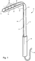
- Retractor 10 has a shaft 12 and a blade 14. Shaft 12 and blade 14 are joined together at an angle, are integral, and the angle may be adjustable (that is the angle between the blade and the shaft may be changed by, for example, bending by hand or by the inclusion of a pivoting mechanism (not shown)). In this embodiment, the angle may be 90° (but may be at other angles, e.g., 45- 135°, or 55-115°, or 55-85°). Additionally, shaft 12 may be telescoping (not shown), so that it's length may be changed.
- the material may be opaque (i.e., non-light transmitting or non-transparent).
- the blade and shaft may be made of any material, metal or plastic.
- the material may be chosen so that the retractor may be sterilized by a variety of methods including, but not limited to, autoclaving, ethylene oxide, radiation, cold sterilization (i.e. hydrogen peroxide plasma), immersion sterilization (i.e. Cidex), or a combination thereof.
- the plastics may be: polyolefins (e.g., polypropylene, ultra high molecular weight polyethylene), polyamides, perfluoroelastomers, polycarbonates, polyetheretherketones (PEEKs), polyphenyl sulfones, acetals, and/or thermoplastic elastomers (e.g., EDPM rubber crosslinked with polypropylene).
- polyolefins e.g., polypropylene, ultra high molecular weight polyethylene
- polyamides e.g., perfluoroelastomers
- polycarbonates e.g., polyetheretherketones (PEEKs), polyphenyl sulfones, acetals, and/or thermoplastic elastomers (e.g., EDPM rubber crosslinked with polypropylene).
- PEEKs polyetheretherketones
- polyphenyl sulfones e.g., EDPM rubber crosslinked
- the blade 14 has an upper surface 16 that may be concave, flat, round or convex.
- a plurality (at least two) of LED (light emitting diode) lights 18 may be disposed along the longitudinal axis of the blade 14. In this embodiment, four lights 18 are shown in-line along the axis; however, other configurations of these lights are possible (e.g., multiple rows and/or columns or other geometric configurations).
- the LED lights 18 face up from the upper surface 16. Face up as used herein means that the major axis of the LED light may be at any angle from 1 to 179° (or 45 to 135°) from the plane of the upper surface 16.
- the LED lights 18 may each face up at differing angles.
- the blade 14 may have a single LED light 18 disposed along the longitudinal axis of the blade 14.
- the blade 14 has an upper surface 16 that may be concare, flat, round or convex.
- One or more LED lights 18 may be disposed along the longitudinal or transverse axis of the blade 14.
- a second surface 20 may also be associated with the upper surface 16 and is located on that portion of the upper surface 16 closer to the shaft 12. This second surface 20 is disposed on the upper surface 16 at an angle and is located behind the LED lights 18. The angle may be such that second surface 20 faces away from the upper surface 16.
- the shaft 12 and the blade 14 have a common lower surface 21.
- a channel 22 is cut into the lower surface 21 of the blade 14 and the shaft 12.
- the channel 22 houses electrical connectors 26 (for example, see Figure 3 ) that connect the LED lights 18 with a power source.
- the channel 22 is closed and sealed with a closure member 26.
- the closure member 24 may be flush with the lower surface 21.
- the closure member 26 may be selected from the group including but not limited to an adhesive, a screw, fastener, or snap on mechanism, or a combination thereof.
- the closure member 24 may be sealed in the channel 22 by use of an adhesive.
- the adhesive may be any adhesive, it may be sterilized by a variety of methods including, but not limited to, autoclaving, ethylene oxide, radiation, cold sterilization (i.e.
- Such adhesives may be epoxies or polyurethanes.
- One such adhesive maybe Loctite's HYSOL M-21HP or M-121HP available from Henkel Corporation of Rocky Hill, CT.
- the lower surface of the blade may also have either a smooth surface or a gripping surface.
- the gripping surface may be used to maintain the retractor in place when inserted into the patient.
- the gripping surface e.g., non-skid
- the gripping surface may be, for example, roughened or ribbed.
- the electrical connectors 26 may be in communication with a cord 30 that is used to connect with a remote power source, as will be understood by those of ordinary skill.
- the first embodiment may be battery powered as discussed below with regard to the second embodiment (and all of the variants of the second embodiment, discussed below, may be incorporated with the first embodiment).
- a gripping surface 28 is located at the lower end of the shaft 12.
- the gripping surface 28 may be adapted for gripping by hand or with clamps.
- LED light 18 has a lens 32 mounted on a base 34. At least a portion of the lens 32 of the LED light 18 may be exposed at surface 16. The outer surface of the lens 32 may be flush with upper surface 16 or may protrude above upper surface 16 (as shown in Figures 4 and 5 ). The LED light 18 is sealed within the blade 14 and there is no cover or blade material enclosing the LED light 18.
- the base 34 may be contained within channel 22.
- the electrical connectors 26 may be attached to the base 34.
- the LED light 18 may be sealed in the channel 22 by use of an adhesive, screws, fasteners or a snap-on mechanism.
- the adhesive may be any adhesive, it may be sterilized by a variety of methods including, but not limited to, autoclaving, ethylene oxide, radiation, cold sterilization (i.e. hydrogen peroxide plasma), immersion sterilization (i.e. Cidex), or a combination thereof.
- Such adhesives may be epoxies or polyurethanes.
- One such adhesive maybe Loctite's HYSOL M-21HP or M-121HP available from Henkel Corporation of Rocky Hill, CT.
- the LED light or lights 18 may be mounted on a PCB board with built in circuitry.
- the PCB board may be either rigid or flexible, depending on the curvature requirement of where the LED lights are mounted on the PCB board.
- the PCB board may then be attached to the blade with an adhesive, screws, fasteners, or simply snap in place (see above for sterilization requirements).
- the PCB board may then be used to place LED lights 18 along either longitudinal axis, transverse axis, or a combination thereof as needed in the case of hook type retractor or in the convex, square, rectangle, or round shaped retractors.
- one or more LED lights 18 may be placed along either longitudinal axis, transverse axis, or a combination thereof as needed in the case of hook type retractor or in the convex, square, rectangle, or round shaped retractors without using the PCB board.
- the LED lights 18 may produce at least 90 lumens (or at least 180 lumens of light).
- the LED lights 18 may be autoclaveable.
- the LED lights 18 may be on a dimmer switch.
- the LED light may be a LUXEON Rebel LXML-PWC1-0090 available from Philips Lumileds Lighting Co. of San Jose, CA.
- a camera 23 may be included in the retractor 10 (see Figures 2 and 3 ).
- Camera 23 may be a still camera or a motion camera. This camera may be based upon CCD (charged-coupled device) technology.
- the camera 23 may be placed in the blade 14 on the second surface 20 behind LED lights 18. In this placement, the camera's field of vision is directed generally down the length of blade 14 and angled away from the upper surface 16, so that the camera 23 is looking at the operative field. This angle (as measured from behind surface 20) may be from 5-90°, or 15-80°, or 30-75°. Thus, the LED lights 18 illuminate, while the camera 23 sees the illuminated area.
- the camera 23 may transmit/store images in any fashion, i.e., via cable, or wireless transmission, or retained in a memory device for later retrieval.
- the CCD can be mounted anywhere along the upper surface 16 on the blade 14 either flush with the blade 14 or on a raised surface.
- second embodiment 10' is similar to first embodiment 10; accordingly, the discussion of the first embodiment 10 is included herein.
- This embodiment may be used 'hands-free,' that is the retractor remains in place without additional securement (hand-held or mechanical) by the weight of the retractor when the blade is inserted into an orifice (such as a vagina or an anus).
- Surgical retractor 10' has a shaft 12 and a blade 14.
- Shaft 12 and blade 14 are joined together at an angle, are integral, and the angle may be adjustable (that is the angle between the blade and the shaft may be changed by, for example, bending by hand or by a pivoting mechanism (not shown)).
- a pair of re-enforcing wings 36 may be located at the intersection of the shaft 12 and the blade 14. In this embodiment, the angle may be 45-135°, or 55-115°, or 55-85° (but may be at other angles, e.g., 90°).
- shaft 12 may be telescoping (not shown), so that it's length may be changed.
- the blade and shaft may be made of any material, metal or plastic.
- This material may be opaque (i.e., non-light transmitting or non-transparent).
- the material may be chosen so that the retractor can be sterilized by a variety of methods including, but not limited to, autoclaving, ethylene oxide, radiation, cold sterilization (i.e. hydrogen peroxide plasma), immersion sterilization (i.e. Cidex), or a combination thereof.
- the plastics may be: polyolefins (e.g., polypropylene, ultra high molecular weight polyethylene), polyamides, perfluoroelastomers, polycarbonates, polyetheretherketones (PEEKs), polyphenyl sulfones, acetals, and/or thermoplastic elastomers (e.g., EDPM rubber crosslinked with polypropylene).
- polyolefins e.g., polypropylene, ultra high molecular weight polyethylene
- polyamides e.g., perfluoroelastomers
- polycarbonates e.g., polycarbonates, polyetheretherketones (PEEKs), polyphenyl sulfones, acetals, and/or thermoplastic elastomers (e.g., EDPM rubber crosslinked with polypropylene).
- PEEKs polyetheretherketones
- polyphenyl sulfones e.g., ED
- the blade 14 has an upper surface 16 that may be concave (or flat or convex).
- a plurality (at least two) of LED (light emitting diode) lights 18 may be disposed along the longitudinal axis of the blade 14. In this embodiment, four lights 18 are shown in-line along the axis; however, other configurations of these lights are possible (e.g., multiple rows and/or columns or other geometric configurations).
- the LED lights 18 face up from the upper surface 16. Face up as used herein means that the major axis of the LED light may be at any angle from 1 to 179° (or 45 to 135°) from the plane of the upper surface 16.
- the LED lights 18 may each face up at differing angles.
- the blade 14 may have a single LED light 18 disposed along the longitudinal axis of the blade 14.
- the blade 14 has an upper surface 16 that may be concare, flat, round or convex.
- One or more LED lights 18 may be disposed along the longitudinal or transverse axis of the blade 14.
- a second surface 20 may also be associated with the upper surface 16 and is located on that portion of the upper surface 16 closer to the shaft 12. This second surface 20 is disposed on the upper surface 16 at an angle and is located behind the LED lights 18. The angle may be such that second surface 20 faces away from the upper surface 16.
- the shaft 12 and the blade 14 have a common lower surface 21.
- a channel 22 is cut into the lower surface 21 of the blade 14 and the shaft 12.
- the channel 22 houses electrical connectors 26 (for example, see Figure 3 ) that connect the LED lights 18 with a power source.
- the channel 22 is closed and sealed with a closure member 26.
- the closure member 26 may be flush with the lower surface 21.
- the closure member 26 may be sealed in the channel 22 by use of an adhesive, screws, fasteners, or snap-on mechanism.
- the adhesive may be any adhesive, it may be sterilized by a variety of methods including, but not limited to, autoclaving, ethylene oxide, radiation, cold sterilization (i.e. hydrogen peroxide plasma), immersion sterilization (i.e. Cidex), or a combination thereof.
- Such adhesives may be epoxies or polyurethanes.
- One such adhesive maybe Loctite's HYSOL M-21HP or M-121 HP available from Henkel Corporation of Rocky Hill, CT
- the lower surface of the blade may also have either a smooth surface or a gripping surface.
- the gripping surface may be used to maintain the retractor in place when inserted into the patient.
- the gripping surface e.g., non-skid
- the gripping surface may be, for example, roughened or ribbed.
- the electrical connectors 26 are in communication with a power source 38 removeably mounted on shaft 12.
- Power source 38 may contain batteries 42 and may be removeably mounted onto shaft 12 via a clamp 40. Additionally, this power source provides a weight, so that the retractor 10' may be used hands-free, as discussed above. Furthermore, this power source 38 is removable from shaft 12. Thus, retractor 10' may be autoclaved without the power source 38. Power source 38 may be autoclaved without the batteries 42. In this situation, a sterile sleeve (not shown) may be used to insert batteries 42 into the sterile power source 38.
- a camera (not shown), as discussed above, may be included in the retractor 10'.
- This camera may be a still camera or a motion camera.
- This camera may be based upon CCD (charged-coupled device) technology.
- the camera may be placed in the blade 14 on the second surface 20 behind LED lights 18.
- the camera's field of vision is directed generally down the length of blade 14 and angled away from the upper surface 16, so that the camera 23 is looking at the operative field.
- This angle (as measured from behind surface 20) may be from 5-90°, or 15-80°, or 30-75°.
- the LED lights 18 illuminate, while the camera 23 sees the illuminated area.
- the camera 23 may transmit/store images in any fashion, i.e., via cable, or wireless transmission, or retained in a memory device for later retrieval.
- the CCD can be mounted anywhere along the upper surface 16 on the blade 14 either flush with the blade 14 or on a raised surface.
- Additional variants of the second embodiment may include: the battery source permanently fixed to the retractor; the battery source and retractor being a single, integral unit; a remote power source (as described above) with a removable weight; a remote power source (as described above) with a non-removable weight.
- a third embodiment of the surgical retractor 10" is shown. All of the features of the first embodiment 10 and the second embodiment 10' may be included in the third embodiment 10".
- the third embodiment 10" may be generally referred to as the speculum embodiment.
- Retractor 10" includes retractor 10 and a second arm 43 moveably affixed to retractor 10.
- Retractor 10 may be the same as previously described retractors 10 and/or 10'; accordingly, further detail discussion may be found above.
- the second arm 43 includes a second shaft 46 joined to second blade 44. Construction of these mating shafts should be such that visualization by the medical professional is not unduly obstructed. In this regard, reference is made to a standard 'duck bill' speculum, incorporated herein by reference.
- Second arm 43 may be moveable along shaft 12 of retractor 10, so that blades 14 and 44 may be spaced apart. Further, blades 14 and 44 may be hinged (not shown) on shafts 12 and 46, respectively; so that the distal tips of blades 14 and 44 may be spread apart further than the hinged portions of the blades 14 and 44.
- Blade 44 is shown as having a concave surface with LED lights, but other configurations are possible (e.g., no lights and no concave surface).
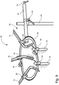
- a surgical retractor kit 48 is shown. All of the features of the first embodiment 10, the second embodiment 10', and the third embodiment 10" may be included in the surgical retractor kit 48.
- the surgical retractor kit 48 may be generally referred to as a self retaining retractor system.
- the surgical retractor kit 48 generally includes a plurality (at least two) retractors 10 (previously discussed retractor 10' may used instead), and a holder set 49.
- Holder set 49 may include a stand 50, arm 52, clamps 54 for fixing and securing the stand 50 and arm 52 in place, mounting ring 56 for placement of the retractors 10, ring clamp 58, and couplers 60 for fixing the retractors in place on mounting ring 56.
- a fifth embodiment of the surgical retractor is shown. All of the features of the previous embodiments may be included in the fifth embodiment.
- This embodiment illustrates a surgical retractor 10''' which has a shaft 12 and a blade 14. Shaft 12 and blade 14 are joined together at an angle, are integral, and the angle may be adjustable (that is the angle between the blade and the shaft may be changed by, for example, bending by hand or by a pivoting mechanism (not shown)). Additionally, a pair of re-enforcing wings 36 may be located at the intersection of the shaft 12 and the blade 14. In this embodiment, the angle may be 45-135°, or 55-115°, or 55-85° (but may be at other angles, e.g., 90°).
- shaft 12 may be telescoping (not shown), so that it's length may be changed.
- the blade and shaft may be made of any material, metal or plastic. This material may be opaque (i.e., non-light transmitting or non-transparent). The material may be chosen so that the retractor can be sterilized by a variety of methods including, but not limited to, autoclaving, ethylene oxide, radiation, cold sterilization (i.e. hydrogen peroxide plasma), immersion sterilization (i.e. Cidex), or a combination thereof.
- the plastics may be: polyolefins (e.g., polypropylene, ultra high molecular weight polyethylene), polyamides, perfluoroelastomers, polycarbonates, polyetheretherketones (PEEKs), polyphenyl sulfones, acetals, and/or thermoplastic elastomers (e.g., EDPM rubber crosslinked with polypropylene).
- polyolefins e.g., polypropylene, ultra high molecular weight polyethylene
- polyamides e.g., perfluoroelastomers
- polycarbonates e.g., polycarbonates, polyetheretherketones (PEEKs), polyphenyl sulfones, acetals, and/or thermoplastic elastomers (e.g., EDPM rubber crosslinked with polypropylene).
- PEEKs polyetheretherketones
- polyphenyl sulfones e.g., ED
- the blade 14 has an upper surface 16 that may be concave (or flat or convex).
- a plurality (at least two) of LED (light emitting diode) lights 18 may be disposed along the longitudinal axis of the blade 14. In this embodiment, four lights 18 are shown in-line along the axis; however, other configurations of these lights are possible (e.g., multiple rows and/or columns or other geometric configurations).
- the LED lights 18 face up from the upper surface 16. Face up as used herein means that the major axis of the LED light may be at any angle from 1 to 179° (or 45 to 135°) from the plane of the upper surface 16.
- the LED lights 18 may each face up at differing angles.
- the blade 14 may have a single LED light 18 disposed along the longitudinal axis of the blade 14.
- the blade 14 has an upper surface 16 that may be concare, flat, round or convex.
- One or more LED lights 18 may be disposed along the longitudinal or transverse axis of the blade 14.
- a second surface 20 may also be associated with the upper surface 16 and is located on that portion of the upper surface 16 closer to the shaft 12. This second surface 20 is disposed on the upper surface 16 at an angle and is located behind the LED lights 18. The angle may be such that second surface 20 faces away from the upper surface 16.
- the shaft 12 and the blade 14 have a common lower surface 21.
- a channel 22 is cut into the lower surface 21 of the blade 14 and the shaft 12.
- the channel 22 houses electrical connectors 26 (for example, see Figure 3 ) that connect the LED lights 18 with a power source.
- the channel 22 is closed and sealed with a closure member 26.
- the closure member 24 may be flush with the lower surface 21.
- the closure member 26 may be sealed in the channel 22 by use of an adhesive, screws, fasteners, or snap-on mechanism.
- the adhesive may be any adhesive, it may be sterilized by a variety of methods including, but not limited to, autoclaving, ethylene oxide, radiation, cold sterilization (i.e. hydrogen peroxide plasma), immersion sterilization (i.e. Cidex), or a combination thereof.
- Such adhesives may be epoxies or polyurethanes.
- One such adhesive maybe Locite's HYSOL M-21HP or M-121 HP available from Henkel Corporation of Rocky Hill, CT.
- the blade 14 also includes a ridge 50 which may be used when attaching to a power source 38.
- the lower surface of the blade may also have either a smooth surface or a gripping surface.
- the gripping surface may be used to maintain the retractor in place when inserted into the patient.
- the gripping surface e.g., non-skid
- the gripping surface may be, for example, roughened or ribbed.
- the electrical connectors 26 are in communication with a power source 38 removeably mounted on shaft 12.
- Power source 38 may contain batteries 42 and may be removeably mounted onto shaft 12 via a clamp 40. Additionally, this power source provides a weight, so that the retractor 10''' may be used hands-free, as discussed above. Furthermore, this power source 38 is removable from shaft 12. Thus, retractor 10''' may be autoclaved without the power source 38. Power source 38 may be autoclaved without the batteries 42. In this situation, a sterile sleeve (not shown) may be used to insert batteries 42 into the sterile power source 38.
- a camera (not shown), as discussed above, may be included in the retractor 10'".
- This camera may be a still camera or a motion camera.
- This camera may be based upon CCD (charged-coupled device) technology.
- the camera may be placed in the blade 14 on the second surface 20 behind LED lights 18.
- the camera's field of vision is directed generally down the length of blade 14 and angled away from the upper surface 16, so that the camera 23 is looking at the operative field.
- This angle (as measured from behind surface 20) may be from 5-90°, or 15-80°, or 30-75°.
- the LED lights 18 illuminate, while the camera 23 sees the illuminated area.
- the camera 23 may transmit/store images in any fashion, i.e., via cable, or wireless transmission, or retained in a memory device for later retrieval.
- the CCD can be mounted anywhere along the upper surface 16 on the blade 14 either flush with the blade 14 or on a raised surface.
- Additional variants of the fifth embodiment may include: the battery source permanently fixed to the retractor; the battery source and retractor being a single, integral unit; a remote power source (as described above) with a removable weight; a remote power source (as described above) with a non-removable weight.
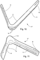
- FIG. 12 and 13 a sixth embodiment of the surgical retractor is shown. All of the features of the previous embodiments may be included in the sixth embodiment.
- This embodiment illustrates a surgical retractor 10"" which has a shaft 12 and a blade 14 with an extension on the end of the blade 14. This extension may be described as a hook 60 as illustrated in Figures 12 and 13 .
- the shaft 12 and blade 14 are joined together at an angle, are integral, and the angle may be adjustable (that is the angle between the blade and the shaft may be changed by, for example, bending by hand or by a pivoting mechanism (not shown)).
- a pair of re-enforcing wings 36 may be located at the intersection of the shaft 12 and the blade 14.
- the angle may be 45-135°, or 55-115°, or 55-85° (but may be at other angles, e.g., 90°).
- shaft 12 may be telescoping (not shown), so that it's length may be changed.
- the blade 14 and hook 60 are joined together at an angle, are integral, and the angle may be adjustable (that is the angle between the blade and the shaft may be changed by, for example, bending by hand or by a pivoting mechanism (not shown)).
- the angle may be 45-135°, or 55-115°, or 55-85° (but may be at other angles, e.g., 90°).
- the blade, shaft and hook may be made of any material, metal or plastic.
- This material may be opaque (i.e., non-light transmitting or non-transparent).
- the material may be chosen so that the retractor can be sterilized by a variety of methods including, but not limited to, autoclaving, ethylene oxide, radiation, cold sterilization (i.e. hydrogen peroxide plasma), immersion sterilization (i.e. Cidex), or a combination thereof.
- the plastics may be: polyolefins (e.g., polypropylene, ultra high molecular weight polyethylene), polyamides, perfluoroelastomers, polycarbonates, polyetheretherketones (PEEKs), polyphenyl sulfones, acetals, and/or thermoplastic elastomers (e.g., EDPM rubber crosslinked with polypropylene).
- polyolefins e.g., polypropylene, ultra high molecular weight polyethylene
- polyamides e.g., perfluoroelastomers
- polycarbonates e.g., polycarbonates, polyetheretherketones (PEEKs), polyphenyl sulfones, acetals, and/or thermoplastic elastomers (e.g., EDPM rubber crosslinked with polypropylene).
- PEEKs polyetheretherketones
- polyphenyl sulfones e.g., ED
- the blade 14 has an upper surface 16 that may be concave (or flat or convex).
- a plurality (at least two) of LED (light emitting diode) lights 18 may be disposed along the longitudinal axis of the blade 14. In this embodiment, four lights 18 are shown in-line along the axis; however, other configurations of these lights are possible (e.g., multiple rows and/or columns or other geometric configurations).
- the LED lights 18 face up from the upper surface 16. Face up as used herein means that the major axis of the LED light may be at any angle from 1 to 179° (or 45 to 135°) from the plane of the upper surface 16.
- the LED lights 18 may each face up at differing angles.
- the blade 14 may have a single LED light 18 disposed along the longitudinal axis of the blade 14.
- the blade 14 has an upper surface 16 that may be concare, flat, round or convex.
- One or more LED lights 18 may be disposed along the longitudinal or transverse axis of the blade 14.
- the hook 60 may be disposed along the longitudinal axis of the blade 14.
- two lights 18 are shown in-line along the longitudinal axis; however, other configurations of these lights are possible (e.g., transverse, multiple rows and/or columns or other geometric configurations).
- the LED lights face up from the surface of the hook. Face up as used herein means that the major axis of the LED light may be at any angle from 1 to 179° (or 45 to 135°) from the plane of the upper surface 16.
- the LED lights 18 may each face up at differing angles. Further, details on the placement of the LED lights 18 may be found in the discussion of Figures 2-5 above.
- the LED lights 18 located on the hook 60 may face in a different direction that the lights located on the upper surface 16 of the blade 14.
- a second surface 20 may also be associated with the upper surface 16 and is located on that portion of the upper surface 16 closer to the shaft 12. This second surface 20 is disposed on the upper surface 16 at an angle and is located behind the LED lights 18. The angle may be such that second surface 20 faces away from the upper surface 16.
- the hook 60, the shaft 12 and the blade 14 have a common lower surface 21.
- a channel 22 is cut into the lower surface 21 of the hook 60, the blade 14 and the shaft 12.
- the channel 22 houses electrical connectors 26 (for example, see Figure 3 ) that connect the LED lights 18 with a power source.
- the channel 22 is closed and sealed with a closure member 26.
- the closure member 24 may be flush with the lower surface 21.
- the closure member 26 may be sealed in the channel 22 by use of an adhesive, screws, fasteners, or snap-on mechanism.
- the adhesive may be any adhesive, it may be sterilized by a variety of methods including, but not limited to, autoclaving, ethylene oxide, radiation, cold sterilization (i.e. hydrogen peroxide plasma), immersion sterilization (i.e.
- Such adhesives may be epoxies or polyurethanes.
- One such adhesive maybe Locite's HYSOL M-21HP or M-121HP available from Henkel Corporation of Rocky Hill, CT.
- the blade 14 also includes a ridge 50 which may be used when attaching to a power source 38.
- the lower surface of the blade may also have either a smooth surface or a gripping surface.
- the gripping surface may be used to maintain the retractor in place when inserted into the patient.
- the gripping surface e.g., non-skid
- the gripping surface may be, for example, roughened or ribbed.
- the electrical connectors 26 are in communication with a power source 38 removeably mounted on shaft 12.
- Power source 38 may contain batteries 42 and may be removeably mounted onto shaft 12 via a clamp 40. Additionally, this power source provides a weight, so that the retractor 10"" may be used hands-free, as discussed previously. Furthermore, this.power source 38 is removable from shaft 12.
- retractor 10"" may be autoclaved without the power source 38.
- Power source 38 may be autoclaved without the batteries 42.
- a sterile sleeve (not shown) may be used to insert batteries 42 into the sterile power source 38.
- a camera (not shown), as discussed above, may be included in the retractor 10"".
- This camera may be a still camera or a motion camera.
- This camera may be based upon CCD (charged-coupled device) technology.
- the camera may be placed in the blade 14 on the second surface 20 behind LED lights 18.
- the camera's field of vision is directed generally down the length of blade 14 and angled away from the upper surface 16, so that the camera 23 is looking at the operative field.
- This angle (as measured from behind surface 20) may be from 5-90°, or 15-80°, or 30-75°.
- the LED lights 18 illuminate, while the camera 23 sees the illuminated area.
- the camera 23 may transmit/store images in any fashion, i.e., via cable, or wireless transmission, or retained in a memory device for later retrieval.
- the CCD can be mounted anywhere along the upper surface 16 on the blade 14 either flush with the blade 14 or on a raised surface.
- Additional variants of the sixth embodiment may include: the battery source permanently fixed to the retractor; the battery source and retractor being a single, integral unit; a remote power source (as described above) with a removable weight; a remote power source (as described above) with a non-removable weight.
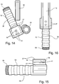
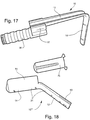
- FIG. 14-17 a seventh embodiment of the surgical retractor is shown. All of the features of the previous embodiments may be included in the seventh embodiment.
- Figures 14-17 illustrate a power source 38 which includes a handle 52 and a pair of extension arms 37 which emanate up from the main body of the power source.
- Each extension arm 37 provides housing for a slot 41 shown in Figures 14 & 15 and each slot 41 has an open end 56 near the handle 52 of the power source and a barrier 58 at the opposite end of the slot 41.
- Each slot 41 works in conjunction with one of the ridges 50 located on the shaft 12 of a surgical retractor.
- the shaft 12 is slideably engaged with the power source 38 by aligning the ridges 50 of the shaft with the open end 56 of each slot 41 and then guiding the ridges 50 within each slot 41 by sliding the shaft 12 away from the handle 52 portion of the power source 38.
- the barriers 58 located at the end of each slot 41 prevent the ridges 50 and the shaft 12 from exiting the slot 41 on the end opposite of the open end 56.
- This design allows the user of the surgical retractor the ability to retract tissue without any concern of the power source 38 disengaging from the shaft 12 as the surgical retractor is pulled while holding the handle 52.
- Figure 14 are a pair of electrical connectors which supply power from the battery 42 to the plurality of LED lights located within the blade 14 or blades of the surgical retractor.
- Figure 17 illustrates a surgical retractor 10 in which the shaft 12 is fully engaged to the power source 38.
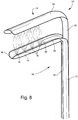
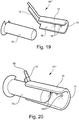
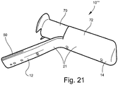
- an eighth embodiment of the surgical retractor is shown. All of the features of the previous embodiments may be included in the eighth embodiment.
- the eighth embodiment 10''''' may be generally referred to a modified speculum embodiment.
- Retractor 10''''' includes retractor 10 and a sleeve 72 which emanates up from the blade 14 of the retractor.
- the sleeve 72 is shown in Figures 18-21 as a semi-circular tube-like shape which hollow and is open at both of its ends such that visualization by the medical professional is not unduly obstructed.
- an insert 70 which may be slideably engaged within the sleeve 72 as shown in Figures 20 and 21 .
- This embodiment may be used 'hands-free,' that is the retractor remains in place without additional securement (hand-held or mechanical) by the weight or girth of the retractor when the blade is inserted into an orifice (such as a vagina or an anus).
- the device would be placed within a patient with the insert 70 engaged within the sleeve 72 of the retractor.
- the insert 70 may then be withdrawn from the sleeve 72 providing an unobstructed line of sight through the hollow portion of the sleeve 72 by the medical professional.
- the blade 14 is shown as having a concave surface with LED lights ( Figures 19 and 20 ), but other configurations are possible (e.g., no lights and no concave surface).
- the surgical retractor 10 there is a zero degree (0°) angle between the shaft 12 and the blade14.
- This may be known in the art as a thyroid/vein retractor or a one end Army-Navy retractor.
- the L.E.D lights may be mounted on the blade 14 and/or on the distal portion of surface 16. This retractor is very useful in ENT, oral, thyroid, and breast surgery.
- the surgical retractor 10 includes a blade 14 with a cross section which is convex, square, rectangular or circular. The LED lights 18 may then be mounted onto two or more separate surfaces of the blade 14 (i.e. at 2-5 surfaces for convex, square and rectangular shape, and all around the circular shape blade 14).
- This embodiment allows for the illumination of greater than 180 degrees in all directions vs LED lights on a single surface with an illumination of less than 180 degrees in a single direction. Furthermore, when the retractor is placed in the center of cavity, it would allow for the full illumination of the entire cavity (serve more than like a lighting mechanism than just a retractor). Additionally, a single or a plurality of CCD may be mounted on one or more surfaces of 13 742 965.0 the surgical retractor 10 to permit visualization anywhere the illumination of the LED lights reaches.
Claims (13)
- Chirurgischer Retraktor (10), umfassend:
einen Schaft (12) mit einem integralen Haken (14), wobei der Schaft und der Haken in einem Winkel miteinander verbunden sind, und der Haken eine Oberseite (16) aufweist;
eine Vielzahl von Leuchten (18) in dem Haken (14) eingebettet sind und auf der Oberseite (16) freiliegen, und wobei der Haken (14), der die Leuchten (18) umgibt,
opak wird;
eine Stromquelle (38), die einen Handgriff enthält (52);
ein Paar elektrische Anschlüsse (26), welche die Vielzahl von Leuchten mit der Stromquelle verbinden, wobei die Stromquelle für die Leuchten in Kommunikation mit den elektrischen Anschlüssen steht und entweder auf dem Schaft oder vom Schaft entfernt getragen wird;
der chirurgische Retraktor ist dadurch gekennzeichnet, dass:die Vielzahl von Leuchten LED-Leuchten sind;der Retraktor ferner ein Paar Rippen (50) umfasst, die sich auf dem Schaft befinden und sich an einem zum Haken entgegengesetzten Ende befinden;die Stromquelle ein Paar Schlitze (41) aufweist, die operativ mit den Rippen assoziiert sind, wobei jeder Schlitz ein offenes Ende (56) nahe dem Handgriff der Stromquelle und eine Sperre (58) am entgegengesetzten Ende des Schlitzes aufweist;wobei der Schaft gleitbar mit den Schlitzen an der Stromquelle in Eingriff gebracht wird, indem jede Rippe des Schafts auf das offene Ende von jedem Schlitz der Stromquelle ausgerichtet wird und die Stromquelle in eine Richtung entgegengesetzt zum Haken geschoben wird, bis das proximale Ende von jeder Rippe in jedem Schlitz liegt und die Sperre von jedem Schlitz erfasst, um lösbar den Schaft an der Stromquelle zu befestigen, und wobei jede Sperre ihre jeweilige Rippe und den Schaft daran hindert, den Schlitz zu verlassen;wobei Haken und Schaft eine Unterseite (21) mit einem integralen Kanal (22) darin und ein den Kanal bedeckendes Verschlusselement (24) aufweisen;wobei der Kanal elektrische Anschlüsse für die Leuchten aufnimmt; undwobei die Stromquelle ferner ein Paar Verlängerungsarme (37) enthält, die sich vom Hauptkörper der Stromquelle aus nach oben erstrecken und für Einhausung der Schlitze sorgen. - Chirurgischer Retraktor nach Anspruch 1, wobei jede der LED-Leuchten eine Linse und eine LED umfasst, wobei die Linse auf der Oberseite freiliegt.
- Chirurgischer Retraktor nach Anspruch 1, wobei jede der LED-Leuchten mit der Oberseite bündig ist oder über die Oberseite hinausragt.
- Chirurgischer Retraktor nach Anspruch 1, wobei die Vielzahl von LED-Leuchten mindestens 90 Lumen abstrahlt.
- Chirurgischer Retraktor nach Anspruch 1, ferner umfassend eine Grifffläche am Schaft.
- Chirurgischer Retraktor nach Anspruch 1, wobei der Winkel zwischen dem Schaft und dem Haken verstellbar ist.
- Chirurgischer Retraktor nach Anspruch 1, wobei der Schaft zusammenschiebbar ist.
- Chirurgischer Retraktor nach Anspruch 1, ferner umfassend einen zweiten Haken, der dem ersten erwähnten Haken gegenüberliegt und auf den vorher erwähnten Haken zu und von ihm weg bewegt werden kann.
- Chirurgischer Retraktor nach Anspruch 1, wobei die Oberfläche konkav ist.
- Chirurgischer Retraktor nach Anspruch 1, ferner umfassend eine Kamera, die am Haken montiert ist.
- Chirurgischer Retraktor nach Anspruch 10, wobei die Kamera auf einer zweiten Seite montiert ist, die an die Oberseite angrenzt.
- Chirurgische Retraktorausrüstung, umfassend einen Montagering, mindestens einen chirurgischen Retraktor nach Anspruch 1 und einen Koppler, um den Retraktor lösbar am Ring zu montieren.
- Chirurgischer Retraktor nach Anspruch 1, ferner umfassend ein Paar Verstärkungsflügel, die sich an der Schnittstelle von Schaft und Haken befinden;
eine Hülse, die sich von dem Haken aus nach oben erstreckt, wobei die Hülse eine halbkreisförmige, röhrenartige Form aufweist, die hohl und an ihren beiden Enden offen ist, sodass die Visualisierung durch die medizinische Fachkraft nicht ungebührlich gehindert wird; und
einen Einsatz, der entfernbar und gleitfähig in die Hülse eingesetzt wird.
Applications Claiming Priority (2)
| Application Number | Priority Date | Filing Date | Title |
|---|---|---|---|
| US13/362,029 US20130197313A1 (en) | 2012-01-31 | 2012-01-31 | Surgical retractor with light |
| PCT/US2013/024098 WO2013116489A1 (en) | 2012-01-31 | 2013-01-31 | Surgical retractor with light |
Publications (3)
| Publication Number | Publication Date |
|---|---|
| EP2809240A1 EP2809240A1 (de) | 2014-12-10 |
| EP2809240A4 EP2809240A4 (de) | 2016-03-16 |
| EP2809240B1 true EP2809240B1 (de) | 2019-09-11 |
Family
ID=48870807
Family Applications (1)
| Application Number | Title | Priority Date | Filing Date |
|---|---|---|---|
| EP13742965.0A Active EP2809240B1 (de) | 2012-01-31 | 2013-01-31 | Chirurgischer retraktor mit licht |
Country Status (3)
| Country | Link |
|---|---|
| US (2) | US20130197313A1 (de) |
| EP (1) | EP2809240B1 (de) |
| WO (1) | WO2013116489A1 (de) |
Families Citing this family (58)
| Publication number | Priority date | Publication date | Assignee | Title |
|---|---|---|---|---|
| EP1865825A4 (de) * | 2005-04-01 | 2009-06-03 | Welch Allyn Inc | Vaginalspekulum |
| US9386915B2 (en) * | 2010-07-30 | 2016-07-12 | Nilesh R. Vasan | Disposable, self-contained laryngoscope and method of using same |
| US9289114B2 (en) * | 2010-07-30 | 2016-03-22 | Nilesh R. Vasan | Disposable, self-contained laryngoscope and method of using same |
| US9913577B2 (en) | 2010-09-28 | 2018-03-13 | Obp Medical Corporation | Speculum |
| US10292784B2 (en) * | 2010-12-10 | 2019-05-21 | Illumix Surgical Canada Inc. | Illuminating surgical device |
| US9622779B2 (en) | 2011-10-27 | 2017-04-18 | DePuy Synthes Products, Inc. | Method and devices for a sub-splenius / supra-levator scapulae surgical access technique |
| US9642606B2 (en) * | 2012-06-27 | 2017-05-09 | Camplex, Inc. | Surgical visualization system |
| US8882662B2 (en) * | 2012-06-27 | 2014-11-11 | Camplex, Inc. | Interface for viewing video from cameras on a surgical visualization system |
| WO2014072976A1 (en) * | 2012-11-08 | 2014-05-15 | Emodi Omri | Intracavity illumination device |
| US9072501B2 (en) * | 2013-03-15 | 2015-07-07 | Regents Of The University Of Minnesota | Micro-orifice surgical access system |
| RU2705046C2 (ru) | 2013-04-01 | 2019-11-01 | Винод В. ПАТХИ | Осветительное устройство |
| USD938095S1 (en) | 2013-04-01 | 2021-12-07 | Pathy Medical, Llc | Lighting device |
| US20140323811A1 (en) * | 2013-04-30 | 2014-10-30 | Invuity, Inc. | Methods and apparatus for retracting tissue |
| WO2014189969A1 (en) | 2013-05-21 | 2014-11-27 | Camplex, Inc. | Surgical visualization systems |
| WO2015042460A1 (en) | 2013-09-20 | 2015-03-26 | Camplex, Inc. | Surgical visualization systems and displays |
| US10881286B2 (en) | 2013-09-20 | 2021-01-05 | Camplex, Inc. | Medical apparatus for use with a surgical tubular retractor |
| US9801748B2 (en) * | 2013-11-08 | 2017-10-31 | Covidien Lp | Devices and methods for facilitating sleeve gastrectomy procedures |
| US9655758B2 (en) | 2013-11-11 | 2017-05-23 | Covidien Lp | Devices and methods facilitating sleeve gastrectomy procedures |
| JP6730765B2 (ja) * | 2014-01-28 | 2020-07-29 | インブイティ・インコーポレイテッド | ドロップイン外科手術用照明器 |
| WO2015164881A1 (en) * | 2014-04-25 | 2015-10-29 | Mindskid Labs, Llc | Illuminating speculum |
| EP3685734B1 (de) * | 2014-05-22 | 2022-03-09 | Invuity, Inc. | Medizinische vorrichtung mit umhülltem wellenleiter |
| US10405844B2 (en) * | 2014-07-16 | 2019-09-10 | Shaw P. Wan | Surgical retractor with light |
| US10702353B2 (en) | 2014-12-05 | 2020-07-07 | Camplex, Inc. | Surgical visualizations systems and displays |
| US20160310121A1 (en) * | 2015-02-05 | 2016-10-27 | Obp Medical | Illuminated Surgical Retractor |
| US9867602B2 (en) * | 2015-02-05 | 2018-01-16 | Obp Medical Corporation | Illuminated surgical retractor |
| US20160278752A1 (en) * | 2015-02-05 | 2016-09-29 | Obp Medical | Illuminated Surgical Retractor |
| US10420538B2 (en) * | 2015-02-05 | 2019-09-24 | Obp Medical Corporation | Illuminated surgical retractor |
| WO2016154589A1 (en) | 2015-03-25 | 2016-09-29 | Camplex, Inc. | Surgical visualization systems and displays |
| JP2018512965A (ja) * | 2015-04-24 | 2018-05-24 | インブイティ・インコーポレイテッド | 手術室機器に適合する手術用器具 |
| US10881387B2 (en) * | 2015-06-03 | 2021-01-05 | Obp Medical Corporation | Retractor |
| CN108348229A (zh) * | 2015-06-03 | 2018-07-31 | Obp医学公司 | 牵开器 |
| US10939899B2 (en) | 2015-06-03 | 2021-03-09 | Obp Medical Corporation | End cap assembly for retractor and other medical devices |
| US10092281B2 (en) | 2015-10-06 | 2018-10-09 | Inmotus Medical Llc | Surgical retractor |
| WO2017091704A1 (en) | 2015-11-25 | 2017-06-01 | Camplex, Inc. | Surgical visualization systems and displays |
| TWI618551B (zh) * | 2016-03-28 | 2018-03-21 | 英濟股份有限公司 | 擴張器 |
| WO2017213662A1 (en) * | 2016-06-10 | 2017-12-14 | Obp Medical | Illuminated surgical retractor |
| US10213271B2 (en) * | 2016-07-06 | 2019-02-26 | Illumix Surgical Canada Inc. | Illuminating surgical device and control element |
| US10722621B2 (en) | 2016-07-11 | 2020-07-28 | Obp Medical Corporation | Illuminated suction device |
| US10219800B2 (en) * | 2016-08-09 | 2019-03-05 | Terumo Cardiovascular Systems Corporation | Minimally-invasive surgery tool with automatic lighting |
| IT201600112850A1 (it) * | 2016-11-09 | 2018-05-09 | Francesco Sias | Anoscopio |
| EP3573537B1 (de) | 2017-01-24 | 2024-02-28 | Medtronic Advanced Energy LLC | Modularer beleuchteter chirurgischer retraktor |
| USD846119S1 (en) | 2017-01-24 | 2019-04-16 | Medtronic Advanced Energy Llc | Lighted surgical retractor base |
| WO2018156488A1 (en) | 2017-02-21 | 2018-08-30 | McCulloch Kenneth | Tensor fascia latae (tfl) protector |
| US20180296081A1 (en) * | 2017-04-18 | 2018-10-18 | Thomas L. Cook | Wireless laryngoscope |
| US11253245B2 (en) | 2017-05-03 | 2022-02-22 | University Of Virginia Patent Foundation | Illuminated suction retractor device |
| WO2018208691A1 (en) | 2017-05-08 | 2018-11-15 | Camplex, Inc. | Variable light source |
| US10687793B2 (en) | 2017-07-18 | 2020-06-23 | Obp Medical Corporation | Minimally invasive no touch (MINT) procedure for harvesting the great saphenous vein (GSV) and venous hydrodissector and retractor for use during the MINT procedure |
| US10278572B1 (en) | 2017-10-19 | 2019-05-07 | Obp Medical Corporation | Speculum |
| WO2019152523A1 (en) * | 2018-01-30 | 2019-08-08 | Rebound Therapeutics Corporation | Devices and method for access and visualization for lumbar interbody fusion (lif) |
| US10512519B2 (en) * | 2018-02-20 | 2019-12-24 | Obp Medical Corporation | Illuminated medical devices |
| US10799229B2 (en) * | 2018-02-20 | 2020-10-13 | Obp Medical Corporation | Illuminated medical devices |
| US11406254B2 (en) * | 2018-07-23 | 2022-08-09 | Covidien Lp | Surgical devices and systems for minimally-invasive vessel-harvesting and other surgical procedures |
| USD876625S1 (en) | 2018-08-07 | 2020-02-25 | Adroit Surgical, Llc | Laryngoscope |
| USD911521S1 (en) | 2019-02-19 | 2021-02-23 | Obp Medical Corporation | Handle for medical devices including surgical retractors |
| USD904607S1 (en) | 2019-05-07 | 2020-12-08 | Obp Medical Corporation | Nasal retractor |
| USD921197S1 (en) * | 2019-09-30 | 2021-06-01 | The Regents Of The University Of Colorado, A Body Corporate | Fin blade |
| US10959609B1 (en) | 2020-01-31 | 2021-03-30 | Obp Medical Corporation | Illuminated suction device |
| US10966702B1 (en) | 2020-02-25 | 2021-04-06 | Obp Medical Corporation | Illuminated dual-blade retractor |
Family Cites Families (70)
| Publication number | Priority date | Publication date | Assignee | Title |
|---|---|---|---|---|
| US2896611A (en) * | 1957-08-08 | 1959-07-28 | Welch Allyn Inc | Orificial instrument construction |
| US3977908A (en) * | 1972-10-17 | 1976-08-31 | Shin-Kobe Electric Machinery Co., Ltd. | Indicator in use with a lead storage battery for indicating the overdischarge of the same and the lowered level of the electrolyte therein |
| US4116232A (en) * | 1977-03-07 | 1978-09-26 | Philipp Rabban | Surgical retractor |
| US4226228A (en) * | 1978-11-02 | 1980-10-07 | Shin Hee J | Multiple joint retractor with light |
| US4300541A (en) * | 1979-02-09 | 1981-11-17 | Kermit Burgin | Speculum lens structure |
| US4344419A (en) * | 1979-12-20 | 1982-08-17 | Kermit Burgin | Acrylooptic tongue depressor and handle therefor |
| US4320745A (en) * | 1980-01-14 | 1982-03-23 | Somsak Bhitiyakul | Fiber optics laryngoscope |
| US4337763A (en) * | 1980-04-21 | 1982-07-06 | The United States Of America As Represented By The Department Of Health, Education And Welfare | Illuminated surgical instrument |
| US4562832A (en) | 1984-01-21 | 1986-01-07 | Wilder Joseph R | Medical instrument and light pipe illumination assembly |
| US4834067A (en) * | 1986-05-30 | 1989-05-30 | Block Irving R | Instrument for internal hemorrhoidectomy |
| US4807599A (en) * | 1987-05-08 | 1989-02-28 | Med-Struments, Inc. | Illuminating tongue depressor |
| US5318009A (en) * | 1993-03-03 | 1994-06-07 | Scientific Medical Programs, Inc. | Illuminated tongue depressor |
| US5520611A (en) * | 1993-12-16 | 1996-05-28 | Rao; Shekar | Illuminated retractor |
| US5967973A (en) * | 1996-04-26 | 1999-10-19 | United States Surgical | Surgical retractor and method of surgery |
| US5865731A (en) * | 1997-01-25 | 1999-02-02 | Lenox-Maclaren | Surgical retractor having variable position retractor blades |
| US5971920A (en) * | 1997-06-18 | 1999-10-26 | Nagel; Gunther Peter | Surgical retractor |
| US7306559B2 (en) * | 1997-07-02 | 2007-12-11 | Lumitex, Inc. | Illuminated surgical retractor |
| US7352339B2 (en) * | 1997-08-26 | 2008-04-01 | Philips Solid-State Lighting Solutions | Diffuse illumination systems and methods |
| US6543447B2 (en) * | 1997-12-01 | 2003-04-08 | Saturn Biomedical Systems Inc | Intubation instrument |
| US6228025B1 (en) * | 1998-05-01 | 2001-05-08 | Genzyme Corporation | Illuminated saphenous vein retractor |
| US20050279355A1 (en) * | 1999-05-04 | 2005-12-22 | Loubser Paul G | Superglottic and peri-laryngeal apparatus having video components for structural visualization and for placement of supraglottic, intraglottic, tracheal and esophageal conduits |
| US6569089B1 (en) * | 1999-12-03 | 2003-05-27 | Roy Covington | Lighted intubating laryngoscope |
| US6497654B1 (en) * | 2000-02-18 | 2002-12-24 | Genzyme Corporation | Illuminated rectal retractor |
| IT1316922B1 (it) * | 2000-09-01 | 2003-05-13 | Paolo Fontana | Anoscopio operatore. |
| US6554768B1 (en) * | 2000-09-05 | 2003-04-29 | Genzyme Corporation | Illuminated deep pelvic retractor |
| US7338441B2 (en) * | 2001-09-06 | 2008-03-04 | Houser Russell A | Superelastic/shape memory tissue stabilizers and surgical instruments |
| US6817978B2 (en) * | 2002-01-23 | 2004-11-16 | Teleflex-Ct Devices Incorporated | Illuminated retractor for use in connection with harvesting a blood vessel from the arm |
| US7766825B2 (en) * | 2002-10-02 | 2010-08-03 | Synthes Usa, Llc | Retractor with interchangeable retractor blades |
| US7371213B2 (en) * | 2003-01-31 | 2008-05-13 | Zimmer Technology, Inc. | Lit retractor |
| US6991604B2 (en) * | 2003-09-04 | 2006-01-31 | Scope Co, Inc. | Dual blade laryngoscope with esophageal obturator |
| EP1706041B1 (de) * | 2003-12-18 | 2015-11-18 | DePuy Spine, Inc. | Chirurgische wundhakensysteme, beleuchtete kanülen und anwendungsverfahren |
| DE102004028428A1 (de) * | 2004-06-03 | 2006-01-26 | Karl Storz Gmbh & Co. Kg | Laryngoskop |
| US7150714B2 (en) * | 2004-06-14 | 2006-12-19 | Ebi, L.P. | Minimally invasive surgical spinal exposure system |
| US8480566B2 (en) * | 2004-09-24 | 2013-07-09 | Vivid Medical, Inc. | Solid state illumination for endoscopy |
| US20060224045A1 (en) * | 2005-03-31 | 2006-10-05 | Depuy Spine, Inc. | Integrated access device and light source for surgical procedures |
| EP1865825A4 (de) * | 2005-04-01 | 2009-06-03 | Welch Allyn Inc | Vaginalspekulum |
| JP2008535551A (ja) * | 2005-04-01 | 2008-09-04 | サターン バイオメディカル システムズ インコーポレイテッド | ビデオ開創器 |
| US8388523B2 (en) * | 2005-04-01 | 2013-03-05 | Welch Allyn, Inc. | Medical diagnostic instrument having portable illuminator |
| US7871375B2 (en) * | 2005-04-05 | 2011-01-18 | Medical Vision Industries, Inc. | LED lighting apparatus and method of using same for illumination of a body cavity |
| WO2007085909A2 (en) * | 2005-09-08 | 2007-08-02 | Synthes (Usa) | Spine retractor and distractor device |
| US20070060795A1 (en) | 2005-09-14 | 2007-03-15 | Spotlight Surgical, Inc. | Lighted surgical retractors with LED illumination light engines |
| US8409088B2 (en) * | 2006-01-18 | 2013-04-02 | Invuity, Inc. | Retractor illumination system |
| US20070208228A1 (en) * | 2006-03-01 | 2007-09-06 | Nicholas Pavento | Surgical retractors and methods of minimally invasive surgery |
| US7384392B2 (en) | 2006-05-22 | 2008-06-10 | Ardeshir Bayat | Disposable expandable cordless lighted retractor |
| US8012089B2 (en) | 2006-05-22 | 2011-09-06 | Ardeshir Bayat | Disposable expandable cordless lighted retractor |
| US7935053B2 (en) * | 2006-06-06 | 2011-05-03 | Globus Medical, Inc | Surgical Retractor System |
| US7686492B2 (en) * | 2006-06-13 | 2010-03-30 | Invuity, Inc. | Film illumination system |
| US20080045801A1 (en) * | 2006-08-15 | 2008-02-21 | M.S. Vision Ltd. | Intubation laryngoscope with detachable blades |
| WO2008031281A1 (fr) * | 2006-09-13 | 2008-03-20 | Helio Optoelectronics Corporation | Ampoule del séparée thermoélectrique enfichable combinée avec un refroidisseur |
| US7587289B1 (en) * | 2007-02-13 | 2009-09-08 | American Megatrends, Inc. | Data cable powered sensor fixture |
| IL181851A0 (en) * | 2007-03-11 | 2007-07-04 | Truphatek Int Ltd | Laryngoscope handle and accessories therefor |
| US9386914B2 (en) * | 2007-04-04 | 2016-07-12 | Karl Storz Endovision, Inc. | Video endoscopic device with detachable control circuit |
| US8029440B2 (en) * | 2007-04-04 | 2011-10-04 | Karl Storz Endovision, Inc. | Video blade laryngoscope |
| US20080269564A1 (en) * | 2007-04-17 | 2008-10-30 | Coopersurgical, Incorporated | Surgical retractor system and method |
| GB0708761D0 (en) * | 2007-05-04 | 2007-06-13 | Evexar Medical Ltd | Improvements in and relating to medical instruments |
| US8088066B2 (en) * | 2007-10-24 | 2012-01-03 | Invuity, Inc. | Blade insert illuminator |
| GB0800835D0 (en) * | 2008-01-17 | 2008-02-27 | Cardioprec Ltd | Retractor |
| CA2717776C (en) * | 2008-03-07 | 2018-05-22 | Milwaukee Electric Tool Corporation | Visual inspection device |
| WO2009117358A2 (en) * | 2008-03-18 | 2009-09-24 | The Trustees Of The University Of Pennsylvania | Trauma retractor |
| US8317693B2 (en) * | 2008-08-13 | 2012-11-27 | Invuity, Inc. | Cyclo olefin polymer and copolymer medical devices |
| US9282878B2 (en) * | 2008-08-13 | 2016-03-15 | Invuity, Inc. | Cyclo olefin polymer and copolymer medical devices |
| US8864654B2 (en) * | 2010-04-20 | 2014-10-21 | Jeffrey B. Kleiner | Method and apparatus for performing retro peritoneal dissection |
| US20100298644A1 (en) * | 2009-05-19 | 2010-11-25 | Bruce Kleene | Co-axial oral intubation device and system |
| TW201043186A (en) * | 2009-06-02 | 2010-12-16 | hui-yu Zhang | Tongue spatula device |
| US8696556B2 (en) * | 2009-07-28 | 2014-04-15 | Endoscopic Technologies, Inc. | Tissue retractors with fluid evacuation/infusion and/or light emission capability |
| US20110040355A1 (en) * | 2009-08-12 | 2011-02-17 | Stacy Francis | Phototherapy mask |
| US20110270042A1 (en) * | 2010-04-29 | 2011-11-03 | Pier Cristoforo Giulianotti | Adjustable surgical support and retractor system |
| US20120059226A1 (en) * | 2010-09-01 | 2012-03-08 | Funt David K | Surgical retractors with illumination |
| US8715172B1 (en) * | 2011-07-11 | 2014-05-06 | Magdy S. Girgis | Double bladed laryngoscope having video camera and liquid crystal display for facilitating intubation procedure |
| EP4279202A3 (de) * | 2011-09-23 | 2024-02-28 | Invuity, Inc. | Chirurgisches instrument zur beleuchtung eines operationsfeldes |
-
2012
- 2012-01-31 US US13/362,029 patent/US20130197313A1/en not_active Abandoned
-
2013
- 2013-01-31 US US14/372,484 patent/US9730685B2/en active Active
- 2013-01-31 EP EP13742965.0A patent/EP2809240B1/de active Active
- 2013-01-31 WO PCT/US2013/024098 patent/WO2013116489A1/en active Application Filing
Non-Patent Citations (1)
| Title |
|---|
| None * |
Also Published As
| Publication number | Publication date |
|---|---|
| EP2809240A4 (de) | 2016-03-16 |
| US20150025324A1 (en) | 2015-01-22 |
| US20130197313A1 (en) | 2013-08-01 |
| WO2013116489A1 (en) | 2013-08-08 |
| US9730685B2 (en) | 2017-08-15 |
| EP2809240A1 (de) | 2014-12-10 |
Similar Documents
| Publication | Publication Date | Title |
|---|---|---|
| EP2809240B1 (de) | Chirurgischer retraktor mit licht | |
| US10405844B2 (en) | Surgical retractor with light | |
| US20180132710A1 (en) | Video retractor | |
| ES2900583T3 (es) | Endoscopio híbrido flexible-rígido y fijaciones de instrumento | |
| US11903567B2 (en) | Body cavity illumination system | |
| EP2395903B1 (de) | Beleuchteter zahnärztlicher retraktor | |
| EP2320967B1 (de) | Medizinische instrumente aus cycloolefinpolymer und cycloolefincopolymer | |
| US10869592B2 (en) | Handheld surgical endoscope | |
| US4562832A (en) | Medical instrument and light pipe illumination assembly | |
| US9282878B2 (en) | Cyclo olefin polymer and copolymer medical devices | |
| US20180318034A1 (en) | Devices and kits for assisting in open surgeries | |
| ES2587366T3 (es) | Aparato de iluminación portátil que puede fijarse para instrumentos quirúrgicos | |
| US20080096165A1 (en) | Cheek And Lip Retractor | |
| ES2599994T3 (es) | Instrumento quirúrgico que incluye característica de alimentación de accesorio | |
| WO1998025512A1 (en) | Light and handle device for vaginal speculum | |
| KR20210133304A (ko) | 휴대용 수술 기구용 조명 장치, 수술 기구 및 조명 장치가 포함된 조명 장치 및 키트가 있는 수술 기구용 홀스터 | |
| US6406293B1 (en) | Hand-held dental transilluminating device |
Legal Events
| Date | Code | Title | Description |
|---|---|---|---|
| PUAI | Public reference made under article 153(3) epc to a published international application that has entered the european phase |
Free format text: ORIGINAL CODE: 0009012 |
|
| 17P | Request for examination filed |
Effective date: 20140826 |
|
| AK | Designated contracting states |
Kind code of ref document: A1 Designated state(s): AL AT BE BG CH CY CZ DE DK EE ES FI FR GB GR HR HU IE IS IT LI LT LU LV MC MK MT NL NO PL PT RO RS SE SI SK SM TR |
|
| AX | Request for extension of the european patent |
Extension state: BA ME |
|
| RAP1 | Party data changed (applicant data changed or rights of an application transferred) |
Owner name: HANGZHOU HAWK OPTICAL ELECTRONIC INSTRUMENTS CO., |
|
| RIN1 | Information on inventor provided before grant (corrected) |
Inventor name: HANGZHOU HAWK OPTICAL ELECTRONIC INSTRUMENTS CO., |
|
| DAX | Request for extension of the european patent (deleted) | ||
| RIC1 | Information provided on ipc code assigned before grant |
Ipc: A61B 1/06 20060101ALI20151019BHEP Ipc: A61B 19/00 20060101ALI20151019BHEP Ipc: A61B 17/02 20060101AFI20151019BHEP Ipc: A61B 17/00 20060101ALN20151019BHEP Ipc: A61B 1/00 20060101ALN20151019BHEP Ipc: A61B 1/32 20060101ALI20151019BHEP Ipc: F21V 33/00 20060101ALI20151019BHEP |
|
| RA4 | Supplementary search report drawn up and despatched (corrected) |
Effective date: 20160212 |
|
| RIC1 | Information provided on ipc code assigned before grant |
Ipc: A61B 1/32 20060101ALI20160216BHEP Ipc: A61B 1/00 20060101ALN20160216BHEP Ipc: A61B 90/00 20160101ALI20160216BHEP Ipc: A61B 1/06 20060101ALI20160216BHEP Ipc: F21V 33/00 20060101ALI20160216BHEP Ipc: A61B 17/00 20060101ALN20160216BHEP Ipc: A61B 17/02 20060101AFI20160216BHEP |
|
| R17P | Request for examination filed (corrected) |
Effective date: 20140826 |
|
| STAA | Information on the status of an ep patent application or granted ep patent |
Free format text: STATUS: EXAMINATION IS IN PROGRESS |
|
| 17Q | First examination report despatched |
Effective date: 20170222 |
|
| GRAP | Despatch of communication of intention to grant a patent |
Free format text: ORIGINAL CODE: EPIDOSNIGR1 |
|
| STAA | Information on the status of an ep patent application or granted ep patent |
Free format text: STATUS: GRANT OF PATENT IS INTENDED |
|
| RIC1 | Information provided on ipc code assigned before grant |
Ipc: A61B 90/30 20160101ALI20190305BHEP Ipc: A61B 17/00 20060101ALN20190305BHEP Ipc: A61B 1/32 20060101ALI20190305BHEP Ipc: A61B 1/06 20060101ALI20190305BHEP Ipc: A61B 1/00 20060101ALN20190305BHEP Ipc: A61B 17/02 20060101AFI20190305BHEP Ipc: F21V 33/00 20060101ALI20190305BHEP |
|
| INTG | Intention to grant announced |
Effective date: 20190327 |
|
| RIC1 | Information provided on ipc code assigned before grant |
Ipc: A61B 1/32 20060101ALI20190319BHEP Ipc: F21V 33/00 20060101ALI20190319BHEP Ipc: A61B 17/00 20060101ALN20190319BHEP Ipc: A61B 17/02 20060101AFI20190319BHEP Ipc: A61B 90/30 20160101ALI20190319BHEP Ipc: A61B 1/00 20060101ALN20190319BHEP Ipc: A61B 1/06 20060101ALI20190319BHEP |
|
| GRAS | Grant fee paid |
Free format text: ORIGINAL CODE: EPIDOSNIGR3 |
|
| GRAA | (expected) grant |
Free format text: ORIGINAL CODE: 0009210 |
|
| STAA | Information on the status of an ep patent application or granted ep patent |
Free format text: STATUS: THE PATENT HAS BEEN GRANTED |
|
| RIN1 | Information on inventor provided before grant (corrected) |
Inventor name: WAN, SHAW, P. |
|
| AK | Designated contracting states |
Kind code of ref document: B1 Designated state(s): AL AT BE BG CH CY CZ DE DK EE ES FI FR GB GR HR HU IE IS IT LI LT LU LV MC MK MT NL NO PL PT RO RS SE SI SK SM TR |
|
| REG | Reference to a national code |
Ref country code: GB Ref legal event code: FG4D |
|
| REG | Reference to a national code |
Ref country code: CH Ref legal event code: EP |
|
| REG | Reference to a national code |
Ref country code: AT Ref legal event code: REF Ref document number: 1177466 Country of ref document: AT Kind code of ref document: T Effective date: 20190915 |
|
| REG | Reference to a national code |
Ref country code: DE Ref legal event code: R096 Ref document number: 602013060376 Country of ref document: DE Ref country code: IE Ref legal event code: FG4D |
|
| REG | Reference to a national code |
Ref country code: NL Ref legal event code: MP Effective date: 20190911 |
|
| REG | Reference to a national code |
Ref country code: LT Ref legal event code: MG4D |
|
| PG25 | Lapsed in a contracting state [announced via postgrant information from national office to epo] |
Ref country code: HR Free format text: LAPSE BECAUSE OF FAILURE TO SUBMIT A TRANSLATION OF THE DESCRIPTION OR TO PAY THE FEE WITHIN THE PRESCRIBED TIME-LIMIT Effective date: 20190911 Ref country code: LT Free format text: LAPSE BECAUSE OF FAILURE TO SUBMIT A TRANSLATION OF THE DESCRIPTION OR TO PAY THE FEE WITHIN THE PRESCRIBED TIME-LIMIT Effective date: 20190911 Ref country code: NO Free format text: LAPSE BECAUSE OF FAILURE TO SUBMIT A TRANSLATION OF THE DESCRIPTION OR TO PAY THE FEE WITHIN THE PRESCRIBED TIME-LIMIT Effective date: 20191211 Ref country code: BG Free format text: LAPSE BECAUSE OF FAILURE TO SUBMIT A TRANSLATION OF THE DESCRIPTION OR TO PAY THE FEE WITHIN THE PRESCRIBED TIME-LIMIT Effective date: 20191211 Ref country code: FI Free format text: LAPSE BECAUSE OF FAILURE TO SUBMIT A TRANSLATION OF THE DESCRIPTION OR TO PAY THE FEE WITHIN THE PRESCRIBED TIME-LIMIT Effective date: 20190911 Ref country code: SE Free format text: LAPSE BECAUSE OF FAILURE TO SUBMIT A TRANSLATION OF THE DESCRIPTION OR TO PAY THE FEE WITHIN THE PRESCRIBED TIME-LIMIT Effective date: 20190911 |
|
| PG25 | Lapsed in a contracting state [announced via postgrant information from national office to epo] |
Ref country code: RS Free format text: LAPSE BECAUSE OF FAILURE TO SUBMIT A TRANSLATION OF THE DESCRIPTION OR TO PAY THE FEE WITHIN THE PRESCRIBED TIME-LIMIT Effective date: 20190911 Ref country code: LV Free format text: LAPSE BECAUSE OF FAILURE TO SUBMIT A TRANSLATION OF THE DESCRIPTION OR TO PAY THE FEE WITHIN THE PRESCRIBED TIME-LIMIT Effective date: 20190911 Ref country code: GR Free format text: LAPSE BECAUSE OF FAILURE TO SUBMIT A TRANSLATION OF THE DESCRIPTION OR TO PAY THE FEE WITHIN THE PRESCRIBED TIME-LIMIT Effective date: 20191212 Ref country code: AL Free format text: LAPSE BECAUSE OF FAILURE TO SUBMIT A TRANSLATION OF THE DESCRIPTION OR TO PAY THE FEE WITHIN THE PRESCRIBED TIME-LIMIT Effective date: 20190911 Ref country code: ES Free format text: LAPSE BECAUSE OF FAILURE TO SUBMIT A TRANSLATION OF THE DESCRIPTION OR TO PAY THE FEE WITHIN THE PRESCRIBED TIME-LIMIT Effective date: 20190911 |
|
| REG | Reference to a national code |
Ref country code: AT Ref legal event code: MK05 Ref document number: 1177466 Country of ref document: AT Kind code of ref document: T Effective date: 20190911 |
|
| PG25 | Lapsed in a contracting state [announced via postgrant information from national office to epo] |
Ref country code: AT Free format text: LAPSE BECAUSE OF FAILURE TO SUBMIT A TRANSLATION OF THE DESCRIPTION OR TO PAY THE FEE WITHIN THE PRESCRIBED TIME-LIMIT Effective date: 20190911 Ref country code: NL Free format text: LAPSE BECAUSE OF FAILURE TO SUBMIT A TRANSLATION OF THE DESCRIPTION OR TO PAY THE FEE WITHIN THE PRESCRIBED TIME-LIMIT Effective date: 20190911 Ref country code: EE Free format text: LAPSE BECAUSE OF FAILURE TO SUBMIT A TRANSLATION OF THE DESCRIPTION OR TO PAY THE FEE WITHIN THE PRESCRIBED TIME-LIMIT Effective date: 20190911 Ref country code: RO Free format text: LAPSE BECAUSE OF FAILURE TO SUBMIT A TRANSLATION OF THE DESCRIPTION OR TO PAY THE FEE WITHIN THE PRESCRIBED TIME-LIMIT Effective date: 20190911 Ref country code: IT Free format text: LAPSE BECAUSE OF FAILURE TO SUBMIT A TRANSLATION OF THE DESCRIPTION OR TO PAY THE FEE WITHIN THE PRESCRIBED TIME-LIMIT Effective date: 20190911 Ref country code: PT Free format text: LAPSE BECAUSE OF FAILURE TO SUBMIT A TRANSLATION OF THE DESCRIPTION OR TO PAY THE FEE WITHIN THE PRESCRIBED TIME-LIMIT Effective date: 20200113 Ref country code: PL Free format text: LAPSE BECAUSE OF FAILURE TO SUBMIT A TRANSLATION OF THE DESCRIPTION OR TO PAY THE FEE WITHIN THE PRESCRIBED TIME-LIMIT Effective date: 20190911 |
|
| PG25 | Lapsed in a contracting state [announced via postgrant information from national office to epo] |
Ref country code: SK Free format text: LAPSE BECAUSE OF FAILURE TO SUBMIT A TRANSLATION OF THE DESCRIPTION OR TO PAY THE FEE WITHIN THE PRESCRIBED TIME-LIMIT Effective date: 20190911 Ref country code: IS Free format text: LAPSE BECAUSE OF FAILURE TO SUBMIT A TRANSLATION OF THE DESCRIPTION OR TO PAY THE FEE WITHIN THE PRESCRIBED TIME-LIMIT Effective date: 20200224 Ref country code: CZ Free format text: LAPSE BECAUSE OF FAILURE TO SUBMIT A TRANSLATION OF THE DESCRIPTION OR TO PAY THE FEE WITHIN THE PRESCRIBED TIME-LIMIT Effective date: 20190911 Ref country code: SM Free format text: LAPSE BECAUSE OF FAILURE TO SUBMIT A TRANSLATION OF THE DESCRIPTION OR TO PAY THE FEE WITHIN THE PRESCRIBED TIME-LIMIT Effective date: 20190911 |
|
| REG | Reference to a national code |
Ref country code: DE Ref legal event code: R097 Ref document number: 602013060376 Country of ref document: DE |
|
| PLBE | No opposition filed within time limit |
Free format text: ORIGINAL CODE: 0009261 |
|
| STAA | Information on the status of an ep patent application or granted ep patent |
Free format text: STATUS: NO OPPOSITION FILED WITHIN TIME LIMIT |
|
| PG2D | Information on lapse in contracting state deleted |
Ref country code: IS |
|
| PG25 | Lapsed in a contracting state [announced via postgrant information from national office to epo] |
Ref country code: DK Free format text: LAPSE BECAUSE OF FAILURE TO SUBMIT A TRANSLATION OF THE DESCRIPTION OR TO PAY THE FEE WITHIN THE PRESCRIBED TIME-LIMIT Effective date: 20190911 Ref country code: IS Free format text: LAPSE BECAUSE OF FAILURE TO SUBMIT A TRANSLATION OF THE DESCRIPTION OR TO PAY THE FEE WITHIN THE PRESCRIBED TIME-LIMIT Effective date: 20200112 |
|
| 26N | No opposition filed |
Effective date: 20200615 |
|
| PG25 | Lapsed in a contracting state [announced via postgrant information from national office to epo] |
Ref country code: SI Free format text: LAPSE BECAUSE OF FAILURE TO SUBMIT A TRANSLATION OF THE DESCRIPTION OR TO PAY THE FEE WITHIN THE PRESCRIBED TIME-LIMIT Effective date: 20190911 Ref country code: MC Free format text: LAPSE BECAUSE OF FAILURE TO SUBMIT A TRANSLATION OF THE DESCRIPTION OR TO PAY THE FEE WITHIN THE PRESCRIBED TIME-LIMIT Effective date: 20190911 |
|
| REG | Reference to a national code |
Ref country code: CH Ref legal event code: PL |
|
| REG | Reference to a national code |
Ref country code: BE Ref legal event code: MM Effective date: 20200131 |
|
| PG25 | Lapsed in a contracting state [announced via postgrant information from national office to epo] |
Ref country code: LU Free format text: LAPSE BECAUSE OF NON-PAYMENT OF DUE FEES Effective date: 20200131 |
|
| PG25 | Lapsed in a contracting state [announced via postgrant information from national office to epo] |
Ref country code: CH Free format text: LAPSE BECAUSE OF NON-PAYMENT OF DUE FEES Effective date: 20200131 Ref country code: LI Free format text: LAPSE BECAUSE OF NON-PAYMENT OF DUE FEES Effective date: 20200131 Ref country code: BE Free format text: LAPSE BECAUSE OF NON-PAYMENT OF DUE FEES Effective date: 20200131 |
|
| PG25 | Lapsed in a contracting state [announced via postgrant information from national office to epo] |
Ref country code: IE Free format text: LAPSE BECAUSE OF NON-PAYMENT OF DUE FEES Effective date: 20200131 |
|
| PG25 | Lapsed in a contracting state [announced via postgrant information from national office to epo] |
Ref country code: TR Free format text: LAPSE BECAUSE OF FAILURE TO SUBMIT A TRANSLATION OF THE DESCRIPTION OR TO PAY THE FEE WITHIN THE PRESCRIBED TIME-LIMIT Effective date: 20190911 Ref country code: MT Free format text: LAPSE BECAUSE OF FAILURE TO SUBMIT A TRANSLATION OF THE DESCRIPTION OR TO PAY THE FEE WITHIN THE PRESCRIBED TIME-LIMIT Effective date: 20190911 Ref country code: CY Free format text: LAPSE BECAUSE OF FAILURE TO SUBMIT A TRANSLATION OF THE DESCRIPTION OR TO PAY THE FEE WITHIN THE PRESCRIBED TIME-LIMIT Effective date: 20190911 |
|
| PG25 | Lapsed in a contracting state [announced via postgrant information from national office to epo] |
Ref country code: MK Free format text: LAPSE BECAUSE OF FAILURE TO SUBMIT A TRANSLATION OF THE DESCRIPTION OR TO PAY THE FEE WITHIN THE PRESCRIBED TIME-LIMIT Effective date: 20190911 |
|
| PGFP | Annual fee paid to national office [announced via postgrant information from national office to epo] |
Ref country code: FR Payment date: 20230124 Year of fee payment: 11 |
|
| PGFP | Annual fee paid to national office [announced via postgrant information from national office to epo] |
Ref country code: GB Payment date: 20230124 Year of fee payment: 11 Ref country code: DE Payment date: 20230118 Year of fee payment: 11 |