EP3573537B1 - Modularer beleuchteter chirurgischer retraktor - Google Patents
Modularer beleuchteter chirurgischer retraktor Download PDFInfo
- Publication number
- EP3573537B1 EP3573537B1 EP18701638.1A EP18701638A EP3573537B1 EP 3573537 B1 EP3573537 B1 EP 3573537B1 EP 18701638 A EP18701638 A EP 18701638A EP 3573537 B1 EP3573537 B1 EP 3573537B1
- Authority
- EP
- European Patent Office
- Prior art keywords
- blade
- surgical retractor
- neck
- modular surgical
- handle
- Prior art date
- Legal status (The legal status is an assumption and is not a legal conclusion. Google has not performed a legal analysis and makes no representation as to the accuracy of the status listed.)
- Active
Links
- 238000000034 method Methods 0.000 description 9
- 230000000712 assembly Effects 0.000 description 8
- 238000000429 assembly Methods 0.000 description 8
- 238000010276 construction Methods 0.000 description 8
- 239000000835 fiber Substances 0.000 description 3
- 238000005286 illumination Methods 0.000 description 3
- 239000000463 material Substances 0.000 description 3
- 238000001356 surgical procedure Methods 0.000 description 3
- 230000000295 complement effect Effects 0.000 description 2
- 238000010586 diagram Methods 0.000 description 2
- 230000013011 mating Effects 0.000 description 2
- 230000000717 retained effect Effects 0.000 description 2
- 206010013975 Dyspnoeas Diseases 0.000 description 1
- 101100112673 Rattus norvegicus Ccnd2 gene Proteins 0.000 description 1
- 239000000853 adhesive Substances 0.000 description 1
- 230000001070 adhesive effect Effects 0.000 description 1
- 230000009286 beneficial effect Effects 0.000 description 1
- 239000011248 coating agent Substances 0.000 description 1
- 238000000576 coating method Methods 0.000 description 1
- 238000005516 engineering process Methods 0.000 description 1
- 230000001788 irregular Effects 0.000 description 1
- 208000014259 low grade vulvar intraepithelial neoplasia Diseases 0.000 description 1
- 210000000056 organ Anatomy 0.000 description 1
- 239000007787 solid Substances 0.000 description 1
- 238000002627 tracheal intubation Methods 0.000 description 1
Images


Classifications
-
- A—HUMAN NECESSITIES
- A61—MEDICAL OR VETERINARY SCIENCE; HYGIENE
- A61B—DIAGNOSIS; SURGERY; IDENTIFICATION
- A61B17/00—Surgical instruments, devices or methods, e.g. tourniquets
- A61B17/02—Surgical instruments, devices or methods, e.g. tourniquets for holding wounds open; Tractors
-
- A—HUMAN NECESSITIES
- A61—MEDICAL OR VETERINARY SCIENCE; HYGIENE
- A61B—DIAGNOSIS; SURGERY; IDENTIFICATION
- A61B1/00—Instruments for performing medical examinations of the interior of cavities or tubes of the body by visual or photographical inspection, e.g. endoscopes; Illuminating arrangements therefor
- A61B1/06—Instruments for performing medical examinations of the interior of cavities or tubes of the body by visual or photographical inspection, e.g. endoscopes; Illuminating arrangements therefor with illuminating arrangements
-
- A—HUMAN NECESSITIES
- A61—MEDICAL OR VETERINARY SCIENCE; HYGIENE
- A61B—DIAGNOSIS; SURGERY; IDENTIFICATION
- A61B1/00—Instruments for performing medical examinations of the interior of cavities or tubes of the body by visual or photographical inspection, e.g. endoscopes; Illuminating arrangements therefor
- A61B1/32—Devices for opening or enlarging the visual field, e.g. of a tube of the body
-
- A—HUMAN NECESSITIES
- A61—MEDICAL OR VETERINARY SCIENCE; HYGIENE
- A61B—DIAGNOSIS; SURGERY; IDENTIFICATION
- A61B90/00—Instruments, implements or accessories specially adapted for surgery or diagnosis and not covered by any of the groups A61B1/00 - A61B50/00, e.g. for luxation treatment or for protecting wound edges
- A61B90/30—Devices for illuminating a surgical field, the devices having an interrelation with other surgical devices or with a surgical procedure
-
- A—HUMAN NECESSITIES
- A61—MEDICAL OR VETERINARY SCIENCE; HYGIENE
- A61B—DIAGNOSIS; SURGERY; IDENTIFICATION
- A61B90/00—Instruments, implements or accessories specially adapted for surgery or diagnosis and not covered by any of the groups A61B1/00 - A61B50/00, e.g. for luxation treatment or for protecting wound edges
- A61B90/36—Image-producing devices or illumination devices not otherwise provided for
-
- A—HUMAN NECESSITIES
- A61—MEDICAL OR VETERINARY SCIENCE; HYGIENE
- A61B—DIAGNOSIS; SURGERY; IDENTIFICATION
- A61B17/00—Surgical instruments, devices or methods, e.g. tourniquets
- A61B2017/0046—Surgical instruments, devices or methods, e.g. tourniquets with a releasable handle; with handle and operating part separable
- A61B2017/00473—Distal part, e.g. tip or head
-
- A—HUMAN NECESSITIES
- A61—MEDICAL OR VETERINARY SCIENCE; HYGIENE
- A61B—DIAGNOSIS; SURGERY; IDENTIFICATION
- A61B17/00—Surgical instruments, devices or methods, e.g. tourniquets
- A61B2017/00681—Aspects not otherwise provided for
- A61B2017/00734—Aspects not otherwise provided for battery operated
Definitions
- the present disclosure relates to surgical tools. More particularly, it relates to hand held retractor instruments for use in surgical procedures, for example in retracting tissue, organs, etc.
- Retractors generally include a handle and a blade.
- the blade extends from the handle at an approximately 90 degree angle, and is typically sized and shaped for a particular procedure (e.g., a longer and/or wider blade may be appropriate for retracting tissue deep inside a body of the patient, whereas a shorter and/or narrower blade may be more appropriate for retracting skin at an incision).
- a surgical team normally must have a large number of differently-configured retractors available.
- a separate light source such as a head-mounted light or other light source located in the surgical suite.
- lighted retractors have been suggested with which a fiber optic light guide is loaded to the retractor body itself. With this approach, light from the fiber optic light guide can be emitted more directly over and along a face of the blade, thus more directly illuminating the surgical site. While beneficial, fiber optic light guides are relatively expensive and may negatively affect a surgeon's ability to freely move his or her hands. Further, light may not be provided at a location desired by the user, and power requirement may be excessive.
- Document us 2010/069722 discloses an intubation laryngoscope having reusable and disposable blades adapted for right- and left-handed operation, an illumination system mounted on a laryngoscope handle, and improved fastening appliance for detachable connection of the blades to the laryngoscope handle.
- the inventors of the present disclosure recognized that a need exists for surgical retractors that overcome one or more of the above-mentioned problems.
- the handle includes a base and a neck.
- the base defines opposing, first and second ends.
- the neck projects from the first end of the base to a tail region.
- the blade includes a head section and a blade member.
- the head section includes a first side wall, an opposing second side wall, and a floor.
- the side walls and the floor combine to define a slot sized to receive the neck.
- the blade member projects from the head section.
- the handle and the blade are configured to provide an attached state in which the blade is removably attached to the handle. In the attached state, an attachment face of each of the side walls is in contact with the first end of the base, and the floor is in contact with the tail region.
- the blade can be robustly attached to the handle in a manner providing an enhanced interface sufficient to maintain a structural integrity of the retractor when the blade member is subjected to expected tissue lifting or retraction forces.
- the neck defines an inside face, an outside face opposite the inside face, and opposing side faces.
- the attached state further includes at least a portion of the inside face in contact with the floor. At least a segment of the inside face is curved in extension from the first end to the tail region.
- the inside face is substantially flat along the tail region, and the floor includes a substantially flat segment.
- the attached state further includes the inside face of the tail region in contact with the substantially flat segment of the floor.
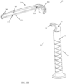
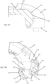
- the surgical retractor 20 includes a handle assembly 22 and at least one blade, such as a first blade 24A. Details on the various components are provided below.
- the handle assembly 22 includes a handle 30 maintaining a light source assembly 32 (referenced generally in FIGS. 1A and 1B ).
- the handle 30 and the blade 24A incorporate complementary mating features that facilitate selective, robust attachment of the blade 24A to the handle 30 in the attached state of FIG. 1A .
- the light source assembly 32 is arranged to emit light along the blade 24A in the attached state.
- the complementary mating features allow the blade 24A to be readily, manually removable from the handle 30 (as in FIG. 1B ). Once removed, another, potentially differently-configured blade can be attached to the handle 30 as described below.
- the handle 30 can assume various forms, and includes or defines a base 40 and a neck 42.
- the base 40 and the neck 42 can be integrally formed as a continuous, homogenous structure in some embodiments.
- the handle 30 is configured to maintain other components of the handle assembly 22.
- the handle assembly 22 can include a power source 50 and a power delivery assembly 52.
- the handle 30 can be formed by first and second handle segments 54, 56 that are separately formed and, upon final assembly, collectively form the base 40 and the neck 42 (best identified in FIGS. 1A and 1B ).
- the base 40 can form or define a cavity 60 (referenced generally) within which the power source 50 and the power delivery assembly 52 are maintained, and the neck 42 can form or define a passage 62 within which the light source assembly 32 is maintained.
- the base 40 is generally configured for grasping or handling by an adult human hand, and can have the elongated, cylindrical-like shape as shown. Other shapes are also acceptable, and an exterior of the base 40 optionally includes texturing 64 (referenced generally) that promotes gripping of the base 40 by a user's hand. For example, a coating, sleeve, skin, etc., can be applied to an exterior of the base 40 (and the neck 42) that provides the texturing 64 or other grip-enhancing feature.
- the elongated shape defines a longitudinal axis A, with the base 40 extending along the longitudinal axis A and terminating at opposing, first and second ends 70, 72.
- the neck 42 projects from the first end 70 as described in greater detail below.
- the second end 72 can have a variety of forms, and in some embodiments has an expanded outer dimension (e.g., diameter) as compared to a remainder of the base 40 serving as a platform for supporting the handle 30 in an upright positioned when placed on a flat surface.
- the first end 70 can have a generally circular shape, with the neck 42 being centrally disposed within a shape of the first end 70.
- a size and shape of the neck 42 are less than that of the first end 70, and the neck 42 is centrally located relative to the first end 70.
- one or more shoulders such as first and second shoulder segments 74, 76, are established along the first end 70.
- the shoulder segments 74, 76 are located at opposite sides of the neck 42 and in some embodiments are substantially flat (i.e., within 5% of a truly flat surface).
- a latch 78 can be formed as an outward projection from the first end 70 and that is aligned with the neck 42.
- a notch 80, 82 can be defined in each of the shoulder segments 74, 76, respectively.
- the base 40 forms a first interior ledge 84 adjacent the notch 80 in the first shoulder segment 74, and a second interior ledge 86 adjacent the notch 82 in the second segment 76.
- the shoulder segments 74, 76, the latch 78, the notches 80, 82, and the interior ledges 84, 86 are configured to interface with corresponding features of the blade 24A ( FIGS. 1A and 1B ) as described below.
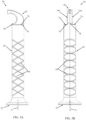
- the neck 42 is shown in greater detail in FIGS. 4A and 4B , and projects from the first end 70 of the base 40 to a tail region 90.
- the tail region 90 terminates at a tail end 92.
- the passage 62 is open to or at the tail end 92.
- a geometry of the neck 42 in extension from the first end 70 spatially off-sets the tail region 90, including the tail end 92, relative to the first end both longitudinally and transversely in some embodiments.
- the longitudinal axis A is identified in FIGS. 4A and 4B , along with an X, Y, Z coordinate system.
- the longitudinal axis A corresponds with the X axis.
- the Y axis is orthogonal to the X axis
- the Z axis is orthogonal to the X and Y axes.
- the neck 42 can incorporate various shapes in establishing the above-described spatial relationship of the tail region 90 and the tail end 92 relative to the first end 70 of the base 40.
- a shape of the neck 42 can be described as including or defining an inside face 100, an outside face 102, and opposing, first and second side faces 104, 106 (the second side face 106 is hidden in FIGS. 4A and 4B , and is generally identified in FIG. 3B ).
- at least a portion, for example a guide portion 110, of the inside face 100 is curved in extension from the base 40.
- a curvature established by the inside face 100 can be or include a concave curve relative to the longitudinal axis A.
- a relatively uniform curvature or radius of curvature can be established along at least a majority of the guide portion 110.
- the inside face 100 can have a complex or non-uniform curvature, can be curvilinear, or can be linear in extension from the base 40 to the tail region 90.
- the inside face 100 is substantially flat (i.e., within 5% of a truly flat surface) along the tail region 90.
- a major plane P1 established by the inside face 100 along the tail region 90 is substantially parallel (i.e., within 5 degrees of a truly parallel relationship) with a major plane P2 of the shoulder segments 74, 76 for reasons made clear below.
- the outside face 102 optionally has a curvature generally mimicking that of the inner face 100 to establish a streamlined shape, with the neck 42 generally tapering in the transverse direction (Y axis) in extension from the base 40.
- the outside face 102 can project away from the inside face 100 along the tail region 90 in extension to the tail end 92; with this optional geometry, the passage 62 can be appropriately sized to receive the light source assembly 32 ( FIG. 2 ).
- the side faces 104, 106 can be substantially identical in some embodiments, and are optionally substantially planar or flat. As best shown in FIG. 4A , the notch 80 in the first shoulder segment 74 can extend into or be partially formed by the first side face 104. Though hidden in the views, the notch 82 in the second shoulder segment 76 can similarly extend into or be partially formed by the second side face 106.
- the passage 62 within the neck 42 is more clearly shown in FIG. 4C .
- the passage 62 is open to the tail end 92 and includes or provides a pocket region 120 sized and shaped for mounting of the light source assembly 32 ( FIG. 2 ).
- a flange 122 can be formed at a side of the pocket region 120 opposite the tail end 92.
- a distance between the flange 122 and the tail end 92 corresponds with a geometry of the light source assembly 32 such that the flange 122 provides a surface against which the light source assembly 32 can be mounted at a known location relative to the tail end 92.
- a channel 124 is defined through the flange 122 such that the passage 62 can be continuously open to the cavity 60 in the base 40.
- wiring (not shown) or other electrical circuitry can be routed from the base 40 to the pocket region 120 (and thus to the light source assembly 32 mounted within the pocket region 120).
- a curvature of the inside and outside faces 100, 102 in extension from the base 40 to the tail region 90, along with the optional non-parallel relationship of the inside and outside faces 100, 102 along the tail region 90 results in a centerline CL1 of the passage 62 along the pocket region 120 being non-perpendicular (and non-parallel) to a major plane P3 of the tail end 92.
- the light source assembly 32 can be configured to accommodate this off-set arrangement while maintaining the streamlined shape of the neck 42.
- the light source assembly 32 includes a light source 130 and an optional lens 132.
- the light source 130 can assume various forms, and in some embodiments includes one (or more) light emitting diodes (LEDs) 134 and corresponding circuitry (e.g., the LED 134 is attached to a circuit board 136).
- LEDs light emitting diodes
- the lens 132 is configured for assembly to the light source 130 and to direct or affect emitted light.
- One embodiment of the lens 132 is shown in greater detail in FIGS. 5A-5D .
- the lens 132 can include or lens body 140, opposing tabs 142, 144, and one or more fingers 146 projecting from a respective one of the tabs 142, 144.
- the lens body 140 can be a solid structure, formed of a material appropriate for allowing passage of light (e.g., a transparent, semi-transparent, or translucent material).
- the lens body 140 defines opposing, leading and trailing sides 150, 152.
- An aperture 154 is defined in the lens body 140 at the trailing side 152, sized and shaped to receive the LED 134 ( FIG. 2 ).
- the leading side 150 provides a structured or ridged surface 156 configured to focus and shape light. In other embodiments, the leading side 150 is substantially flat and does not include ridges or other light affecting structures. In some embodiments, the lens body 140 is shaped such that a major plane P4 established by the leading side 150 is non-perpendicular (and non-parallel) with a centerline CL2 of the lens body 140. This optional off-set relationship corresponds with a geometry of the neck 42 ( FIG. 4C ) as described above.
- the tabs 142, 144 project from opposite sides of the lens body 140, and are sized and shaped for mounting within and to the neck passage 62 ( FIG. 4C ).
- the fingers 146 project from the tabs 142, 144 in a direction of and beyond the trailing side 152 of the lens body 140, and also serve to provide robust mounting within the neck passage 62.
- the lens 132 can incorporate other mounting features that may or may not include one or more of the tabs 142, 144 and/or the fingers 146.
- the power source 50 can assume various forms, and in some embodiments includes one or more batteries 160.
- the batteries 160 are selected in accordance with power requirements of the light source 130, and in some embodiments, the power source 50 consists of two, AA batteries 150 (e.g., 1.5 volt). Other power source formats are also acceptable.
- the surgical retractors of the present disclosure need not incorporate a light source carried by the handle 30, and thus need not include the power source 50.
- the power delivery assembly 52 is formatted for delivering power from the power source 50 to the light source 130 in an appropriate manner.
- the power delivery assembly 52 includes a driver 170 and an actuator or switch 172.
- the driver 170 is electrically connected (e.g., via wiring 174) to the switch 172 that in turn is electrically connected to the power source 50.
- the driver 170 is further electrically connected to the light source 130 via wiring 176.
- the actuator 172 can be a mechanical switch (e.g., spring-loaded) that when actuated, allows delivery of power from the power source 50 to the driver 170; subsequent actuation of the actuator 172 discontinues the delivery of power to the driver 170.
- a cap 178 is optionally assembled to the actuator 172 to promote user interface with the actuator 172.
- the driver 170 is a constant current LED driver of a type known in the art.
- the driver 170 can be a constant current LED driver available from Microchip Technology Inc. under the trade designation MCP1643.
- the corresponding circuit e.g., wiring and other electrical components
- the corresponding circuit can assume various forms appropriate for supplying power to the light source 130.
- a circuit used to drive an LED as the light source 130 is provided in FIG. 6 .
- the circuit diagram of FIG. 6 reflects that the driver 170 is connected to a positive side of the battery through a pushbutton switch (labeled as "VIN-1"), and directly to a negative side of the power source (labeled as "GND-1"). Further, the driver 170 is directly connected to the LED cathode at "K-1" and the LED anode at "A-1".
- Other circuit designs are also acceptable.
- the power delivery assembly 52 can optionally further include a circuit interrupter strip 180.
- the interrupter strip 180 is slidably disposed between a terminal of the power source 50 and the power delivery circuitry. Prior to powering of the light source 130, the interrupter strip 180 is removed by the user, thereby completing the power delivery circuit. In other embodiments, the interrupter strip 180 can be omitted.
- the power source 50 is carried by and retained within the base 40.
- the driver 170 along with other components of the power delivery assembly 52 (referenced generally) such as wiring (not shown) are also carried by and retained within the base 40.
- the cap 178, and thus the actuator 172 is accessible at an opening in the second end 72.
- the interrupter strip 180 where provided, is located between a terminal of the power source 50 and a contact 182 (best seen in FIG. 2 ) of the power delivery assembly 52, and extends outwardly through a slot in the base 40.
- the interrupter strip 180 is thus accessible by a user; by pulling the interrupter strip 180 from the base 40, the power delivery circuit is complete, providing power from the power source 50 to the actuator 172, and thus the driver 170.
- the light source 132 is assembled to the lens 130, including the LED 134 located within the lens body 140.
- the lens 130 and the light source 132 are mounted within the pocket region 120 in a fixed manner.
- the light source assembly 52 can be press-fit into the pocket region 120 and/or one more attachment materials (e.g., adhesive) can be employed.
- at least the light source 132, and optionally the lens 130 is permanently attached to the handle 30 and is not removable therefrom by a user under normal conditions of use.
- the leading side 150 of the lens body 140 is aligned with, optionally flush to, the tail end 92.
- the lens body 140 is arranged such that the major plane P4 of the leading side 150 is substantially parallel with (i.e., within 5 degrees of a truly parallel relationship) the major plane P3 of the tail end 92; in related embodiments, the major planes P3, P4 are substantially co-planar (i.e., within 5 degrees of a truly co-planar relationship).
- the substantially co-planar major planes P3, P4 can be substantially perpendicular (i.e., within 5 degrees of a truly perpendicular relationship) to one or both of the major plane P1 of the inside face 100 along the tail region 90 and the major plane P2 of the shoulder segments 74, 76 (it being understood that the shoulder segments 74, 76 are not readily evident in the cross-sectional view of FIG. 7B but are shown, for example, in FIGS. 4A and 4B ).
- the first blade 24A includes or defines a head section 200 and a blade member 202.
- the head section 200 is configured for removable attachment to the handle 30.
- the blade member 202 extends from the head section 200 and can assume various forms appropriate for certain surgical retraction procedures.
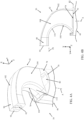
- the head section 200 is shown in greater detail in FIGS. 8A-8C , and generally includes or defines a head body 210 and one or more clip assemblies, such as first and second clip assemblies 212, 214.
- the head body 210 can be an integral or homogenous structure extending between or defining a first or blade face 216 and a second or attachment face 218.
- the head body 210 further defines a slot 220 extending between and open to the blade and attachment faces 216, 218.
- the slot 220 can be viewed as being defined bounded by a floor 230, a first side wall 232 and an opposing, second side wall 234. As best shown in FIG.
- the floor 230 defines a shape or curvature that corresponds with the shape and curvature of the inside face 100 ( FIG. 4B ) of the neck 42 ( FIG. 4B ) as described above.
- the floor 230 can include or define a convex curved segment 236 that has substantially identical (i.e., within 5% of a truly identical relationship) geometry as the guide portion 110 ( FIG. 4B ).
- the floor 230 includes or defines a contact segment 238 at or adjacent the blade face 216 that is substantially flat (i.e., within 5% of a truly flat surface) for reasons made clear below.
- the side walls 232, 234 can be viewed as continuously extending between the blade and attachment faces 216, 218, each define an exterior shape or geometry mimicking that of the outside face 102 ( FIG. 4B ) of the neck 42 ( FIG. 4B ) as described above.
- Other constructions or shapes are also envisioned, and the side walls 232, 234 need not be identical.
- the attachment face 218 can be substantially flat or planar (i.e., within 5 degrees of a truly flat surface) in some embodiments as generally reflected by the figures.
- the perspective view of FIG. 9B illustrates that the attachment face 218 can be viewed as being formed or defined by first and second face segments 240, 242.
- the first face segment 240 corresponds with the first side wall 232 and the second face segment 242 corresponds with the second side wall 234.
- the floor 230 is partially visible in the view of FIG. 9B .
- the face segments 240, 242 collectively define the attachment face 218 and are substantially flat and co-planar.
- the head body 210 can further include or define a collar 244 collectively defined by or interconnecting the floor 230 and the side walls 232, 234 apart from the attachment face 218.
- a recess 246 can be defined through a partial thickness of the collar 244 for reasons made clear below.
- the first clip assembly 212 is generally associated or aligned with the first side wall 232, and the second clip assembly 214 is generally associated with the second side wall 234.
- the clip assemblies 212, 214 can be identical in some embodiments, such that the following description of the first clip assembly 212 applies equally to the second clip assembly 214.
- the first clip assembly 212 includes a clip 270 and an optional guide member 272.
- the clip 270 and the guide member 272 each project from the attachment face 218 (e.g., the first face segment 240) in a laterally spaced apart arrangement.
- the clip 270 can be provided as part of or connected to a tab 274.
- the tab 274 is pivotably connected to a remainder of the head body 210 (e.g., relative to a remainder of the first side wall 232), for example at a living hinge 276, and is biased to the spatial arrangement shown.
- the clip 270 can be articulated inwardly (i.e., in a direction toward the guide member 272) in response to an inward or pressing force applied to the tab 274, when the clip 270 is subjected to an inward force, etc.
- the tab 274 self-reverts back to the arrangement of FIG. 9B , locating the clip 270 relative to the guide member 272 as shown.
- the guide member 272, where provided is more rigidly secured to the first side wall 232.
- the clip assemblies 212, 214 are configured to effectuate releasable engagement with the handle 30 ( FIG. 2 ).
- Other attachment formats are also acceptable that may or may not include one or both of the clip assemblies 212, 214.
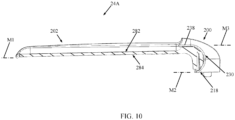
- the blade member 202 extends from the head section 202 to a leading edge 280.
- the blade member 202 can have a various shapes and sizes.
- a shape of the blade member 202 can be viewed as defining opposing, interior and exterior surfaces 282, 284.
- the surfaces 282, 284 can have the uniform, curved shape as shown, or a number of other shapes that can be regular or irregular between the head section 202 and the leading edge 280. As further shown in FIG.
- the interior surface 282 is longitudinally off-set from the contact segment 238 of the floor 230 (e.g., the interior surface 282 is "below" the contact segment 238 relative to the orientation of FIG. 10 ). Geometry of the interior surface 282 relative to the contact segment 238 corresponds with geometry of the handle assembly 22 ( FIG. 2 ) so as to promote desired light dispersement as described below. Further, a major plane M1 established by the exterior surface 284 (again, relative to the cross-sectional view of FIG. 10 ) can be substantially parallel (i.e., within 5 degrees of a truly parallel relationship) with one or both of a major plane M2 established by the attachment face 218 and a major plane M3 established by the contact segment 238 is some embodiments.
- the blade 24A can be manually attached to the handle 30 in a simple and straightforward manner.
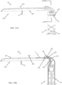
- the blade 24A is initially spatially arranged relative to the handle assembly 22 such that the slot 220 (referenced generally in FIG. 11B , more clearly shown, for example, in FIG. 1B ) is generally aligned with neck 42.
- the blade 24A is generally spatially rotated relative to the handle 30 as shown such that clip assemblies 212, 214 "clear" the first end 70 of the base 40 as the head section 200 is subsequently directed toward the neck 42 in a direction indicated by an arrow in FIGS. 11A and 11B .
- FIGS. 12A and 12B Directing of the head section 200 onto the neck 42 is shown in FIGS. 12A and 12B .
- the neck 42 is generally located within the slot 220, with the floor 230 contacting the inside face 100 (best seen in FIG. 12B ).
- the clip assemblies 212, 214 are spaced from the first end 70 of the base 40, and are away from the corresponding notch 80, 82 (one of which is partially visible in FIG. 12A ).
- the blade 24A is then rotated relative to the handle 30 (and/or vice-versa), sliding and pivoting along the contacting interface between the floor 230 and the inside face 100 of the neck 42.
- the matching geometry of the floor 230 and the inside face 100 promotes the clip assemblies 212, 214 becoming aligned with the corresponding notch 80, 82.
- the attachment surface 218 of the blade 24A is brought into contact with the shoulder segments 74, 76 (one of which is visible in FIG. 12A ) of the handle 30.
- Contact between the attachment surface 218 and the shoulder segments 74, 76 serves as a stop to further rotation.
- a stop to further rotation is also provided by contact between substantially flat contact segment 238 of the floor 230 and the substantially flat inside face 100 along the tail region 90.
- FIGS. 13A-13C Final attachment between the blade 24A and the handle 30 is reflected by FIGS. 13A-13C .
- the attachment surface 218 contacts or abuts against the shoulder segments 74, 76, optionally with a flush interface.
- the inside face 100 along the tail region 90 contacts or abuts against the contact segment 238 of the floor 230.
- the clips 270 are received within a corresponding one of the notches 80, 82, and engage with a corresponding one of the interior ledges 84, 86.
- the latch 78 nests within the recess 246 (more clearly visible in FIG. 1A ).
- the surgical retractor 20 can be utilized by a practitioner to perform various surgical retraction procedures as desired.
- the base 40 is appropriately sized for convenient handling by a single hand of the user.
- the blade member 202 extends at an approximately 90 degree angle relative to the base 40, and is thus conducive to many expected surgical retraction procedures performed by a user while gasping the base 40.
- the surgical retractor 20 will be employed to lift and/or push tissue.
- a surgical retraction procedure includes locating the exterior surface 284 of the blade member 202 against tissue to be retracted, followed by the user applying a pulling force on to the handle 30 so as to retract the contacted tissue.
- the contacted tissue naturally resists the retraction force, effectively generates a tissue force F against the blade member 202 in response to the user-applied pulling force on the handle 30.
- the force F creates a moment of the matched radius section of the blade 24A and the handle 30 in the same direction (e.g., at the interface between the neck inside face 100 and the floor 230).
- the blade 24A is held in a position normal to the handle 30 by contact between the attachment surface 218 of the blade 24A with the shoulder segments 74, 76 of the handle 30, and by contact between contact segment 238 of the floor 230 of the blade 24A with the inside face 100 of the handle 30 along the tail region 90.
- the tissue force F is thus dispersed through these contact areas and into the handle 30, creating a strong interface that facilitates use of the surgical retractor 20 in performing tissue retraction procedures requiring high tissue lifting forces.
- the light source 130 can be powered on as described above (e.g., via operation of the power delivery assembly 52 ( FIG. 2 )).
- the lens body 140 directs light from the light source 132 along or in general alignment with the interior surface 282 of the blade member 202 (emitted light L is generally drawn in FIG. 13B ).
- the blade 24A can be removed from the handle 30.
- the tabs 274 are pressed inwardly, causing the corresponding clip 270 to disengage from the respective interior ledge 84, 86.
- the blade 24A can then be rotated relative to the handle 30 (and/or vice-versa) in a reverse manner to the attachment steps described above, thereby freeing the blade 24A from the handle 30.
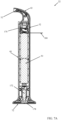
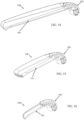
- FIG. 14 Another blade 24B useful with the modular surgical retractors of the present disclosure is shown in FIG. 14 and includes the head section 200 as described above and a blade member 300.
- a size and shape of the blade member 300 differs from that of the blade member 202 ( FIG. 1B ).
- the blade 24B is readily attached to and removed from the handle 30 ( FIG. 1B ) commensurate with the descriptions above.
- FIG. 15 another optional blade 24C in accordance with principles of the present disclosure is shown in FIG. 15 and includes the head section 200 and a blade member 310.
- FIG. 16 illustrates yet another optional blade 24D in accordance with principles of the present disclosure that includes the head section 200 and a blade member 320.
- two or more or all of the blades 24A, 24B, 24C, 24D can be provided to a clinician along with the handle assembly 22 ( FIG. 1B ) as part of a kit.
- the user can select the desired the blade, attach the selected blade to the handle assembly 22, and perform the procedure.
- the modular surgical retractors of the present disclosure provide a marked improvement over previous designs.
- a variety of different blades are readily attached to and removed from an ergonomic handle, with a strong, robust interface being established between the blade and the handle when attached.
- a light source is carried by the handle, located to emit light along an attached blade in a manner conducive to desired illumination of the surgical field.
- modular surgical retractors have been described with reference to preferred embodiments, workers skilled in the art will recognize that changes can be made in form and detail without departing from the scope of the present disclosure.
- the modular surgical retractors have been described as including a light source carried by the handle, in other embodiments the modular surgical retractors of the present disclosure need not include a light source.
Claims (13)
- Modularer chirurgischer Spreizer, umfassend:
einen Griff (30), einschließlich:einer Basis (40), die ein gegenüberliegendes erstes (70) und zweites (72) Ende definiert,eines Halses (42), der von dem ersten Ende zu einer hinteren Endregion (90) vorsteht,
undeiner ersten Klinge (24A), einschließlich:eines Kopfbereichs (200), einschließlich einer ersten Seitenwand (232), einer gegenüberliegenden zweiten Seitenwand (234) und eines Bodens (230), die kombiniert sind, um einen Schlitz (220) zu definieren, der bemessen ist, um den Hals aufzunehmen,eines Klingenelements (202), das aus dem Kopfbereich vorsteht;wobei der Griff und die erste Klinge konfiguriert sind, um einen angebrachten Zustand bereitzustellen, in dem die erste Klinge an dem Griff entfernbar angebracht ist, wobei der angebrachte Zustand eine Anbringungsfläche (216, 218) jeder der Seitenwände in Kontakt mit dem ersten Ende und dem Boden in Kontakt mit der hinteren Endregion einschließt;wobei der Hals eine Innenfläche (100), eine Außenfläche (102) gegenüber der Innenfläche und gegenüberliegende Seitenflächen definiert, und wobei ferner der angebrachte Zustand mindestens einen Abschnitt der Innenfläche in Kontakt mit dem Boden einschließt; und wobei mindestens ein Segment der Innenfläche in Verlängerung von dem ersten Ende zu der hinteren Endregion gekrümmt ist, undwobei die Innenfläche im Wesentlichen flach entlang der hinteren Endregion ist, und ferner wobei der Boden ein im Wesentlichen flaches Segment einschließt, und ferner wobei der angebrachte Zustand die Innenfläche der hinteren Endregion in Kontakt mit dem im Wesentlichen flachen Segment des Bodens einschließt. - Modularer chirurgischer Spreizer nach Anspruch 1, wobei der Spreizer derart konfiguriert ist, dass in dem zusammengebauten Zustand eine Schnittstelle zwischen den Seitenwänden und dem ersten Ende und zwischen dem Boden und der hinteren Endregion einer Kraft widersteht, die auf das Klingenelement ausgeübt wird, das lotrecht zu einer Hauptebene des Klingenelements ist.
- Modularer chirurgischer Spreizer nach Anspruch 1 oder 2, wobei das erste Ende ein erstes und ein zweites Schultersegment (74, 76) an gegenüberliegenden Seiten des Halses definiert, und ferner wobei der angebrachte Zustand die Anbringungsfläche (216) der ersten Seitenwand in Kontakt mit dem ersten Schultersegment und der Anbringungsfläche (218) der zweiten Seitenwand in Kontakt mit dem zweiten Schultersegment einschließt.
- Modularer chirurgischer Spreizer nach Anspruch 3, wobei der Kopfbereich ferner eine erste Klammer (270) einschließt, die von der Anbringungsfläche der ersten Seitenwand vorsteht, und ferner wobei der angebrachte Zustand die erste Klammer einschließt, die innerhalb der ersten Kerbe verschachtelt ist.
- Modularer chirurgischer Spreizer nach Anspruch 4, wobei die Basis eine zweite Kerbe (82) in dem ersten Ende ausbildet, wobei sich die erste und die zweite Kerbe an gegenüberliegenden Seiten des Halses befinden, und ferner wobei der Kopfbereich ferner eine zweite Klammer (270) einschließt, die von der Anbringungsfläche der zweiten Seitenwand vorsteht, und noch ferner wobei der angebrachte Zustand die zweite Klammer einschließt, die innerhalb der zweiten Kerbe verschachtelt ist.
- Modularer chirurgischer Spreizer nach einem der Ansprüche 1 bis 5, wobei die Basis eine längliche Form aufweist, die eine Längsachse definiert, und ferner wobei die hintere Endregion von dem ersten Ende in sowohl einer Längsrichtung parallel zu der Längsachse als auch einer Querrichtung senkrecht zu der Längsachse versetzt ist.
- Modularer chirurgischer Spreizer nach einem der vorstehenden Ansprüche,
wobei der Boden eine Krümmung definiert, die im Wesentlichen identisch mit einer Krümmung der Innenfläche ist. - Modularer chirurgischer Spreizer nach einem der Ansprüche 1 bis 7, ferner umfassend:
eine Lichtquelle (130), die innerhalb des Halses eingerichtet ist, und vorzugsweise wobei die Lichtquelle an dem Hals fixiert ist. - Modularer chirurgischer Spreizer nach Anspruch 8, wobei der angebrachte Zustand das von der Lichtquelle emittierte Licht einschließt, das auf eine Fläche des Klingenelements gerichtet ist.
- Modularer chirurgischer Spreizer nach einem der Ansprüche 8 und 9, ferner umfassend eine Linse (132), die zwischen der Lichtquelle und einem offenen Ende der hinteren Endregion eingerichtet ist.
- Modularer chirurgischer Spreizer nach einem der Ansprüche 8 bis 10, ferner umfassend eine Leistungsquelle (50), die innerhalb der Basis eingerichtet ist, und vorzugsweise wobei die Leistungsquelle mindestens zwei Batterien (160) einschließt.
- Modularer chirurgischer Spreizer nach Anspruch 11, ferner umfassend eine Schaltung, die innerhalb der Basis eingerichtet und konfiguriert ist, um die Leistungsquelle mit der Lichtquelle wahlweise elektrisch zu verbinden.
- Modularer chirurgischer Spreizer nach einem der Ansprüche 1 bis 12, ferner umfassend: eine zweite Klinge einschließlich:eines Kopfbereichs,eines Klingenelements, das aus dem Kopfbereich vorsteht;wobei sich das Klingenelement der zweiten Klinge von dem Klingenelement der ersten Klinge durch mindestens einen Parameter unterscheidet, der aus der Gruppe ausgewählt ist, bestehend aus Größe und Form;und ferner wobei der Kopfbereich der zweiten Klinge und der Kopfbereich der ersten Klinge identisch sind.
Applications Claiming Priority (2)
| Application Number | Priority Date | Filing Date | Title |
|---|---|---|---|
| US201762449650P | 2017-01-24 | 2017-01-24 | |
| PCT/US2018/012515 WO2018140208A1 (en) | 2017-01-24 | 2018-01-05 | Modular lighted surgical retractor |
Publications (2)
| Publication Number | Publication Date |
|---|---|
| EP3573537A1 EP3573537A1 (de) | 2019-12-04 |
| EP3573537B1 true EP3573537B1 (de) | 2024-02-28 |
Family
ID=61028232
Family Applications (1)
| Application Number | Title | Priority Date | Filing Date |
|---|---|---|---|
| EP18701638.1A Active EP3573537B1 (de) | 2017-01-24 | 2018-01-05 | Modularer beleuchteter chirurgischer retraktor |
Country Status (3)
| Country | Link |
|---|---|
| US (2) | US10736618B2 (de) |
| EP (1) | EP3573537B1 (de) |
| WO (1) | WO2018140208A1 (de) |
Families Citing this family (16)
| Publication number | Priority date | Publication date | Assignee | Title |
|---|---|---|---|---|
| US9913577B2 (en) | 2010-09-28 | 2018-03-13 | Obp Medical Corporation | Speculum |
| US10420538B2 (en) | 2015-02-05 | 2019-09-24 | Obp Medical Corporation | Illuminated surgical retractor |
| US9867602B2 (en) | 2015-02-05 | 2018-01-16 | Obp Medical Corporation | Illuminated surgical retractor |
| US10939899B2 (en) | 2015-06-03 | 2021-03-09 | Obp Medical Corporation | End cap assembly for retractor and other medical devices |
| CN108348229A (zh) | 2015-06-03 | 2018-07-31 | Obp医学公司 | 牵开器 |
| US10881387B2 (en) | 2015-06-03 | 2021-01-05 | Obp Medical Corporation | Retractor |
| US10722621B2 (en) | 2016-07-11 | 2020-07-28 | Obp Medical Corporation | Illuminated suction device |
| US10687793B2 (en) | 2017-07-18 | 2020-06-23 | Obp Medical Corporation | Minimally invasive no touch (MINT) procedure for harvesting the great saphenous vein (GSV) and venous hydrodissector and retractor for use during the MINT procedure |
| US10278572B1 (en) | 2017-10-19 | 2019-05-07 | Obp Medical Corporation | Speculum |
| EP3755234A4 (de) | 2018-02-20 | 2021-11-17 | OBP Surgical Corporation | Beleuchtete medizinische vorrichtungen |
| US10799229B2 (en) | 2018-02-20 | 2020-10-13 | Obp Medical Corporation | Illuminated medical devices |
| USD911521S1 (en) | 2019-02-19 | 2021-02-23 | Obp Medical Corporation | Handle for medical devices including surgical retractors |
| USD904607S1 (en) | 2019-05-07 | 2020-12-08 | Obp Medical Corporation | Nasal retractor |
| US10959609B1 (en) | 2020-01-31 | 2021-03-30 | Obp Medical Corporation | Illuminated suction device |
| US10966702B1 (en) | 2020-02-25 | 2021-04-06 | Obp Medical Corporation | Illuminated dual-blade retractor |
| US11583270B2 (en) * | 2020-10-14 | 2023-02-21 | Matrixlabs Medical Co., Ltd | Needle set of laparoscopic surgery and knotting device thereof |
Family Cites Families (82)
| Publication number | Priority date | Publication date | Assignee | Title |
|---|---|---|---|---|
| US4638792A (en) * | 1979-12-20 | 1987-01-27 | Burgin Kermit H | Adjustable speculum with incorporated lighting system |
| US4344419A (en) * | 1979-12-20 | 1982-08-17 | Kermit Burgin | Acrylooptic tongue depressor and handle therefor |
| US4697578A (en) | 1981-07-17 | 1987-10-06 | Burgin Kermit H | Acrylooptic tongue depressor and handle therefor incorporating adjustable viewing optics |
| US5947896A (en) | 1996-04-26 | 1999-09-07 | United States Surgical Corporation | Heart stabilizer apparatus and method for use |
| US6322500B1 (en) | 1996-12-23 | 2001-11-27 | University Of Massachusetts | Minimally invasive surgical apparatus |
| US6196968B1 (en) | 1997-06-02 | 2001-03-06 | General Surgical Innovations, Inc. | Direct vision subcutaneous tissue retractor and method for use |
| US6035742A (en) | 1997-06-16 | 2000-03-14 | Valcor Concept Marketing, Inc. | Handlebar grip assembly |
| US6080105A (en) | 1997-06-26 | 2000-06-27 | Spears; Robert A. | Illuminated dental and surgical retractor and kit including plurality of blades and blades recharging base |
| US7306559B2 (en) | 1997-07-02 | 2007-12-11 | Lumitex, Inc. | Illuminated surgical retractor |
| US5967971A (en) | 1998-04-14 | 1999-10-19 | Bolser; Jeffrey William | Surgical instrument |
| US5928139A (en) | 1998-04-24 | 1999-07-27 | Koros; Tibor B. | Retractor with adjustable length blades and light pipe guides |
| USD425202S (en) | 1999-01-21 | 2000-05-16 | Hu-Friedy Mfg. Co., Inc. | Dental instrument handle |
| US6109918A (en) | 1999-01-21 | 2000-08-29 | Hu-Friedy Mfg. Co., Inc. | Dental instrument having overlapping helical scoring pattern |
| US6331157B2 (en) | 1999-04-15 | 2001-12-18 | Heartport, Inc. | Apparatus and methods for off-pump cardiac surgery |
| US6364832B1 (en) | 1999-12-23 | 2002-04-02 | Tri-State Hospital Supply Corporation | Vaginal lateral walls retractor for use in combination with vaginal specula and method of performing vaginal/cervical examination |
| US6322499B1 (en) | 2000-01-20 | 2001-11-27 | Genzyme Corporation | Pivotal and illuminated saphenous vein retractor |
| US6554768B1 (en) | 2000-09-05 | 2003-04-29 | Genzyme Corporation | Illuminated deep pelvic retractor |
| USD453292S1 (en) | 2000-11-28 | 2002-02-05 | Hiroshi Tsuzuki | Handle grip |
| US6929606B2 (en) | 2001-01-29 | 2005-08-16 | Depuy Spine, Inc. | Retractor and method for spinal pedicle screw placement |
| US6729877B2 (en) | 2001-07-30 | 2004-05-04 | Hu-Friedy Mfg. Co., Inc. | Dental instrument having enlarged handle and glued cone |
| USD461390S1 (en) | 2001-09-04 | 2002-08-13 | Paul M. Livingston | Grip for handle bar |
| US6817978B2 (en) | 2002-01-23 | 2004-11-16 | Teleflex-Ct Devices Incorporated | Illuminated retractor for use in connection with harvesting a blood vessel from the arm |
| US6805666B2 (en) | 2002-05-23 | 2004-10-19 | Donna D. Holland | Pivotal and illuminated saphenous vein retractor with tapered design |
| US7766825B2 (en) | 2002-10-02 | 2010-08-03 | Synthes Usa, Llc | Retractor with interchangeable retractor blades |
| US6893394B2 (en) | 2002-12-19 | 2005-05-17 | Ethicon, Inc. | Illuminated and vacuum assisted retractor |
| WO2004077922A2 (en) | 2003-03-07 | 2004-09-16 | Howmedica Osteonics Corporation | Illuminable retractor |
| US7481766B2 (en) | 2003-08-14 | 2009-01-27 | Synthes (U.S.A.) | Multiple-blade retractor |
| US7905840B2 (en) | 2003-10-17 | 2011-03-15 | Nuvasive, Inc. | Surgical access system and related methods |
| US20050240081A1 (en) | 2004-04-22 | 2005-10-27 | The Cleveland Clinic Foundation | Laryngoscope blade |
| DE102004028428A1 (de) | 2004-06-03 | 2006-01-26 | Karl Storz Gmbh & Co. Kg | Laryngoskop |
| US20060084032A1 (en) | 2004-10-14 | 2006-04-20 | Tipton David W | Rotatable dental handle |
| US8187180B2 (en) | 2005-04-01 | 2012-05-29 | Verathon Medical (Canada) Ulc | Video rectractor |
| US8684577B2 (en) | 2005-05-13 | 2014-04-01 | Invuity, Inc. | Body cavity illumination system |
| US20070060795A1 (en) | 2005-09-14 | 2007-03-15 | Spotlight Surgical, Inc. | Lighted surgical retractors with LED illumination light engines |
| US8409088B2 (en) | 2006-01-18 | 2013-04-02 | Invuity, Inc. | Retractor illumination system |
| US7384392B2 (en) * | 2006-05-22 | 2008-06-10 | Ardeshir Bayat | Disposable expandable cordless lighted retractor |
| US8047987B2 (en) | 2006-05-26 | 2011-11-01 | Invuity, Inc. | Blade insert illuminator |
| US8992425B2 (en) | 2006-06-06 | 2015-03-31 | Globus Medical, Inc. | Surgical retractor system |
| US7686492B2 (en) | 2006-06-13 | 2010-03-30 | Invuity, Inc. | Film illumination system |
| US8262569B2 (en) | 2006-07-19 | 2012-09-11 | Zimmer Spine, Inc. | Surgical access system and method of using the same |
| US20080045801A1 (en) * | 2006-08-15 | 2008-02-21 | M.S. Vision Ltd. | Intubation laryngoscope with detachable blades |
| US7922658B2 (en) | 2006-11-09 | 2011-04-12 | Ebi, Llc | Surgical retractor device and related methods |
| US20080132766A1 (en) | 2006-12-05 | 2008-06-05 | Zimmer Spine, Inc. | Surgical Access System And Method Of Using Same |
| US8062217B2 (en) | 2007-01-26 | 2011-11-22 | Theken Spine, Llc | Surgical retractor with removable blades and method of use |
| USD593716S1 (en) | 2007-02-05 | 2009-06-02 | Intec Corporation | Handle for riding crop or whip |
| WO2008098616A1 (en) | 2007-02-15 | 2008-08-21 | Martens Andre Ghislain Annie | Improved atrial retractor |
| IL181851A0 (en) * | 2007-03-11 | 2007-07-04 | Truphatek Int Ltd | Laryngoscope handle and accessories therefor |
| US8029440B2 (en) | 2007-04-04 | 2011-10-04 | Karl Storz Endovision, Inc. | Video blade laryngoscope |
| US8088066B2 (en) | 2007-10-24 | 2012-01-03 | Invuity, Inc. | Blade insert illuminator |
| US8097026B2 (en) | 2008-02-28 | 2012-01-17 | K2M, Inc. | Minimally invasive retraction device having removable blades |
| US9031628B2 (en) | 2008-05-24 | 2015-05-12 | Vioptix, Inc. | Device for assessing ischemia in nerve root tissue using oxygen saturation |
| US8257250B2 (en) | 2008-06-23 | 2012-09-04 | Intubrite, Llc | Laryngoscope and method of use |
| US8317693B2 (en) | 2008-08-13 | 2012-11-27 | Invuity, Inc. | Cyclo olefin polymer and copolymer medical devices |
| EP2442735B1 (de) | 2009-02-27 | 2020-09-02 | Amir Belson | Verbesserte vorrichtung für gemischte endoskopische und laparoskopische chirurgie |
| ES2899623T3 (es) | 2009-03-31 | 2022-03-14 | Dilon Tech Inc | Sistema de laringoscopio |
| US20100298648A1 (en) | 2009-04-06 | 2010-11-25 | Bruce Gray | Surgical instrument |
| US20120059226A1 (en) | 2010-09-01 | 2012-03-08 | Funt David K | Surgical retractors with illumination |
| WO2012040206A1 (en) | 2010-09-20 | 2012-03-29 | Synthes Usa, Llc | Spinal access retractor |
| US20140012090A1 (en) | 2010-10-07 | 2014-01-09 | Blasius Gerg | Illuminatable medical retaining hook |
| US9011323B2 (en) | 2010-10-08 | 2015-04-21 | Invuity, Inc. | Method and apparatus for soft tissue retraction |
| US10292784B2 (en) | 2010-12-10 | 2019-05-21 | Illumix Surgical Canada Inc. | Illuminating surgical device |
| USD648204S1 (en) | 2011-01-27 | 2011-11-08 | Kuryakyn Holdings, LLC | Motorcycle handlebar grip |
| USD668333S1 (en) | 2011-02-01 | 2012-10-02 | B&L Biotech, Inc. | Oral retractor for dental purpose |
| USD658288S1 (en) | 2011-07-29 | 2012-04-24 | Greatbatch Ltd. | Anterior retractor |
| JP6224593B2 (ja) | 2011-09-23 | 2017-11-01 | インブイティ・インコーポレイテッド | 照明付きのモジュール式軟組織開創器 |
| GB201119797D0 (en) * | 2011-11-16 | 2011-12-28 | Aircraft Medical Ltd | Laryngoscope and kit comprising laryngoscope and blades |
| US8899809B2 (en) | 2012-01-30 | 2014-12-02 | Invuity, Inc. | Illuminated clip and methods of use |
| US20130197313A1 (en) | 2012-01-31 | 2013-08-01 | Shaw P. Wan | Surgical retractor with light |
| DE102012018170B4 (de) | 2012-09-14 | 2014-10-09 | Corlife Ohg | Beleuchtungsvorrichtung für chirurgische Zwecke, Chirurgisches Instrument damit, Teil eines solchen Instruments sowie Set aus Beleuchtungsvorrichtung, chirurgischem Instrument und/oder Instrumententeil |
| JP6277192B2 (ja) | 2012-09-24 | 2018-02-07 | インブイティ・インコーポレイテッド | 光の光学特性を制御する方法および装置 |
| USD719652S1 (en) | 2013-02-27 | 2014-12-16 | Obp Medical Corporation | Anal speculum with introducer and built-in disposable light source |
| USD729935S1 (en) | 2013-03-15 | 2015-05-19 | Hu-Friedy Mfg. Co., Llc | Handle for a dental instrument |
| US9125587B2 (en) | 2013-03-15 | 2015-09-08 | DePuy Synthes Products, Inc. | Surgical retractors |
| USD740098S1 (en) | 2013-03-19 | 2015-10-06 | Tong Yah Electronic Technology Co., Ltd. | Vehicular handle |
| US20140323811A1 (en) | 2013-04-30 | 2014-10-30 | Invuity, Inc. | Methods and apparatus for retracting tissue |
| WO2015042057A1 (en) | 2013-09-16 | 2015-03-26 | Invuity, Inc. | Thermally controlled illumination devices |
| US9999345B2 (en) | 2014-01-28 | 2018-06-19 | Invuity, Inc. | Drop in surgical illuminator |
| US10064613B2 (en) | 2014-10-10 | 2018-09-04 | James M. Davis | Illuminated surgical retractor system |
| US9986988B2 (en) | 2014-11-27 | 2018-06-05 | AOD Holdings, LLC | Surgical retractor |
| AU2015358529B2 (en) | 2014-12-02 | 2020-09-03 | Invuity, Inc. | Methods and apparatus for coupling an optical input to an illumination device |
| USD809138S1 (en) | 2015-06-03 | 2018-01-30 | Premier Dental Products Company | Handle for surgical and dental tool |
| CN105559740A (zh) * | 2015-12-24 | 2016-05-11 | 梁永辉 | 一种用于暴露舌根的改良开口器 |
-
2018
- 2018-01-05 WO PCT/US2018/012515 patent/WO2018140208A1/en unknown
- 2018-01-05 EP EP18701638.1A patent/EP3573537B1/de active Active
- 2018-01-05 US US15/863,049 patent/US10736618B2/en active Active
-
2020
- 2020-07-14 US US16/928,481 patent/US11717279B2/en active Active
Also Published As
| Publication number | Publication date |
|---|---|
| EP3573537A1 (de) | 2019-12-04 |
| US10736618B2 (en) | 2020-08-11 |
| US20180206832A1 (en) | 2018-07-26 |
| US20200337688A1 (en) | 2020-10-29 |
| WO2018140208A1 (en) | 2018-08-02 |
| US11717279B2 (en) | 2023-08-08 |
Similar Documents
| Publication | Publication Date | Title |
|---|---|---|
| EP3573537B1 (de) | Modularer beleuchteter chirurgischer retraktor | |
| US6080105A (en) | Illuminated dental and surgical retractor and kit including plurality of blades and blades recharging base | |
| US10765417B2 (en) | Medical retractor | |
| US20180326605A1 (en) | Lighted shaving apparatus | |
| EP2246000B1 (de) | Chirurgisches Instrument | |
| EP1875993A3 (de) | Rasierergriff mit ergonomischen Griffbereichen | |
| US20070255110A1 (en) | Operative vaginal speculum | |
| US20070270656A1 (en) | Disposable expandable cordless lighted retractor | |
| US20210093484A1 (en) | Illumination chopper | |
| CN103607943A (zh) | 用于手术电笔和手术电笔附件的照明附属装置 | |
| EP3132754A3 (de) | Kippamboss für ringförmiges chirurgisches klammergerät | |
| US20100175262A1 (en) | Electric shaver | |
| US10426567B2 (en) | Retractor with improved light source, and light source for an improved retractor | |
| US20200246037A1 (en) | Optic scalpel | |
| GB2491189A (en) | Laryngoscope blade with light and power source | |
| US20080184563A1 (en) | Dual directional razor | |
| CN205072969U (zh) | 一种胸外科手术刀 | |
| US20140243853A1 (en) | Suture cutting and removal tool | |
| CN205586072U (zh) | 一种曲线形电刀笔 | |
| CN212547358U (zh) | 眼科拆线器 | |
| CN218747859U (zh) | 一种眼科手术多功能睫毛剪 | |
| CN208388848U (zh) | 眼科拆线刀头 | |
| CN218960697U (zh) | 压舌板装置 | |
| CN112618003B (zh) | 无线电外科手术组织闭合切割钳及其系统 | |
| KR102109430B1 (ko) | 탈착 및 부착이 가능한 led 광원 모듈 |
Legal Events
| Date | Code | Title | Description |
|---|---|---|---|
| STAA | Information on the status of an ep patent application or granted ep patent |
Free format text: STATUS: UNKNOWN |
|
| STAA | Information on the status of an ep patent application or granted ep patent |
Free format text: STATUS: THE INTERNATIONAL PUBLICATION HAS BEEN MADE |
|
| PUAI | Public reference made under article 153(3) epc to a published international application that has entered the european phase |
Free format text: ORIGINAL CODE: 0009012 |
|
| STAA | Information on the status of an ep patent application or granted ep patent |
Free format text: STATUS: REQUEST FOR EXAMINATION WAS MADE |
|
| 17P | Request for examination filed |
Effective date: 20190724 |
|
| AK | Designated contracting states |
Kind code of ref document: A1 Designated state(s): AL AT BE BG CH CY CZ DE DK EE ES FI FR GB GR HR HU IE IS IT LI LT LU LV MC MK MT NL NO PL PT RO RS SE SI SK SM TR |
|
| AX | Request for extension of the european patent |
Extension state: BA ME |
|
| RIN1 | Information on inventor provided before grant (corrected) |
Inventor name: GREELEY, ROGER D. Inventor name: HUBELBANK, DAVID Inventor name: KELLEY, RYAN Inventor name: BARRY, JONATHAN J. |
|
| STAA | Information on the status of an ep patent application or granted ep patent |
Free format text: STATUS: EXAMINATION IS IN PROGRESS |
|
| DAV | Request for validation of the european patent (deleted) | ||
| DAX | Request for extension of the european patent (deleted) | ||
| 17Q | First examination report despatched |
Effective date: 20200430 |
|
| STAA | Information on the status of an ep patent application or granted ep patent |
Free format text: STATUS: EXAMINATION IS IN PROGRESS |
|
| GRAP | Despatch of communication of intention to grant a patent |
Free format text: ORIGINAL CODE: EPIDOSNIGR1 |
|
| STAA | Information on the status of an ep patent application or granted ep patent |
Free format text: STATUS: GRANT OF PATENT IS INTENDED |
|
| INTG | Intention to grant announced |
Effective date: 20230817 |
|
| GRAS | Grant fee paid |
Free format text: ORIGINAL CODE: EPIDOSNIGR3 |
|
| GRAA | (expected) grant |
Free format text: ORIGINAL CODE: 0009210 |
|
| STAA | Information on the status of an ep patent application or granted ep patent |
Free format text: STATUS: THE PATENT HAS BEEN GRANTED |
|
| AK | Designated contracting states |
Kind code of ref document: B1 Designated state(s): AL AT BE BG CH CY CZ DE DK EE ES FI FR GB GR HR HU IE IS IT LI LT LU LV MC MK MT NL NO PL PT RO RS SE SI SK SM TR |
|
| REG | Reference to a national code |
Ref country code: GB Ref legal event code: FG4D |
|
| REG | Reference to a national code |
Ref country code: CH Ref legal event code: EP |
|
| REG | Reference to a national code |
Ref country code: DE Ref legal event code: R096 Ref document number: 602018065811 Country of ref document: DE |
|
| REG | Reference to a national code |
Ref country code: IE Ref legal event code: FG4D |