EP2808101A1 - Torsional extreme-plastic processing method of conic metal pipe - Google Patents
Torsional extreme-plastic processing method of conic metal pipe Download PDFInfo
- Publication number
- EP2808101A1 EP2808101A1 EP12856595.9A EP12856595A EP2808101A1 EP 2808101 A1 EP2808101 A1 EP 2808101A1 EP 12856595 A EP12856595 A EP 12856595A EP 2808101 A1 EP2808101 A1 EP 2808101A1
- Authority
- EP
- European Patent Office
- Prior art keywords
- metal pipe
- conic
- punch
- conic metal
- workpiece
- Prior art date
- Legal status (The legal status is an assumption and is not a legal conclusion. Google has not performed a legal analysis and makes no representation as to the accuracy of the status listed.)
- Withdrawn
Links
Images


Classifications
-
- C—CHEMISTRY; METALLURGY
- C22—METALLURGY; FERROUS OR NON-FERROUS ALLOYS; TREATMENT OF ALLOYS OR NON-FERROUS METALS
- C22F—CHANGING THE PHYSICAL STRUCTURE OF NON-FERROUS METALS AND NON-FERROUS ALLOYS
- C22F1/00—Changing the physical structure of non-ferrous metals or alloys by heat treatment or by hot or cold working
-
- B—PERFORMING OPERATIONS; TRANSPORTING
- B21—MECHANICAL METAL-WORKING WITHOUT ESSENTIALLY REMOVING MATERIAL; PUNCHING METAL
- B21D—WORKING OR PROCESSING OF SHEET METAL OR METAL TUBES, RODS OR PROFILES WITHOUT ESSENTIALLY REMOVING MATERIAL; PUNCHING METAL
- B21D11/00—Bending not restricted to forms of material mentioned in only one of groups B21D5/00, B21D7/00, B21D9/00; Bending not provided for in groups B21D5/00 - B21D9/00; Twisting
- B21D11/02—Bending by stretching or pulling over a die
-
- B—PERFORMING OPERATIONS; TRANSPORTING
- B21—MECHANICAL METAL-WORKING WITHOUT ESSENTIALLY REMOVING MATERIAL; PUNCHING METAL
- B21C—MANUFACTURE OF METAL SHEETS, WIRE, RODS, TUBES, PROFILES OR LIKE SEMI-MANUFACTURED PRODUCTS OTHERWISE THAN BY ROLLING; AUXILIARY OPERATIONS USED IN CONNECTION WITH METAL-WORKING WITHOUT ESSENTIALLY REMOVING MATERIAL
- B21C23/00—Extruding metal; Impact extrusion
- B21C23/01—Extruding metal; Impact extrusion starting from material of particular form or shape, e.g. mechanically pre-treated
-
- B—PERFORMING OPERATIONS; TRANSPORTING
- B21—MECHANICAL METAL-WORKING WITHOUT ESSENTIALLY REMOVING MATERIAL; PUNCHING METAL
- B21D—WORKING OR PROCESSING OF SHEET METAL OR METAL TUBES, RODS OR PROFILES WITHOUT ESSENTIALLY REMOVING MATERIAL; PUNCHING METAL
- B21D11/00—Bending not restricted to forms of material mentioned in only one of groups B21D5/00, B21D7/00, B21D9/00; Bending not provided for in groups B21D5/00 - B21D9/00; Twisting
- B21D11/14—Twisting
-
- B—PERFORMING OPERATIONS; TRANSPORTING
- B21—MECHANICAL METAL-WORKING WITHOUT ESSENTIALLY REMOVING MATERIAL; PUNCHING METAL
- B21D—WORKING OR PROCESSING OF SHEET METAL OR METAL TUBES, RODS OR PROFILES WITHOUT ESSENTIALLY REMOVING MATERIAL; PUNCHING METAL
- B21D22/00—Shaping without cutting, by stamping, spinning, or deep-drawing
- B21D22/02—Stamping using rigid devices or tools
- B21D22/022—Stamping using rigid devices or tools by heating the blank or stamping associated with heat treatment
-
- B—PERFORMING OPERATIONS; TRANSPORTING
- B21—MECHANICAL METAL-WORKING WITHOUT ESSENTIALLY REMOVING MATERIAL; PUNCHING METAL
- B21D—WORKING OR PROCESSING OF SHEET METAL OR METAL TUBES, RODS OR PROFILES WITHOUT ESSENTIALLY REMOVING MATERIAL; PUNCHING METAL
- B21D35/00—Combined processes according to or processes combined with methods covered by groups B21D1/00 - B21D31/00
- B21D35/002—Processes combined with methods covered by groups B21D1/00 - B21D31/00
-
- B—PERFORMING OPERATIONS; TRANSPORTING
- B21—MECHANICAL METAL-WORKING WITHOUT ESSENTIALLY REMOVING MATERIAL; PUNCHING METAL
- B21D—WORKING OR PROCESSING OF SHEET METAL OR METAL TUBES, RODS OR PROFILES WITHOUT ESSENTIALLY REMOVING MATERIAL; PUNCHING METAL
- B21D51/00—Making hollow objects
- B21D51/02—Making hollow objects characterised by the structure of the objects
- B21D51/10—Making hollow objects characterised by the structure of the objects conically or cylindrically shaped objects
-
- B—PERFORMING OPERATIONS; TRANSPORTING
- B21—MECHANICAL METAL-WORKING WITHOUT ESSENTIALLY REMOVING MATERIAL; PUNCHING METAL
- B21D—WORKING OR PROCESSING OF SHEET METAL OR METAL TUBES, RODS OR PROFILES WITHOUT ESSENTIALLY REMOVING MATERIAL; PUNCHING METAL
- B21D7/00—Bending rods, profiles, or tubes
-
- B—PERFORMING OPERATIONS; TRANSPORTING
- B21—MECHANICAL METAL-WORKING WITHOUT ESSENTIALLY REMOVING MATERIAL; PUNCHING METAL
- B21J—FORGING; HAMMERING; PRESSING METAL; RIVETING; FORGE FURNACES
- B21J1/00—Preparing metal stock or similar ancillary operations prior, during or post forging, e.g. heating or cooling
- B21J1/02—Preliminary treatment of metal stock without particular shaping, e.g. salvaging segregated zones, forging or pressing in the rough
- B21J1/025—Preliminary treatment of metal stock without particular shaping, e.g. salvaging segregated zones, forging or pressing in the rough affecting grain orientation
-
- B—PERFORMING OPERATIONS; TRANSPORTING
- B21—MECHANICAL METAL-WORKING WITHOUT ESSENTIALLY REMOVING MATERIAL; PUNCHING METAL
- B21K—MAKING FORGED OR PRESSED METAL PRODUCTS, e.g. HORSE-SHOES, RIVETS, BOLTS OR WHEELS
- B21K21/00—Making hollow articles not covered by a single preceding sub-group
- B21K21/02—Producing blanks in the shape of discs or cups as semifinished articles for making hollow articles, e.g. to be deep-drawn or extruded
-
- C—CHEMISTRY; METALLURGY
- C21—METALLURGY OF IRON
- C21D—MODIFYING THE PHYSICAL STRUCTURE OF FERROUS METALS; GENERAL DEVICES FOR HEAT TREATMENT OF FERROUS OR NON-FERROUS METALS OR ALLOYS; MAKING METAL MALLEABLE, e.g. BY DECARBURISATION OR TEMPERING
- C21D7/00—Modifying the physical properties of iron or steel by deformation
- C21D7/02—Modifying the physical properties of iron or steel by deformation by cold working
-
- C—CHEMISTRY; METALLURGY
- C21—METALLURGY OF IRON
- C21D—MODIFYING THE PHYSICAL STRUCTURE OF FERROUS METALS; GENERAL DEVICES FOR HEAT TREATMENT OF FERROUS OR NON-FERROUS METALS OR ALLOYS; MAKING METAL MALLEABLE, e.g. BY DECARBURISATION OR TEMPERING
- C21D9/00—Heat treatment, e.g. annealing, hardening, quenching or tempering, adapted for particular articles; Furnaces therefor
- C21D9/0068—Heat treatment, e.g. annealing, hardening, quenching or tempering, adapted for particular articles; Furnaces therefor for particular articles not mentioned below
-
- C—CHEMISTRY; METALLURGY
- C21—METALLURGY OF IRON
- C21D—MODIFYING THE PHYSICAL STRUCTURE OF FERROUS METALS; GENERAL DEVICES FOR HEAT TREATMENT OF FERROUS OR NON-FERROUS METALS OR ALLOYS; MAKING METAL MALLEABLE, e.g. BY DECARBURISATION OR TEMPERING
- C21D9/00—Heat treatment, e.g. annealing, hardening, quenching or tempering, adapted for particular articles; Furnaces therefor
- C21D9/08—Heat treatment, e.g. annealing, hardening, quenching or tempering, adapted for particular articles; Furnaces therefor for tubular bodies or pipes
- C21D9/10—Heat treatment, e.g. annealing, hardening, quenching or tempering, adapted for particular articles; Furnaces therefor for tubular bodies or pipes shotgun barrels
-
- B—PERFORMING OPERATIONS; TRANSPORTING
- B21—MECHANICAL METAL-WORKING WITHOUT ESSENTIALLY REMOVING MATERIAL; PUNCHING METAL
- B21C—MANUFACTURE OF METAL SHEETS, WIRE, RODS, TUBES, PROFILES OR LIKE SEMI-MANUFACTURED PRODUCTS OTHERWISE THAN BY ROLLING; AUXILIARY OPERATIONS USED IN CONNECTION WITH METAL-WORKING WITHOUT ESSENTIALLY REMOVING MATERIAL
- B21C37/00—Manufacture of metal sheets, rods, wire, tubes, profiles or like semi-manufactured products, not otherwise provided for; Manufacture of tubes of special shape
- B21C37/06—Manufacture of metal sheets, rods, wire, tubes, profiles or like semi-manufactured products, not otherwise provided for; Manufacture of tubes of special shape of tubes or metal hoses; Combined procedures for making tubes, e.g. for making multi-wall tubes
- B21C37/15—Making tubes of special shape; Making tube fittings
- B21C37/16—Making tubes with varying diameter in longitudinal direction
- B21C37/18—Making tubes with varying diameter in longitudinal direction conical tubes
-
- B—PERFORMING OPERATIONS; TRANSPORTING
- B21—MECHANICAL METAL-WORKING WITHOUT ESSENTIALLY REMOVING MATERIAL; PUNCHING METAL
- B21J—FORGING; HAMMERING; PRESSING METAL; RIVETING; FORGE FURNACES
- B21J5/00—Methods for forging, hammering, or pressing; Special equipment or accessories therefor
- B21J5/06—Methods for forging, hammering, or pressing; Special equipment or accessories therefor for performing particular operations
- B21J5/063—Friction heat forging
Definitions
- the present invention relates a method of performing a strong torsional plastic forming process to a conic metal pipe, and more particularly to a method of performing a strong torsional plastic forming process to a conic metal pipe, which provides the conic metal pipe with a shear deformation caused by shear stress resulting from application of a compressive force and a twisting force while substantially maintaining a shape of the conic metal pipe, thereby causing a fine microstructure of the conic metal pipe to have ultrafine crystal grains or nanocrystalline grains and thus improving mechanical properties of the conic metal pipe.
- a conic metal pipe is used in various industrial fields such as fields of manufacturing head parts of bullets or missiles, components of vehicles such as aircraft and automobiles, kitchen instruments and heating instruments.
- Such a conic metal pipe has been conventionally worked into a predetermined configuration through a "Metal spinning" technique.
- the "Metal spinning” technique is a metallic working process which is chiefly intended to control configurations of workpieces, it has little relevance to improvement of mechanical properties such as control of fine microstructure. Furthermore, according to the "Metal spinning” technique, because deformation caused by high pressure applied from a metal tool is concentrated to a surface of a metal pipe workpiece, there is a problem in that a great difference between mechanical properties of internal and exterior areas of the worked metal pipe occurs.
- a metal material begins to form dislocation cells having small boundary angles when it is subjected to plastic deformation, and crystal grain boundary angles of sub-grains increase and crystal grains increasingly become fine as the amount of plastic deformation increases. Therefore, when metal material is highly deformed and thus crystal grains thereof become ultrafine grains or nanocrystalline grains, the deformed metal material has considerably improved mechanical properties (yield strength, tensile strength, hardness, wear resistance, superplasticity and the like) compared to a metal material which is not deformed. Accordingly, there is a need for a working process for producing a metal material having ultrafine crystal grains/nanocrystalline grains, rather than a conventional working process which is designed to mainly change a shape of the metal material.
- ultrafine crystal grains/nanocrystalline grains is affected by an amount of plastic deformation such as compressive deformation, tensile deformation and shear deformation which a workpiece undergoes.
- plastic deformation such as compressive deformation, tensile deformation and shear deformation which a workpiece undergoes.
- ECAP Equal Channel Angular pressing
- HPT High-Pressure Torsion
- ARB Accumulative roll Bonding
- ECAR Equal Channel Angular Rolling
- an object of the present invention is to provide a method of performing a severe plastic deformation process to a conic metal pipe, which can substantially maintain a shape of the conic metal pipe to allow the conic metal pipe to be subjected to a large deforming process and which can cause a fine microstructure of the conic metal pipe to have ultrafine crystal grains or nanocrystalline grains to substantially improve mechanical properties of the conic metal pipe.
- the present invention provides a method of performing a strong torsional plastic forming process to a conic metal pipe, including: mounting a punch having a configuration corresponding to an interior configuration of the conic metal pipe in the conic metal pipe; mounting a metal die having a configuration corresponding to an exterior configuration of the conic metal pipe on the conic metal pipe; and concurrently applying compressive and twisting forces to the conic metal pipe through the punch and the metal die to cause shear deformation of the conic metal pipe, thus enabling a fine microstructure of the conic metal pipe to have ultrafine crystal grains or nanocrystalline grains.
- the shear deformation may be obtained by pressing the punch against the metal die and rotating the punch.
- the twisting force may be applied by rotating the metal die while pushing the metal die or rotating the punch and the metal die in directions opposite to each other (for example, rotating the punch in a clockwise direction while rotating the metal die in a counterclockwise direction).
- an amount of the shear deformation may be controlled by adjustment of a compressive force and a number of revolutions of the punch.
- the amount of the shear deformation may be controlled by adjustment of the metal die alone or both the punch and the metal die.
- a higher compressive force may be applied to a central area of the conic metal pipe so as to cause the fine microstructure of the central area to have ultrafine crystal grains or nanocrystalline grains.
- shape of the conic metal pipe which is not subjected to the strong torsional plastic forming process is substantially equal to a shape of the conic metal pipe which is subjected to the strong torsional plastic forming process. Consequently, repeated deformation can be applied to the conic metal pipe using the same punch and metal die, and thus a large amount of deformation can be applied.
- one or both of the metal die and the punch may include a heating element to control a process temperature. Consequently, the conic metal pipe can be worked at an appropriate process temperature according to material of the metal pipe, and thus fine microstructure of the metal pipe can be controlled thus improving efficiency of process.
- the heating element may be provided outside rather than in the metal die or the punch.
- a radius of curvature of a tip of the punch may be larger than that of a tip of the workpiece. Consequently, a thickness of the conic metal pipe can be evenly maintained along a height direction thereof, and thus concentration of stress can be prevented thereby preventing breakage of the conic metal pipe.
- the method of the present invention enables the conical shape of the conic metal pipe to be consistently maintained before and after the plastic forming process, torsional deformation and mechanical properties can be controlled through the repeated process.
- an amount of deformation of a workpiece can be freely controlled by adjusting the number of revolution of the punch (or metal die) during to process, and it is thus easy to control mechanical properties and a fine microstructure of the conic metal pipe.
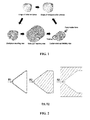
- FIG. 1 schematically illustrates a punch and a metal die used in a severe plastic deformation process according to the present invention and process steps thereof
- FIG. 2 is a cross-sectional view of the metal die, the punch and a workpiece used in an example of the present invention
- FIG. 3(A) is a photograph showing a conic metal pipe which has not been subjected to a severe plastic deformation process
- FIG. 3(B) is a photograph showing the conic metal pipe which has been subjected to the severe plastic deformation process.
- the severe plastic deformation process according to the present invention may include, as a whole, mounting a conic metal pipe workpiece on a punch and a metal die (first step), pressing the workpiece using the punch and the metal die (second step), and giving a twisting action to the conic metal pipe workpiece (third step).
- the first step for mounting the conic metal pipe workpiece on the punch and the metal die is performed in such a way that the punch which is prepared to have a configuration corresponding to the internal configuration of the conic metal pipe workpiece is mounted in the conic metal pipe workpiece and then the conic metal pipe workpiece with the punch mounted therein is mounted in the metal die which is prepared to have a configuration corresponding to the external configuration of the conic metal pipe.
- the sequence of mounting the punch and the metal die may be changed depending on the design conditions of the metal die.
- the punch may be disposed in the conic metal pipe workpiece after the conic metal pipe workpiece is mounted in the metal die.
- the metal die may include therein an electric heating element so as to provide heat to the conic metal pipe workpiece according to processing conditions of the conic metal pipe workpiece.
- the second step is performed in such a way that a predetermined compressive force is applied to the conic metal pipe workpiece mounted in the metal die by pressing the punch mounted in the workpiece.
- the compressive force may be determined depending on the final thickness of the workpiece such that there is no occurrence of slip of the workpiece.
- the manner of applying the compressive force to the conic metal pipe workpiece may include moving the metal die while holding the punch or moving both the metal die and the punch in addition to moving the punch as described above.
- the third step is performed in such a way that the punch is rotated to give a twisting action to the conic metal pipe workpiece while applying a constant compressive force to the conic metal pipe workpiece. After the twisting procedure is completed, the compressive force applied to the workpiece is released and then the workpiece is removed from the metal die.
- a twisting force can be applied to the conic metal pipe workpiece while a frictional force occurring at the boundary surface between the conic metal pipe and the punch is considerably increased by applying a hydrostatic pressure to the workpiece, thereby causing the conic metal pipe to be efficiently subjected to a shear deformation without a slip phenomenon. Furthermore, the applied hydrostatic pressure and the shear deformation cause the fine microstructure of the conic metal pipe to have ultrafine crystal grains or nanocrystalline grains.
- the fine microstructure and mechanical properties of the conic metal pipe workpiece can be modified to have the desired conditions by controlling the compressive force applied to the conic metal pipe workpiece and the number of rotations of the punch.
- FIG. 2 is a cross-sectional view of the conic metal pipe workpiece, the metal die and the punch used in the embodiment of the present invention.
- a size and a material of the workpiece may be changed depending on the intended use, and the metal die and the punch are manufactured in accordance with the configuration of the workpiece.
- the tip of the punch has a predetermined radius of curvature such that the tip of the punch is less sharp than that of the tip of the workpiece (in other words, a radius of curvature of the tip of the punch is larger than that the tip of the workpiece). This is intended to prevent breakage of the tip region of the workpiece caused by concentration of stress at the tip region during the severe plastic deformation process.
- the workpiece was manufactured from pure copper to have the configuration as shown in FIG. 2 , subjected to a heat treatment at 600 °C for 2 hours and then slowly cooled in a heating furnace.
- the severe plastic deformation process was performed at room temperature in such a way that the punch was rotated one revolution at 1 rpm of revolution speed while applying 80 ton of pressure to the punch.
- FIG. 3 is a photograph showing two workpieces before and after being subjected to the severe plastic deformation process according to the embodiment of the present invention, in which FIG. 3(A) shows the workpiece which has not been subjected to the severe plastic deformation process and FIG. 3(B) shows the workpiece which has been subjected to the process. It is appreciated from the photograph that both the two workpieces before and after being subjected to the severe plastic deformation process are substantially identical to each other in configuration with the exception that a thickness of the workpiece is decreased from 1.2 mm to 0.96 mm due to the effect of the strong compressive force after the severe plastic deformation process.
- the thickness of the workpiece after being subjected to the severe plastic deformation process may be controlled by selection of the compressive force and the revolution speed of the punch.
- FIG. 4 shows results obtained from a hardness test which is performed for the purpose of ascertaining the variation of mechanical properties of the workpiece measured before and after being subjected to the severe plastic deformation process according to the embodiment of the present invention.
- the term "initial state” refers to a hardness value measured from the edge of the exterior surface toward the central axis of an initial workpiece which has been subjected to heat treatment
- the term “exterior” refers to a hardness value measured in the same manner as that in the "initial state” with respect to the workpiece which has been subjected to the severe plastic deformation process, as shown in FIG. 4(A)
- the term “interior” refers to a hardness measured on a cross section of the workpiece which has been subjected to the severe plastic deformation process, as shown in FIG. 4(B) .
- directions of the hardness measurement are as illustrated in FIGS. 4A and 4B , and the interval between measurement points is 1 mm.
- a hardness value of a workpiece which had been subjected to the severe plastic deformation process was considerably increased to higher than 53 of the average hardness value (Hv) of the workpiece in its initial state, and more specifically a maximum hardness of the workpiece, which had been subjected to the severe plastic deformation process one time, was increased to 140 Hv. It is appreciated that the workpiece was evenly hardened throughout its entirety as proven from the fact that there was no perceptible difference between hardness values measured at an exterior area and an interior area of the workpiece.
- the evenly improved hardness can lead to improvement in mechanical properties such as strength and wear resistance of a workpiece. Consequently, since the severe plastic deformation process of the embodiment of the present invention can remarkably improve mechanical properties of a workpiece by means of a simple process while maintaining the shape of the conic metal pipe workpiece, the present invention can be appropriately applied to products such as bullets and missiles which require strong mechanical properties.
Landscapes
- Engineering & Computer Science (AREA)
- Chemical & Material Sciences (AREA)
- Mechanical Engineering (AREA)
- Crystallography & Structural Chemistry (AREA)
- Materials Engineering (AREA)
- Metallurgy (AREA)
- Organic Chemistry (AREA)
- Physics & Mathematics (AREA)
- Thermal Sciences (AREA)
- Shaping Metal By Deep-Drawing, Or The Like (AREA)
- Forging (AREA)
- Crystals, And After-Treatments Of Crystals (AREA)
Abstract
Description
- The present invention relates a method of performing a strong torsional plastic forming process to a conic metal pipe, and more particularly to a method of performing a strong torsional plastic forming process to a conic metal pipe, which provides the conic metal pipe with a shear deformation caused by shear stress resulting from application of a compressive force and a twisting force while substantially maintaining a shape of the conic metal pipe, thereby causing a fine microstructure of the conic metal pipe to have ultrafine crystal grains or nanocrystalline grains and thus improving mechanical properties of the conic metal pipe.
- A conic metal pipe is used in various industrial fields such as fields of manufacturing head parts of bullets or missiles, components of vehicles such as aircraft and automobiles, kitchen instruments and heating instruments. Such a conic metal pipe has been conventionally worked into a predetermined configuration through a "Metal spinning" technique.
- However, because the "Metal spinning" technique is a metallic working process which is chiefly intended to control configurations of workpieces, it has little relevance to improvement of mechanical properties such as control of fine microstructure. Furthermore, according to the "Metal spinning" technique, because deformation caused by high pressure applied from a metal tool is concentrated to a surface of a metal pipe workpiece, there is a problem in that a great difference between mechanical properties of internal and exterior areas of the worked metal pipe occurs.
- A metal material begins to form dislocation cells having small boundary angles when it is subjected to plastic deformation, and crystal grain boundary angles of sub-grains increase and crystal grains increasingly become fine as the amount of plastic deformation increases. Therefore, when metal material is highly deformed and thus crystal grains thereof become ultrafine grains or nanocrystalline grains, the deformed metal material has considerably improved mechanical properties (yield strength, tensile strength, hardness, wear resistance, superplasticity and the like) compared to a metal material which is not deformed. Accordingly, there is a need for a working process for producing a metal material having ultrafine crystal grains/nanocrystalline grains, rather than a conventional working process which is designed to mainly change a shape of the metal material.
- The formation of ultrafine crystal grains/nanocrystalline grains is affected by an amount of plastic deformation such as compressive deformation, tensile deformation and shear deformation which a workpiece undergoes. In addition, it is critical to design a metal die which maintains the substantially same shape before and after being subjected to a forming process, such that even when a workpiece undergoes a large amount of deformation the die maintains its shape, so as to allow the execution of repeated processes.
- Working processes, which meet the above requirements and have been developed to date, may include Equal Channel Angular pressing (ECAP), High-Pressure Torsion (HPT), Accumulative roll Bonding (ARB), Equal Channel Angular Rolling (ECAR) and the like.
- However, a working process which can give a severe plastic deformation to conic metal pipe in accordance with a configuration of the conic metal pipe, has not yet been developed, and thus there is a need for development of this kind of working process.
- Accordingly, an object of the present invention is to provide a method of performing a severe plastic deformation process to a conic metal pipe, which can substantially maintain a shape of the conic metal pipe to allow the conic metal pipe to be subjected to a large deforming process and which can cause a fine microstructure of the conic metal pipe to have ultrafine crystal grains or nanocrystalline grains to substantially improve mechanical properties of the conic metal pipe.
- In order to accomplish the above object, the present invention provides a method of performing a strong torsional plastic forming process to a conic metal pipe, including: mounting a punch having a configuration corresponding to an interior configuration of the conic metal pipe in the conic metal pipe; mounting a metal die having a configuration corresponding to an exterior configuration of the conic metal pipe on the conic metal pipe; and concurrently applying compressive and twisting forces to the conic metal pipe through the punch and the metal die to cause shear deformation of the conic metal pipe, thus enabling a fine microstructure of the conic metal pipe to have ultrafine crystal grains or nanocrystalline grains.
- In an aspect of the present invention, the shear deformation may be obtained by pressing the punch against the metal die and rotating the punch. In contrast, the twisting force may be applied by rotating the metal die while pushing the metal die or rotating the punch and the metal die in directions opposite to each other (for example, rotating the punch in a clockwise direction while rotating the metal die in a counterclockwise direction).
- In an aspect of the present invention, an amount of the shear deformation may be controlled by adjustment of a compressive force and a number of revolutions of the punch. When the punch and the metal die are concurrently rotated, the amount of the shear deformation may be controlled by adjustment of the metal die alone or both the punch and the metal die.
- In an aspect of the present invention, a higher compressive force may be applied to a central area of the conic metal pipe so as to cause the fine microstructure of the central area to have ultrafine crystal grains or nanocrystalline grains.
- In an aspect of the present invention, it is preferred that shape of the conic metal pipe which is not subjected to the strong torsional plastic forming process is substantially equal to a shape of the conic metal pipe which is subjected to the strong torsional plastic forming process. Consequently, repeated deformation can be applied to the conic metal pipe using the same punch and metal die, and thus a large amount of deformation can be applied.
- In an aspect of the present invention, one or both of the metal die and the punch may include a heating element to control a process temperature. Consequently, the conic metal pipe can be worked at an appropriate process temperature according to material of the metal pipe, and thus fine microstructure of the metal pipe can be controlled thus improving efficiency of process. Alternatively, the heating element may be provided outside rather than in the metal die or the punch.
- In an aspect of the present invention, a radius of curvature of a tip of the punch may be larger than that of a tip of the workpiece. Consequently, a thickness of the conic metal pipe can be evenly maintained along a height direction thereof, and thus concentration of stress can be prevented thereby preventing breakage of the conic metal pipe.
- According to the method of the present invention, maintenance of the conical shape enables a conic metal pipe to be subjected to great shear and compressive deformation without loss of material, thus causing a fine microstructure of the conic metal pipe to have ultrafine crystal grains or nanocrystalline grains. Consequently, mechanical properties of the conic metal pipe are remarkably increased, thus providing the conic metal pipe satisfying various mechanical property requirements.
- Furthermore, since the method of the present invention enables the conical shape of the conic metal pipe to be consistently maintained before and after the plastic forming process, torsional deformation and mechanical properties can be controlled through the repeated process.
- Furthermore, according to the method of the present invention, an amount of deformation of a workpiece can be freely controlled by adjusting the number of revolution of the punch (or metal die) during to process, and it is thus easy to control mechanical properties and a fine microstructure of the conic metal pipe.
-
-
FIG. 1 schematically illustrates a punch and a metal die used in a severe plastic deformation process according to the present invention and process steps thereof; -
FIG. 2 is a cross-sectional view of the metal die, the punch and a workpiece used in an example of the present invention; -
FIG. 3 (A) is a photograph showing a conic metal pipe which is not subjected to a severe plastic deformation process, andFIG. 3(B) is a photograph showing the conic metal pipe which has been subjected to the severe plastic deformation process; and -
FIG. 4 shows results obtained from a hardness test which is performed before and after being subjected to the severe plastic deformation process according to the embodiment of the present invention. -
FIG. 1 schematically illustrates a punch and a metal die used in a severe plastic deformation process according to the present invention and process steps thereof,FIG. 2 is a cross-sectional view of the metal die, the punch and a workpiece used in an example of the present invention,FIG. 3(A) is a photograph showing a conic metal pipe which has not been subjected to a severe plastic deformation process, andFIG. 3(B) is a photograph showing the conic metal pipe which has been subjected to the severe plastic deformation process. - The manufacturing process according to the present invention will now be specifically described with reference to the accompanying drawings. The severe plastic deformation process according to the present invention may include, as a whole, mounting a conic metal pipe workpiece on a punch and a metal die (first step), pressing the workpiece using the punch and the metal die (second step), and giving a twisting action to the conic metal pipe workpiece (third step).
- As illustrated in
FIGS. 1 and 2 , the first step for mounting the conic metal pipe workpiece on the punch and the metal die is performed in such a way that the punch which is prepared to have a configuration corresponding to the internal configuration of the conic metal pipe workpiece is mounted in the conic metal pipe workpiece and then the conic metal pipe workpiece with the punch mounted therein is mounted in the metal die which is prepared to have a configuration corresponding to the external configuration of the conic metal pipe. In this context, the sequence of mounting the punch and the metal die may be changed depending on the design conditions of the metal die. In other words, the punch may be disposed in the conic metal pipe workpiece after the conic metal pipe workpiece is mounted in the metal die. Furthermore, the metal die may include therein an electric heating element so as to provide heat to the conic metal pipe workpiece according to processing conditions of the conic metal pipe workpiece. - The second step is performed in such a way that a predetermined compressive force is applied to the conic metal pipe workpiece mounted in the metal die by pressing the punch mounted in the workpiece. At this point, the compressive force may be determined depending on the final thickness of the workpiece such that there is no occurrence of slip of the workpiece. The manner of applying the compressive force to the conic metal pipe workpiece may include moving the metal die while holding the punch or moving both the metal die and the punch in addition to moving the punch as described above.
- The third step is performed in such a way that the punch is rotated to give a twisting action to the conic metal pipe workpiece while applying a constant compressive force to the conic metal pipe workpiece. After the twisting procedure is completed, the compressive force applied to the workpiece is released and then the workpiece is removed from the metal die.
- According to the severe plastic deformation process of the present invention, a twisting force can be applied to the conic metal pipe workpiece while a frictional force occurring at the boundary surface between the conic metal pipe and the punch is considerably increased by applying a hydrostatic pressure to the workpiece, thereby causing the conic metal pipe to be efficiently subjected to a shear deformation without a slip phenomenon. Furthermore, the applied hydrostatic pressure and the shear deformation cause the fine microstructure of the conic metal pipe to have ultrafine crystal grains or nanocrystalline grains.
- In the severe plastic deformation process according to the present invention, the fine microstructure and mechanical properties of the conic metal pipe workpiece can be modified to have the desired conditions by controlling the compressive force applied to the conic metal pipe workpiece and the number of rotations of the punch.
- The present invention will now be described in detail with reference to a preferred embodiment thereof.
-
FIG. 2 is a cross-sectional view of the conic metal pipe workpiece, the metal die and the punch used in the embodiment of the present invention. A size and a material of the workpiece may be changed depending on the intended use, and the metal die and the punch are manufactured in accordance with the configuration of the workpiece. - In this embodiment of the present invention, the tip of the punch has a predetermined radius of curvature such that the tip of the punch is less sharp than that of the tip of the workpiece (in other words, a radius of curvature of the tip of the punch is larger than that the tip of the workpiece). This is intended to prevent breakage of the tip region of the workpiece caused by concentration of stress at the tip region during the severe plastic deformation process.
- In the severe plastic deformation process according to this embodiment of the present invention, the workpiece was manufactured from pure copper to have the configuration as shown in
FIG. 2 , subjected to a heat treatment at 600 °C for 2 hours and then slowly cooled in a heating furnace. The severe plastic deformation process was performed at room temperature in such a way that the punch was rotated one revolution at 1 rpm of revolution speed while applying 80 ton of pressure to the punch. -
FIG. 3 is a photograph showing two workpieces before and after being subjected to the severe plastic deformation process according to the embodiment of the present invention, in whichFIG. 3(A) shows the workpiece which has not been subjected to the severe plastic deformation process andFIG. 3(B) shows the workpiece which has been subjected to the process. It is appreciated from the photograph that both the two workpieces before and after being subjected to the severe plastic deformation process are substantially identical to each other in configuration with the exception that a thickness of the workpiece is decreased from 1.2 mm to 0.96 mm due to the effect of the strong compressive force after the severe plastic deformation process. The thickness of the workpiece after being subjected to the severe plastic deformation process may be controlled by selection of the compressive force and the revolution speed of the punch. -
FIG. 4 shows results obtained from a hardness test which is performed for the purpose of ascertaining the variation of mechanical properties of the workpiece measured before and after being subjected to the severe plastic deformation process according to the embodiment of the present invention. - In the drawing, the term "initial state" refers to a hardness value measured from the edge of the exterior surface toward the central axis of an initial workpiece which has been subjected to heat treatment, the term "exterior" refers to a hardness value measured in the same manner as that in the "initial state" with respect to the workpiece which has been subjected to the severe plastic deformation process, as shown in
FIG. 4(A) , and the term "interior" refers to a hardness measured on a cross section of the workpiece which has been subjected to the severe plastic deformation process, as shown inFIG. 4(B) . In this respect, directions of the hardness measurement are as illustrated inFIGS. 4A and 4B , and the interval between measurement points is 1 mm. - As seen from
FIG. 4 , a hardness value of a workpiece which had been subjected to the severe plastic deformation process was considerably increased to higher than 53 of the average hardness value (Hv) of the workpiece in its initial state, and more specifically a maximum hardness of the workpiece, which had been subjected to the severe plastic deformation process one time, was increased to 140 Hv. It is appreciated that the workpiece was evenly hardened throughout its entirety as proven from the fact that there was no perceptible difference between hardness values measured at an exterior area and an interior area of the workpiece. - The evenly improved hardness can lead to improvement in mechanical properties such as strength and wear resistance of a workpiece. Consequently, since the severe plastic deformation process of the embodiment of the present invention can remarkably improve mechanical properties of a workpiece by means of a simple process while maintaining the shape of the conic metal pipe workpiece, the present invention can be appropriately applied to products such as bullets and missiles which require strong mechanical properties.
Claims (9)
- A method of performing a strong torsional plastic forming process to a conic metal pipe, comprising:mounting a punch having a configuration corresponding to an interior configuration of the conic metal pipe in the conic metal pipe;mounting a metal die having a configuration corresponding to an exterior configuration of the conic metal pipe on the conic metal pipe; andconcurrently applying compressive and twisting forces to the conic metal pipe through the punch and the metal die to cause shear deformation of the conic metal pipe, thus enabling a fine microstructure of the conic metal pipe to have ultrafine crystal grains or nanocrystalline grains.
- A method according to Claim 1, wherein the shear deformation is obtained by pressing the punch against the metal die and rotating the punch.
- A method according to Claim 2, wherein an amount of the shear deformation is controlled by adjustment of a compressive force and a number of revolutions of the punch.
- A method according to any of Claims 1 to 3, wherein a higher compressive force is applied to a central area of the conic metal pipe so as to cause the fine microstructure of the central area to have ultrafine crystal grains or nanocrystalline grains.
- A method according to any of Claims 1 to 3, wherein a shape of the conic metal pipe which has not been subjected to the strong torsional plastic forming process is substantially equal to a shape of a conic metal pipe which has been subjected to the strong torsional plastic forming process with the exception of thickness.
- A method according to any of Claims 1 to 3, wherein the metal die includes a heating element to control a process temperature.
- A method according to any of Claims 1 to 3, wherein the punch includes a heating element to control a process temperature.
- A method according to Claim 1, wherein the metal die is rotatable alone or together with the punch.
- A method according to Claim 1, wherein a radius of curvature of a tip of the punch is larger than that of a tip of the workpiece.
Applications Claiming Priority (2)
| Application Number | Priority Date | Filing Date | Title |
|---|---|---|---|
| KR1020110136224A KR101323168B1 (en) | 2011-12-16 | 2011-12-16 | Torsional severe plastic deformation method for conical tube metals |
| PCT/KR2012/010335 WO2013089374A1 (en) | 2011-12-16 | 2012-11-30 | Torsional extreme-plastic processing method of conic metal pipe |
Publications (2)
| Publication Number | Publication Date |
|---|---|
| EP2808101A1 true EP2808101A1 (en) | 2014-12-03 |
| EP2808101A4 EP2808101A4 (en) | 2015-10-21 |
Family
ID=48612774
Family Applications (1)
| Application Number | Title | Priority Date | Filing Date |
|---|---|---|---|
| EP12856595.9A Withdrawn EP2808101A4 (en) | 2011-12-16 | 2012-11-30 | Torsional extreme-plastic processing method of conic metal pipe |
Country Status (6)
| Country | Link |
|---|---|
| US (1) | US9447487B2 (en) |
| EP (1) | EP2808101A4 (en) |
| JP (1) | JP6077000B2 (en) |
| KR (1) | KR101323168B1 (en) |
| CN (1) | CN104010744B (en) |
| WO (1) | WO2013089374A1 (en) |
Families Citing this family (9)
| Publication number | Priority date | Publication date | Assignee | Title |
|---|---|---|---|---|
| KR101593836B1 (en) | 2014-11-03 | 2016-02-12 | 포항공과대학교 산학협력단 | Apparatus and method for improving the strength of metallic materials |
| KR101680461B1 (en) | 2015-03-30 | 2016-11-28 | 포항공과대학교 산학협력단 | Die for torsional severe plastic deformation method for conical tube metals |
| KR20170109109A (en) * | 2016-03-17 | 2017-09-28 | 포항공과대학교 산학협력단 | Method for Enhancing Anti-Fouling Properties of High Entropy Alloys |
| KR101903236B1 (en) | 2016-08-23 | 2018-11-13 | 국방과학연구소 | Localized torsional severe plastic deformation method for conical tube metals |
| KR101866127B1 (en) | 2017-03-20 | 2018-06-08 | 포항공과대학교 산학협력단 | Simple torsion-based severe plastic deformation of metallic bar enhanced mechanical properties by surface abrasion |
| CN110378053B (en) * | 2019-07-25 | 2020-10-30 | 东北大学 | Determination method for optimal straightening curvature of circular arc roll shape in two-slanted roll straightening process for pipes |
| CN112474873B (en) * | 2020-12-02 | 2022-03-01 | 江阴市丰厚管件有限公司 | Manufacturing method of seamless reducer pipe |
| CN116638021A (en) * | 2023-05-16 | 2023-08-25 | 武汉理工大学 | A large conical cylinder electromagnetic impact composite roll forming equipment and method |
| CN119327975B (en) * | 2024-12-24 | 2025-03-18 | 北京理工大学 | TiZrNb-based high-entropy alloy conical part forming method |
Family Cites Families (22)
| Publication number | Priority date | Publication date | Assignee | Title |
|---|---|---|---|---|
| BE791879A (en) * | 1971-11-25 | 1973-05-24 | Scal Gp Condit Aluminium | CONICAL FLEXIBLE TUBES MANUFACTURING PROCESS |
| FR2644714A1 (en) * | 1989-03-22 | 1990-09-28 | Commissariat Energie Atomique | PROCESS FOR OBTAINING COPPER LARGE SIZE PARTS AND VERY FINE STRUCTURE FROM A CONTINUOUSLY CONTINUOUS LOPIN |
| EP0711210B1 (en) * | 1994-05-30 | 2000-08-23 | Andrzej Korbel | Method of plastic forming of materials |
| JPH0810833A (en) * | 1994-06-27 | 1996-01-16 | Nippon Steel Metal Prod Co Ltd | Tapered tube manufacturing equipment |
| CN1060694C (en) * | 1996-02-13 | 2001-01-17 | 张荣发 | Forging process for inner and outer rings of conical bearings |
| JP2001321825A (en) * | 2000-05-18 | 2001-11-20 | Toto Ltd | Metal material processing method and apparatus |
| JP3616591B2 (en) * | 2001-09-06 | 2005-02-02 | 独立行政法人科学技術振興機構 | Crystal grain refinement method and grain refiner for metal material |
| JP2004174563A (en) | 2002-11-27 | 2004-06-24 | Mitsubishi Heavy Ind Ltd | Method and equipment for controlling structure of metallic tube and method for producing metallic sheet |
| US6866180B2 (en) * | 2003-02-18 | 2005-03-15 | Rockwell Scientific Licensing, Llc | Thick-section metal forming via friction stir processing |
| JP4305151B2 (en) * | 2003-05-16 | 2009-07-29 | 晋 水沼 | Material torsion extrusion process |
| US7096705B2 (en) * | 2003-10-20 | 2006-08-29 | Segal Vladimir M | Shear-extrusion method |
| KR100541221B1 (en) * | 2004-01-08 | 2006-01-11 | 충남대학교산학협력단 | Torsional extrusion die and surface hardening method of metal material using the die |
| CN100386466C (en) * | 2006-03-22 | 2008-05-07 | 西安建筑科技大学 | Method and device for preparing fine-grained materials by cyclic extrusion with continuously variable cross-section |
| CN1994605A (en) * | 2006-08-22 | 2007-07-11 | 陈波 | Cold extrusion processing technique for high-strength conical vertical tube of motorcycle steel column |
| JP2009018342A (en) * | 2007-06-11 | 2009-01-29 | Sango Co Ltd | Different diameter part forming method of work |
| JP5288437B2 (en) * | 2007-08-13 | 2013-09-11 | 善治 堀田 | Strain applying method and strain applying device |
| JP2009203508A (en) * | 2008-02-27 | 2009-09-10 | Aisin Seiki Co Ltd | Crystal grain micronizing method and crystal grain micronizing device |
| JP2010105005A (en) * | 2008-10-29 | 2010-05-13 | Aisin Seiki Co Ltd | Metallic material-micronizing device |
| KR101202852B1 (en) * | 2010-04-15 | 2012-11-20 | 한국생산기술연구원 | Method and apparatus for extrusion with monotonic torsion |
| CN102189706B (en) | 2011-01-28 | 2014-10-08 | 南京理工大学 | High-pressure shearing deformation method and device for tubular materials |
| CN102836939B (en) * | 2011-06-24 | 2015-03-25 | 深圳富泰宏精密工业有限公司 | Forging method of aluminum or aluminum alloy |
| CN102500632B (en) * | 2011-09-30 | 2014-11-05 | 南京理工大学 | Method for realizing high-pressure shearing of pipes according to wedge principle and device utilizing method |
-
2011
- 2011-12-16 KR KR1020110136224A patent/KR101323168B1/en not_active Expired - Fee Related
-
2012
- 2012-11-30 EP EP12856595.9A patent/EP2808101A4/en not_active Withdrawn
- 2012-11-30 US US14/365,837 patent/US9447487B2/en not_active Expired - Fee Related
- 2012-11-30 CN CN201280062230.XA patent/CN104010744B/en not_active Expired - Fee Related
- 2012-11-30 JP JP2014547087A patent/JP6077000B2/en not_active Expired - Fee Related
- 2012-11-30 WO PCT/KR2012/010335 patent/WO2013089374A1/en not_active Ceased
Also Published As
| Publication number | Publication date |
|---|---|
| KR101323168B1 (en) | 2013-11-05 |
| EP2808101A4 (en) | 2015-10-21 |
| JP2015508334A (en) | 2015-03-19 |
| US9447487B2 (en) | 2016-09-20 |
| WO2013089374A1 (en) | 2013-06-20 |
| US20140331733A1 (en) | 2014-11-13 |
| CN104010744B (en) | 2016-01-20 |
| CN104010744A (en) | 2014-08-27 |
| JP6077000B2 (en) | 2017-02-08 |
| KR20130068827A (en) | 2013-06-26 |
Similar Documents
| Publication | Publication Date | Title |
|---|---|---|
| US9447487B2 (en) | Torsional extreme-plastic processing method of conic metal pipe | |
| RU2638139C2 (en) | Forging in the open stamp with separate passages of difficult for forging and sensitive to the trajectory of deformation of alloys based on titanium and based on nickel | |
| Chan et al. | Meso-scaled progressive forming of bulk cylindrical and flanged parts using sheet metal | |
| Xu et al. | Effect of grain size and specimen dimensions on micro-forming of high purity aluminum | |
| Fu et al. | Micro-scaled progressive forming of bulk micropart via directly using sheet metals | |
| JP2009172657A (en) | High performance magnesium alloy member and manufacturing method thereof | |
| KR101210889B1 (en) | Severe plastic deformation system and method for working wire rod using the same | |
| US8910409B1 (en) | System and method of producing autofrettage in tubular components using a flowforming process | |
| CN103981472B (en) | A kind of Equal-channel Angular Pressing prepares the method for the pure titanium of Ultra-fine Grained | |
| Hezam et al. | Development of a new process for producing deep square cups through conical dies | |
| CN103492098A (en) | Severe plastic deformation treatment method and equipment | |
| CN106862863A (en) | A kind of preparation processing method of the ultra-thin titanium alloy shell of great diameter and long | |
| CN106994583A (en) | The manufacture method of Mg alloy thin wall forging-ring | |
| Salishchev et al. | Formation of submicrocrystalline structure in large-size billets and sheets out of titanium alloys | |
| Rusz et al. | Possibilities of application methods DRECE in forming of non-ferrous metals | |
| EP3189911A1 (en) | Ring material and method for manufacturing molded ring | |
| KR101465090B1 (en) | Grain refining method for tubular metallic material | |
| Bhatt et al. | Investigation of effect of material properties on forces during flow forming process | |
| Kumar et al. | Numerical simulation of Al1070 alloy through hybrid SPD process | |
| Kwak et al. | Processing and mechanical properties of fine grained magnesium by equal channel angular pressing | |
| KR20240166857A (en) | Torsional severe plastic deformation method for conical tube metals | |
| RU2486275C1 (en) | Method to produce ultra-fine grain blank of gte blade of titanium alloys | |
| CN103469131B (en) | A kind of intermediate blank preparation method analyzing Magnesium Alloy performance inhomogeneities | |
| Chang et al. | Influence of grain size and temperature on micro upsetting of copper | |
| US10661335B2 (en) | Localized torsional severe plastic deformation method for conical tube metals |
Legal Events
| Date | Code | Title | Description |
|---|---|---|---|
| PUAI | Public reference made under article 153(3) epc to a published international application that has entered the european phase |
Free format text: ORIGINAL CODE: 0009012 |
|
| 17P | Request for examination filed |
Effective date: 20140715 |
|
| AK | Designated contracting states |
Kind code of ref document: A1 Designated state(s): AL AT BE BG CH CY CZ DE DK EE ES FI FR GB GR HR HU IE IS IT LI LT LU LV MC MK MT NL NO PL PT RO RS SE SI SK SM TR |
|
| DAX | Request for extension of the european patent (deleted) | ||
| RA4 | Supplementary search report drawn up and despatched (corrected) |
Effective date: 20150923 |
|
| RIC1 | Information provided on ipc code assigned before grant |
Ipc: C21D 7/02 20060101ALI20150911BHEP Ipc: B21C 23/01 20060101ALI20150911BHEP Ipc: B21D 7/00 20060101ALI20150911BHEP Ipc: B21D 11/02 20060101AFI20150911BHEP Ipc: B21D 11/14 20060101ALI20150911BHEP |
|
| STAA | Information on the status of an ep patent application or granted ep patent |
Free format text: STATUS: EXAMINATION IS IN PROGRESS |
|
| 17Q | First examination report despatched |
Effective date: 20170410 |
|
| STAA | Information on the status of an ep patent application or granted ep patent |
Free format text: STATUS: THE APPLICATION IS DEEMED TO BE WITHDRAWN |
|
| 18D | Application deemed to be withdrawn |
Effective date: 20170822 |