EP2806165A1 - Scrollkompressor und CO2-Fahrzeugklimaanlage mit einem Scrollkompressor - Google Patents
Scrollkompressor und CO2-Fahrzeugklimaanlage mit einem Scrollkompressor Download PDFInfo
- Publication number
- EP2806165A1 EP2806165A1 EP13168737.8A EP13168737A EP2806165A1 EP 2806165 A1 EP2806165 A1 EP 2806165A1 EP 13168737 A EP13168737 A EP 13168737A EP 2806165 A1 EP2806165 A1 EP 2806165A1
- Authority
- EP
- European Patent Office
- Prior art keywords
- spiral
- counter
- scroll compressor
- pressure chamber
- compressor according
- Prior art date
- Legal status (The legal status is an assumption and is not a legal conclusion. Google has not performed a legal analysis and makes no representation as to the accuracy of the status listed.)
- Granted
Links
- 238000006073 displacement reaction Methods 0.000 claims abstract description 63
- 239000003507 refrigerant Substances 0.000 claims abstract description 14
- 238000004378 air conditioning Methods 0.000 claims description 8
- 239000012530 fluid Substances 0.000 claims description 3
- 238000004891 communication Methods 0.000 claims description 2
- 238000004804 winding Methods 0.000 claims description 2
- 238000007789 sealing Methods 0.000 description 9
- 229910001220 stainless steel Inorganic materials 0.000 description 6
- 239000010935 stainless steel Substances 0.000 description 6
- 230000008901 benefit Effects 0.000 description 5
- 230000006835 compression Effects 0.000 description 5
- 238000007906 compression Methods 0.000 description 5
- 238000010276 construction Methods 0.000 description 4
- 239000003638 chemical reducing agent Substances 0.000 description 3
- 238000010586 diagram Methods 0.000 description 3
- 230000010349 pulsation Effects 0.000 description 3
- 240000006829 Ficus sundaica Species 0.000 description 2
- XAGFODPZIPBFFR-UHFFFAOYSA-N aluminium Chemical compound [Al] XAGFODPZIPBFFR-UHFFFAOYSA-N 0.000 description 2
- 229910052782 aluminium Inorganic materials 0.000 description 2
- 230000008878 coupling Effects 0.000 description 2
- 238000010168 coupling process Methods 0.000 description 2
- 238000005859 coupling reaction Methods 0.000 description 2
- 230000009977 dual effect Effects 0.000 description 2
- 238000005538 encapsulation Methods 0.000 description 2
- 238000010438 heat treatment Methods 0.000 description 2
- 238000009434 installation Methods 0.000 description 2
- 238000009413 insulation Methods 0.000 description 2
- 230000009467 reduction Effects 0.000 description 2
- 229910000831 Steel Inorganic materials 0.000 description 1
- 230000004308 accommodation Effects 0.000 description 1
- 230000015572 biosynthetic process Effects 0.000 description 1
- 230000008859 change Effects 0.000 description 1
- 238000002485 combustion reaction Methods 0.000 description 1
- 230000003750 conditioning effect Effects 0.000 description 1
- 238000001816 cooling Methods 0.000 description 1
- 125000004122 cyclic group Chemical group 0.000 description 1
- 238000013016 damping Methods 0.000 description 1
- 230000000694 effects Effects 0.000 description 1
- 238000004880 explosion Methods 0.000 description 1
- 210000003746 feather Anatomy 0.000 description 1
- 230000006872 improvement Effects 0.000 description 1
- 230000000977 initiatory effect Effects 0.000 description 1
- 238000004519 manufacturing process Methods 0.000 description 1
- 238000005192 partition Methods 0.000 description 1
- 230000002093 peripheral effect Effects 0.000 description 1
- 238000005057 refrigeration Methods 0.000 description 1
- 239000010959 steel Substances 0.000 description 1
- 238000010792 warming Methods 0.000 description 1
Images


Classifications
-
- F—MECHANICAL ENGINEERING; LIGHTING; HEATING; WEAPONS; BLASTING
- F04—POSITIVE - DISPLACEMENT MACHINES FOR LIQUIDS; PUMPS FOR LIQUIDS OR ELASTIC FLUIDS
- F04C—ROTARY-PISTON, OR OSCILLATING-PISTON, POSITIVE-DISPLACEMENT MACHINES FOR LIQUIDS; ROTARY-PISTON, OR OSCILLATING-PISTON, POSITIVE-DISPLACEMENT PUMPS
- F04C27/00—Sealing arrangements in rotary-piston pumps specially adapted for elastic fluids
- F04C27/005—Axial sealings for working fluid
-
- F—MECHANICAL ENGINEERING; LIGHTING; HEATING; WEAPONS; BLASTING
- F04—POSITIVE - DISPLACEMENT MACHINES FOR LIQUIDS; PUMPS FOR LIQUIDS OR ELASTIC FLUIDS
- F04C—ROTARY-PISTON, OR OSCILLATING-PISTON, POSITIVE-DISPLACEMENT MACHINES FOR LIQUIDS; ROTARY-PISTON, OR OSCILLATING-PISTON, POSITIVE-DISPLACEMENT PUMPS
- F04C29/00—Component parts, details or accessories of pumps or pumping installations, not provided for in groups F04C18/00 - F04C28/00
- F04C29/0042—Driving elements, brakes, couplings, transmissions specially adapted for pumps
- F04C29/005—Means for transmitting movement from the prime mover to driven parts of the pump, e.g. clutches, couplings, transmissions
- F04C29/0057—Means for transmitting movement from the prime mover to driven parts of the pump, e.g. clutches, couplings, transmissions for eccentric movement
-
- F—MECHANICAL ENGINEERING; LIGHTING; HEATING; WEAPONS; BLASTING
- F04—POSITIVE - DISPLACEMENT MACHINES FOR LIQUIDS; PUMPS FOR LIQUIDS OR ELASTIC FLUIDS
- F04C—ROTARY-PISTON, OR OSCILLATING-PISTON, POSITIVE-DISPLACEMENT MACHINES FOR LIQUIDS; ROTARY-PISTON, OR OSCILLATING-PISTON, POSITIVE-DISPLACEMENT PUMPS
- F04C18/00—Rotary-piston pumps specially adapted for elastic fluids
- F04C18/02—Rotary-piston pumps specially adapted for elastic fluids of arcuate-engagement type, i.e. with circular translatory movement of co-operating members, each member having the same number of teeth or tooth-equivalents
- F04C18/0207—Rotary-piston pumps specially adapted for elastic fluids of arcuate-engagement type, i.e. with circular translatory movement of co-operating members, each member having the same number of teeth or tooth-equivalents both members having co-operating elements in spiral form
- F04C18/0215—Rotary-piston pumps specially adapted for elastic fluids of arcuate-engagement type, i.e. with circular translatory movement of co-operating members, each member having the same number of teeth or tooth-equivalents both members having co-operating elements in spiral form where only one member is moving
-
- F—MECHANICAL ENGINEERING; LIGHTING; HEATING; WEAPONS; BLASTING
- F04—POSITIVE - DISPLACEMENT MACHINES FOR LIQUIDS; PUMPS FOR LIQUIDS OR ELASTIC FLUIDS
- F04C—ROTARY-PISTON, OR OSCILLATING-PISTON, POSITIVE-DISPLACEMENT MACHINES FOR LIQUIDS; ROTARY-PISTON, OR OSCILLATING-PISTON, POSITIVE-DISPLACEMENT PUMPS
- F04C18/00—Rotary-piston pumps specially adapted for elastic fluids
- F04C18/02—Rotary-piston pumps specially adapted for elastic fluids of arcuate-engagement type, i.e. with circular translatory movement of co-operating members, each member having the same number of teeth or tooth-equivalents
- F04C18/0207—Rotary-piston pumps specially adapted for elastic fluids of arcuate-engagement type, i.e. with circular translatory movement of co-operating members, each member having the same number of teeth or tooth-equivalents both members having co-operating elements in spiral form
- F04C18/0246—Details concerning the involute wraps or their base, e.g. geometry
- F04C18/0253—Details concerning the base
-
- F—MECHANICAL ENGINEERING; LIGHTING; HEATING; WEAPONS; BLASTING
- F04—POSITIVE - DISPLACEMENT MACHINES FOR LIQUIDS; PUMPS FOR LIQUIDS OR ELASTIC FLUIDS
- F04C—ROTARY-PISTON, OR OSCILLATING-PISTON, POSITIVE-DISPLACEMENT MACHINES FOR LIQUIDS; ROTARY-PISTON, OR OSCILLATING-PISTON, POSITIVE-DISPLACEMENT PUMPS
- F04C29/00—Component parts, details or accessories of pumps or pumping installations, not provided for in groups F04C18/00 - F04C28/00
- F04C29/02—Lubrication; Lubricant separation
- F04C29/026—Lubricant separation
-
- F—MECHANICAL ENGINEERING; LIGHTING; HEATING; WEAPONS; BLASTING
- F04—POSITIVE - DISPLACEMENT MACHINES FOR LIQUIDS; PUMPS FOR LIQUIDS OR ELASTIC FLUIDS
- F04C—ROTARY-PISTON, OR OSCILLATING-PISTON, POSITIVE-DISPLACEMENT MACHINES FOR LIQUIDS; ROTARY-PISTON, OR OSCILLATING-PISTON, POSITIVE-DISPLACEMENT PUMPS
- F04C29/00—Component parts, details or accessories of pumps or pumping installations, not provided for in groups F04C18/00 - F04C28/00
- F04C29/12—Arrangements for admission or discharge of the working fluid, e.g. constructional features of the inlet or outlet
- F04C29/124—Arrangements for admission or discharge of the working fluid, e.g. constructional features of the inlet or outlet with inlet and outlet valves specially adapted for rotary or oscillating piston pumps
- F04C29/126—Arrangements for admission or discharge of the working fluid, e.g. constructional features of the inlet or outlet with inlet and outlet valves specially adapted for rotary or oscillating piston pumps of the non-return type
-
- F—MECHANICAL ENGINEERING; LIGHTING; HEATING; WEAPONS; BLASTING
- F04—POSITIVE - DISPLACEMENT MACHINES FOR LIQUIDS; PUMPS FOR LIQUIDS OR ELASTIC FLUIDS
- F04C—ROTARY-PISTON, OR OSCILLATING-PISTON, POSITIVE-DISPLACEMENT MACHINES FOR LIQUIDS; ROTARY-PISTON, OR OSCILLATING-PISTON, POSITIVE-DISPLACEMENT PUMPS
- F04C2210/00—Fluid
- F04C2210/10—Fluid working
- F04C2210/1027—CO2
-
- F—MECHANICAL ENGINEERING; LIGHTING; HEATING; WEAPONS; BLASTING
- F04—POSITIVE - DISPLACEMENT MACHINES FOR LIQUIDS; PUMPS FOR LIQUIDS OR ELASTIC FLUIDS
- F04C—ROTARY-PISTON, OR OSCILLATING-PISTON, POSITIVE-DISPLACEMENT MACHINES FOR LIQUIDS; ROTARY-PISTON, OR OSCILLATING-PISTON, POSITIVE-DISPLACEMENT PUMPS
- F04C2210/00—Fluid
- F04C2210/26—Refrigerants with particular properties, e.g. HFC-134a
- F04C2210/261—Carbon dioxide (CO2)
-
- F—MECHANICAL ENGINEERING; LIGHTING; HEATING; WEAPONS; BLASTING
- F04—POSITIVE - DISPLACEMENT MACHINES FOR LIQUIDS; PUMPS FOR LIQUIDS OR ELASTIC FLUIDS
- F04C—ROTARY-PISTON, OR OSCILLATING-PISTON, POSITIVE-DISPLACEMENT MACHINES FOR LIQUIDS; ROTARY-PISTON, OR OSCILLATING-PISTON, POSITIVE-DISPLACEMENT PUMPS
- F04C2240/00—Components
- F04C2240/40—Electric motor
-
- F—MECHANICAL ENGINEERING; LIGHTING; HEATING; WEAPONS; BLASTING
- F04—POSITIVE - DISPLACEMENT MACHINES FOR LIQUIDS; PUMPS FOR LIQUIDS OR ELASTIC FLUIDS
- F04C—ROTARY-PISTON, OR OSCILLATING-PISTON, POSITIVE-DISPLACEMENT MACHINES FOR LIQUIDS; ROTARY-PISTON, OR OSCILLATING-PISTON, POSITIVE-DISPLACEMENT PUMPS
- F04C2240/00—Components
- F04C2240/80—Other components
- F04C2240/807—Balance weight, counterweight
-
- F—MECHANICAL ENGINEERING; LIGHTING; HEATING; WEAPONS; BLASTING
- F04—POSITIVE - DISPLACEMENT MACHINES FOR LIQUIDS; PUMPS FOR LIQUIDS OR ELASTIC FLUIDS
- F04C—ROTARY-PISTON, OR OSCILLATING-PISTON, POSITIVE-DISPLACEMENT MACHINES FOR LIQUIDS; ROTARY-PISTON, OR OSCILLATING-PISTON, POSITIVE-DISPLACEMENT PUMPS
- F04C23/00—Combinations of two or more pumps, each being of rotary-piston or oscillating-piston type, specially adapted for elastic fluids; Pumping installations specially adapted for elastic fluids; Multi-stage pumps specially adapted for elastic fluids
- F04C23/008—Hermetic pumps
-
- F—MECHANICAL ENGINEERING; LIGHTING; HEATING; WEAPONS; BLASTING
- F04—POSITIVE - DISPLACEMENT MACHINES FOR LIQUIDS; PUMPS FOR LIQUIDS OR ELASTIC FLUIDS
- F04C—ROTARY-PISTON, OR OSCILLATING-PISTON, POSITIVE-DISPLACEMENT MACHINES FOR LIQUIDS; ROTARY-PISTON, OR OSCILLATING-PISTON, POSITIVE-DISPLACEMENT PUMPS
- F04C28/00—Control of, monitoring of, or safety arrangements for, pumps or pumping installations specially adapted for elastic fluids
- F04C28/24—Control of, monitoring of, or safety arrangements for, pumps or pumping installations specially adapted for elastic fluids characterised by using valves controlling pressure or flow rate, e.g. discharge valves or unloading valves
- F04C28/26—Control of, monitoring of, or safety arrangements for, pumps or pumping installations specially adapted for elastic fluids characterised by using valves controlling pressure or flow rate, e.g. discharge valves or unloading valves using bypass channels
- F04C28/265—Control of, monitoring of, or safety arrangements for, pumps or pumping installations specially adapted for elastic fluids characterised by using valves controlling pressure or flow rate, e.g. discharge valves or unloading valves using bypass channels being obtained by displacing a lateral sealing face
Definitions
- the invention relates to a scroll compressor for a CO 2 vehicle air conditioning system, and a CO 2 vehicle air conditioning system with such a scroll compressor.
- Non-combustible refrigerants are used for the air conditioning of motor vehicles in order to avoid the risk of explosion inside the vehicle in the event of an accident.
- the refrigerants used so far are either already banned or at least classified as problematic because of their high global warming potential.
- CO 2 non-combustible refrigerant
- CO 2 air conditioners operate with high operating pressures, which make special demands on the strength and tightness of the system components. The advantage associated with the high operating pressure is that the higher density of CO 2 requires a smaller volume flow to provide a relatively high refrigeration capacity.
- a scroll compressor for a CO 2 vehicle air conditioner with the features of the preamble of claim 1 is made JP 2006/144635 A known.
- Such scroll compressors have variable speed electric drives to control the cooling capacity of the compressor.
- the invention has for its object to provide a scroll compressor for a CO 2 vehicle air conditioning, which is simple in construction and allows power control.
- the invention is also based on the object of specifying a CO 2 vehicle air conditioning system with such a scroll compressor.
- the object is achieved by a scroll compressor for a CO 2 vehicle air conditioner with the features of claim 1.
- the object is achieved by the subject matter of claim 15.
- the invention has several advantages.
- the use of a fixed drive, i.e., fixed, electric drive. constant speed allows cost-effective design compared to variable speed compressors.
- the power control is effected by the alternating movement of the counter-spiral relative to the displacement spiral in the axial direction.
- a pressure compensation gap is temporarily formed between the counter-spiral and the displacement spiral, so that compressed gas can flow radially outward from the chambers of the compressor which are located radially further inside. This reduces the pressure in the scroll compressor.
- the positive displacement spiral continues to run, so that a clutch for separating the power flow between the drive and the displacement spiral is not required.
- the scroll compressor according to the invention can therefore be designed clutchless.
- the design of the scroll compressor as a clutchless compressor leads to a significant reduction in the mass moment of inertia. Because the displacement spiral runs in the no-load condition, eliminates the starting torque in the scroll compressor according to the invention. In addition, the load on the rotating components is greatly reduced and the consumption is reduced.
- the scroll compressor according to the invention is very quiet and quiet.
- the alternating movement of the counter-spiral is effected by an axial release force and an opposite closing force.
- the axial release force is applied by a spring which is arranged between the displacement spiral and the counter-spiral.
- the release force lifts the counter-spiral from the positive displacement spiral so that the pressure equalization gap is created in between and the scroll compressor is switched off (open position).
- a piston is provided which engages next to the pressure chamber on the counter-spiral. The closing force brings the counter-spiral into contact with the displacement spiral.
- the pressure equalizing gap is closed and the scroll compressor is switched on (closed position).
- the inventive arrangement of the spring and the piston leads to a compact and robust construction of the scroll compressor, which is power controlled by the alternating movement of the counter-spiral.
- the arrangement of the piston adjacent to the pressure chamber results in the pressure chamber being able to be connected directly to the outlet for the compressed gas formed in the counter-spiral.
- the pressure chamber can therefore be designed without installation, whereby problems with the tightness in the pressure chamber can be avoided.
- the invention enables the construction of scroll compressors for CO 2 vehicle air conditioners whose mass moment of inertia is a total of a factor of 3 lower than in known scroll compressors.
- the invention enables the construction of scroll compressors with a maximum mass moment of inertia of 500 kgmm 2 .
- the piston comprises an annular piston which is arranged coaxially displaceable co-axially, results in a total of a robust structure for the initiation of the release and Closing force in the counter-spiral.
- the annular piston also has the advantage that the closing force is introduced over a relatively large area, whereby the pressure required for the closing force of the piston is evenly distributed.
- the pressure chamber is followed by a check valve in the direction of flow.
- the pressure chamber has a dual function and serves on the one hand for damping gas pulsations and on the other hand as a guide for the counter-spiral.
- a arranged on the high pressure side rear wall of the counter-spiral forms the bottom of the pressure chamber, wherein the counter-spiral has a flange which bears axially movably on an inner wall of the pressure chamber.
- the tightness can be improved if a closed to the suction side receiving space for the eccentric bearing fluidly connected to the pressure chamber and a rear wall of the positive displacement spiral can be acted upon by a contact pressure.
- the distance between the center of the counter-spiral and the center of the displacement spiral maximally 1.5 mm, in particular at most 1.2 mm, in particular at most 1.0 mm, in particular maximally 0.8 mm, in particular maximally 0.6 mm, in particular maximally 0.4 mm, in particular not more than 0.2 mm.
- the lower limit may be 0.1 mm.
- the counter-spiral has a winding angle of 660 ° to 720 °, in particular from 680 ° to 700 °, whereby a sufficient compression of the refrigerant is achieved.
- the eccentric bearing is arranged in the displacement space between the displacement spiral and the counter-spiral is and has a bearing bush, which is integrally formed with the positive displacement spiral and the bottom of which is aligned with the end face of the turns of the positive displacement spiral.
- the bearing bush of the eccentric bearing is recessed in the direction of the high pressure side, wherein the eccentric bearing is at least partially equal to the turns of the counter-spiral.
- the eccentric bearing thus plunges into the counter-spiral.
- the used in the known low-pressure scroll compressors for final compression innermost volume between the displacement spiral and the counter-spiral is used in this embodiment, at least partially for the formation of the bearing bush and thus for receiving the eccentric bearing.
- this embodiment has the further advantage that the recessed bearing bush forms a support surface for the spring between the displacement spiral and the counter-spiral. This embodiment is therefore particularly advantageous in connection with the arrangement of the spring relative to the pressure chamber.
- any tilting moments are further reduced if the displacement spiral has a central recess in which at least partially a counterweight is accommodated, which is connected to the eccentric bearing.
- the volume of the pressure chamber by a factor of 5-7, in particular by a factor of 6, greater than the suction volume per revolution of the displacement spiral, whereby gas pulsations are effectively reduced.
- the scroll compressor described in detail below is designed for use in a CO 2 vehicle air conditioning system which typically includes a gas cooler, an internal heat exchanger, a throttle, an evaporator, and a compressor. Such systems are designed for maximum pressures over 100 bar.
- the compressor is a scroll compressor, also referred to as a scroll compressor.
- the scroll compressor has a mechanical drive 10 in the form of a pulley. The pulley is connected in use to an electric motor or an internal combustion engine.
- the scroll compressor further includes a housing 30 having a housing cover 31 which closes the high pressure side of the compressor and is bolted to the housing 30.
- a housing intermediate wall 32 is arranged, which limits a suction chamber 33.
- a passage opening is formed, through which a drive shaft 11 extends.
- the arranged outside of the housing 30 shaft end is rotatably connected to a driver 35 which engages in the rotatably mounted on the housing 30 pulley, so that a torque can be transmitted to the drive shaft 11 of the pulley.
- the drive shaft 11 is rotatably mounted on the one hand in the housing bottom 34 and on the other hand in the housing intermediate wall 32.
- the sealing of the drive shaft 11 against the housing bottom 34 is effected by a first shaft seal 36 and against the housing intermediate wall 32 by a second shaft seal 37.
- the drive shaft 11 transmits the torque to a compressor unit, which is constructed as follows.
- the compressor unit comprises a movable displacement spiral 13 and a counter-spiral 14.
- the displacement spiral 13 and the counter-spiral 14 engage each other.
- the counter-spiral 14 is fixed in the circumferential direction and in the radial direction.
- the coupled with the drive shaft 11 movable displacement spiral 13 describes a circular path, so that in a conventional manner by this movement several gas pockets or gas chambers are generated, which migrate radially between the displacement spiral 13 and the counter-spiral 14.
- refrigerant vapor is sucked into the open outer gas chamber and compressed with the further spiral movement and the concomitant reduction of the gas chamber.
- the refrigerant vapor is increasingly compressed linearly from radially outward to radially inward direction and expelled in the center of the counter-spiral 14 into a pressure chamber 15.
- an eccentric bearing 12 is provided, which is connected to the drive shaft by an eccentric pin 38 (s. FIG. 2 ).
- the eccentric bearing 12 and the displacement spiral 13 are arranged eccentrically with respect to the counter-spiral 14.
- the gas chambers are separated from each other pressure-tight by conditioning the VerdrDeutscherspirale 13 on the counter-spiral 14.
- the radial contact pressure between the displacement spiral 13 and the counter-spiral 14 is adjusted by the eccentricity.
- a rotational movement of the displacement spiral is avoided by a plurality of guide pins 39, which, as in FIG. 2 shown, are mounted in the intermediate wall 32.
- the guide pins 39 engage in corresponding guide bores 40 which are formed in the displacement spiral 13.
- a counterweight 28 is connected, preferably in one piece, to the eccentric bearing 12 to compensate for the imbalance caused by the orbital motion of the displacer coil 13.
- FIGS. 1 . 2 shown scroll compressor is clutchless.
- the scroll compressor is switched on and off (digital circuit).
- the counter-spiral 14 in the axial direction ie in a direction parallel to the drive shaft 11 is alternately movable.
- the displacement spiral 13 is fixed in the axial direction.
- the counter-spiral 14 can be lifted from the displacement spiral 13 in the axial direction, as in the FIGS. 1 to 3 shown.
- a pressure equalizing gap 41 is created between the displacement spiral 13 and the counter-spiral 14, which connects the gas chambers, which are separated from each other in the radial direction, between the displacement spiral 13 and the counter-spiral 14.
- the sliding surface 42 is machined and seals against the counter-spiral 14.
- the rear wall 21 of the counter-spiral 14 forms the bottom of the pressure chamber 15.
- the counter-spiral 14 therefore closes directly with the pressure chamber 15.
- the rear wall 21 also has a flange 22, in particular an annular flange 22, which rests against the sliding surface 42 of the pressure chamber 15.
- the flange 22 serves as an axial guide of the counter-spiral 14 in the pressure chamber 15.
- On the outer circumference of the flange 22, a groove with a sealing means, for example a sealing ring 43 is formed.
- the pressure chamber 15 is bounded by a peripheral wall 44 which forms a stop 45 and limits the axial movement of the counter-spiral 14.
- the pressure chamber 15 is provided in the housing cover 31. As a result, the assembly of the axially movable counter-spiral 14 is simplified. In addition, it has a rotationally symmetrical cross section.
- axial force For the alternating movement of the counter-spiral 14 between the open position ( FIG. 3 ) and the closed position ( FIG. 4 ) opposite axial forces are required.
- the spring 16 may be formed, for example, as a plate spring.
- the spring 16 is in the closed position according to FIG. 4 biased and urges the counter-spiral 14 and the displacement spiral 13 apart.
- the spring 16 is disposed opposite to the pressure chamber 15.
- a central recess 46 is provided in the counter-spiral 14, in which the spring 16 is arranged.
- the spring 16 is supported on the displacement spiral 13.
- the bearing bush 26 is recessed for the eccentric bearing 12 in the positive displacement spiral 13.
- the bearing bush 26 dips into the counter-spiral 14 and protrudes into the counter-spiral 14.
- the bottom of the bearing bush 26, on which the spring 16 is supported, is at the same height as the inner edges of the turns of the displacer spiral 13. This is well in FIG. 3 to recognize (open position). In the closed position according to FIG. 4 Therefore, the bottom of the bearing bush 26 abuts against the counter-spiral 14 and seals the innermost gas chamber between the displacement spiral 13 and the counter-spiral 14.
- a piston 17, in particular an annular piston 17 is provided which is coaxial with the longitudinal axis of the counter-coil 14 slidably.
- annular piston 17 a plurality of arranged on the circumference of the counter-spiral 14 cylindrical piston can be provided.
- the annular piston 17 engages the rear wall 21 of the counter-spiral 14 and acts on it with a closing force which operates against the spring force of the spring 16.
- the piston 17 engages, as in the FIGS. 1 to 4 to recognize, in addition to the pressure chamber 15 to the counter-coil 14 at.
- the piston 17 is thus arranged outside the pressure chamber 15 or generally eccentrically.
- a simple outlet opening may be formed in the counter-spiral 14 (not shown).
- the annular piston 17 has a pressure ring 47, which is connected to a bottom 48 of the piston.
- the piston head 48 is axially displaceable and pressure-tight in an axial guide 18.
- the axial guide 18 is formed as an annular chamber.
- the annular chamber is connected to a supply connection 20c.
- the supply port 20c is connected to a 2/3-way valve, which in turn is connected to a high pressure port 20a and a suction pressure port 20b, so that the annular chamber can be acted upon alternately with high pressure or suction pressure.
- the counter-spiral 14 can be alternately moved back and forth between the open position or the closed position.
- the annular piston 17 operates substantially only against the spring force of the spring 16, because the pressure prevailing in the pressure chamber 15 and acting on the counter-spiral 14 pressure is at least partially compensated by the pressure acting between the counter-spiral 14 and the displacement spiral 13 during compression.
- only relatively small strokes are required to adjust the pressure equalizing gap 41. For example, stroke ranges of about 0.3 to 0.7 mm, in particular a stroke of about 0.5 mm.
- the power control takes place in the scroll compressor by switching on or off the compressor power, specifically by changing the frequency of the cyclic or alternating movement of the counter-spiral 14th
- the compressed gas collected in the pressure chamber 15 flows through an outlet 49 from the pressure chamber 15 into an oil separator 29, which in the present case is designed as a cyclone separator.
- the compressed gas flows through the oil separator 29 and a check valve 19 in the circuit of the air conditioner.
- the check valve 19, which prevents the compressed gas from flowing back into the scroll compressor which is switched off, is designed, for example, for pressure differences of 0.5 to 1 bar.
- a receiving space 24 also referred to as a backpressure space ( FIG. 1 ), in which a part of the counterweight 28 and the eccentric bearing 12 are arranged, fluidly connected to the high pressure side.
- the receiving space 24 is bounded by the rear wall 25 of the compressor spiral 13 and the housing intermediate wall 32.
- the receiving space 24 is fluid-tightly separated from the suction space 33 by the second shaft seal 37 described above.
- a sealing and sliding ring 52 is disposed between the displacement spiral 13 and the housing intermediate wall 32 and seals the receiving space 24 from the high pressure side.
- the sealing and sliding ring 52 is seated in an annular groove in the housing intermediate wall 32. Between the housing intermediate wall 32 and the displacement spiral 13, a gap is formed (not shown).
- the displacement spiral 13 is therefore not supported in the axial direction directly on the housing intermediate wall 32 but on the sealing and sliding ring 52 and slides on this.
- the sealing and sliding ring 52 protrudes from the annular groove and seals the gap.
- the gap can be about 0.2 mm to 0.5 mm wide.
- a line 50 connects the oil separator 29 with the receiving space 24. This extends through the housing cover 31, the counter-spiral 14 and the intermediate wall 32. Between the oil separator 29 and the receiving space 24, specifically between the counter-spiral 14 and the Housing cover 31, a pressure reducer 53 is arranged, which ensures that between the high pressure side and the receiving space 24, a pressure difference of about 10% -20% prevails. This ensures that in the closed position of the axial contact pressure between the displacement spiral 13 and the counter-spiral 14 and thus the axial tightness is increased.
- the pressure chamber 15 is encapsulated (s. FIG. 4 ).
- the pressure chamber 15 is free of installation.
- the pressure chamber may have an inner shell 51, in particular made of stainless steel or stainless steel.
- the inner shell 51 has a lower thermal conductivity than aluminum.
- the thermal insulation of the oil separator 29 reduces the heating of the refrigerant vapor on the suction side.
- the thermal insulation is carried out by an encapsulation, for example by an inner shell stainless steel or stainless steel surrounding the cyclone separator.
- the pressure reducer 53 is isolated by encapsulation with an inner shell of stainless steel or stainless steel.
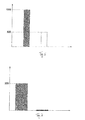
- FIG. 6 Figure 11 is a graph showing the mass inertia of the entire scroll compressor in kgmm 2 , with the prior art 1500 kgmm 2 left gray column representing the invention and the right white pillar the invention.
- the invention leads to an improvement of the mass inertia by a factor of 3. Since the displacement spiral 13 rotates in the off state, the inertia when connecting the scroll compressor is virtually zero. In contrast, the effective inertia when connecting a compressor of the prior art is up to 300 kgmm 2 .
- the resulting switch-on monument for the engine is in FIG.
Landscapes
- Engineering & Computer Science (AREA)
- Mechanical Engineering (AREA)
- General Engineering & Computer Science (AREA)
- Rotary Pumps (AREA)
- Applications Or Details Of Rotary Compressors (AREA)
- Air-Conditioning For Vehicles (AREA)
Abstract
Description
- Die Erfindung betrifft einen Scrollkompressor für eine CO2-Fahrzeugklimaanlage, sowie eine CO2-Fahrzeugklimaanlage mit einem solchen Scrollkompressor.
- Zur Klimatisierung von Kraftfahrzeugen kommen nichtbrennbare Kältemittel zum Einsatz, um bei einem Unfall die Explosionsgefahr im Fahrzeuginnenraum zu vermeiden. Die bisher verwendeten Kältemittel sind allerdings wegen ihres hohen Treibhauspotentials entweder bereits verboten oder werden zumindest als problematisch eingestuft. Als umweltverträgliches, nichtbrennbares Kältemittel kommt CO2 (R744) in Frage, das die bisherigen Kältemittel bereits teilweise ersetzt. CO2-Klimaanlagen arbeiten allerdings mit hohen Betriebsdrücken, die besondere Anforderungen an die Festigkeit und Dichtigkeit der Anlagekomponenten stellen. Der mit dem hohen Betriebsdruck verbundene Vorteil besteht darin, dass durch die höhere Dichte von CO2 ein geringerer Volumenstrom notwendig ist, um eine relativ hohe Kälteleistung zu erbringen.
- Ein Scrollkompressor für eine CO2-Fahrzeugklimaanlage mit den Merkmalen des Oberbegriffs des Anspruchs 1 ist aus
JP 2006/144635 A - So offenbart
US 6,273,692 B1 einen Scrollkompressor mit einem mechanischen Antrieb, der durch eine elektromagnetische Kupplung mit der Verdichteeinheit verbindbar ist. Solche Kupplungen weisen in der Regel eine schwere Stahlscheibe auf. Das Massenträgheitsmoment ist daher hoch, was sich entsprechend negativ auf den Verbrauch ausübt. Außerdem ist die Kupplung ein kostenintensives Bauteil.US 2002/0081224 A1 offenbart einen variablen Niederdruck-Scrollkompressor, der durch eine Radialbewegung einer der beiden Scrollspiralen zu- bzw. abschaltbar ist. Dabei wird die Exzentrizität zwischen den beiden Scrollspiralen aufgehoben, die so in radialer Richtung außer Eingriff gelangen. - Der Erfindung liegt die Aufgabe zugrunde, einen Scrollkompressor für eine CO2-Fahrzeugklimaanlage anzugeben, der einfach aufgebaut ist und eine Leistungsregelung ermöglicht. Der Erfindung liegt ferner die Aufgabe zugrunde, eine CO2-Fahrzeugklimaanlage mit einem solchen Scrollkompressor anzugeben.
- Erfindungsgemäß wird die Aufgabe durch einen Scrollkompressor für eine CO2-Fahrzeugklimaanlage mit den Merkmalen des Anspruchs 1 gelöst. Hinsichtlich der CO2-Fahrzeugklimaanlage wird die Aufgabe durch den Gegenstand des Anspruchs 15 gelöst.
- Die Erfindung hat mehrere Vorteile.
- Die Verwendung eines mechanischen Antriebs bzw. eines elektrischen Antriebs mit fester, d.h. zeitlich unveränderlicher Drehzahl ermöglicht eine im Vergleich zu drehzahlgeregelten Kompressoren kostengünstige Konstruktion. Die Leistungsregelung erfolgt durch die alternierende Bewegung der Gegenspirale relativ zur Verdrängerspirale in axialer Richtung. Dadurch wird temporär ein Druckausgleichsspalt zwischen der Gegenspirale und der Verdrängerspirale gebildet, so dass aus den radial weiter innen befindlichen Kammern des Kompressors verdichtetes Gas radial nach außen strömen kann. Dadurch wird der Druck im Scrollkompressor abgebaut. Die Verdrängerspirale läuft dabei weiter, so dass eine Kupplung zur Trennung des Kraftflusses zwischen Antrieb und Verdrängerspirale nicht erforderlich ist. Der erfindungsgemäße Scrollkompressor kann daher kupplungslos ausgeführt sein.
- Die Ausführung des Scrollkompressors als kupplungsloser Kompressor führt zu einer signifikanten Verringerung des Massenträgheitsmomentes. Da die Verdrängerspirale im lastfreien Zustand mitläuft, entfällt bei dem erfindungsgemäßen Scrollkompressor das Anfahrmoment. Außerdem wird die Belastung der drehenden Bauteile stark verringert und der Verbrauch gesenkt. Der erfindungsgemäße Scrollkompressor ist sehr laufruhig und geräuscharm.
- Die alternierende Bewegung der Gegenspirale wird durch eine axiale Lösekraft und eine dieser entgegengesetzte Schließkraft bewirkt. Erfindungsgemäß wird die axiale Lösekraft durch eine Feder aufgebracht, die zwischen der Verdrängerspirale und der Gegenspirale angeordnet ist. Die Lösekraft hebt die Gegenspirale von der Verdrängerspirale ab, so dass dazwischen der Druckausgleichsspalt entsteht und der Scrollkompressor abgeschaltet wird (Offenstellung). Für die axiale Schließkraft ist ein Kolben vorgesehen, der neben der Druckkammer an der Gegenspirale angreift. Die Schließkraft bringt die Gegenspirale in Anlage mit der Verdrängerspirale. Dabei wird der Druckausgleichsspalt geschlossen und der Scrollkompressor zugeschaltet (Schließstellung).
- Die erfindungsgemäße Anordnung der Feder und des Kolbens führt zu einem kompakten und robusten Aufbau des Scrollkompressors, der durch die alternierende Bewegung der Gegenspirale leistungsregelbar ist. Die Anordnung des Kolbens neben der Druckkammer führt dazu, dass die Druckkammer direkt mit dem Auslass für das verdichtete Gas, der in der Gegenspirale ausgebildet ist, verbunden werden kann. Die Druckkammer kann daher einbautenfrei ausgeführt sein, wodurch Probleme mit der Dichtigkeit im Bereich der Druckkammer vermieden werden.
- Im Vergleich zum Stand der Technik ermöglicht die Erfindung die Konstruktion von Scrollkompressoren für CO2-Fahrzeugklimaanlagen, deren Massenträgheitsmoment insgesamt um den Faktor 3 niedriger ist, als bei bekannten Scrollkompressoren. In absoluten Zahlen ermöglicht die Erfindung den Bau von Scrollkompressoren mit einem maximalen Massenträgheitsmoment von 500 kgmm2.
- Bevorzugte Ausführungen sind in den Unteransprüchen angegeben.
- Durch die bevorzugte Anordnung der Feder gegenüber der Druckkammer lässt sich eine besonders platzsparende Bauweise realisieren. Wenn zusätzlich der Kolben einen Ringkolben umfasst, der koaxial zur Gegenspirale verschieblich angeordnet ist, ergibt sich insgesamt ein robuster Aufbau für die Einleitung der Löse-und Schließkraft in die Gegenspirale. Der Ringkolben hat überdies den Vorteil, dass die Schließkraft über eine relativ große Fläche eingeleitet wird, wodurch der für die Schließkraft erforderliche Anpressdruck des Kolbens gleichmäßig verteilt wird.
- Die ohnehin bestehenden Druckunterschiede zwischen der Hochdruck- und der Saugseite des Scrollkompressors werden zur Betätigung des Kolbens genutzt, wenn der Kolben in einer Kolbenführung gelagert ist, die alternierend mit der Hochdruck- und der Saugseite des Scrollkompressors verbindbar ist. Um zu verhindern, dass beim Abheben der Gegenspirale von der Verdrängerspirale verdichtetes Gas von der Hochdruckseite zur Saugseite strömt und die Verdrängerspirale rückwärts dreht, ist der Druckkammer ein Rückschlagventil in Strömungsrichtung nachgeordnet. Bei einer weiteren bevorzugten Ausführung hat die Druckkammer eine Doppelfunktion und dient einerseits zur Dämpfung von Gaspulsationen und andererseits als Führung für die Gegenspirale. Dazu bildet eine auf der Hochdruckseite angeordnete Rückwand der Gegenspirale den Boden der Druckkammer, wobei die Gegenspirale einen Flansch aufweist, der an einer Innenwand der Druckkammer axial beweglich anliegt. Diese Doppelfunktion trägt zur kompakten Bauweise des Scrollkompressors bei.
- Die Dichtigkeit kann dadurch verbessert werden, wenn ein zur Saugseite abgeschlossener Aufnahmeraum für das Exzenterlager mit der Druckkammer fluidverbunden und eine Rückwand der Verdrängerspirale mit einem Anpressdruck beaufschlagbar ist.
- Es hat sich gezeigt, dass eine relativ geringe Exzentrizität für eine ausreichende Verdichtung des Kältemittels genügt. Dazu kann der Abstand zwischen dem Mittelpunkt der Gegenspirale und dem Mittelpunkt der Verdrängerspirale maximal 1,5 mm, insbesondere maximal 1,2 mm, insbesondere maximal 1,0 mm, insbesondere maximal 0,8 mm, insbesondere maximal 0,6 mm, insbesondere maximal 0,4 mm, insbesondere maximal 0,2 mm betragen. Die Untergrenze kann 0,1 mm betragen.. Vorzugsweise weist die Gegenspirale einen Windungswinkel von 660° bis 720°, insbesondere von 680° bis 700° auf, wodurch eine ausreichende Verdichtung des Kältemittels erzielt wird.
- Bei einer weiteren bevorzugten Ausführung ist vorgesehen, dass das Exzenterlager im Verdrängerraum zwischen der Verdrängerspirale und der Gegenspirale angeordnet ist und eine Lagerbuchse aufweist, die einstückig mit der Verdrängerspirale ausgebildet ist und deren Boden mit der Stirnseite der Windungen der Verdrängerspirale fluchtet. Somit ist die Lagerbuchse des Exzenterlagers in Richtung der Hochdruckseite vertieft angeordnet, wobei sich das Exzenterlager zumindest teilweise auf Höhe der Windungen der Gegenspirale befindet. Das Exzenterlager taucht also in die Gegenspirale ein. Das bei den bekannten Niederdruck-Scrollkompressoren zur Endverdichtung genutzte innerste Volumen zwischen der Verdrängerspirale und der Gegenspirale wird bei dieser Ausführung zumindest teilweise für die Ausbildung der Lagerbuchse und somit zur Aufnahme des Exzenterlagers genutzt. Dadurch werden etwaige Kippmomente verringert und die Laufruhe verbessert. Außerdem hat diese Ausführung den weiteren Vorteil, dass die vertieft angeordnete Lagerbuchse eine Auflagefläche für die Feder zwischen der Verdrängerspirale und der Gegenspirale bildet. Diese Ausgestaltung ist daher besonders vorteilhaft im Zusammenhang mit der Anordnung der Feder gegenüber der Druckkammer.
- Etwaige Kippmomente werden weiter verringert, wenn die Verdrängerspirale eine mittige Ausnehmung aufweist, in der zumindest teilweise ein Gegengewicht aufgenommen ist, das mit dem Exzenterlager verbunden ist. Vorzugsweise ist das Volumen der Druckkammer um den Faktor 5-7, insbesondere um den Faktor 6, größer als das Saugvolumen pro Umdrehung der Verdrängerspirale, wodurch Gaspulsationen wirksam verringert werden.
- Die Erfindung wird in weiteren Einzelheiten unter Bezug auf die beigefügten schematischen Zeichnungen anhand von Ausführungsbeispielen näher erläutert.
- In diesen zeigen
- Figur 1
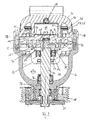
- einen Längsschnitt eines Scrollkompressors nach einem erfindungsgemäßen Ausführungsbeispiel in der Offenstellung;
- Figur 2
- einen weiteren Längsschnitt durch den Scrollkompressor gemäß
Figur 1 , der den Aufbau des Exzenterlagers verdeutlicht; - Figur 3
- eine Detailansicht des Scrollkompressors gemäß
Figur 1 im Bereich des Gehäusedeckels; - Figur 4
- eine Detailansicht wie in
Figur 3 , wobei sich der Kompressor in der Schließstellung befindet; - Figur 5
- einen Längsschnitt durch einen Kompressor nach einem weiteren erfindungsgemäßen Ausführungsbeispiel mit einem elektrischen Antrieb mit konstanter bzw. fester Drehzahl;
- Figur 6
- einen Vergleich der Massenträgheit des gesamten Kompressors in kgmm2 mit dem Stand der Technik;
- Figur 7
- einen Vergleich der wirksamen Massenträgheit beim Zuschalten des Kompressors in kgmm2 mit dem Stand der Technik und
- Figur 8
- ein Vergleichsdiagramm für das Einschaltmoment in Nm.
- Der nachfolgend im Detail beschriebene Scrollkompressor ist für den Einsatz in einer CO2-Fahrzeugklimaanlage konzipiert, die typischerweise einen Gaskühler, einen inneren Wärmetauscher, eine Drossel, einen Verdampfer und einen Verdichter umfasst. Solche Anlage sind für Maximaldrücke über 100 bar ausgelegt. Der Verdichter ist ein Scrollkompressor, der auch als Spiralverdichter bezeichnet wird. Wie in den
Figuren 1 und2 dargestellt, weist der Scrollkompressor einen mechanischen Antrieb 10 in der Form einer Riemenscheibe auf. Die Riemenscheibe ist im Gebrauch mit einem Elektromotor oder einem Verbrennungsmotor verbunden. - Der Scrollkompressor umfasst ferner ein Gehäuse 30 mit einem Gehäusedeckel 31, der die Hochdruckseite des Kompressors verschließt und mit dem Gehäuse 30 verschraubt ist. Im Gehäuse 30 ist eine Gehäusezwischenwand 32 angeordnet, die einen Saugraum 33 begrenzt. Im Gehäuseboden 34 ist eine Durchtrittsöffnung ausgebildet, durch die sich eine Antriebswelle 11 erstreckt. Das außerhalb des Gehäuses 30 angeordnete Wellenende ist drehfest mit einem Mitnehmer 35 verbunden, der in die am Gehäuse 30 drehbar gelagerte Riemenscheibe eingreift, so dass von der Riemenscheibe ein Drehmoment auf die Antriebswelle 11 übertragen werden kann. Die Antriebswelle 11 ist einerseits im Gehäuseboden 34 und andererseits in der Gehäusezwischenwand 32 drehbar gelagert. Die Abdichtung der Antriebswelle 11 gegen den Gehäuseboden 34 erfolgt durch eine erste Wellendichtung 36 und gegen die Gehäusezwischenwand 32 durch eine zweite Wellendichtung 37.
- Die Antriebswelle 11 überträgt das Drehmoment auf eine Verdichtereinheit, die wie folgt aufgebaut ist.
- Die Verdichtereinheit umfasst eine bewegliche Verdrängerspirale 13 und eine Gegenspirale 14. Die Verdrängerspirale 13 und die Gegenspirale 14 greifen ineinander ein. Die Gegenspirale 14 steht in Umfangsrichtung und in radialer Richtung fest. Die mit der Antriebswelle 11 gekoppelte bewegliche Verdrängerspirale 13 beschreibt eine kreisförmige Bahn, so dass in an sich bekannter Weise durch diese Bewegung mehrere Gastaschen oder Gaskammern erzeugt werden, die zwischen der Verdrängerspirale 13 und der Gegenspirale 14 radial nach innen wandern. Durch diese orbitierende Bewegung wird in die geöffnete äußere Gaskammer Kältemitteldampf angesaugt und mit der weiteren Spiralbewegung und der damit einhergehenden Verkleinerung der Gaskammer verdichtet. Der Kältemitteldampf wird von radial außen nach radial innen linear zunehmend verdichtet und im Zentrum der Gegenspirale 14 in eine Druckkammer 15 ausgestoßen.
- Für die orbitierende Bewegung der Verdrängerspirale 13 ist ein Exzenterlager 12 vorgesehen, das mit der Antriebswelle durch einen Exzenterstift 38 verbunden ist (s.
Figur 2 ). Das Exzenterlager 12 und die Verdrängerspirale 13 sind exzentrisch bezogen auf die Gegenspirale 14 angeordnet. Die Gaskammern sind durch Anlage der Verdrängerspirale 13 an der Gegenspirale 14 voneinander druckdicht getrennt. Der radiale Anpressdruck zwischen der Verdrängerspirale 13 und der Gegenspirale 14 wird durch die Exzentrizität eingestellt. - Eine Rotationsbewegung der Verdrängerspirale wird durch mehrere Führungsstifte 39 vermieden, die, wie in
Figur 2 dargestellt, in der Zwischenwand 32 befestigt sind. Die Führungsstifte 39 greifen in korrespondierende Führungsbohrungen 40 ein, die in der Verdrängerspirale 13 ausgebildet sind. Ein Gegengewicht 28 ist, vorzugsweise einstückig, mit dem Exzenterlager 12 verbunden, um die durch die orbitierende Bewegung der Verdrängerspirale 13 entstehende Unwucht zu kompensieren. - Der in
Figuren 1 ,2 dargestellte Scrollkompressor ist kupplungslos. Um trotzdem die Leistung des Kompressors verändern zu können, ist der Scrollkompressor zu-und abschaltbar (Digitalschaltung). Dazu ist vorgesehen, dass die Gegenspirale 14 in axialer Richtung, d. h. in einer Richtung parallel zur Antriebswelle 11 alternierend beweglich ist. Die Verdrängerspirale 13 steht in axialer Richtung fest. Damit kann die Gegenspirale 14 von der Verdrängerspirale 13 in axialer Richtung abgehoben werden, wie in denFiguren 1 bis 3 dargestellt. In dieser Offenstellung entsteht ein Druckausgleichsspalt 41 zwischen der Verdrängerspirale 13 und der Gegenspirale 14, der die in radialer Richtung voneinander getrennten Gaskammern zwischen der Verdrängerspirale 13 und der Gegenspirale 14 verbindet. Dies ist gut inFigur 3 zu sehen. Durch diesen Druckausgleichsspalt 41 strömt verdichtetes Gas aus den weiter innen angeordneten Kammern radial nach außen, wodurch ein Druckausgleich stattfindet. Die Leistung des Scrollkompressors wird dadurch auf 0 oder zumindest nahezu auf 0 gesenkt. - Die für die axiale Beweglichkeit der Gegenspirale 14 erforderliche Axialführung wird durch die Druckkammer 15 erfüllt, die außerdem Gaspulsationen dämpft. Die Druckkammer 15 hat daher eine Doppelfunktion:
- Sie ist der Gegenspirale in Strömungsrichtung nachgeordnet und steht mit dieser in Fluidverbindung durch den nicht dargestellten Auslass der Gegenspirale 14. Der Auslass ist nicht exakt im Mittelpunkt der Gegenspirale 14 angeordnet, sondern befindet sich außermittig im Bereich der innersten Kammer zwischen der Verdrängerspirale 13 und der Gegenspirale 14. Dadurch wird erreicht, dass der Auslass von der Lagerbuchse 26 des Exzenterlagers 12 nicht abgedeckt wird und der endverdichtete Dampf in die Druckkammer 15 ausgestoßen werden kann.
- Für die Axialführung der Gegenspirale 14 bildet die Druckkammer 15 am axialen Ende, das der Gegenspirale 14 zugewandt ist, eine innere Gleitfläche 42. Die Gleitfläche 42 ist bearbeitet und dichtet gegen die Gegenspirale 14 ab. Die Rückwand 21 der Gegenspirale 14 bildet den Boden der Druckkammer 15. Die Gegenspirale 14 schließt also direkt mit der Druckkammer 15 ab. Die Rückwand 21 weist ferner einen Flansch 22, insbesondere einen Ringflansch 22 auf, der an der Gleitfläche 42 der Druckkammer 15 anliegt. Der Flansch 22 dient als Axialführung der Gegenspirale 14 in der Druckkammer 15. Auf dem Außenumfang des Flansches 22 ist eine Nut mit einem Dichtmittel, beispielsweise einem Dichtring 43 ausgebildet. Die Druckkammer 15 wird durch eine Umfangswandung 44 begrenzt, die einen Anschlag 45 bildet und die axiale Bewegung der Gegenspirale 14 begrenzt.
- Die Druckkammer 15 ist im Gehäusedeckel 31 vorgesehen. Dadurch wird die Montage der axialbeweglichen Gegenspirale 14 vereinfacht. Außerdem weist sie einen rotationssymmetrischen Querschnitt auf.
- Für die alternierende Bewegung der Gegenspirale 14 zwischen der Offenstellung (
Figur 3 ) und der Schließstellung (Figur 4 ) sind entgegengesetzte Axialkräfte erforderlich. Die Axialkraft, die die Gegenspirale 14 in die Offenstellung (Figur 3 ) bewegt und somit die Gegenspirale 14 von der Verdrängerspirale 13 löst (axiale Lösekraft), wird durch eine Feder 16 erzeugt, die zwischen der Verdrängerspirale 13 und der Gegenspirale 14 angeordnet ist. Die Feder 16 kann beispielsweise als Tellerfeder ausgebildet sein. Die Feder 16 ist in der Schließstellung gemäßFigur 4 vorgespannt und drängt die Gegenspirale 14 und die Verdrängerspirale 13 auseinander. - Wie in
Figuren 3, 4 gut zu erkennen, ist die Feder 16 gegenüber der Druckkammer 15 angeordnet. Dazu ist in der Gegenspirale 14 eine zentrale Ausnehmung 46 vorgesehen, in der die Feder 16 angeordnet ist. Die Feder 16 stützt sich auf der Verdrängerspirale 13 ab. Dazu ist vorgesehen, dass die Lagerbuchse 26 für das Exzenterlager 12 in der Verdrängerspirale 13 vertieft angeordnet ist. Die Lagerbuchse 26 taucht dabei in die Gegenspirale 14 ein und ragt in die Gegenspirale 14 hinein. Der Boden der Lagerbuchse 26, auf dem sich die Feder 16 abstützt, befindet sich auf derselben Höhe, wie die Innenkanten der Windungen der Verdrängerspirale 13. Dies ist gut inFigur 3 zu erkennen (Offenstellung). In der Schließstellung gemäßFigur 4 liegt deshalb der Boden der Lagerbuchse 26 an der Gegenspirale 14 an und dichtet die innerste Gaskammer zwischen der Verdrängerspirale 13 und der Gegenspirale 14 ab. - Um die Gegenspirale 14 aus der in
Figur 3 dargestellten Offenstellung in die inFigur 4 gezeigte Schließstellung zu überführen, ist ein Kolben 17, insbesondere ein Ringkolben 17 vorgesehen, der koaxial zur Längsachse der Gegenspirale 14 verschiebbar ist. Anstelle des Ringkolbens 17 können auch mehrere auf dem Umfang der Gegenspirale 14 angeordnete zylindrische Kolben vorgesehen sein. Der Ringkolben 17 greift an der Rückwand 21 der Gegenspirale 14 an und beaufschlagt diese mit einer Schließkraft, die gegen die Federkraft der Feder 16 arbeitet. - Der Kolben 17 greift, wie in den
Figuren 1 bis 4 zu erkennen, neben der Druckkammer 15 an der Gegenspirale 14 an. Der Kolben 17 ist somit außerhalb der Druckkammer 15 bzw. allgemein außermittig angeordnet. Für die Fluidverbindung zwischen der Gegenspirale 14 und der Druckkammer 15 kann deshalb eine einfache Auslassöffnung in der Gegenspirale 14 ausgebildet sein (nicht dargestellt). - Der Ringkolben 17 weist einen Anpressring 47 auf, der mit einem Boden 48 des Kolbens verbunden ist. Der Kolbenboden 48 ist in einer Axialführung 18 axial verschieblich und druckdicht gelagert. Die Axialführung 18 ist als Ringkammer ausgebildet. Für die Betätigung des Ringkolbens 17 ist die Ringkammer mit einem Versorgungsanschluss 20c verbunden. Wie in
Figur 1 dargestellt, ist der Versorgungsanschluss 20c mit einem 2/3-Wegeventil verbunden, das wiederum mit einem Hochdruckanschluss 20a und einem Saugdruckanschluss 20b verbunden ist, so dass die Ringkammer alternierend mit Hochdruck oder Saugdruck beaufschlagbar ist. Dadurch kann die Gegenspirale 14 alternierend zwischen der Offenstellung oder der Schließstellung hin und her bewegt werden. Dabei arbeitet der Ringkolben 17 im Wesentlichen nur gegen die Federkraft der Feder 16, weil der in der Druckkammer 15 herrschende und auf die Gegenspirale 14 wirkende Druck zumindest teilweise durch den zwischen der Gegenspirale 14 und der Verdrängerspirale 13 wirkenden Druck bei der Verdichtung kompensiert wird. Außerdem sind nur relativ kleine Hubwege erforderlich, um den Druckausgleichsspalt 41 einzustellen. Beispielsweise reichen Hubwege von ca. 0,3 bis 0,7 mm, insbesondere ein Hubweg von ca. 0,5 mm aus. - Die Leistungsregelung erfolgt bei dem Scrollkompressor durch Ein- bzw. Ausschaltung der Verdichterleistung, konkret durch die Änderung der Frequenz der zyklischen bzw. alternierenden Bewegung der Gegenspirale 14.
- Das in der Druckkammer 15 gesammelte verdichtete Gas strömt durch einen Auslass 49 aus der Druckkammer 15 in einen Ölabscheider 29, der vorliegend als Zyklonabscheider ausgebildet ist. Das verdichtete Gas strömt durch den Ölabscheider 29 und ein Rückschlagventil 19 in den Kreislauf der Klimaanlage. Das Rückschlagventil 19, das ein Zurückströmen des verdichteten Gases in den ausgeschalteten Scrollkompressor verhindert, ist beispielsweise auf Druckdifferenzen von 0,5 bis 1 bar ausgelegt.
- Die Abdichtung der Verdrängerspirale 13 gegen die Gegenspirale 14 in axialer Richtung wird dadurch unterstützt, dass eine Rückwand 25 der Verdrängerspirale mit Hochdruck beaufschlagt wird. Dazu ist ein Aufnahmeraum 24, auch als Backpressure-Raum bezeichnet (
Figur 1 ), in dem ein Teil des Gegengewichts 28 und das Exzenterlager 12 angeordnet sind, mit der Hochdruckseite fluidverbunden. Der Aufnahmeraum 24 wird durch die Rückwand 25 der Verdichterspirale 13 und die Gehäusezwischenwand 32 begrenzt. - Der Aufnahmeraum 24 ist durch die eingangs beschriebene zweite Wellendichtung 37 vom Saugraum 33 fluiddicht getrennt. Ein Dicht- und Gleitring 52 ist zwischen der Verdrängerspirale 13 und der Gehäusezwischenwand 32 angeordnet und dichtet den Aufnahmeraum 24 gegen die Hochdruckseite ab. Der Dicht- und Gleitring 52 sitzt in einer Ringnut in der Gehäusezwischenwand 32. Zwischen der Gehäusezwischenwand 32 und der Verdrängerspirale 13 ist ein Spalt ausgebildet (nicht dargestellt). Die Verdrängerspirale 13 stützt sich deshalb in axialer Richtung nicht direkt auf der Gehäusezwischenwand 32 sondern auf dem Dicht- und Gleitring 52 ab und gleitet auf diesem. Der Dicht- und Gleitring 52 steht dazu aus der Ringnut vor und dichtet den Spalt ab. Der Spalt kann ca. 0,2 mm bis 0,5 mm breit sein.
- Für den Anschluss an die Hochdruckseite verbindet eine Leitung 50 den Ölabscheider 29 mit dem Aufnahmeraum 24. Diese erstreckt sich durch den Gehäusedeckel 31, die Gegenspirale 14 und die Zwischenwand 32. Zwischen dem Ölabscheider 29 und dem Aufnahmeraum 24, konkret zwischen der Gegenspirale 14 und dem Gehäusedeckel 31, ist ein Druckminderer 53 angeordnet, der dafür sorgt, dass zwischen der Hochdruckseite und dem Aufnahmeraum 24 eine Druckdifferenz von ca. 10%-20% herrscht. Dadurch wird erreicht, dass in der Schließstellung der axiale Anpressdruck zwischen der Verdrängerspirale 13 und der Gegenspirale 14 und damit die axiale Dichtigkeit erhöht wird.
- In thermischer Hinsicht ist der in
Figur 1 dargestellte Scrollkompressor dahingehend optimiert, dass eine unerwünschte Aufheizung des Kältemitteldampfes auf der Saugseite vermindert wird. Dazu ist die Druckkammer 15 gekapselt (s.Figur 4 ). Im Übrigen ist die Druckkammer 15 einbautenfrei. Beispielsweise kann die Druckkammer eine Innenhülle 51, insbesondere aus Edelstahl oder nichtrostendem Stahl aufweisen. Die Innenhülle 51 hat einen niedrigere Wärmeleitfähigkeit als Aluminium. Zusätzlich verringert die thermische Isolierung des Ölabscheiders 29 die Aufheizung des Kältemitteldampfes auf der Saugseite. Auch hier erfolgt die thermische Isolierung durch eine Kapselung, beispielsweise durch eine Innenhülle aus Edelstahl oder nichtrostendem Stahl, die den Zyklonabscheider umgibt. Ferner ist der Druckminderer 53 durch eine Kapselung mit einer Innenhülle aus Edelstahl oder nichtrostendem Stahl isoliert. - Damit ist es möglich, den Gehäusedeckel 31 beispielsweise aus Aluminium zu fertigen, ohne dass eine übermäßige Wärmeübertragung von der Hochdruckseite auf die Saugseite zu befürchten ist.
- Der einzige Unterschied zwischen dem Scrollkompressor gemäß
Figur 5 und dem Scrollkompressor gemäßFigur 1 besteht darin, dass anstelle des mechanischen Antriebes ein elektrischer Antrieb mit konstanter, d.h. zeitlich unveränderlicher Drehzahl verwendet wird. Im Übrigen wird auf die Ausführungen im Zusammenhang mit dem mechanisch angetriebenen Scrollkompressor verwiesen. - Die Vorteile des erfindungsgemäßen Scrollkompressors sind in den
Figuren 6 bis 8 dargestellt.Figur 6 zeigt ein Diagramm, das die Massenträgheit des gesamten Scrollkompressors in kgmm2 darstellt, wobei die linke graue Säule mit 1500 kgmm2 den Stand der Technik und die rechte weiße Säule die Erfindung wiedergibt. Die Erfindung führt zu einer Verbesserung der Massenträgheit um den Faktor 3. Da die Verdrängerspirale 13 im ausgeschalteten Zustand mitdreht, ist die Massenträgheit beim Zuschalten des Scrollkompressors praktisch null. Im Gegensatz dazu beträgt die wirksame Massenträgheit beim Zuschalten eines Kompressors aus dem Stand der Technik bis zu 300 kgmm2. Das daraus resultierende Einschaltmonument für den Motor ist inFigur 8 gezeigt, wobei das linke Diagramm die Drehmomentspitze bei einem im Stand der Technik bekannten Motor und das rechte Diagramm den Drehmomentverlauf beim Einschalten eines Scrollkompressors nach der Erfindung zeigt.Bezugszeichenliste 10 Antrieb 11 Antriebswelle 12 Exzenterlage 13 Verdrängerspirale 14 Gegenspirale 15 Druckkammer 16 Feder 17 Kolben / Ringkolben 18 Kolbenführung 19 Rückschlagventil 20a Hochdruckanschluss 20b Saugdruckanschluss 20c Versorgungsanschluss 21 Rückwand Gegenspirale 22 Flansch 23 Innenwand 24 Aufnahmeraum 25 Rückwand Verdrängerspirale 26 Lagerbuchse 27 Ausnehmung 28 Gegengewicht 29 Ölabscheider 30 Gewicht 31 Gehäusedeckel 32 Gehäusezwischenwand 33 Saugraum 34 Gehäuseboden 35 Mitnehmer 36 erste Wellendichtung 37 zweite Wellendichtung 38 Exzenterstift 39 Führungsstifte 40 Führungsbohrungen 41 Druckausgleichsspalt 42 Gleitfläche 43 Dichtring 44 Wandung 45 Anschlag 46 zentrale Ausnehmung 47 Anpressring 48 Kolbenboden 49 Auslass 50 Leitung 51 Innenhülle 52 Gleit- und Dichtring 53 Druckminderer
Claims (15)
- Scrollkompressor für eine CO2-Fahrzeugklimaanlage mit einem Antrieb (10), der durch eine Antriebswelle (11) mit einem Exzenterlager (12) verbunden ist, und einer beweglichen Verdrängerspirale (13), die mit dem Exzenterlager (12) drehbar verbunden ist und in eine Gegenspirale (14) derart eingreift, dass zwischen der Verdrängerspirale (13) und der Gegenspirale (14) radial nach innen wandernde Kammern gebildet werden, um das Kältemittel zu verdichten und in eine Druckkammer (15) auszustoßen,
dadurch gekennzeichnet, dass
der Antrieb (10) ein mechanischer Antrieb oder ein elektrischer Antrieb mit fester Drehzahl ist und die Gegenspirale (14) relativ zur Verdrängerspirale (13) in axialer Richtung alternierend beweglich ist, wobei zwischen der Gegenspirale (14) und der Verdrängerspirale (13) wenigstens eine Feder (16) angeordnet ist, um die Gegenspirale (14) mit einer axialen Lösekraft zu beaufschlagen, und wenigstens ein Kolben (17) neben der Druckkammer (15) an der Gegenspirale (14) angreift, um diese mit einer axialen Schließkraft zu beaufschlagen. - Scrollkompressor nach Anspruch 1,
dadurch gekennzeichnet, dass
die Feder (16) gegenüber der Druckkammer (15) angeordnet ist. - Scrollkompressor nach Anspruch 1 oder 2,
dadurch gekennzeichnet, dass
der Kolben (17) einen Ringkolben umfasst, der koaxial zur Gegenspirale (14) verschieblich angeordnet ist. - Scrollkompressor nach einem der Ansprüche 1 bis 3,
dadurch gekennzeichnet, dass
der Kolben (17) in einer Kolbenführung (18) gelagert ist, die alternierend mit einer Hochdruckseite und einer Saugseite des Scrollkompressors verbindbar ist. - Scrollkompressor nach einem der Ansprüche 1 bis 4,
dadurch gekennzeichnet, dass
der Druckkammer (15) ein Rückschlagventil (19) in Strömungsrichtung nachgeordnet ist. - Scrollkompressor nach Anspruch 5,
dadurch gekennzeichnet, dass
der Anschluss (20) für die Verbindung der Kolbenführung (18) mit der Hochdruckseite zwischen der Druckkammer (15) und dem Rückschlagventil (19) angeordnet ist. - Scrollkompressor nach einem der Ansprüche 1 bis 6,
dadurch gekennzeichnet, dass
eine auf der Hochdruckseite angeordnete Rückwand (21) der Gegenspirale (14) den Boden der Druckkammer (15) bildet und einen Flansch (22) aufweist, der an einer Innenwand (23) der Druckkammer (15) axial beweglich anliegt. - Scrollkompressor nach einem der Ansprüche 1 bis 7,
dadurch gekennzeichnet, dass
ein zur Saugseite abgeschlossener Aufnahmeraum (24) für das Exzenterlager (12) mit der Druckkammer (15) fluidverbunden ist und eine Rückwand (25) der Verdrängerspirale (13) mit einem Anpressdruck beaufschlagbar ist. - Scrollkompressor nach einem der Ansprüche 1 bis 8,
dadurch gekennzeichnet, dass
der Abstand zwischen dem Mittelpunkt der Gegenspirale (14) und dem Mittelpunkt der Verdrängerspirale (13) maximal 1,5 mm, insbesondere maximal 1,2 mm, insbesondere maximal 1,0 mm, insbesondere maximal 0,8 mm, insbesondere maximal 0,6 mm, insbesondere maximal 0,4 mm, insbesondere maximal 0,2 mm beträgt. - Scrollkompressor nach einem der Ansprüche 1 bis 9,
dadurch gekennzeichnet, dass
die Gegenspirale (14) einen Windungswinkel von 660° bis 720°, insbesondere von 680° bis 700° aufweist. - Scrollkompressor nach einem der Ansprüche 1 bis 10,
dadurch gekennzeichnet, dass
das Massenträgheitsmoment des Scrollkompressors maximal 500 kgmm2 beträgt. - Scrollkompressor nach einem der Ansprüche 1 bis 11,
dadurch gekennzeichnet, dass
das Exzenterlager (12) im Verdrängerraum zwischen der Verdrängerspirale (13) und der Gegenspirale (14) angeordnet ist und eine Lagerbuchse (26) aufweist, die einstückig mit der Verdrängerspirale (13) ausgebildet ist und deren Boden (54) mit der Stirnseite der Windungen der Verdrängerspirale (13) fluchtet. - Scrollkompressor nach einem der Ansprüche 1 bis 12,
dadurch gekennzeichnet, dass
die Verdrängerspirale (13) eine mittige Ausnehmung (27) aufweist, in der zumindest teilweise ein Gegengewicht (28) aufgenommen ist, das mit dem Exzenterlager (12) verbunden ist. - Scrollkompressor nach einem der Ansprüche 1 bis 13,
dadurch gekennzeichnet, dass
das Volumen der Druckkammer (15) um den Faktor 5-7, insbesondere um den Faktor 6, größer als das Saugvolumen pro Umdrehung der Verdrängerspirale (13) ist und/oder die Druckkammer (15) thermisch isoliert ist. - Fahrzeugklimaanlage, die CO2 als Kältemittel enthält, mit einem Scrollkompressor nach Anspruch 1.
Priority Applications (4)
| Application Number | Priority Date | Filing Date | Title |
|---|---|---|---|
| EP13168737.8A EP2806165B1 (de) | 2013-05-22 | 2013-05-22 | Scrollkompressor und CO2-Fahrzeugklimaanlage mit einem Scrollkompressor |
| US14/282,540 US9291165B2 (en) | 2013-05-22 | 2014-05-20 | Scroll-type compressor and CO2 vehicle air conditioning system having a scroll-type compressor |
| JP2014104949A JP6425418B2 (ja) | 2013-05-22 | 2014-05-21 | スクロール型圧縮機およびスクロール型圧縮機を有するco2車両空調システム |
| CN201410216842.0A CN104179681B (zh) | 2013-05-22 | 2014-05-21 | 涡旋式压缩机以及具有涡旋式压缩机的co2车辆空调系统 |
Applications Claiming Priority (1)
| Application Number | Priority Date | Filing Date | Title |
|---|---|---|---|
| EP13168737.8A EP2806165B1 (de) | 2013-05-22 | 2013-05-22 | Scrollkompressor und CO2-Fahrzeugklimaanlage mit einem Scrollkompressor |
Publications (2)
| Publication Number | Publication Date |
|---|---|
| EP2806165A1 true EP2806165A1 (de) | 2014-11-26 |
| EP2806165B1 EP2806165B1 (de) | 2015-09-09 |
Family
ID=48520717
Family Applications (1)
| Application Number | Title | Priority Date | Filing Date |
|---|---|---|---|
| EP13168737.8A Active EP2806165B1 (de) | 2013-05-22 | 2013-05-22 | Scrollkompressor und CO2-Fahrzeugklimaanlage mit einem Scrollkompressor |
Country Status (4)
| Country | Link |
|---|---|
| US (1) | US9291165B2 (de) |
| EP (1) | EP2806165B1 (de) |
| JP (1) | JP6425418B2 (de) |
| CN (1) | CN104179681B (de) |
Cited By (1)
| Publication number | Priority date | Publication date | Assignee | Title |
|---|---|---|---|---|
| WO2017182516A1 (de) * | 2016-04-19 | 2017-10-26 | OET GmbH | Separatorvorrichtung zum abscheiden eines fluids, insbesondere eines schmierstoffs aus einem kühlmittelfluid |
Families Citing this family (6)
| Publication number | Priority date | Publication date | Assignee | Title |
|---|---|---|---|---|
| CN105402124B (zh) * | 2015-11-25 | 2018-10-23 | 珠海格力节能环保制冷技术研究中心有限公司 | 一种多级压缩机及空调系统 |
| DE102016113057B4 (de) * | 2016-07-15 | 2019-05-23 | Hanon Systems | Vorrichtung zum Verdichten eines gasförmigen Fluids mit einer Anordnung zum Separieren eines Steuermassenstroms sowie Verfahren zum Separieren des Steuermassenstroms |
| DE102017105175B3 (de) * | 2017-03-10 | 2018-08-23 | OET GmbH | Verdrängermaschine nach dem Spiralprinzip, Verfahren zum Betreiben einer Verdrängermaschine, Verdrängerspirale, Fahrzeugklimaanlage und Fahrzeug |
| US11739754B2 (en) * | 2018-08-24 | 2023-08-29 | Brose Fahrzeugtelle SE & Co. Kommanditgesellschaft | Compressor module having oil separator and electric-powered refrigerant compressor having the same |
| WO2021040360A1 (en) * | 2019-08-27 | 2021-03-04 | Samsung Electronics Co., Ltd. | Scroll compressor |
| CN115450908A (zh) * | 2022-09-21 | 2022-12-09 | 珠海格力电器股份有限公司 | 静盘组件、涡旋压缩机、新能源车 |
Citations (5)
| Publication number | Priority date | Publication date | Assignee | Title |
|---|---|---|---|---|
| JPS6263189A (ja) * | 1985-09-17 | 1987-03-19 | Nippon Soken Inc | スクロ−ル型圧縮機 |
| EP1087142A2 (de) * | 1999-09-21 | 2001-03-28 | Copeland Corporation | Spiralkompressor mit Kapazitätsregelung |
| US6273692B1 (en) | 1999-06-29 | 2001-08-14 | Sanden Corporation | Scroll-type compressor |
| US20020081224A1 (en) | 2000-12-22 | 2002-06-27 | Motohiko Ueda | Scroll-type compressor |
| JP2006144635A (ja) | 2004-11-18 | 2006-06-08 | Denso Corp | スクロール型圧縮機 |
Family Cites Families (25)
| Publication number | Priority date | Publication date | Assignee | Title |
|---|---|---|---|---|
| FR1482910A (fr) * | 1966-03-23 | 1967-06-02 | Pompe volumétrique | |
| US3817664A (en) * | 1972-12-11 | 1974-06-18 | J Bennett | Rotary fluid pump or motor with intermeshed spiral walls |
| US3874827A (en) * | 1973-10-23 | 1975-04-01 | Niels O Young | Positive displacement scroll apparatus with axially radially compliant scroll member |
| JPS581278B2 (ja) * | 1980-04-05 | 1983-01-10 | サンデン株式会社 | スクロ−ル型圧縮機 |
| US4610610A (en) * | 1984-08-16 | 1986-09-09 | Sundstrand Corporation | Unloading of scroll compressors |
| US4927339A (en) * | 1988-10-14 | 1990-05-22 | American Standard Inc. | Rotating scroll apparatus with axially biased scroll members |
| US5199280A (en) * | 1991-11-25 | 1993-04-06 | American Standard Inc. | Co-rotational scroll compressor supercharger device |
| JP3170111B2 (ja) | 1993-09-24 | 2001-05-28 | 株式会社日立製作所 | スクロール圧縮機 |
| US6047557A (en) * | 1995-06-07 | 2000-04-11 | Copeland Corporation | Adaptive control for a refrigeration system using pulse width modulated duty cycle scroll compressor |
| US5741120A (en) * | 1995-06-07 | 1998-04-21 | Copeland Corporation | Capacity modulated scroll machine |
| JP2002161875A (ja) * | 2000-11-27 | 2002-06-07 | Matsushita Electric Works Ltd | スクロールポンプ |
| JP2003227476A (ja) | 2002-02-05 | 2003-08-15 | Matsushita Electric Ind Co Ltd | 空気供給装置 |
| US6758659B2 (en) | 2002-04-11 | 2004-07-06 | Shimao Ni | Scroll type fluid displacement apparatus with fully compliant floating scrolls |
| US7265080B2 (en) | 2002-06-12 | 2007-09-04 | Nsk Ltd. | Rolling bearing, rolling bearing for fuel cell, compressor for fuel cell system and fuel cell system |
| CN2589697Y (zh) * | 2002-12-30 | 2003-12-03 | 财团法人工业技术研究院 | 涡卷式压缩机的负载调节装置 |
| JP2005023817A (ja) | 2003-07-01 | 2005-01-27 | Matsushita Electric Ind Co Ltd | スクロール圧縮機およびスクロールラップの加工方法 |
| CN2714847Y (zh) * | 2004-04-27 | 2005-08-03 | 瑞智精密股份有限公司 | 涡卷压缩机的背压机构 |
| JP2006200488A (ja) * | 2005-01-21 | 2006-08-03 | Sanden Corp | スクロール型圧縮機 |
| CN101395376B (zh) | 2006-03-03 | 2011-04-06 | 大金工业株式会社 | 压缩机及其制造方法 |
| JP2008121490A (ja) * | 2006-11-10 | 2008-05-29 | Daikin Ind Ltd | 回転式圧縮機 |
| US7771178B2 (en) * | 2006-12-22 | 2010-08-10 | Emerson Climate Technologies, Inc. | Vapor injection system for a scroll compressor |
| DE102008013784B4 (de) | 2007-03-15 | 2017-03-23 | Denso Corporation | Kompressor |
| US7611344B2 (en) | 2007-10-15 | 2009-11-03 | Scroll Laboratories, Inc. | Sealing tabs on orbiting scroll |
| WO2012144067A1 (ja) * | 2011-04-22 | 2012-10-26 | 株式会社日立製作所 | スクロール圧縮機 |
| JP2012237251A (ja) * | 2011-05-12 | 2012-12-06 | Mitsubishi Heavy Ind Ltd | スクロール型流体機械 |
-
2013
- 2013-05-22 EP EP13168737.8A patent/EP2806165B1/de active Active
-
2014
- 2014-05-20 US US14/282,540 patent/US9291165B2/en not_active Expired - Fee Related
- 2014-05-21 JP JP2014104949A patent/JP6425418B2/ja not_active Expired - Fee Related
- 2014-05-21 CN CN201410216842.0A patent/CN104179681B/zh not_active Expired - Fee Related
Patent Citations (5)
| Publication number | Priority date | Publication date | Assignee | Title |
|---|---|---|---|---|
| JPS6263189A (ja) * | 1985-09-17 | 1987-03-19 | Nippon Soken Inc | スクロ−ル型圧縮機 |
| US6273692B1 (en) | 1999-06-29 | 2001-08-14 | Sanden Corporation | Scroll-type compressor |
| EP1087142A2 (de) * | 1999-09-21 | 2001-03-28 | Copeland Corporation | Spiralkompressor mit Kapazitätsregelung |
| US20020081224A1 (en) | 2000-12-22 | 2002-06-27 | Motohiko Ueda | Scroll-type compressor |
| JP2006144635A (ja) | 2004-11-18 | 2006-06-08 | Denso Corp | スクロール型圧縮機 |
Cited By (4)
| Publication number | Priority date | Publication date | Assignee | Title |
|---|---|---|---|---|
| WO2017182516A1 (de) * | 2016-04-19 | 2017-10-26 | OET GmbH | Separatorvorrichtung zum abscheiden eines fluids, insbesondere eines schmierstoffs aus einem kühlmittelfluid |
| CN109072920A (zh) * | 2016-04-19 | 2018-12-21 | 欧伊特股份有限公司 | 从冷却剂流体中分离流体,特别是润滑剂的分离器装置 |
| CN109072920B (zh) * | 2016-04-19 | 2020-05-22 | 欧伊特股份有限公司 | 从冷却剂流体中分离流体,特别是润滑剂的分离器装置 |
| US10935027B2 (en) | 2016-04-19 | 2021-03-02 | OET GmbH | Separator device for separating a fluid, in particular a lubricant, from a coolant |
Also Published As
| Publication number | Publication date |
|---|---|
| JP2014228003A (ja) | 2014-12-08 |
| JP6425418B2 (ja) | 2018-11-21 |
| EP2806165B1 (de) | 2015-09-09 |
| US9291165B2 (en) | 2016-03-22 |
| US20140348682A1 (en) | 2014-11-27 |
| CN104179681B (zh) | 2018-03-16 |
| CN104179681A (zh) | 2014-12-03 |
Similar Documents
| Publication | Publication Date | Title |
|---|---|---|
| EP2806165B1 (de) | Scrollkompressor und CO2-Fahrzeugklimaanlage mit einem Scrollkompressor | |
| EP2806164B1 (de) | Scrollkompressor und CO2-Fahrzeugklimaanlage mit einem Scrollkompressor | |
| DE69928055T2 (de) | Liefermengenregelung eines Verdichters | |
| EP3545195B1 (de) | Verdrängermaschine nach dem spiralprinzip, verfahren zum betreiben einer verdrängermaschine, verdrängerspirale, fahrzeugklimaanlage und fahrzeug | |
| EP2584200B1 (de) | Gaseinlassventil für einen kompressor, kompressor mit einem derartigen gaseinlassventil sowie verfahren zum betreiben eines kompressors mit einem derartigen gaseinlassventil | |
| DE602004009026T2 (de) | Spiralverdichter | |
| DE19650108A1 (de) | Taumelscheiben-Kompressor | |
| DE102016122028A1 (de) | Taumelscheibenkompressor mit variabler Fördermenge | |
| DE3923304C2 (de) | ||
| DE4200305A1 (de) | Regelbare fluegelzellenpumpe in kompakter bauweise | |
| DE69408713T2 (de) | Rotationsgaskompressor | |
| DE19722688C2 (de) | Kompressor | |
| EP1240433B1 (de) | Trockenverdichtende Vakuumpumpe mit Gasballasteinrichtung | |
| EP1297256B1 (de) | Sicherheitseinrichtung für klimakompressor | |
| DE10225416B4 (de) | Drehvorrichtung | |
| DE102016203587A1 (de) | Taumelscheibenverdichter mit veränderlicher Verdrängung | |
| DE102016217358A1 (de) | Scrollverdichter | |
| DE102017102645B4 (de) | Kältemittel-Scrollverdichter für die Verwendung innerhalb einer Wärmepumpe | |
| DE102019208680A1 (de) | Verdrängermaschine nach dem Spiralprinzip, insbesondere Scrollverdichter für eine Fahrzeugklimaanlage | |
| DE19919141A1 (de) | Elektromotorisch angetriebener Kompressor | |
| DE102020210453B4 (de) | Scrollverdichter eines elektrischen Kältemittelantriebs | |
| EP1899605B1 (de) | Steuerungsventil für einen kältemittelverdichter und kältemittelverdichter | |
| DE102020203491B4 (de) | Scroll-Verdichter | |
| EP1662141B1 (de) | Axialkolbenverdichter | |
| EP2499366A1 (de) | Klimakompressor für ein fahrzeug, fahrzeug |
Legal Events
| Date | Code | Title | Description |
|---|---|---|---|
| PUAI | Public reference made under article 153(3) epc to a published international application that has entered the european phase |
Free format text: ORIGINAL CODE: 0009012 |
|
| 17P | Request for examination filed |
Effective date: 20131126 |
|
| AK | Designated contracting states |
Kind code of ref document: A1 Designated state(s): AL AT BE BG CH CY CZ DE DK EE ES FI FR GB GR HR HU IE IS IT LI LT LU LV MC MK MT NL NO PL PT RO RS SE SI SK SM TR |
|
| AX | Request for extension of the european patent |
Extension state: BA ME |
|
| RIC1 | Information provided on ipc code assigned before grant |
Ipc: F04C 18/02 20060101AFI20150210BHEP |
|
| GRAP | Despatch of communication of intention to grant a patent |
Free format text: ORIGINAL CODE: EPIDOSNIGR1 |
|
| INTG | Intention to grant announced |
Effective date: 20150320 |
|
| GRAS | Grant fee paid |
Free format text: ORIGINAL CODE: EPIDOSNIGR3 |
|
| GRAA | (expected) grant |
Free format text: ORIGINAL CODE: 0009210 |
|
| AK | Designated contracting states |
Kind code of ref document: B1 Designated state(s): AL AT BE BG CH CY CZ DE DK EE ES FI FR GB GR HR HU IE IS IT LI LT LU LV MC MK MT NL NO PL PT RO RS SE SI SK SM TR |
|
| REG | Reference to a national code |
Ref country code: GB Ref legal event code: FG4D Free format text: NOT ENGLISH |
|
| REG | Reference to a national code |
Ref country code: AT Ref legal event code: REF Ref document number: 748362 Country of ref document: AT Kind code of ref document: T Effective date: 20150915 Ref country code: CH Ref legal event code: EP |
|
| REG | Reference to a national code |
Ref country code: IE Ref legal event code: FG4D Free format text: LANGUAGE OF EP DOCUMENT: GERMAN |
|
| REG | Reference to a national code |
Ref country code: DE Ref legal event code: R096 Ref document number: 502013001119 Country of ref document: DE |
|
| REG | Reference to a national code |
Ref country code: NL Ref legal event code: MP Effective date: 20150909 |
|
| PG25 | Lapsed in a contracting state [announced via postgrant information from national office to epo] |
Ref country code: LT Free format text: LAPSE BECAUSE OF FAILURE TO SUBMIT A TRANSLATION OF THE DESCRIPTION OR TO PAY THE FEE WITHIN THE PRESCRIBED TIME-LIMIT Effective date: 20150909 Ref country code: GR Free format text: LAPSE BECAUSE OF FAILURE TO SUBMIT A TRANSLATION OF THE DESCRIPTION OR TO PAY THE FEE WITHIN THE PRESCRIBED TIME-LIMIT Effective date: 20151210 Ref country code: LV Free format text: LAPSE BECAUSE OF FAILURE TO SUBMIT A TRANSLATION OF THE DESCRIPTION OR TO PAY THE FEE WITHIN THE PRESCRIBED TIME-LIMIT Effective date: 20150909 Ref country code: FI Free format text: LAPSE BECAUSE OF FAILURE TO SUBMIT A TRANSLATION OF THE DESCRIPTION OR TO PAY THE FEE WITHIN THE PRESCRIBED TIME-LIMIT Effective date: 20150909 Ref country code: NO Free format text: LAPSE BECAUSE OF FAILURE TO SUBMIT A TRANSLATION OF THE DESCRIPTION OR TO PAY THE FEE WITHIN THE PRESCRIBED TIME-LIMIT Effective date: 20151209 |
|
| REG | Reference to a national code |
Ref country code: LT Ref legal event code: MG4D |
|
| PG25 | Lapsed in a contracting state [announced via postgrant information from national office to epo] |
Ref country code: HR Free format text: LAPSE BECAUSE OF FAILURE TO SUBMIT A TRANSLATION OF THE DESCRIPTION OR TO PAY THE FEE WITHIN THE PRESCRIBED TIME-LIMIT Effective date: 20150909 Ref country code: ES Free format text: LAPSE BECAUSE OF FAILURE TO SUBMIT A TRANSLATION OF THE DESCRIPTION OR TO PAY THE FEE WITHIN THE PRESCRIBED TIME-LIMIT Effective date: 20150909 Ref country code: SE Free format text: LAPSE BECAUSE OF FAILURE TO SUBMIT A TRANSLATION OF THE DESCRIPTION OR TO PAY THE FEE WITHIN THE PRESCRIBED TIME-LIMIT Effective date: 20150909 Ref country code: RS Free format text: LAPSE BECAUSE OF FAILURE TO SUBMIT A TRANSLATION OF THE DESCRIPTION OR TO PAY THE FEE WITHIN THE PRESCRIBED TIME-LIMIT Effective date: 20150909 |
|
| PG25 | Lapsed in a contracting state [announced via postgrant information from national office to epo] |
Ref country code: NL Free format text: LAPSE BECAUSE OF FAILURE TO SUBMIT A TRANSLATION OF THE DESCRIPTION OR TO PAY THE FEE WITHIN THE PRESCRIBED TIME-LIMIT Effective date: 20150909 |
|
| PG25 | Lapsed in a contracting state [announced via postgrant information from national office to epo] |
Ref country code: EE Free format text: LAPSE BECAUSE OF FAILURE TO SUBMIT A TRANSLATION OF THE DESCRIPTION OR TO PAY THE FEE WITHIN THE PRESCRIBED TIME-LIMIT Effective date: 20150909 Ref country code: SK Free format text: LAPSE BECAUSE OF FAILURE TO SUBMIT A TRANSLATION OF THE DESCRIPTION OR TO PAY THE FEE WITHIN THE PRESCRIBED TIME-LIMIT Effective date: 20150909 Ref country code: IS Free format text: LAPSE BECAUSE OF FAILURE TO SUBMIT A TRANSLATION OF THE DESCRIPTION OR TO PAY THE FEE WITHIN THE PRESCRIBED TIME-LIMIT Effective date: 20160109 Ref country code: CZ Free format text: LAPSE BECAUSE OF FAILURE TO SUBMIT A TRANSLATION OF THE DESCRIPTION OR TO PAY THE FEE WITHIN THE PRESCRIBED TIME-LIMIT Effective date: 20150909 |
|
| PG25 | Lapsed in a contracting state [announced via postgrant information from national office to epo] |
Ref country code: PT Free format text: LAPSE BECAUSE OF FAILURE TO SUBMIT A TRANSLATION OF THE DESCRIPTION OR TO PAY THE FEE WITHIN THE PRESCRIBED TIME-LIMIT Effective date: 20160111 Ref country code: PL Free format text: LAPSE BECAUSE OF FAILURE TO SUBMIT A TRANSLATION OF THE DESCRIPTION OR TO PAY THE FEE WITHIN THE PRESCRIBED TIME-LIMIT Effective date: 20150909 Ref country code: RO Free format text: LAPSE BECAUSE OF FAILURE TO SUBMIT A TRANSLATION OF THE DESCRIPTION OR TO PAY THE FEE WITHIN THE PRESCRIBED TIME-LIMIT Effective date: 20150909 |
|
| REG | Reference to a national code |
Ref country code: FR Ref legal event code: PLFP Year of fee payment: 4 |
|
| REG | Reference to a national code |
Ref country code: DE Ref legal event code: R097 Ref document number: 502013001119 Country of ref document: DE |
|
| PLBE | No opposition filed within time limit |
Free format text: ORIGINAL CODE: 0009261 |
|
| STAA | Information on the status of an ep patent application or granted ep patent |
Free format text: STATUS: NO OPPOSITION FILED WITHIN TIME LIMIT |
|
| 26N | No opposition filed |
Effective date: 20160610 |
|
| PG25 | Lapsed in a contracting state [announced via postgrant information from national office to epo] |
Ref country code: BE Free format text: LAPSE BECAUSE OF NON-PAYMENT OF DUE FEES Effective date: 20160531 Ref country code: DK Free format text: LAPSE BECAUSE OF FAILURE TO SUBMIT A TRANSLATION OF THE DESCRIPTION OR TO PAY THE FEE WITHIN THE PRESCRIBED TIME-LIMIT Effective date: 20150909 Ref country code: SI Free format text: LAPSE BECAUSE OF FAILURE TO SUBMIT A TRANSLATION OF THE DESCRIPTION OR TO PAY THE FEE WITHIN THE PRESCRIBED TIME-LIMIT Effective date: 20150909 |
|
| PG25 | Lapsed in a contracting state [announced via postgrant information from national office to epo] |
Ref country code: LU Free format text: LAPSE BECAUSE OF FAILURE TO SUBMIT A TRANSLATION OF THE DESCRIPTION OR TO PAY THE FEE WITHIN THE PRESCRIBED TIME-LIMIT Effective date: 20160522 |
|
| REG | Reference to a national code |
Ref country code: CH Ref legal event code: PL |
|
| PG25 | Lapsed in a contracting state [announced via postgrant information from national office to epo] |
Ref country code: CH Free format text: LAPSE BECAUSE OF NON-PAYMENT OF DUE FEES Effective date: 20160531 Ref country code: LI Free format text: LAPSE BECAUSE OF NON-PAYMENT OF DUE FEES Effective date: 20160531 |
|
| REG | Reference to a national code |
Ref country code: IE Ref legal event code: MM4A |
|
| REG | Reference to a national code |
Ref country code: FR Ref legal event code: PLFP Year of fee payment: 5 |
|
| PG25 | Lapsed in a contracting state [announced via postgrant information from national office to epo] |
Ref country code: IE Free format text: LAPSE BECAUSE OF NON-PAYMENT OF DUE FEES Effective date: 20160522 |
|
| REG | Reference to a national code |
Ref country code: FR Ref legal event code: PLFP Year of fee payment: 6 |
|
| PG25 | Lapsed in a contracting state [announced via postgrant information from national office to epo] |
Ref country code: SM Free format text: LAPSE BECAUSE OF FAILURE TO SUBMIT A TRANSLATION OF THE DESCRIPTION OR TO PAY THE FEE WITHIN THE PRESCRIBED TIME-LIMIT Effective date: 20150909 Ref country code: HU Free format text: LAPSE BECAUSE OF FAILURE TO SUBMIT A TRANSLATION OF THE DESCRIPTION OR TO PAY THE FEE WITHIN THE PRESCRIBED TIME-LIMIT; INVALID AB INITIO Effective date: 20130522 |
|
| PG25 | Lapsed in a contracting state [announced via postgrant information from national office to epo] |
Ref country code: CY Free format text: LAPSE BECAUSE OF FAILURE TO SUBMIT A TRANSLATION OF THE DESCRIPTION OR TO PAY THE FEE WITHIN THE PRESCRIBED TIME-LIMIT Effective date: 20150909 Ref country code: MT Free format text: LAPSE BECAUSE OF FAILURE TO SUBMIT A TRANSLATION OF THE DESCRIPTION OR TO PAY THE FEE WITHIN THE PRESCRIBED TIME-LIMIT Effective date: 20150909 Ref country code: MC Free format text: LAPSE BECAUSE OF FAILURE TO SUBMIT A TRANSLATION OF THE DESCRIPTION OR TO PAY THE FEE WITHIN THE PRESCRIBED TIME-LIMIT Effective date: 20150909 Ref country code: MK Free format text: LAPSE BECAUSE OF FAILURE TO SUBMIT A TRANSLATION OF THE DESCRIPTION OR TO PAY THE FEE WITHIN THE PRESCRIBED TIME-LIMIT Effective date: 20150909 |
|
| PG25 | Lapsed in a contracting state [announced via postgrant information from national office to epo] |
Ref country code: BG Free format text: LAPSE BECAUSE OF FAILURE TO SUBMIT A TRANSLATION OF THE DESCRIPTION OR TO PAY THE FEE WITHIN THE PRESCRIBED TIME-LIMIT Effective date: 20150909 |
|
| PG25 | Lapsed in a contracting state [announced via postgrant information from national office to epo] |
Ref country code: AL Free format text: LAPSE BECAUSE OF FAILURE TO SUBMIT A TRANSLATION OF THE DESCRIPTION OR TO PAY THE FEE WITHIN THE PRESCRIBED TIME-LIMIT Effective date: 20150909 |
|
| REG | Reference to a national code |
Ref country code: AT Ref legal event code: MM01 Ref document number: 748362 Country of ref document: AT Kind code of ref document: T Effective date: 20180522 |
|
| PG25 | Lapsed in a contracting state [announced via postgrant information from national office to epo] |
Ref country code: AT Free format text: LAPSE BECAUSE OF NON-PAYMENT OF DUE FEES Effective date: 20180522 |
|
| PGFP | Annual fee paid to national office [announced via postgrant information from national office to epo] |
Ref country code: FR Payment date: 20200528 Year of fee payment: 8 Ref country code: TR Payment date: 20200511 Year of fee payment: 8 |
|
| PGFP | Annual fee paid to national office [announced via postgrant information from national office to epo] |
Ref country code: IT Payment date: 20200522 Year of fee payment: 8 Ref country code: GB Payment date: 20200528 Year of fee payment: 8 |
|
| GBPC | Gb: european patent ceased through non-payment of renewal fee |
Effective date: 20210522 |
|
| PG25 | Lapsed in a contracting state [announced via postgrant information from national office to epo] |
Ref country code: GB Free format text: LAPSE BECAUSE OF NON-PAYMENT OF DUE FEES Effective date: 20210522 |
|
| PG25 | Lapsed in a contracting state [announced via postgrant information from national office to epo] |
Ref country code: FR Free format text: LAPSE BECAUSE OF NON-PAYMENT OF DUE FEES Effective date: 20210531 |
|
| PG25 | Lapsed in a contracting state [announced via postgrant information from national office to epo] |
Ref country code: IT Free format text: LAPSE BECAUSE OF NON-PAYMENT OF DUE FEES Effective date: 20200522 |
|
| PGFP | Annual fee paid to national office [announced via postgrant information from national office to epo] |
Ref country code: DE Payment date: 20240531 Year of fee payment: 12 |