EP2805928A1 - Method and apparatus for sintering a glass preform for an optical fiber - Google Patents
Method and apparatus for sintering a glass preform for an optical fiber Download PDFInfo
- Publication number
- EP2805928A1 EP2805928A1 EP20140167633 EP14167633A EP2805928A1 EP 2805928 A1 EP2805928 A1 EP 2805928A1 EP 20140167633 EP20140167633 EP 20140167633 EP 14167633 A EP14167633 A EP 14167633A EP 2805928 A1 EP2805928 A1 EP 2805928A1
- Authority
- EP
- European Patent Office
- Prior art keywords
- optical fiber
- glass preform
- gas
- sintering
- external air
- Prior art date
- Legal status (The legal status is an assumption and is not a legal conclusion. Google has not performed a legal analysis and makes no representation as to the accuracy of the status listed.)
- Granted
Links
- 239000011521 glass Substances 0.000 title claims abstract description 44
- 239000013307 optical fiber Substances 0.000 title claims abstract description 33
- 238000005245 sintering Methods 0.000 title claims abstract description 31
- 238000000034 method Methods 0.000 title claims description 18
- 230000003139 buffering effect Effects 0.000 claims abstract description 65
- 238000010438 heat treatment Methods 0.000 claims description 9
- 230000014759 maintenance of location Effects 0.000 claims description 9
- 230000002265 prevention Effects 0.000 claims description 5
- OKTJSMMVPCPJKN-UHFFFAOYSA-N Carbon Chemical group [C] OKTJSMMVPCPJKN-UHFFFAOYSA-N 0.000 claims description 4
- 229910052799 carbon Inorganic materials 0.000 claims description 4
- 229910052731 fluorine Inorganic materials 0.000 claims description 4
- 239000011737 fluorine Substances 0.000 claims description 4
- 239000011347 resin Substances 0.000 claims description 4
- 229920005989 resin Polymers 0.000 claims description 4
- 125000001153 fluoro group Chemical group F* 0.000 claims 1
- 239000007789 gas Substances 0.000 description 102
- 239000005373 porous glass Substances 0.000 description 17
- ZAMOUSCENKQFHK-UHFFFAOYSA-N Chlorine atom Chemical compound [Cl] ZAMOUSCENKQFHK-UHFFFAOYSA-N 0.000 description 10
- 239000000460 chlorine Substances 0.000 description 10
- 229910052801 chlorine Inorganic materials 0.000 description 10
- 239000001307 helium Substances 0.000 description 7
- 229910052734 helium Inorganic materials 0.000 description 7
- SWQJXJOGLNCZEY-UHFFFAOYSA-N helium atom Chemical compound [He] SWQJXJOGLNCZEY-UHFFFAOYSA-N 0.000 description 7
- 230000015556 catabolic process Effects 0.000 description 6
- 238000006731 degradation reaction Methods 0.000 description 6
- 238000007789 sealing Methods 0.000 description 6
- 238000004017 vitrification Methods 0.000 description 5
- KZBUYRJDOAKODT-UHFFFAOYSA-N Chlorine Chemical compound ClCl KZBUYRJDOAKODT-UHFFFAOYSA-N 0.000 description 4
- IJGRMHOSHXDMSA-UHFFFAOYSA-N Atomic nitrogen Chemical compound N#N IJGRMHOSHXDMSA-UHFFFAOYSA-N 0.000 description 3
- YCKRFDGAMUMZLT-UHFFFAOYSA-N Fluorine atom Chemical compound [F] YCKRFDGAMUMZLT-UHFFFAOYSA-N 0.000 description 3
- VYPSYNLAJGMNEJ-UHFFFAOYSA-N Silicium dioxide Chemical compound O=[Si]=O VYPSYNLAJGMNEJ-UHFFFAOYSA-N 0.000 description 3
- 230000000052 comparative effect Effects 0.000 description 3
- 238000010586 diagram Methods 0.000 description 3
- 230000003028 elevating effect Effects 0.000 description 3
- 238000005259 measurement Methods 0.000 description 3
- QVGXLLKOCUKJST-UHFFFAOYSA-N atomic oxygen Chemical compound [O] QVGXLLKOCUKJST-UHFFFAOYSA-N 0.000 description 2
- 238000009530 blood pressure measurement Methods 0.000 description 2
- 238000001816 cooling Methods 0.000 description 2
- 230000003247 decreasing effect Effects 0.000 description 2
- 230000018044 dehydration Effects 0.000 description 2
- 238000006297 dehydration reaction Methods 0.000 description 2
- 125000002887 hydroxy group Chemical group [H]O* 0.000 description 2
- 239000011810 insulating material Substances 0.000 description 2
- 238000012544 monitoring process Methods 0.000 description 2
- 239000001301 oxygen Substances 0.000 description 2
- 229910052760 oxygen Inorganic materials 0.000 description 2
- 239000002245 particle Substances 0.000 description 2
- 230000005540 biological transmission Effects 0.000 description 1
- 230000007547 defect Effects 0.000 description 1
- 230000008021 deposition Effects 0.000 description 1
- 229910001873 dinitrogen Inorganic materials 0.000 description 1
- 239000000428 dust Substances 0.000 description 1
- 231100001261 hazardous Toxicity 0.000 description 1
- 238000004519 manufacturing process Methods 0.000 description 1
- 239000000463 material Substances 0.000 description 1
- 229910052757 nitrogen Inorganic materials 0.000 description 1
- 238000007254 oxidation reaction Methods 0.000 description 1
- 230000001590 oxidative effect Effects 0.000 description 1
- 239000004810 polytetrafluoroethylene Substances 0.000 description 1
- 229920001343 polytetrafluoroethylene Polymers 0.000 description 1
- 238000010926 purge Methods 0.000 description 1
- 239000002994 raw material Substances 0.000 description 1
- 231100000331 toxic Toxicity 0.000 description 1
- 230000002588 toxic effect Effects 0.000 description 1
- 238000007740 vapor deposition Methods 0.000 description 1
- 239000012808 vapor phase Substances 0.000 description 1
Images
Classifications
-
- C—CHEMISTRY; METALLURGY
- C03—GLASS; MINERAL OR SLAG WOOL
- C03B—MANUFACTURE, SHAPING, OR SUPPLEMENTARY PROCESSES
- C03B37/00—Manufacture or treatment of flakes, fibres, or filaments from softened glass, minerals, or slags
- C03B37/01—Manufacture of glass fibres or filaments
- C03B37/012—Manufacture of preforms for drawing fibres or filaments
- C03B37/014—Manufacture of preforms for drawing fibres or filaments made entirely or partially by chemical means, e.g. vapour phase deposition of bulk porous glass either by outside vapour deposition [OVD], or by outside vapour phase oxidation [OVPO] or by vapour axial deposition [VAD]
- C03B37/01446—Thermal after-treatment of preforms, e.g. dehydrating, consolidating, sintering
- C03B37/0146—Furnaces therefor, e.g. muffle tubes, furnace linings
-
- Y—GENERAL TAGGING OF NEW TECHNOLOGICAL DEVELOPMENTS; GENERAL TAGGING OF CROSS-SECTIONAL TECHNOLOGIES SPANNING OVER SEVERAL SECTIONS OF THE IPC; TECHNICAL SUBJECTS COVERED BY FORMER USPC CROSS-REFERENCE ART COLLECTIONS [XRACs] AND DIGESTS
- Y02—TECHNOLOGIES OR APPLICATIONS FOR MITIGATION OR ADAPTATION AGAINST CLIMATE CHANGE
- Y02P—CLIMATE CHANGE MITIGATION TECHNOLOGIES IN THE PRODUCTION OR PROCESSING OF GOODS
- Y02P40/00—Technologies relating to the processing of minerals
- Y02P40/50—Glass production, e.g. reusing waste heat during processing or shaping
- Y02P40/57—Improving the yield, e-g- reduction of reject rates
Definitions
- the present invention relates to an apparatus for sintering a glass preform for an optical fiber and to a method thereof for preventing a leakage of gas within a muffle tube as well as an entry of external air into the muffle tube, and for extending the service life of the muffle tube so as to reduce cost.
- VAD vapor-phase axial deposition
- OVD outside vapor deposition
- the porous glass preform produced in this way is heated to 1400-1600 °C in an atmosphere wherein the major component thereof is helium and wherein dehydration gas, such as chlorine for reducing OH groups in glass, and oxygen for reducing binding defects in glass, are added as needed.
- dehydration gas such as chlorine for reducing OH groups in glass, and oxygen for reducing binding defects in glass.
- helium is used because it has high thermal conductivity and also because it has a high solubility into glass and thus, bubbles are unlikely to remain in the glass.
- a dehydration process may be performed at the temperature of 1000-1250 °C.
- the porous glass preform is heated to 1400-1600 °C and becomes a transparent glass preform.
- the heating of the porous glass preform is carried out in a vessel made of quartz glass, which is referred to as a muffle tube, in an apparatus referred to as a sintering furnace.
- a heating furnace is arranged around the central part of the muffle tube.
- a shaft is passed therethrough in order to suspend the porous glass preform.
- the porous glass preform is heated sequentially from its end portion by passing, in a rotating manner, the heating zone in an upward direction or a downward direction.
- the muffle tube made of quartz glass will shrink or expand due to such pressure difference.
- the maximum external diameter of the porous glass preform processable in the muffle tube will be decreased.
- the service life of the muffle tube will be reduced.
- JP 4737031 B three chambers, respectively referred to as a pressure adjustment gas introduction part, an exhaust chamber and a sealing chamber, are provided at the upper lid portion; a flow rate of the supplied atmospheric gas is controlled in accordance with pressure fluctuations in the muffle tube; a flow rate of helium, which is supplied as pressure adjustment gas, is controlled in accordance with pressure fluctuations in the exhaust chamber; and nitrogen is supplied to the sealing chamber as sealing gas.
- JP 4737031 B By the method described in JP 4737031 B , it is possible to prevent, while suppressing pressure fluctuations in a muffle tube, the release of gas from the muffle tube into the atmosphere and the entry of external air into the muffle tube.
- a gas flow rate needs to be controlled while constantly monitoring the internal pressures in the muffle tube and the exhaust chamber using a pressure gauge. For this reason, the cost for producing apparatuses will be high, and the running costs will be also high since expensive helium is used as the pressure adjustment gas.
- the muffle tube contains a corrosive atmosphere composed of chlorine, etc. to be used as dehydrating gas, the pressure gauge's service life is short under this method in which constant pressure monitoring is required.
- the glass preform for the optical fiber is received in a muffle tube and heated in an atmospheric gas while being suspended on a shaft and supported thereon.
- the apparatus includes a first gas seal, through which the shaft is inserted, provided at an upper end of the muffle tube; a buffering chamber that is provided above the first gas seal and that covers the shaft; a second gas seal, through which shaft is inserted, provided at an upper end of the buffering chamber; and a unit that introduces the atmospheric gas exhausted from the muffle tube into the buffering chamber.
- the gas components in the buffering chamber become close to those of the atmospheric gas in the muffle tube and thus, the entry of the external air components into the muffle tube via the first gas seal can be reduced, in case of the internal pressure in the muffle tube becomes negative.
- the atmospheric gas is exhausted from the muffle tube, via the atmospheric gas exhaust pump, so that the atmospheric gas is introduced into the buffering chamber.
- the atmospheric gas exhausted from the muffle tube is efficiently introduced into the buffering chamber.
- the internal pressure of the muffle tube can be adjusted.
- an external air chamber is provided above the second gas seal so as to cover the shaft and to introduce the external air therein. Consequently, the leakage of the atmospheric gas into the external air is significantly reduced.
- the internal pressure of the buffering chamber is approximately equal to the external air pressure.
- the internal pressure of the buffering chamber is too high, the amount of the atmospheric gas leaking to the external air increases.
- the internal pressure of the buffering chamber is too low, the external air enters into the buffering chamber and accordingly, the external air enters to the muffle tube via the first gas seal, in case of the internal pressure of the muffle tube becomes negative.
- an external air suction port is provided midway along a pipe connecting the buffering chamber exhaust tube and the main exhaust tube.
- the internal pressure of the buffering chamber can easily adjusted to be approximately equal to the external air pressure without the need for any complicated devices.
- Such external air suction port may be provided as a gap at the connection between the main exhaust tube and the pipe. By avoiding a tight connection at the connection with the pipe, while ensuring the capability of exhaust leading to detoxifying equipment, etc., the ability to suck the external air is also provided.
- a buffering gas retention vessel is provided midway along a pipe connecting the buffering chamber exhaust tube and the external air suction port. Most of the gas components in the buffering gas retention vessel originate from the atmospheric gas in the muffle tube, and thus, the entry of the external air into the muffle tube in case of the external air flows back due to the negative pressure in the muffle tube, is prevented.
- a convection prevention member is provided in the vicinity of a lower end of the shaft to narrow down the gap between the outer circumference of the shaft and the inner circumference of the muffle tube. Due to the presence of such convection prevention member, the internal pressure fluctuations in the muffle tube are reduced and the possibility that the external air enter to the muffle tube is also reduced.
- the first gas seal and the second gas seal respectively have a laminated structure of a felt-like sheet and a gas-tight sheet.
- a carbon felt sheet is used for the felt-like sheet and a fluorine resin sheet is used for the gas-tight sheet. Both carbon felt sheet and fluorine resin sheet excel in terms of heat resistance and chlorine resistance and thus, they can extend the service life of the members.
- the flow rate of the atmospheric gas exhaust pump is adjusted so that to an hourly average pressure in the muffle tube is set within ⁇ 200 Pa with respect to the external air pressure.
- the high-temperature part of the muffle tube will expand or shrink.
- the muffle tube and the heating furnace may come into contact with each other and this may reduce service life for the muffle tube.
- the suction of the external air into the muffle tube can still be prevented and thus, the degradation of the optical fiber preform properties can still be suppressed.
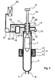
- Fig. 1 is a schematic diagram of an apparatus for sintering a glass preform for an optical fiber according to the present invention.
- a porous glass preform 1 is received inside a muffle tube 2 made of quartz glass and is heated by a heating furnace 6 configured by a heater 3, a heat-insulating material 4 and a water-cooling chamber 5, etc.
- the surroundings of the porous glass preform 1 are filled with atmospheric gas introduced from an atmospheric gas introduction port 7 located at the lower end of the muffle tube 2.
- the atmospheric gas is a mixed gas composed of helium, chlorine and oxygen, etc.
- the pressure inside the muffle tube 2 is measured by a pressure gauge connected to a pressure measurement nozzle 8 provided to the muffle tube 2.
- a pressure gauge may be configured to perform intermittent measurement, in which measurement and pipe purging are repeated, rather than constant measurement.
- an elevating device 9 and a shaft 10 are provided, and the shaft 10 extends into the muffle tube 2 through a first gas seal 16.
- the porous glass preform 1 is rotated and lowered, via the shaft 10, by the elevating device 9 and is introduced into a heating zone within the heating furnace 6.
- an atmospheric gas exhaust tube 12 and an atmospheric gas exhaust pump 13 are provided, and the atmospheric gas within the muffle tube 2 is exhausted to the outside of the muffle tube 2 by means of such tube and pump.
- the exhaust from the atmospheric gas exhaust pump 13 is introduced into a buffering chamber 15, which is provided above the first gas seal 16 so as to cover the shaft, via a buffering gas introduction tube 14.
- a second gas seal 17, through which the shaft passes, is located above the buffering chamber 15.
- the buffering chamber 15 is loosely separated from the upper and lower spaces by the first gas seal 16 and the second gas seal 17.
- the atmospheric gas introduced into the buffering chamber 15 is connected to a main exhaust tube 20, via a buffering chamber exhaust tube 18 and a buffering gas retention vessel 19.
- the main exhaust tube 20 is connected to detoxifying equipment 22, such as a scrubber or the like, via a main exhaust pump 21. At such detoxifying equipment, hazardous components, such as chlorine, contained in the exhaust are removed.
- An external air chamber 23 is provided above the second gas seal 17.
- the external air chamber 23 is connected to the main exhaust tube 20 via an external air chamber exhaust tube 24.
- An atmosphere suction port 25 is provided to the external air chamber 23, and the external air chamber 23 is always ventilated with the external air.
- connection between a buffering gas outlet tube 26 extending from the buffering gas retention vessel 19 and the main exhaust tube 20 has a configuration in which the buffering gas outlet tube 26 having a smaller external diameter is inserted into the main exhaust tube 20 having a larger internal diameter with a gap 27 therebetween.
- Such gap 27 acts as an external air suction port and thus, the external air is sucked into the main exhaust tube 20 along with the exhaust gas.
- a convection prevention member 28 is provided in the vicinity of the lower end of the shaft 10 so as to prevent, to a certain degree, convection occurring in case of the volume of the upper space of the muffle tube 2 increases as the sintering process proceeds and the porous glass preform 1 is pulled down. Thereby, the degree of the internal pressure in the muffle tube 2 becoming negative is decreased.
- the first and second gas seals 16, 17 exist in order to separate the corresponding upper or lower space; however, since the shaft 10 moves in a rotational and vertical manner, it is difficult to achieve a complete gas-tight sealing.
- the atmospheric gas which is exhausted via the atmospheric gas exhaust tube 12, the atmospheric gas exhaust pump 13 and the buffering gas introduction tube 14, fills the buffering chamber 15 and the buffering gas retention vessel 19, and is then released from a distal end of the buffering gas outlet tube 26.
- the distal end of the buffering gas outlet tube 26 is inserted inside the main exhaust tube 20 and is loosely connected thereto. Consequently, the internal pressures in the buffering chamber 15 and the buffering gas retention vessel 19 are automatically maintained at near-atmospheric pressure.
- the gas inside the buffering chamber 15 enters into the muffle tube 2 via the first gas seal 16.
- the components of the gas filled in the buffering chamber 15 are approximately the same as those of the atmospheric gas in the muffle tube 2, the properties of the porous glass preform 1 are not affected by such gas.
- the entirety of the gas filled in the buffering chamber 15 will be sucked into the muffle tube 12.
- gas having components approximately the same as those of the atmospheric gas is supplied from the buffering gas retention vessel 19 with a sufficient capacity, the external air will not be mixed into the muffle tube 2.
- the external chamber 23 is always ventilated and is always at a negative pressure with respect to the external air pressure. Even when the internal pressure in the muffle tube 2 becomes positive and the internal pressure of the buffering chamber 15 also becomes positive as a consequence thereof, thus causing the exhaust gas to enter the external chamber 23 via the second gas seal 17, such exhaust gas will immediately be exhausted via the external air chamber exhaust tube 24 and thus, the exhaust gas will not leak to the atmosphere.
- the first and second gas seals 16, 17 are required to maintain the best sealing properties possible without suppressing the rotational and vertical motion of the shaft 10. Furthermore, materials and structures of the seals are required to resist a high-temperature and chlorine-containing atmosphere.
- the gas seal preferably has a doughnut-shaped structure in which carbon felt is laminated with a fluorine resin (such as PTFE and PFA, etc.) sheet.
- Transparent vitrification of the porous glass preform was performed by means of the sintering apparatus shown in Fig. 1 .
- the introduction gas amount for He was 10 L/min and for Cl 2 it was 2 L/min.
- the flow rate of the exhaust pump was adjusted in such a manner that the hourly average value of the internal pressure in the muffle tube was kept within ⁇ 200 Pa with respect to the external air pressure.
- the momentary value of the internal pressure in the muffle tube ranged between +1000 Pa and -1000 Pa with respect to the external air pressure. No residual bubbles were observed in the transparent-vitrified glass preform. In addition, no deformation of the muffle tube was observed.
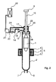
- Transparent vitrification of the porous glass preform was performed by means of the sintering apparatus shown in Fig. 2 , in which the exhaust gas from the atmospheric gas exhaust pump is directly connected to the main exhaust tube.
- the reference numerals in Fig. 2 are in common with those in Fig. 1 .
- the introduction gas amount for He was 10 L/min and for Cl 2 it was 2 L/min.
- the flow rate of the exhaust pump was adjusted in such a manner that the hourly average value of the internal pressure in the muffle tube was kept within ⁇ 200 Pa with respect to the external air pressure.
- the momentary value of the internal pressure in the muffle tube ranged between +1000 Pa and -1000 Pa with respect to the external air pressure. No deformation of the muffle tube was observed; however, residual bubbles were observed in the transparent-vitrified glass preform.
- Transparent vitrification of the porous glass preform was performed by means of the sintering apparatus shown in Fig. 1 .
- the introduction gas amount for He was 10 L/min and for Cl 2 it was 2 L/min.
- the flow rate of the exhaust pump was adjusted in such a manner that the hourly average value of the internal pressure in the muffle tube was kept within the range between +200 Pa and +600 Pa with respect to the external air pressure.
- the momentary value of the internal pressure in the muffle tube ranged between -600 Pa and +1400 Pa with respect to the external air pressure. No residual bubbles were observed in the transparent-vitrified glass preform. However, an expansion in the muffle tube was observed.
- Transparent vitrification of the porous glass preform was performed by means of the sintering apparatus shown in Fig. 1 .
- the introduction gas amount for He was 10 L/min and for Cl 2 it was 2 L/min.
- the flow rate of the exhaust pump was adjusted in such a manner that the hourly average value of the internal pressure in the muffle tube was kept within the range between -600 Pa and -200 Pa with respect to the external air pressure.
- the momentary value of the internal pressure in the muffle tube ranged between -1400 Pa and +600 Pa with respect to the external air pressure. No residual bubbles were observed in the transparent-vitrified glass preform; however, an expansion in the muffle tube was observed.
- the average pressure in the muffle tube at the same level as that of the external air pressure, the occurrence of an expansion or shrinkage of the muffle tube can be suppressed and thus, the service life of the muffle tube can be extended.
- the apparatus for sintering a glass preform for an optical fiber and the sintering method thereof of the present invention even when the internal pressure of the muffle tube temporarily becomes negative due to internal pressure fluctuations in the muffle tube, the degradation of the properties of the optical fiber preform can still be suppressed.
Landscapes
- Chemical & Material Sciences (AREA)
- Engineering & Computer Science (AREA)
- Chemical Kinetics & Catalysis (AREA)
- Physics & Mathematics (AREA)
- General Chemical & Material Sciences (AREA)
- Life Sciences & Earth Sciences (AREA)
- Thermal Sciences (AREA)
- General Life Sciences & Earth Sciences (AREA)
- Geochemistry & Mineralogy (AREA)
- Manufacturing & Machinery (AREA)
- Materials Engineering (AREA)
- Organic Chemistry (AREA)
- Manufacture, Treatment Of Glass Fibers (AREA)
Abstract
Description
- The present invention relates to an apparatus for sintering a glass preform for an optical fiber and to a method thereof for preventing a leakage of gas within a muffle tube as well as an entry of external air into the muffle tube, and for extending the service life of the muffle tube so as to reduce cost.
- The processes referred to as a VAD (vapor-phase axial deposition) process and an OVD (outside vapor deposition) process are known as being processes for manufacturing a glass preform for an optical fiber. In these processes, first, a glass raw material is burnt in flames to generate glass particles and such particles are deposited on a rotating target rod either axially or radially, and then a porous glass preform is produced.
- The porous glass preform produced in this way is heated to 1400-1600 °C in an atmosphere wherein the major component thereof is helium and wherein dehydration gas, such as chlorine for reducing OH groups in glass, and oxygen for reducing binding defects in glass, are added as needed. The reason why helium is used is because it has high thermal conductivity and also because it has a high solubility into glass and thus, bubbles are unlikely to remain in the glass. Prior to transparent vitrification, a dehydration process may be performed at the temperature of 1000-1250 °C. The porous glass preform is heated to 1400-1600 °C and becomes a transparent glass preform.
- The heating of the porous glass preform is carried out in a vessel made of quartz glass, which is referred to as a muffle tube, in an apparatus referred to as a sintering furnace. A heating furnace is arranged around the central part of the muffle tube. At the upper end portion of the muffle tube, a shaft is passed therethrough in order to suspend the porous glass preform. The porous glass preform is heated sequentially from its end portion by passing, in a rotating manner, the heating zone in an upward direction or a downward direction.
- While the glass preform is heated at the central part of the muffle tube, convection tends to occur inside the muffle tube since space exists at the upper portion or lower portion of the glass preform, and thus, the internal pressure in the muffle tube fluctuates.
- Since the shaft passes through the pass-through portion at the upper end of the muffle tube in a rotational and vertical manner, a complete gas-tight sealing is difficult, and when the internal pressure in the muffle tube becomes negative, the external air will be sucked into the muffle tube through the pass-through portion. When the external air is sucked into the muffle tube, the moisture in the external air will also be taken therein and thus, the concentration of OH groups in the glass will be increased, which leads to a degradation of the transmission properties of the optical fiber. In addition, nitrogen gas, which has a larger molecular mass than that of helium, will be taken therein and thus, bubbles tend to remain in the glass, which leads to a decrease in product yield.
- In contrast, when the internal pressure in the muffle tube becomes positive, chlorine, which is a component of the atmospheric gas in the muffle tube, will be released into the external air. Since chlorine is a toxic and corrosive gas, it is unpreferable for work environments. Chlorine will further shorten the service life of the apparatus by oxidizing the same and the oxidization of the apparatus will lead to dust arising, which leads to a degradation of the product's properties and a decrease in product yield.
- Moreover, when the pressure difference between outside and inside of the muffle tube becomes large, the muffle tube made of quartz glass will shrink or expand due to such pressure difference. When the muffle tube shrinks, the maximum external diameter of the porous glass preform processable in the muffle tube will be decreased. Further, when the muffle tube expands and sticks to the heating furnace, the service life of the muffle tube will be reduced.
- In order to solve the problems above, in
JP 4737031 B - By the method described in
JP 4737031 B - In addition, there is a method in which both the introduction flow rate and the exhaust flow rate of atmospheric gas for suppressing pressure fluctuations. However, in this case as well, a great amount of expensive helium is needed and thus, the running costs will be high.
- In order to solve the problems above, in the apparatus for sintering a glass preform for an optical fiber according to the present invention, the glass preform for the optical fiber is received in a muffle tube and heated in an atmospheric gas while being suspended on a shaft and supported thereon. The apparatus includes a first gas seal, through which the shaft is inserted, provided at an upper end of the muffle tube; a buffering chamber that is provided above the first gas seal and that covers the shaft; a second gas seal, through which shaft is inserted, provided at an upper end of the buffering chamber; and a unit that introduces the atmospheric gas exhausted from the muffle tube into the buffering chamber.
- Due to the presence of the first gas seal, the propagation of internal pressure fluctuations in the muffle tube to the buffering chamber is relaxed, and moreover, the entry of the external air components into the muffle tube via the first gas seal is prevented, in case of the internal pressure of the muffle tube becomes negative.
- By introducing the atmospheric gas exhausted from the muffle tube into the buffering chamber, the gas components in the buffering chamber become close to those of the atmospheric gas in the muffle tube and thus, the entry of the external air components into the muffle tube via the first gas seal can be reduced, in case of the internal pressure in the muffle tube becomes negative.
- Due to the presence of the second gas seal, the leakage of the atmospheric gas components in the muffle tube introduced into the buffering chamber to the exterior is suppressed.
- Preferably, the atmospheric gas is exhausted from the muffle tube, via the atmospheric gas exhaust pump, so that the atmospheric gas is introduced into the buffering chamber. As a consequence, the atmospheric gas exhausted from the muffle tube is efficiently introduced into the buffering chamber. In addition, by adjusting the flow rate of the atmospheric gas exhausted from the muffle tube, via the output of the exhaust pump and a valve provided to the exhaust pump, the internal pressure of the muffle tube can be adjusted.
- Preferably, an external air chamber is provided above the second gas seal so as to cover the shaft and to introduce the external air therein. Consequently, the leakage of the atmospheric gas into the external air is significantly reduced.
- Preferably, the internal pressure of the buffering chamber is approximately equal to the external air pressure. When the internal pressure of the buffering chamber is too high, the amount of the atmospheric gas leaking to the external air increases. In contrast, when the internal pressure of the buffering chamber is too low, the external air enters into the buffering chamber and accordingly, the external air enters to the muffle tube via the first gas seal, in case of the internal pressure of the muffle tube becomes negative.
- Preferably, an external air suction port is provided midway along a pipe connecting the buffering chamber exhaust tube and the main exhaust tube. The internal pressure of the buffering chamber can easily adjusted to be approximately equal to the external air pressure without the need for any complicated devices.
- Such external air suction port may be provided as a gap at the connection between the main exhaust tube and the pipe. By avoiding a tight connection at the connection with the pipe, while ensuring the capability of exhaust leading to detoxifying equipment, etc., the ability to suck the external air is also provided.
- More preferably, a buffering gas retention vessel is provided midway along a pipe connecting the buffering chamber exhaust tube and the external air suction port. Most of the gas components in the buffering gas retention vessel originate from the atmospheric gas in the muffle tube, and thus, the entry of the external air into the muffle tube in case of the external air flows back due to the negative pressure in the muffle tube, is prevented.
- Preferably, a convection prevention member is provided in the vicinity of a lower end of the shaft to narrow down the gap between the outer circumference of the shaft and the inner circumference of the muffle tube. Due to the presence of such convection prevention member, the internal pressure fluctuations in the muffle tube are reduced and the possibility that the external air enter to the muffle tube is also reduced.
- Preferably, the first gas seal and the second gas seal respectively have a laminated structure of a felt-like sheet and a gas-tight sheet. Preferably, a carbon felt sheet is used for the felt-like sheet and a fluorine resin sheet is used for the gas-tight sheet. Both carbon felt sheet and fluorine resin sheet excel in terms of heat resistance and chlorine resistance and thus, they can extend the service life of the members.
- Preferably, the flow rate of the atmospheric gas exhaust pump is adjusted so that to an hourly average pressure in the muffle tube is set within ± 200 Pa with respect to the external air pressure. This is because, when the difference between the average pressure in the muffle tube and the external air pressure becomes large, the high-temperature part of the muffle tube will expand or shrink. In particular, when the high-temperature part of the muffle tube expands, the muffle tube and the heating furnace may come into contact with each other and this may reduce service life for the muffle tube.
- According to the present invention, even when the internal pressure of the muffle tube temporarily becomes negative, the suction of the external air into the muffle tube can still be prevented and thus, the degradation of the optical fiber preform properties can still be suppressed.
- An apparatus for sintering a glass preform for an optical fiber according to the present invention will be described hereinafter, with reference to the drawings.
-
Fig. 1 is a schematic diagram of an embodiment of an apparatus for sintering a glass preform for an optical fiber according to the present invention. -
Fig. 2 is a schematic diagram of a conventional apparatus for sintering a glass preform for an optical fiber. -
Fig. 1 is a schematic diagram of an apparatus for sintering a glass preform for an optical fiber according to the present invention. - A
porous glass preform 1 is received inside amuffle tube 2 made of quartz glass and is heated by a heating furnace 6 configured by a heater 3, a heat-insulating material 4 and a water-cooling chamber 5, etc. - The surroundings of the
porous glass preform 1 are filled with atmospheric gas introduced from an atmosphericgas introduction port 7 located at the lower end of themuffle tube 2. The atmospheric gas is a mixed gas composed of helium, chlorine and oxygen, etc. The pressure inside themuffle tube 2 is measured by a pressure gauge connected to apressure measurement nozzle 8 provided to themuffle tube 2. In order to prevent degradation due to the corrosive chlorine, such pressure gauge may be configured to perform intermittent measurement, in which measurement and pipe purging are repeated, rather than constant measurement. - At the upper portion, an
elevating device 9 and ashaft 10 are provided, and theshaft 10 extends into themuffle tube 2 through a first gas seal 16. Theporous glass preform 1 is rotated and lowered, via theshaft 10, by the elevatingdevice 9 and is introduced into a heating zone within the heating furnace 6. - At the upper portion of the
muffle tube 2, an atmosphericgas exhaust tube 12 and an atmosphericgas exhaust pump 13 are provided, and the atmospheric gas within themuffle tube 2 is exhausted to the outside of themuffle tube 2 by means of such tube and pump. The exhaust from the atmosphericgas exhaust pump 13 is introduced into abuffering chamber 15, which is provided above the first gas seal 16 so as to cover the shaft, via a bufferinggas introduction tube 14. Asecond gas seal 17, through which the shaft passes, is located above thebuffering chamber 15. Thebuffering chamber 15 is loosely separated from the upper and lower spaces by the first gas seal 16 and thesecond gas seal 17. - The atmospheric gas introduced into the
buffering chamber 15 is connected to amain exhaust tube 20, via a buffering chamber exhaust tube 18 and a bufferinggas retention vessel 19. Themain exhaust tube 20 is connected to detoxifyingequipment 22, such as a scrubber or the like, via amain exhaust pump 21. At such detoxifying equipment, hazardous components, such as chlorine, contained in the exhaust are removed. - An
external air chamber 23 is provided above thesecond gas seal 17. Theexternal air chamber 23 is connected to themain exhaust tube 20 via an external airchamber exhaust tube 24. Anatmosphere suction port 25 is provided to theexternal air chamber 23, and theexternal air chamber 23 is always ventilated with the external air. - The connection between a buffering
gas outlet tube 26 extending from the bufferinggas retention vessel 19 and themain exhaust tube 20 has a configuration in which the bufferinggas outlet tube 26 having a smaller external diameter is inserted into themain exhaust tube 20 having a larger internal diameter with agap 27 therebetween.Such gap 27 acts as an external air suction port and thus, the external air is sucked into themain exhaust tube 20 along with the exhaust gas. - A
convection prevention member 28 is provided in the vicinity of the lower end of theshaft 10 so as to prevent, to a certain degree, convection occurring in case of the volume of the upper space of themuffle tube 2 increases as the sintering process proceeds and theporous glass preform 1 is pulled down. Thereby, the degree of the internal pressure in themuffle tube 2 becoming negative is decreased. - The first and second gas seals 16, 17 exist in order to separate the corresponding upper or lower space; however, since the
shaft 10 moves in a rotational and vertical manner, it is difficult to achieve a complete gas-tight sealing. - The atmospheric gas, which is exhausted via the atmospheric
gas exhaust tube 12, the atmosphericgas exhaust pump 13 and the bufferinggas introduction tube 14, fills thebuffering chamber 15 and the bufferinggas retention vessel 19, and is then released from a distal end of the bufferinggas outlet tube 26. The distal end of the bufferinggas outlet tube 26 is inserted inside themain exhaust tube 20 and is loosely connected thereto. Consequently, the internal pressures in thebuffering chamber 15 and the bufferinggas retention vessel 19 are automatically maintained at near-atmospheric pressure. - When the internal pressure in the
muffle tube 2 is changed and becomes negative, the gas inside thebuffering chamber 15 enters into themuffle tube 2 via the first gas seal 16. However, since the components of the gas filled in thebuffering chamber 15 are approximately the same as those of the atmospheric gas in themuffle tube 2, the properties of theporous glass preform 1 are not affected by such gas. Depending on the degree of the negative pressure and on duration of negative pressure, the entirety of the gas filled in thebuffering chamber 15 will be sucked into themuffle tube 12. However, since gas having components approximately the same as those of the atmospheric gas is supplied from the bufferinggas retention vessel 19 with a sufficient capacity, the external air will not be mixed into themuffle tube 2. - The
external chamber 23 is always ventilated and is always at a negative pressure with respect to the external air pressure. Even when the internal pressure in themuffle tube 2 becomes positive and the internal pressure of thebuffering chamber 15 also becomes positive as a consequence thereof, thus causing the exhaust gas to enter theexternal chamber 23 via thesecond gas seal 17, such exhaust gas will immediately be exhausted via the external airchamber exhaust tube 24 and thus, the exhaust gas will not leak to the atmosphere. - The first and second gas seals 16, 17 are required to maintain the best sealing properties possible without suppressing the rotational and vertical motion of the
shaft 10. Furthermore, materials and structures of the seals are required to resist a high-temperature and chlorine-containing atmosphere. In order to achieve the above, the gas seal preferably has a doughnut-shaped structure in which carbon felt is laminated with a fluorine resin (such as PTFE and PFA, etc.) sheet. - Transparent vitrification of the porous glass preform was performed by means of the sintering apparatus shown in
Fig. 1 . The introduction gas amount for He was 10 L/min and for Cl2 it was 2 L/min. The flow rate of the exhaust pump was adjusted in such a manner that the hourly average value of the internal pressure in the muffle tube was kept within ± 200 Pa with respect to the external air pressure. The momentary value of the internal pressure in the muffle tube ranged between +1000 Pa and -1000 Pa with respect to the external air pressure. No residual bubbles were observed in the transparent-vitrified glass preform. In addition, no deformation of the muffle tube was observed. - Transparent vitrification of the porous glass preform was performed by means of the sintering apparatus shown in
Fig. 2 , in which the exhaust gas from the atmospheric gas exhaust pump is directly connected to the main exhaust tube. The reference numerals inFig. 2 are in common with those inFig. 1 . The introduction gas amount for He was 10 L/min and for Cl2 it was 2 L/min. The flow rate of the exhaust pump was adjusted in such a manner that the hourly average value of the internal pressure in the muffle tube was kept within ± 200 Pa with respect to the external air pressure. The momentary value of the internal pressure in the muffle tube ranged between +1000 Pa and -1000 Pa with respect to the external air pressure. No deformation of the muffle tube was observed; however, residual bubbles were observed in the transparent-vitrified glass preform. - Transparent vitrification of the porous glass preform was performed by means of the sintering apparatus shown in
Fig. 1 . The introduction gas amount for He was 10 L/min and for Cl2 it was 2 L/min. The flow rate of the exhaust pump was adjusted in such a manner that the hourly average value of the internal pressure in the muffle tube was kept within the range between +200 Pa and +600 Pa with respect to the external air pressure. The momentary value of the internal pressure in the muffle tube ranged between -600 Pa and +1400 Pa with respect to the external air pressure. No residual bubbles were observed in the transparent-vitrified glass preform. However, an expansion in the muffle tube was observed. - Transparent vitrification of the porous glass preform was performed by means of the sintering apparatus shown in
Fig. 1 . The introduction gas amount for He was 10 L/min and for Cl2 it was 2 L/min. The flow rate of the exhaust pump was adjusted in such a manner that the hourly average value of the internal pressure in the muffle tube was kept within the range between -600 Pa and -200 Pa with respect to the external air pressure. The momentary value of the internal pressure in the muffle tube ranged between -1400 Pa and +600 Pa with respect to the external air pressure. No residual bubbles were observed in the transparent-vitrified glass preform; however, an expansion in the muffle tube was observed. - As is clear from the descriptions above, by making use of an apparatus for sintering a glass preform for an optical fiber according to the embodiment, even when the internal pressure of the muffle tube temporarily becomes negative due to internal pressure fluctuations in the muffle tube, the suction of the external air into the muffle tube can still be prevented and thus, the degradation of the properties of the optical fiber preform can still be suppressed.
- In addition, by keeping the average pressure in the muffle tube at the same level as that of the external air pressure, the occurrence of an expansion or shrinkage of the muffle tube can be suppressed and thus, the service life of the muffle tube can be extended.
- Furthermore, since there is no need to constantly control the gas flow rate or exhaust amount depending on the internal pressure of the muffle tube, the cost for producing apparatuses and the failure rates thereof can both be reduced.
- According to the apparatus for sintering a glass preform for an optical fiber and the sintering method thereof of the present invention, even when the internal pressure of the muffle tube temporarily becomes negative due to internal pressure fluctuations in the muffle tube, the degradation of the properties of the optical fiber preform can still be suppressed.
-
- 1.
- Porous glass preform
- 2.
- Muffle tube
- 3.
- Heater
- 4.
- Heat-insulating material
- 5.
- Water-cooling chamber
- 6.
- Hearting furnace
- 7.
- Atmospheric gas introduction port
- 8.
- Pressure measurement nozzle
- 9.
- Elevating device
- 10.
- Shaft
- 12.
- Atmospheric gas exhaust tube
- 13.
- Atmospheric gas exhaust pump
- 14.
- Buffering gas introduction tube
- 15.
- Buffering chamber
- 16.
- First gas seal
- 17.
- Second gas seal
- 18.
- Buffering chamber exhaust tube
- 19.
- Buffering gas retention vessel
- 20.
- Main exhaust tube
- 21.
- Main exhaust pump
- 22.
- Detoxifying equipment
- 23.
- External air chamber
- 24.
- External air chamber exhaust tube
- 25.
- Atmosphere suction port
- 26.
- Buffering gas outlet tube
- 27.
- Gap
- 28.
- Convection prevention member
Claims (14)
- An apparatus for sintering a glass preform for an optical fiber, the glass preform for the optical fiber being received in a muffle tube and being heated in an atmospheric gas while being suspended on a shaft and supported thereon, comprising:a first gas seal that is provided at an upper end of the muffle tube, the shaft being inserted therethrough;a buffering chamber that is provided above the first gas seal and that covers the shaft;a second gas seal that is provided at an upper end of the buffering chamber, the shaft being inserted therethrough; anda unit that introduces the atmospheric gas exhausted from the muffle tube into the buffering chamber.
- The apparatus for sintering a glass preform for an optical fiber according to claim 1, further comprising:an atmospheric gas exhaust pump that exhausted the atmospheric gas from the muffle tube,wherein the atmospheric gas exhausted by the atmospheric gas exhaust pump is introduced into the buffering chamber.
- The apparatus for sintering a glass preform for an optical fiber according to claim 1 or 2, further comprising:an external air chamber that is provided above the second gas seal and that covers the shaft,wherein external air is introduced into the external air chamber.
- The apparatus for sintering a glass preform for an optical fiber according to any of claims 1 to 3, further comprising:a buffering chamber internal pressure adjustment unit that causes an internal pressure of the buffering chamber to be approximately equal to an external air pressure.
- The apparatus for sintering a glass preform for an optical fiber according to claim 4, wherein
the buffering chamber internal pressure adjustment unit includes:a buffering chamber exhaust tube that is provided to the buffering chamber;a main exhaust tube that is connected to the buffering chamber exhaust tube; andan external air suction port that is provided between the buffering exhaust tube and the main exhaust tube. - The apparatus for sintering a glass preform for an optical fiber according to claim 5, further comprising a buffering gas retention vessel between the buffering chamber exhaust tube and the external air suction port.
- The apparatus for sintering a glass preform for an optical fiber according to any of claims 1 to 6, further comprising a convection prevention member, in the vicinity of a lower end of the shaft, that narrows down a gap between an outer circumference of the shaft and an inner circumference of the muffle tube.
- The apparatus for sintering a glass preform for an optical fiber according to any of claims 1 to 7, wherein the first gas seal and the second gas seal respectively have a laminated structure of a felt-like sheet and a gas-tight sheet.
- The apparatus for sintering a glass preform for an optical fiber according to claim 8, wherein the felt-like sheet is a carbon felt sheet.
- The apparatus for sintering a glass preform for an optical fiber according to claim 8 or 9, wherein the gas-tight sheet is a fluorine resin sheet.
- A method for sintering a glass preform for an optical fiber, the glass preform for the optical fiber being received in a muffle tube and being heated in an atmospheric gas while being suspended on a shaft and supported thereon, the method comprising the steps of:providing a first gas seal having the shaft inserted therethrough at an upper face of the muffle tube;providing a buffering chamber above the first gas seal so as to cover the shaft;providing a second gas seal having the shaft inserted therethrough at an upper face of the buffering chamber; andperforming heating while introducing the atmospheric gas exhausted from the muffle tube into the buffering chamber.
- The method for sintering a glass preform for an optical fiber according to claim 11, further comprising the steps of:providing an external air chamber above the second gas seal so as to cover the shaft; andintroducing external air into the external air chamber.
- The method for sintering a glass preform for an optical fiber according to claim 11 or 12, further comprising the step of:causing an internal pressure of the buffering chamber to be approximately equal to an external air pressure.
- The method for sintering a glass preform for an optical fiber according to any of claims 11 to 13, further comprising the step of:adjusting an hourly average value of the internal pressure in the muffle tube to be within ± 200 Pa with respect to the external air pressure.
Applications Claiming Priority (1)
| Application Number | Priority Date | Filing Date | Title |
|---|---|---|---|
| JP2013106731A JP5968262B2 (en) | 2013-05-21 | 2013-05-21 | Sintering apparatus and sintering method for glass preform for optical fiber |
Publications (2)
| Publication Number | Publication Date |
|---|---|
| EP2805928A1 true EP2805928A1 (en) | 2014-11-26 |
| EP2805928B1 EP2805928B1 (en) | 2017-12-06 |
Family
ID=50721588
Family Applications (1)
| Application Number | Title | Priority Date | Filing Date |
|---|---|---|---|
| EP14167633.8A Not-in-force EP2805928B1 (en) | 2013-05-21 | 2014-05-09 | Method and apparatus for sintering a glass preform for an optical fiber |
Country Status (5)
| Country | Link |
|---|---|
| US (1) | US9422185B2 (en) |
| EP (1) | EP2805928B1 (en) |
| JP (1) | JP5968262B2 (en) |
| CN (1) | CN104176925B (en) |
| IN (1) | IN2014DE01310A (en) |
Families Citing this family (18)
| Publication number | Priority date | Publication date | Assignee | Title |
|---|---|---|---|---|
| JP6184360B2 (en) * | 2014-03-26 | 2017-08-23 | 信越化学工業株式会社 | Sintering equipment for glass preform for optical fiber |
| US9751796B2 (en) * | 2015-03-24 | 2017-09-05 | Shin-Etsu Chemical Co., Ltd. | Sintering apparatus and method for sintering |
| JP6565556B2 (en) * | 2015-09-30 | 2019-08-28 | 住友電気工業株式会社 | Glass base material lifting device |
| JP2017088458A (en) * | 2015-11-13 | 2017-05-25 | 住友電気工業株式会社 | Porous glass base material dehydration sintering apparatus and dehydration sintering method |
| JP6573560B2 (en) * | 2016-03-03 | 2019-09-11 | 信越化学工業株式会社 | Heat treatment equipment |
| JP6621388B2 (en) * | 2016-08-02 | 2019-12-18 | 信越化学工業株式会社 | Sintering equipment |
| CN106116122B (en) * | 2016-08-31 | 2018-12-25 | 中国建筑材料科学研究总院 | Prepare the sintering equipment and system of quartz glass |
| JP6784123B2 (en) * | 2016-09-29 | 2020-11-11 | 住友電気工業株式会社 | Manufacturing method and manufacturing equipment for glass base material |
| CN110054411B (en) * | 2017-02-28 | 2021-08-06 | 天津富通集团有限公司 | High temperature chamber for large-scale optical fiber preform production process |
| CN110550857B (en) * | 2019-08-19 | 2022-06-24 | 湖州维德光电科技有限公司 | Optical fiber perform gaseous economizer |
| JP7404931B2 (en) * | 2020-02-26 | 2023-12-26 | 住友電気工業株式会社 | Glass base material manufacturing equipment |
| US20230397568A1 (en) | 2020-10-23 | 2023-12-14 | Automated Pet Care Products Llc | Smart litter device with entry barrier |
| CN112645583A (en) * | 2021-01-13 | 2021-04-13 | 烽火通信科技股份有限公司 | System and method for automatically controlling pressure in optical fiber preform sintering furnace |
| JP7558894B2 (en) * | 2021-05-31 | 2024-10-01 | 古河電気工業株式会社 | Optical fiber preform manufacturing apparatus and method for manufacturing optical fiber preform |
| CN115974400A (en) * | 2022-12-24 | 2023-04-18 | 藤仓烽火光电材料科技有限公司 | Loose body sintering device and loose body sintering method |
| WO2025028455A1 (en) * | 2023-07-28 | 2025-02-06 | 住友電気工業株式会社 | Apparatus and method for manufacturing glass preform |
| WO2026010939A2 (en) | 2024-07-03 | 2026-01-08 | Automated Pet Care Products, Llc D/B/A Whisker | Litter dispenser for litter device |
| US20260007117A1 (en) | 2024-07-03 | 2026-01-08 | Automated Pet Care Products, Llc D/B/A Whisker | Weight Based Systems and Methods for Automatically Identifying Animal Waste |
Citations (6)
| Publication number | Priority date | Publication date | Assignee | Title |
|---|---|---|---|---|
| JPS63159232A (en) * | 1986-12-22 | 1988-07-02 | Mitsubishi Cable Ind Ltd | Production apparatus for optical fiber preform |
| JP2002226218A (en) * | 2001-01-29 | 2002-08-14 | Sumitomo Electric Ind Ltd | Furnace tube top lid for glass porous base material sintering furnace and method for sintering glass porous base material |
| JP2008105904A (en) * | 2006-10-26 | 2008-05-08 | Sumitomo Electric Ind Ltd | Glass base material manufacturing method and manufacturing apparatus |
| JP2008179517A (en) * | 2007-01-25 | 2008-08-07 | Sumitomo Electric Ind Ltd | Glass base material manufacturing apparatus and manufacturing method |
| JP2009120451A (en) * | 2007-11-16 | 2009-06-04 | Sumitomo Electric Ind Ltd | Glass base material manufacturing method and manufacturing apparatus |
| JP2009292658A (en) * | 2008-06-02 | 2009-12-17 | Sumitomo Electric Ind Ltd | Dehydration sintering apparatus for porous glass preform and exhaust control method |
Family Cites Families (3)
| Publication number | Priority date | Publication date | Assignee | Title |
|---|---|---|---|---|
| JP2000351643A (en) * | 1999-06-08 | 2000-12-19 | Fujikura Ltd | Dehydration sintering device for optical fiber preform |
| JP2003212557A (en) * | 2002-01-23 | 2003-07-30 | Sumitomo Electric Ind Ltd | Manufacturing method and manufacturing apparatus for glass base material |
| JP2008184372A (en) * | 2007-01-31 | 2008-08-14 | Sumitomo Electric Ind Ltd | Glass base material manufacturing apparatus and manufacturing method |
-
2013
- 2013-05-21 JP JP2013106731A patent/JP5968262B2/en active Active
-
2014
- 2014-05-09 EP EP14167633.8A patent/EP2805928B1/en not_active Not-in-force
- 2014-05-13 US US14/276,263 patent/US9422185B2/en not_active Expired - Fee Related
- 2014-05-15 CN CN201410204678.1A patent/CN104176925B/en not_active Expired - Fee Related
- 2014-05-16 IN IN1310DE2014 patent/IN2014DE01310A/en unknown
Patent Citations (7)
| Publication number | Priority date | Publication date | Assignee | Title |
|---|---|---|---|---|
| JPS63159232A (en) * | 1986-12-22 | 1988-07-02 | Mitsubishi Cable Ind Ltd | Production apparatus for optical fiber preform |
| JP2002226218A (en) * | 2001-01-29 | 2002-08-14 | Sumitomo Electric Ind Ltd | Furnace tube top lid for glass porous base material sintering furnace and method for sintering glass porous base material |
| JP2008105904A (en) * | 2006-10-26 | 2008-05-08 | Sumitomo Electric Ind Ltd | Glass base material manufacturing method and manufacturing apparatus |
| JP4737031B2 (en) | 2006-10-26 | 2011-07-27 | 住友電気工業株式会社 | Glass base material manufacturing method and manufacturing apparatus |
| JP2008179517A (en) * | 2007-01-25 | 2008-08-07 | Sumitomo Electric Ind Ltd | Glass base material manufacturing apparatus and manufacturing method |
| JP2009120451A (en) * | 2007-11-16 | 2009-06-04 | Sumitomo Electric Ind Ltd | Glass base material manufacturing method and manufacturing apparatus |
| JP2009292658A (en) * | 2008-06-02 | 2009-12-17 | Sumitomo Electric Ind Ltd | Dehydration sintering apparatus for porous glass preform and exhaust control method |
Also Published As
| Publication number | Publication date |
|---|---|
| US9422185B2 (en) | 2016-08-23 |
| IN2014DE01310A (en) | 2015-06-12 |
| EP2805928B1 (en) | 2017-12-06 |
| JP2014227310A (en) | 2014-12-08 |
| CN104176925B (en) | 2018-05-04 |
| CN104176925A (en) | 2014-12-03 |
| US20140345332A1 (en) | 2014-11-27 |
| JP5968262B2 (en) | 2016-08-10 |
Similar Documents
| Publication | Publication Date | Title |
|---|---|---|
| EP2805928B1 (en) | Method and apparatus for sintering a glass preform for an optical fiber | |
| JP5202810B2 (en) | Graphite heating furnace and optical fiber manufacturing method | |
| CN105669019B (en) | The manufacturing device and its manufacturing method of preform | |
| CN111116036B (en) | Method for manufacturing glass preform for optical fiber | |
| JP3949425B2 (en) | Heat treatment apparatus and method for optical fiber preform | |
| US6845636B2 (en) | Apparatus for dehydrating and consolidating an optical fiber preform and method of the same | |
| US8037717B2 (en) | Methods and apparatus for pulsed doping or drying a soot preform | |
| CN205616787U (en) | Optical fiber perform's manufacturing installation | |
| EP4282838B1 (en) | Apparatus for drying and/or consolidating a preform for optical fibres | |
| JP2012509245A (en) | Apparatus and method for sintering optical fiber preforms | |
| EP2789590A1 (en) | Sintering apparatus | |
| JP5304031B2 (en) | Porous glass base material dehydration sintering apparatus and exhaust control method thereof | |
| CN107635936B (en) | Rotating lead-through for mounting a rotating substrate tube in a lathe, a CVD lathe, and a corresponding method of using a CVD lathe | |
| JP2008179517A (en) | Glass base material manufacturing apparatus and manufacturing method | |
| CN109721236B (en) | Apparatus and method for manufacturing glass base material | |
| JP6519488B2 (en) | Method of manufacturing optical fiber base material | |
| JP2008184372A (en) | Glass base material manufacturing apparatus and manufacturing method | |
| JP4403011B2 (en) | Optical fiber preform manufacturing method and optical fiber preform manufacturing apparatus | |
| JP6540450B2 (en) | Method of manufacturing glass base material | |
| JP2002226218A (en) | Furnace tube top lid for glass porous base material sintering furnace and method for sintering glass porous base material | |
| JP4737031B2 (en) | Glass base material manufacturing method and manufacturing apparatus | |
| US11554981B2 (en) | Apparatuses and methods for processing optical fiber preforms | |
| JP6539609B2 (en) | Sintering apparatus and sintering method | |
| JP2003238188A (en) | Optical fiber preform manufacturing equipment | |
| CN119822626A (en) | Optical fiber preform sintering device and method |
Legal Events
| Date | Code | Title | Description |
|---|---|---|---|
| PUAI | Public reference made under article 153(3) epc to a published international application that has entered the european phase |
Free format text: ORIGINAL CODE: 0009012 |
|
| 17P | Request for examination filed |
Effective date: 20140509 |
|
| AK | Designated contracting states |
Kind code of ref document: A1 Designated state(s): AL AT BE BG CH CY CZ DE DK EE ES FI FR GB GR HR HU IE IS IT LI LT LU LV MC MK MT NL NO PL PT RO RS SE SI SK SM TR |
|
| AX | Request for extension of the european patent |
Extension state: BA ME |
|
| R17P | Request for examination filed (corrected) |
Effective date: 20150423 |
|
| RBV | Designated contracting states (corrected) |
Designated state(s): AL AT BE BG CH CY CZ DE DK EE ES FI FR GB GR HR HU IE IS IT LI LT LU LV MC MK MT NL NO PL PT RO RS SE SI SK SM TR |
|
| RIN1 | Information on inventor provided before grant (corrected) |
Inventor name: OTOSAKA, TETSUYA Inventor name: UCHIDA, KAZUYA |
|
| 17Q | First examination report despatched |
Effective date: 20151202 |
|
| GRAP | Despatch of communication of intention to grant a patent |
Free format text: ORIGINAL CODE: EPIDOSNIGR1 |
|
| INTG | Intention to grant announced |
Effective date: 20170601 |
|
| GRAS | Grant fee paid |
Free format text: ORIGINAL CODE: EPIDOSNIGR3 |
|
| GRAJ | Information related to disapproval of communication of intention to grant by the applicant or resumption of examination proceedings by the epo deleted |
Free format text: ORIGINAL CODE: EPIDOSDIGR1 |
|
| GRAL | Information related to payment of fee for publishing/printing deleted |
Free format text: ORIGINAL CODE: EPIDOSDIGR3 |
|
| GRAR | Information related to intention to grant a patent recorded |
Free format text: ORIGINAL CODE: EPIDOSNIGR71 |
|
| GRAA | (expected) grant |
Free format text: ORIGINAL CODE: 0009210 |
|
| INTC | Intention to grant announced (deleted) | ||
| RIN1 | Information on inventor provided before grant (corrected) |
Inventor name: UCHIDA, KAZUYA Inventor name: OTOSAKA, TETSUYA |
|
| AK | Designated contracting states |
Kind code of ref document: B1 Designated state(s): AL AT BE BG CH CY CZ DE DK EE ES FI FR GB GR HR HU IE IS IT LI LT LU LV MC MK MT NL NO PL PT RO RS SE SI SK SM TR |
|
| INTG | Intention to grant announced |
Effective date: 20171030 |
|
| REG | Reference to a national code |
Ref country code: GB Ref legal event code: FG4D |
|
| REG | Reference to a national code |
Ref country code: AT Ref legal event code: REF Ref document number: 952210 Country of ref document: AT Kind code of ref document: T Effective date: 20171215 Ref country code: CH Ref legal event code: EP |
|
| REG | Reference to a national code |
Ref country code: IE Ref legal event code: FG4D |
|
| REG | Reference to a national code |
Ref country code: DE Ref legal event code: R096 Ref document number: 602014018092 Country of ref document: DE |
|
| REG | Reference to a national code |
Ref country code: NL Ref legal event code: MP Effective date: 20171206 |
|
| REG | Reference to a national code |
Ref country code: FR Ref legal event code: PLFP Year of fee payment: 5 |
|
| REG | Reference to a national code |
Ref country code: LT Ref legal event code: MG4D |
|
| PG25 | Lapsed in a contracting state [announced via postgrant information from national office to epo] |
Ref country code: FI Free format text: LAPSE BECAUSE OF FAILURE TO SUBMIT A TRANSLATION OF THE DESCRIPTION OR TO PAY THE FEE WITHIN THE PRESCRIBED TIME-LIMIT Effective date: 20171206 Ref country code: LT Free format text: LAPSE BECAUSE OF FAILURE TO SUBMIT A TRANSLATION OF THE DESCRIPTION OR TO PAY THE FEE WITHIN THE PRESCRIBED TIME-LIMIT Effective date: 20171206 Ref country code: ES Free format text: LAPSE BECAUSE OF FAILURE TO SUBMIT A TRANSLATION OF THE DESCRIPTION OR TO PAY THE FEE WITHIN THE PRESCRIBED TIME-LIMIT Effective date: 20171206 Ref country code: SE Free format text: LAPSE BECAUSE OF FAILURE TO SUBMIT A TRANSLATION OF THE DESCRIPTION OR TO PAY THE FEE WITHIN THE PRESCRIBED TIME-LIMIT Effective date: 20171206 Ref country code: NO Free format text: LAPSE BECAUSE OF FAILURE TO SUBMIT A TRANSLATION OF THE DESCRIPTION OR TO PAY THE FEE WITHIN THE PRESCRIBED TIME-LIMIT Effective date: 20180306 |
|
| REG | Reference to a national code |
Ref country code: AT Ref legal event code: MK05 Ref document number: 952210 Country of ref document: AT Kind code of ref document: T Effective date: 20171206 |
|
| PG25 | Lapsed in a contracting state [announced via postgrant information from national office to epo] |
Ref country code: RS Free format text: LAPSE BECAUSE OF FAILURE TO SUBMIT A TRANSLATION OF THE DESCRIPTION OR TO PAY THE FEE WITHIN THE PRESCRIBED TIME-LIMIT Effective date: 20171206 Ref country code: HR Free format text: LAPSE BECAUSE OF FAILURE TO SUBMIT A TRANSLATION OF THE DESCRIPTION OR TO PAY THE FEE WITHIN THE PRESCRIBED TIME-LIMIT Effective date: 20171206 Ref country code: BG Free format text: LAPSE BECAUSE OF FAILURE TO SUBMIT A TRANSLATION OF THE DESCRIPTION OR TO PAY THE FEE WITHIN THE PRESCRIBED TIME-LIMIT Effective date: 20180306 Ref country code: LV Free format text: LAPSE BECAUSE OF FAILURE TO SUBMIT A TRANSLATION OF THE DESCRIPTION OR TO PAY THE FEE WITHIN THE PRESCRIBED TIME-LIMIT Effective date: 20171206 Ref country code: GR Free format text: LAPSE BECAUSE OF FAILURE TO SUBMIT A TRANSLATION OF THE DESCRIPTION OR TO PAY THE FEE WITHIN THE PRESCRIBED TIME-LIMIT Effective date: 20180307 |
|
| PG25 | Lapsed in a contracting state [announced via postgrant information from national office to epo] |
Ref country code: NL Free format text: LAPSE BECAUSE OF FAILURE TO SUBMIT A TRANSLATION OF THE DESCRIPTION OR TO PAY THE FEE WITHIN THE PRESCRIBED TIME-LIMIT Effective date: 20171206 |
|
| PG25 | Lapsed in a contracting state [announced via postgrant information from national office to epo] |
Ref country code: CZ Free format text: LAPSE BECAUSE OF FAILURE TO SUBMIT A TRANSLATION OF THE DESCRIPTION OR TO PAY THE FEE WITHIN THE PRESCRIBED TIME-LIMIT Effective date: 20171206 Ref country code: EE Free format text: LAPSE BECAUSE OF FAILURE TO SUBMIT A TRANSLATION OF THE DESCRIPTION OR TO PAY THE FEE WITHIN THE PRESCRIBED TIME-LIMIT Effective date: 20171206 Ref country code: SK Free format text: LAPSE BECAUSE OF FAILURE TO SUBMIT A TRANSLATION OF THE DESCRIPTION OR TO PAY THE FEE WITHIN THE PRESCRIBED TIME-LIMIT Effective date: 20171206 |
|
| PG25 | Lapsed in a contracting state [announced via postgrant information from national office to epo] |
Ref country code: AT Free format text: LAPSE BECAUSE OF FAILURE TO SUBMIT A TRANSLATION OF THE DESCRIPTION OR TO PAY THE FEE WITHIN THE PRESCRIBED TIME-LIMIT Effective date: 20171206 Ref country code: RO Free format text: LAPSE BECAUSE OF FAILURE TO SUBMIT A TRANSLATION OF THE DESCRIPTION OR TO PAY THE FEE WITHIN THE PRESCRIBED TIME-LIMIT Effective date: 20171206 Ref country code: PL Free format text: LAPSE BECAUSE OF FAILURE TO SUBMIT A TRANSLATION OF THE DESCRIPTION OR TO PAY THE FEE WITHIN THE PRESCRIBED TIME-LIMIT Effective date: 20171206 Ref country code: SM Free format text: LAPSE BECAUSE OF FAILURE TO SUBMIT A TRANSLATION OF THE DESCRIPTION OR TO PAY THE FEE WITHIN THE PRESCRIBED TIME-LIMIT Effective date: 20171206 |
|
| REG | Reference to a national code |
Ref country code: DE Ref legal event code: R097 Ref document number: 602014018092 Country of ref document: DE |
|
| PLBE | No opposition filed within time limit |
Free format text: ORIGINAL CODE: 0009261 |
|
| STAA | Information on the status of an ep patent application or granted ep patent |
Free format text: STATUS: NO OPPOSITION FILED WITHIN TIME LIMIT |
|
| 26N | No opposition filed |
Effective date: 20180907 |
|
| PG25 | Lapsed in a contracting state [announced via postgrant information from national office to epo] |
Ref country code: DK Free format text: LAPSE BECAUSE OF FAILURE TO SUBMIT A TRANSLATION OF THE DESCRIPTION OR TO PAY THE FEE WITHIN THE PRESCRIBED TIME-LIMIT Effective date: 20171206 Ref country code: SI Free format text: LAPSE BECAUSE OF FAILURE TO SUBMIT A TRANSLATION OF THE DESCRIPTION OR TO PAY THE FEE WITHIN THE PRESCRIBED TIME-LIMIT Effective date: 20171206 |
|
| REG | Reference to a national code |
Ref country code: CH Ref legal event code: PL |
|
| GBPC | Gb: european patent ceased through non-payment of renewal fee |
Effective date: 20180509 |
|
| REG | Reference to a national code |
Ref country code: BE Ref legal event code: MM Effective date: 20180531 |
|
| PG25 | Lapsed in a contracting state [announced via postgrant information from national office to epo] |
Ref country code: MC Free format text: LAPSE BECAUSE OF FAILURE TO SUBMIT A TRANSLATION OF THE DESCRIPTION OR TO PAY THE FEE WITHIN THE PRESCRIBED TIME-LIMIT Effective date: 20171206 |
|
| REG | Reference to a national code |
Ref country code: IE Ref legal event code: MM4A |
|
| PG25 | Lapsed in a contracting state [announced via postgrant information from national office to epo] |
Ref country code: LI Free format text: LAPSE BECAUSE OF NON-PAYMENT OF DUE FEES Effective date: 20180531 Ref country code: CH Free format text: LAPSE BECAUSE OF NON-PAYMENT OF DUE FEES Effective date: 20180531 |
|
| PG25 | Lapsed in a contracting state [announced via postgrant information from national office to epo] |
Ref country code: LU Free format text: LAPSE BECAUSE OF NON-PAYMENT OF DUE FEES Effective date: 20180509 |
|
| PG25 | Lapsed in a contracting state [announced via postgrant information from national office to epo] |
Ref country code: IE Free format text: LAPSE BECAUSE OF NON-PAYMENT OF DUE FEES Effective date: 20180509 Ref country code: GB Free format text: LAPSE BECAUSE OF NON-PAYMENT OF DUE FEES Effective date: 20180509 |
|
| PG25 | Lapsed in a contracting state [announced via postgrant information from national office to epo] |
Ref country code: BE Free format text: LAPSE BECAUSE OF NON-PAYMENT OF DUE FEES Effective date: 20180531 |
|
| PG25 | Lapsed in a contracting state [announced via postgrant information from national office to epo] |
Ref country code: MT Free format text: LAPSE BECAUSE OF NON-PAYMENT OF DUE FEES Effective date: 20180509 |
|
| PG25 | Lapsed in a contracting state [announced via postgrant information from national office to epo] |
Ref country code: TR Free format text: LAPSE BECAUSE OF FAILURE TO SUBMIT A TRANSLATION OF THE DESCRIPTION OR TO PAY THE FEE WITHIN THE PRESCRIBED TIME-LIMIT Effective date: 20171206 |
|
| PG25 | Lapsed in a contracting state [announced via postgrant information from national office to epo] |
Ref country code: PT Free format text: LAPSE BECAUSE OF FAILURE TO SUBMIT A TRANSLATION OF THE DESCRIPTION OR TO PAY THE FEE WITHIN THE PRESCRIBED TIME-LIMIT Effective date: 20171206 Ref country code: HU Free format text: LAPSE BECAUSE OF FAILURE TO SUBMIT A TRANSLATION OF THE DESCRIPTION OR TO PAY THE FEE WITHIN THE PRESCRIBED TIME-LIMIT; INVALID AB INITIO Effective date: 20140509 |
|
| PG25 | Lapsed in a contracting state [announced via postgrant information from national office to epo] |
Ref country code: MK Free format text: LAPSE BECAUSE OF NON-PAYMENT OF DUE FEES Effective date: 20171206 Ref country code: CY Free format text: LAPSE BECAUSE OF FAILURE TO SUBMIT A TRANSLATION OF THE DESCRIPTION OR TO PAY THE FEE WITHIN THE PRESCRIBED TIME-LIMIT Effective date: 20171206 |
|
| PG25 | Lapsed in a contracting state [announced via postgrant information from national office to epo] |
Ref country code: AL Free format text: LAPSE BECAUSE OF FAILURE TO SUBMIT A TRANSLATION OF THE DESCRIPTION OR TO PAY THE FEE WITHIN THE PRESCRIBED TIME-LIMIT Effective date: 20171206 Ref country code: IS Free format text: LAPSE BECAUSE OF FAILURE TO SUBMIT A TRANSLATION OF THE DESCRIPTION OR TO PAY THE FEE WITHIN THE PRESCRIBED TIME-LIMIT Effective date: 20180406 |
|
| REG | Reference to a national code |
Ref country code: FR Ref legal event code: PLFP Year of fee payment: 10 |
|
| PGFP | Annual fee paid to national office [announced via postgrant information from national office to epo] |
Ref country code: IT Payment date: 20230412 Year of fee payment: 10 Ref country code: FR Payment date: 20230411 Year of fee payment: 10 Ref country code: DE Payment date: 20230331 Year of fee payment: 10 |
|
| REG | Reference to a national code |
Ref country code: DE Ref legal event code: R119 Ref document number: 602014018092 Country of ref document: DE |
|
| PG25 | Lapsed in a contracting state [announced via postgrant information from national office to epo] |
Ref country code: DE Free format text: LAPSE BECAUSE OF NON-PAYMENT OF DUE FEES Effective date: 20241203 |
|
| PG25 | Lapsed in a contracting state [announced via postgrant information from national office to epo] |
Ref country code: FR Free format text: LAPSE BECAUSE OF NON-PAYMENT OF DUE FEES Effective date: 20240531 |
|
| PG25 | Lapsed in a contracting state [announced via postgrant information from national office to epo] |
Ref country code: IT Free format text: LAPSE BECAUSE OF NON-PAYMENT OF DUE FEES Effective date: 20240509 |