EP2805586B1 - Kommunikation mit sichtbarem licht unter verwendung einer fernbedienung - Google Patents
Kommunikation mit sichtbarem licht unter verwendung einer fernbedienung Download PDFInfo
- Publication number
- EP2805586B1 EP2805586B1 EP13707711.1A EP13707711A EP2805586B1 EP 2805586 B1 EP2805586 B1 EP 2805586B1 EP 13707711 A EP13707711 A EP 13707711A EP 2805586 B1 EP2805586 B1 EP 2805586B1
- Authority
- EP
- European Patent Office
- Prior art keywords
- remote control
- signals
- image capturing
- control unit
- properties
- Prior art date
- Legal status (The legal status is an assumption and is not a legal conclusion. Google has not performed a legal analysis and makes no representation as to the accuracy of the status listed.)
- Active
Links
Images


Classifications
-
- H—ELECTRICITY
- H05—ELECTRIC TECHNIQUES NOT OTHERWISE PROVIDED FOR
- H05B—ELECTRIC HEATING; ELECTRIC LIGHT SOURCES NOT OTHERWISE PROVIDED FOR; CIRCUIT ARRANGEMENTS FOR ELECTRIC LIGHT SOURCES, IN GENERAL
- H05B47/00—Circuit arrangements for operating light sources in general, i.e. where the type of light source is not relevant
- H05B47/10—Controlling the light source
- H05B47/175—Controlling the light source by remote control
- H05B47/19—Controlling the light source by remote control via wireless transmission
- H05B47/195—Controlling the light source by remote control via wireless transmission the transmission using visible or infrared light
-
- H—ELECTRICITY
- H04—ELECTRIC COMMUNICATION TECHNIQUE
- H04B—TRANSMISSION
- H04B10/00—Transmission systems employing electromagnetic waves other than radio-waves, e.g. infrared, visible or ultraviolet light, or employing corpuscular radiation, e.g. quantum communication
- H04B10/11—Arrangements specific to free-space transmission, i.e. transmission through air or vacuum
- H04B10/114—Indoor or close-range type systems
- H04B10/116—Visible light communication
-
- H—ELECTRICITY
- H05—ELECTRIC TECHNIQUES NOT OTHERWISE PROVIDED FOR
- H05B—ELECTRIC HEATING; ELECTRIC LIGHT SOURCES NOT OTHERWISE PROVIDED FOR; CIRCUIT ARRANGEMENTS FOR ELECTRIC LIGHT SOURCES, IN GENERAL
- H05B47/00—Circuit arrangements for operating light sources in general, i.e. where the type of light source is not relevant
- H05B47/10—Controlling the light source
Definitions
- the present invention relates to the field of lighting systems, and in particular to a remote control unit for controlling a set of lighting devices in a lighting system and methods corresponding thereto.
- coded light Optical free space communications, i.e. visible light (VL) and infra-red (IR) communications, for the selection and advanced control of light sources has previously been proposed, and will be referred to as coded light (CL).
- coded light has been proposed to enable advanced control of light sources.
- Coded light is based on embedding of data, inter alia invisible identifiers, in the light output of the light sources. Coded light may thus be defined as the embedding of data and identifiers in the light output of a visible light source, wherein the embedded data and/or identifier preferably do not influence the primary lighting function of the light source.
- any modulation of the emitted light pertaining to data and/or identifier should be substantially invisible to humans.
- Coded light may be used in communications applications wherein one or more light sources in a coded lighting system are configured to emit coded light and thereby communicate information to a receiver.
- One example for controlling light sources, lighting devices, luminaires, lighting arrangements and the like involves the concept of point and control; this approach exploits the principle of coded light and a remote control unit capable of detecting the code of the light source or luminaire toward which the remote control unit is pointed and thereby to identify the light source or luminaire emitting the coded light.
- a remote control unit typically comprises one or more photodiodes for detecting the coded light emitted by the light source or luminaire.
- the remote control unit may comprise a camera for detecting the coded light.
- One implementation of the concept of point and control involves having light sources or luminaires sending a unique coded light signal. Different light sources or luminaires send a different signal (i.e. signals with different embedded unique identifiers).
- PWM pulse width modulation
- European patent application EP111159149.1 relates to a system and method for detecting data embedded into the light output of illumination light detection systems.
- the light detection system captures light outputted from a scene in a 2D image, and temporal shifted line instances serve as light sample moments.
- the temporal shift between the capture of consecutive rows on the light detection means during the image capture process gives rise to a line-wise variation in pixel values for those areas in the final captured image of the scene that correspond to parts of the objects that are illuminated with said modulated light source or to the light source itself.
- the line-wise variation in pixel values constitute a pattern of horizontal lines superimposed on top of the image at illuminated objects.
- Patent document WO-A1-2010/116299 describes a method for reassigning unique identifier codes to light sources in coded light systems, according to the preambles of claims 1 and 11-13. More specifically, in D1 the light sources each have an initial identifier. A remote controller is arranged such that it may detect the initial identifier of a light source and assign a modified identifier by transmitting it to the light source, the modified identifier being based on the received coded light.
- the inventors of the enclosed embodiments have identified a number of disadvantages with the above noted concepts. Particularly, it has been found that there is a fundamental limitation of the cameras typically embedded in portable electronic devices, such as (but not limited to) mobile communications devices (such as mobile phones, smartphones, tablet computers, and laptop computers) that renders detection not always reliable and/or reproducible. Such cameras are normally equipped with a control mechanism that automatically sets one or more parameter.
- a remote control unit for controlling a set of lighting devices, comprising a processing unit arranged to determine one or more properties of signals for visible light communications, VLC, based on current settings of an image capturing unit; and a transmitter arranged to transmit a control signal pertaining to the properties to the set of lighting devices.
- this enables the remote control unit to detect modulated light from the lighting devices.
- this light has been modulated according to settings of the image capturing unit, thereby allowing for optimal detection.
- this allows a user of the remote control unit to manually or automatically set parameters and settings of the image capturing unit without needing to take into account properties of the light emitted by the lighting devices.
- this provides for a self-controlling system in terms of transmission and detection of modulated light.
- the current settings relate to a current exposure time indication of the image capturing unit.
- the current settings relate to a current exposure index rating of the image capturing unit and/or preferably the properties relate to a power level to be used by the set of lighting devices.
- the first preferred embodiment may be combined with the second preferred embodiment whereby the current settings selectively relate to either a current exposure time indication or a current exposure index rating, or both a current exposure time indication and a current exposure index rating.
- the properties relate to frequency characteristics, such as a main modulation frequency.
- the processing unit is arranged to determine the signals for visible light communications by shaping the spectrum of the signals.
- the remote control unit is one wherein the signals for visible light communications are based on pulse width modulation.
- the objective is achieved by a system comprising a remote control unit and at least one lighting device, wherein the remote control unit is arranged to control the lighting device, the remote control unit comprising a processing unit arranged to determine one or more properties of signals for visible light communications based on current settings of an image capturing unit; and a transmitter arranged to transmit a control signal to the set of lighting devices, the control signal pertaining to the properties; and the at least one lighting device comprising a receiver arranged to receive the control signal; a light driver arranged to generate a light emitting control signal based on the control signal, and a light emitter arranged to emit visible light communications based on the light emitting control signal.
- the objective is achieved by a method for controlling a set of lighting devices, comprising determining, by a processing unit, one or more properties of signals for visible light communications based on current settings of an image capturing unit; and transmitting, by a transmitter, a control signal pertaining to the properties to the set of lighting devices.
- the method may be provided as a computer program product which may be stored on a computer-readable storage medium, such as a non-volatile storage medium.
- a lighting device comprising a light emitter and a light driver.
- the light emitter is arranged to emit a visible light output being modulated, at a main modulation frequency, to embed data into the light output for detection by an image capturing unit.
- the light driver is arranged to adapt the modulation frequency so as not to correspond to blind spots produced by an acquisition process of the image capturing unit.
- the light driver may be arranged to adapt the modulation frequency so as not to correspond to blind spots that are due to a low pass filtering effect produced by the acquisition process of the image capturing unit.
- the light driver may be arranged to adapt the modulation frequency so as not to correspond to blind spots produced by an exposure time or exposure index rating of the acquisition process.
- the light driver may be arranged to perform said adapting by adapting the modulation frequency so as not to be a multiple of 1/T exp where T exp is an exposure time of the acquisition process.
- the image capturing unit may have a rolling shutter camera, and the light driver may be arranged to adapt the modulation frequency so as not to correspond to blind spots produced by the acquisition process of the rolling shutter camera.
- the exposure time or exposure index rating is that of the rolling shutter camera.
- the lighting device may comprise a receiver arranged to receive a control signal from a remote control unit, and the light driver may be arranged to perform said adapting of the modulation frequency based on said control signal.
- the control signal may be based on a setting of image capturing unit, provided by an exposure time indication or an exposure index rating of the acquisition process of the image capturing unit.
- the lighting system 1 of Fig. 1 comprises at least one lighting device arranged to emit coded light, schematically denoted by lighting devices with reference numerals 2a, 2b, 2c.
- the at least one lighting device 2a, 2b, 2c may be a luminaire and/or be part of a lighting control system.
- the lighting system 1 may thus be denoted as a coded lighting system.
- the lighting device 2a, 2b, 2c comprises a receiver, a light driver, and a light emitter.
- a luminaire may comprise at least one such lighting device 2a, 2b, 2c.
- the term "lighting device” means a device that is used for providing light in a room, for purpose of illuminating objects in the room.
- a room is in this context typically an apartment room or an office room, a gym hall, an indoor retail, environment, a theatre scene, a room in a public place or a part of an outdoor environment, such as a part of a street.
- Each lighting device 2a, 2b, 2c is capable of emitting coded light, as schematically illustrated by arrows 3a, 3b, 3c.
- the emitted light thus comprises a modulated part associated with coded light comprising information sequences.
- the emitted light may also comprise an un-modulated part associated with an illumination contribution.
- Each lighting device 2a, 2b, 2c may be associated with a number of light (or lighting) settings, inter alia pertaining to the illumination contribution of the lighting device, such as colour, colour temperature, intensity and frequency of the emitted light.
- the illumination contribution of the lighting device may be defined as a time-averaged output of the light emitted by the lighting device 2a, 2b, 2c.
- the system 1 further comprises a device termed a remote control unit 4 arranged to receive and detect the coded light emitted by the lighting devices 2a, 2b, 2c in the system 1.
- the remote control unit 4 will be described in terms of a number of functional blocks.
- the remote control unit 4 comprises an image capturing unit 5 having an image sensor for detecting the light emitted by the lighting device(s) 2a, 2b, 2c in the system 1 by capturing images comprising coded light.
- the image capturing unit 5 may be embodied as (part of) a camera.
- the remote control unit 4 further comprises a processing unit 6 operatively coupled to the image capturing unit 5.
- the processing unit 6 analyzes images captured by the image capturing unit 5 and from the captured images identifies coded light as transmitted by the lighting device 2a, 2b, 2c.
- the remote control unit 4 further comprises a transmitter 7 operatively coupled to the processing unit 6.
- the transmitter 7 is arranged to transmit data, as schematically illustrated by arrows 8a, 8b to one or more of the lighting devices 2a, 2b, 2c in the system 1.
- the remote control unit 4 may be part of a mobile communications device (such as a mobile phone, a smartphone, a tablet computer, or a laptop computer) and the herein disclosed functionality may at least partly be provided as one or more applications, so-called "Apps".
- the one or more applications may be stored as one or more software products defining a computer program product and stored on a computer-readable storage medium.
- the remote control unit 4 comprises an image capturing unit 5 for receiving coded light from at least one lighting device, such as the lighting devices 2a, 2b, 2c in the lighting system 1.
- the image capturing unit 5 is associated with a number of settings and parameters.
- the image capturing unit 5 may be arranged to capture images at one of a plurality of different exposure times, or shutter speeds.
- the current exposure time of the image capturing unit 5 may be provided by an exposure time indication.
- the image capturing unit 5 may thus be able to receive and detect light, particularly coded light, at one or more of the plurality of different exposure times.
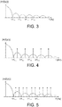
- T exp With a fixed exposure time T exp the acquisition process of the image capturing unit 5 produces a low pass filtering effect on the acquired light signal whereby the cut-off frequency (in Hertz) of the low pass filter is determined by the shutter speed value T exp (in seconds).
- Fig. 3 schematically illustrates the low-pass filter characteristic
- the image capturing unit 5 may further be arranged to capture images at one of a plurality of different exposure index ratings, or ISO values.
- the image capturing unit 5 may thus be able to receive and detect light, particularly coded light, at one or more of the plurality of different exposure index ratings.
- the image capturing unit 5 may further be arranged to capture images within a field of view 10a-10b along a general light detection direction.
- the image capturing unit 5 is thus able to receive and detect light, particularly coded light, within the field of view 10a-10b.
- the general light detection direction can be changed by changing the direction of the image capturing unit 5.
- the field of view 10a-10b may be narrowed by the remote control unit 4 performing a zoom-in operation.
- the field of view 10a-10b may be widened by the remote control unit 4 performing a zoom-out operation.
- the image capturing unit 5 is enabled to capture images in a plurality of different directions and with a plurality of different fields of view.
- Other parameters and settings of the image capturing unit 5 may comprise noise reduction, white balance, contrast, gamma value, focus point, and resolution (in video/image mode, which often may affect line rate and maximum frame rate).
- one or more of the parameters and settings of the image capturing unit 5, for example the exposure time or the exposure index rating is/are frozen just before the detection takes place (i.e. before the one or more images are captured).
- the parameters and settings are set on the basis of the current illumination conditions. Additionally, in order to have a reliable detection of coded light, it is necessary that the signals used by the lighting devices 2a, 2b, 2c for visible light communications, for example, are not a multiple of the exposure time, else the image capturing unit 5 is "blind" to it.
- the exposure time is automatically set (inter alia depending on the illumination conditions) or manually set every time a new image is to be captured, it can happen that the exposure time becomes a multiple of the time period of the signals sent by the lighting devices 2a, 2b, 2c. Information regarding the parameters and settings of the image capturing unit 5 is therefore communicated to the processing unit 6.
- the image capturing unit 5 of the remote control unit 4 detects the light emitted by the one or more lighting devices 2a-2c (the light being within the field of view 10a-10b of the image capturing unit 5).
- the settings of the image capturing unit 5 may thereby be utilized by the remote control unit 4 so that visible light communications received by the image capturing unit 5 can be adapted to the settings.
- the remote control unit 4 further comprises a processing unit 6.
- the processing unit 6 may be implemented by a so-called central processing unit (CPU).
- CPU central processing unit
- the processing unit 6 determines one or more properties of the signals for visible light communications (VLC) to be used by the one or more lighting devices 2a, 2b, 2c based on the current settings of the image capturing unit 5.
- the one or more properties are thus based on one or more of the current exposure time, exposure index rating, noise reduction, white balance, contrast, gamma value, focus point, and resolution of the image capturing unit 5.
- the one or more properties are determined such that the signals for visible light communications may be detected by the image capturing unit 5.
- the current settings thus relate a current exposure index rating of the image capturing unit 5.
- the properties preferably relate to a power level to be used by the set of lighting devices 2a, 2b, 2c during visible light communications.
- the current settings thus relate to a current exposure time indication of the image capturing unit 5.
- the signals for visible light communications are thus based on the current exposure time of the image capturing unit 5.
- Properties of the signals for visible light communications are preferably determined such that the main frequency characteristics of the signals for visible light communications do not correspond to the blind spots (i.e. the zero crossings) of the frequency representation of the current exposure time of the image capturing unit 5 (due to the low-pass filter effect as disclosed above).
- Figs. 4 and 5 illustrate examples of possible signal allocations as spikes " ⁇ " along with the low-pass filter characteristic
- the processing unit 6 may be arranged to determine the main frequency to be inside the main lobe or a side lobe of a frequency representation of the exposure time indication.
- the main frequency is determined to be inside a side lobe
- the frequency is preferably a midpoint of the side lobe (as in Fig. 4 ). This would maximize the distance of the frequency to the zero crossings of the low-pass-filter. This would also minimize the attenuation due to the low pass filter.
- the main frequency characteristics is determined to be inside a side lobe the side lobe is preferably the first side lobe (i.e. the side lobe neighboring the main lobe).
- the frequency characteristics are generally determined to be within a predetermined frequency range, thereby restricting the bandwidth of the signals for visible light communications. Restricting the lower end point of the bandwidth of the signals for visible light communications to be higher than a certain frequency may be beneficial in order to avoid flicker in the visible light. Restricting the upper end point of the bandwidth of the signals for visible light communications to be lower than a certain frequency may be beneficial in order to keep the signals away from regions in the frequency representation where the low-pass filter attenuation is too severe for practical situations.
- the signals for visible light communications may be based on coding techniques whereby the waveform representing the signal is modulated according to a digital information sequence.
- each individual lighting device 2a, 2b, 2c is associated with its own unique information sequence.
- the unique information sequence may thus represent a lighting device identification code.
- the identification code may be realized as a pulse width modulation code.
- the identification code may be realized by using code division multiple access techniques. It is to be understood that other embodiments for the realization of identification codes are known to a person skilled in the art.
- the resulting spectrum of the modulated sequence of waveforms can be derived from the basic waveform function and the characteristics of the digital information sequence.
- the power spectrum of a modulated waveforms based on linear pulse amplitude modulation may be regarded as the multiplication of the power spectrum of the discrete digital information sequence and the absolute square of the Fourier spectrum of the basic pulse function.
- digital information sequences with different spectral characteristics may be applied in order to shape the spectrum of the basic pulse function into certain desirable shapes.
- the encoding mechanisms may therefore be referred to as spectrum shaping codes.
- a desirable signal spectrum may be based on any one of the above disclosed parameters and settings of the image capturing unit 5. Coding techniques may then be applied to shape the modulated signal waveform into the desirable spectrum.
- a number of non-limiting examples of spectrum shaping codes will be presented next.
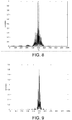
- the spectra presented here are numerically computed based on a 500 Hz on-off sequence within a 1 second time interval.
- the basic modulation waveform is illustrated in Fig. 6 .
- the spectrum from a random sequence without any spectrum shaping code is schematically illustrated in Fig. 7 .
- a repetition code with length 4 is applied as an example of a spectrum shaping code, i.e. the source information bit 1 is mapped to the channel code sequence 1111, and the source information bit 0 is mapped to the channel code sequence 0000.
- the spectrum of the modulated waveform is schematically illustrated in Fig. 8 .
- a repetition code with length 10 is applied as the spectrum shaping code, i.e. bit 1 is now 1111111111 and bit 0 is now 0000000000.
- the spectrum is schematically illustrated in Fig. 9 .
- the spectrum with spectrum shaping code is much more narrow than that without the spectrum shaping code.
- the spectrum of the repetition code of length 10 is more narrow than that with repetition code of length 4.
- the achievable data rate with repetition code length 10 is generally lower than that with repetition code length 4.
- the appropriate center frequency and the appropriate length for the repetition code may be dictated by practical circumstances and conditions of the lighting system 1 under consideration.
- the width of the signal spectrum may be tuned to generate the signal with a spectrum suitable for the current values of the parameters and settings of the image capturing unit, thereby enabling detection of the coded light.
- the criteria for selecting the signals may depend on the number of lighting devices in the set of lighting devices 2a, 2b, 2c (hence number of required signals), on the channel condition (e.g. the distance and/or illumination conditions between the lighting devices 2a, 2b, 2c and the remote control unit), etc.
- the signals are preferably chosen such that the signals are maximally spaced (in frequency sense) in relation to each other to reduce the risk of cross-talk.
- the remote control unit 4 further comprises a transmitter 7.
- the transmitter 7 may be a light transmitter configured to emit coded light.
- the transmitter 7 may be a radio transmitter configured to wirelessly transmit information.
- the transmitter 7 may be configured for bidirectional communications.
- the transmitter 7 may comprise a radio antenna.
- the transmitter 7 may comprise a connector for wired communications.
- the transmitter 7 thus transmits a control signal pertaining to the determined properties of the signals for visible light communications to the set of lighting devices 2a, 2b, 2c.
- Fig. 2 illustrates a lighting device 2a, 2b, 2c according to embodiments.
- the receiver 12 is arranged to receive the control signal as generated by the remote control unit 4. Once a lighting device 2a, 2b, 2c has received the control signal the lighting device 2a, 2b, 2c may produce output light using the assigned signal.
- the lighting device 2a, 2b, 2c therefore comprises a light driver 13 which is arranged to generate a light emitting control signal based on the control signal.
- the light emitter 14 of the lighting device 2a, 2b, 2c may then emit visible light communications signals based on the light emitting control signal.
- the processing unit 6 of the remote control unit 4 is therefore preferably arranged to fix the settings and parameters of the image capturing unit 5 in accordance with the properties enclosed in the control signal transmitted to the lighting devices 2a, 2b, 2c.
- the processing unit 6 may fix the exposure time and/or exposure index rating of the image capturing unit 5 based on the exposure time indication and/or the exposure index rating.
- the image capturing unit 5 may then receive VLC signals having the one or more properties from at least one of the set of lighting devices 2a, 2b, 2c at the fixed exposure time and/or exposure index rating.
- the remote control unit 4 may thereby be arranged to identify an individual lighting device 2a, 2b, 2c from the set of lighting devices 2a, 2b, 2c.
- the individual lighting device 2a-2c are preferably identified by lighting device identification codes, which, as discussed above, may be embedded in the emitted light contributions of the lighting device 2a, 2b, 2c.
- the remote control unit 4 may further comprise a user interface 11 through which a user is enabled to interact with the functionality of the remote control unit 4.
- the user interface 11 may in particular be arranged to receive user input and to provide information to the user.
- the user input may receive tactile user input for example from a keyboard or a joystick provided on, or being operatively coupled to, the remote control unit 4.
- a keyboard or a joystick provided on, or being operatively coupled to, the remote control unit 4.
- the remote control unit 4 may further comprise other components, such as a memory 9 operatively coupled to the processing unit 6.
- the memory 9 is operated according to principles which as such are known by the skilled person.
- the memory 9 may comprise a set of control signals pertaining to the properties of the signals for visible light communications to be transmitted to the set of lighting devices 2a, 2b, 2c.
- the disclosed remote control unit 4 and at least one luminaire comprising at least one lighting device 2a, 2b, 2c and being controllable by the remote control unit 4 may be provided as an arrangement.
- the invention is not limited to control of the lighting device by a remote control.
- any adaptation of the modulation frequency could also potentially avoid blind spots, e.g. by varying the frequency autonomously at the lighting device.
- the blind spots are not limited to those due to a rolling shutter acquisition process. It will be appreciated given the present disclosure that the adapting of the modulation can be used to avoid any frequency blind spot that may exist in the image capturing unit, e.g. due to some other side effect or limitation of the acquisition process such as some other filtering effect.
- a computer program may be stored/distributed on a suitable medium, such as an optical storage medium or a solid-state medium supplied together with or as part of other hardware, but may also be distributed in other forms, such as via the Internet or other wired or wireless telecommunication systems. Any reference signs in the claims should not be construed as limiting the scope.
Claims (16)
- Fernbedienungseinheit (4) zum Steuern eines Satzes von Beleuchtungsvorrichtungen (2a, 2b, 2c), umfassend:- eine Verarbeitungseinheit (6), die dazu eingerichtet ist, eine oder mehrere Signaleigenschaften für Kommunikationen mit sichtbarem Licht zu bestimmen; und- einen Sender (7), der dazu eingerichtet ist, ein Steuersignal in Zusammenhang mit den Eigenschaften an den Satz von Beleuchtungsvorrichtungen zu senden, dadurch gekennzeichnet, dass die Bestimmung von einer oder mehreren Signaleigenschaften für Kommunikationen mit sichtbarem Licht auf aktuellen Einstellungen einer Bilderfassungseinheit basiert.
- Fernbedienungseinheit nach Anspruch 1, wobei sich die aktuellen Einstellungen auf einen aktuellen Nennbelichtungsindex der Bilderfassungseinheit beziehen und wobei sich die Eigenschaften auf einen Leistungspegel beziehen, der von dem Satz von Beleuchtungsvorrichtungen verwendet werden soll.
- Fernbedienungseinheit nach Anspruch 1, wobei sich die aktuellen Eistellungen auf eine aktuelle Belichtungszeitangabe der Bilderfassungseinheit beziehen und wobei sich die Eigenschafen auf Frequenzcharakteristiken der Signale für Kommunikationen mit sichtbarem Licht, das von den Beleuchtungsvorrichtungen emittiert wird, beziehen.
- Fernbedienungseinheit nach Anspruch 2 oder 3, weiter umfassend:- die Bilderfassungseinheit, die dazu fähig ist, bei einer Vielzahl von Einstellungen Bilder zu erfassen, wobei die aktuellen Einstellungen aus der Vielzahl von Einstellungen ausgewählt werden.
- Fernbedienungseinheit nach Anspruch 4, wobei
die Verarbeitungseinheit dazu eingerichtet ist, die Belichtungszeit und/oder den Nennbelichtungsindex der Bilderfassungseinheit basierend auf der Belichtungszeitangabe und/oder dem Nennbelichtungsindex festzulegen, und
wobei die Bilderfassungseinheit dazu eingerichtet ist, Signale für Kommunikationen mit sichtbarem Licht zu empfangen, die die eine oder mehrere Eigenschaften von mindestens einer aus dem Satz von Beleuchtungsvorrichtungen auf der festgelegten Belichtungszeit und/oder dem Nennbelichtungsindex besitzen. - Fernbedienungseinheit nach Anspruch 3, wobei sich die Eigenschaften auf eine Hauptfrequenzcharakteristiken der Signale beziehen, und wobei die Verarbeitungseinheit (6) dazu eingerichtet ist, die Hauptfrequenzcharakteristiken so zu bestimmen, dass sie innerhalb der Hauptkeule oder einer Nebenkeule einer Frequenzdarstellung der Belichtungszeitangabe liegen.
- Fernbedienungseinheit nach Anspruch 6, wobei die Verarbeitungseinheit (6) dazu eingerichtet ist, die Frequenzcharakteristiken so zu bestimmen, dass sie innerhalb eines vorbestimmten Frequenzbereichs liegen.
- Fernbedienungseinheit nach einem der vorhergehenden Ansprüche, wobei die Verarbeitungseinheit (6) dazu eingerichtet ist, die Signale für Kommunikationen mit sichtbarem Licht so zu bestimmen, dass sie eines aus Amplitudenmodulation, Frequenzmodulation, und Phasenmodulation nutzen.
- Fernbedienungseinheit nach einem der Ansprüche 6 bis 8, wobei die Verarbeitungseinheit (6) dazu eingerichtet ist, die Signale für Kommunikationen mit sichtbarem Licht durch Formen des Spektrums der Signale zu bestimmen.
- Fernbedienungseinheit nach einem der vorhergehenden Ansprüche, wobei die aktuellen Einstellungen einen Teilsatz von Signalen aus einem Satz von vorbestimmten Signalen identifizieren.
- System, umfassend eine Fernbedienungseinheit (4) und mindestens eine Beleuchtungsvorrichtung (2a, 2b, 2c), wobei die Fernbedienungseinheit dazu eingerichtet ist, die Beleuchtungsvorrichtung (2a, 2b, 2c) zu steuern,
wobei die Fernbedienungseinheit umfasst:- eine Verarbeitungseinheit (6), die dazu eingerichtet ist, eine oder mehrere Signaleigenschaften für Kommunikationen mit sichtbarem Licht zu bestimmen; und- einen Sender (7), der dazu eingerichtet ist, ein Steuersignal in Zusammenhang mit den Eigenschaften an den Satz von Beleuchtungsvorrichtungen zu senden; undwobei die mindestens eine Beleuchtungsvorrichtung umfasst:- einen Empfänger (12), der dazu eingerichtet ist, das Steuersignal zu empfangen;- einen Lichttreiber (13), der dazu eingerichtet ist, ein Lichtemissions-Steuersignal basierend auf dem Steuersignal zu generieren, und- einen Lichtemitter (14), der dazu eingerichtet ist, Kommunikationen mit sichtbarem Licht basierend auf dem Lichtemissions-Steuersignal zu emittieren, dadurch gekennzeichnet, dass die Bestimmung von einer oder mehreren Signaleigenschaften für Kommunikationen mit sichtbarem Licht auf aktuellen Einstellungen einer Bilderfassungseinheit basiert. - Verfahren zum Steuern eines Satzes von Beleuchtungsvorrichtungen (2a, 2b, 2c), umfassend:Bestimmen (S2), durch eine Verarbeitungseinheit (6), von einer oder mehreren Signaleigenschaften für Kommunikationen mit sichtbarem Licht; undSenden (S4), durch einen Sender (7), eines Steuersignals in Zusammenhang mit den Eigenschaften an den Satz von Beleuchtungsvorrichtungen, dadurch gekennzeichnet, dass die Bestimmung von einer oder mehreren Signaleigenschaften für Kommunikationen mit sichtbarem Licht auf aktuellen Einstellungen einer Bilderfassungseinheit basiert.
- Beleuchtungsvorrichtung, umfassend:einen Lichtemitter (14), der dazu eingerichtet ist, einen sichtbaren Lichtausgang, der moduliert wird, auf einer Hauptmodulationsfrequenz zu emittieren, um Daten zur Erkennung durch eine Bilderfassungseinheit in den Lichtausgang einzubetten; gekennzeichnet durcheinen Lichttreiber (13), der dazu eingerichtet ist, die Modulationsfrequenz so anzupassen, dass sie keinen blinken Flecken entspricht, die durch einen Aufnahmevorgang der Bilderfassungseinheit erzeugt werden.
- Beleuchtungsvorrichtung nach Anspruch 13, wobei der Lichttreiber (13) dazu eingerichtet ist, die Modulationsfrequenz so anzupassen, dass sie keinen blinden Flecken entspricht, die durch einen Tiefpassfiltereffekt bedingt sind, der durch den Aufnahmevorgang der Bilderfassungseinheit erzeugt wird.
- Beleuchtungsvorrichtung nach Anspruch 13 oder 14, wobei der Lichttreiber (13) dazu eingerichtet ist, die Modulationsfrequenz so anzupassen, dass sie keinen blinden Flecken entspricht, die durch eine Belichtungszeit oder einen Nennbelichtungsindex des Aufnahmevorgangs erzeugt werden.
- Beleuchtungsvorrichtung nach einem der Ansprüche 13 bis 15, umfassend einen Empfänger (12), der dazu eingerichtet ist, ein Steuersignal von einer Fernbedienungseinheit zu empfangen, wobei der Lichttreiber (13) dazu eingerichtet ist, das Anpassen der Modulationsfrequenz auf dem Steuersignal basierend durchzuführen.
Applications Claiming Priority (3)
| Application Number | Priority Date | Filing Date | Title |
|---|---|---|---|
| US201261587298P | 2012-01-17 | 2012-01-17 | |
| US201261599459P | 2012-02-16 | 2012-02-16 | |
| PCT/IB2013/050324 WO2013108166A1 (en) | 2012-01-17 | 2013-01-14 | Visible light communications using a remote control |
Publications (2)
| Publication Number | Publication Date |
|---|---|
| EP2805586A1 EP2805586A1 (de) | 2014-11-26 |
| EP2805586B1 true EP2805586B1 (de) | 2017-12-13 |
Family
ID=47827391
Family Applications (2)
| Application Number | Title | Priority Date | Filing Date |
|---|---|---|---|
| EP13707711.1A Active EP2805586B1 (de) | 2012-01-17 | 2013-01-14 | Kommunikation mit sichtbarem licht unter verwendung einer fernbedienung |
| EP13707712.9A Active EP2805587B1 (de) | 2012-01-17 | 2013-01-14 | Modulation der lichtstrahlung einer beleuchtungsvorrichtung mit mehreren unterschiedlichen modulationsperioden |
Family Applications After (1)
| Application Number | Title | Priority Date | Filing Date |
|---|---|---|---|
| EP13707712.9A Active EP2805587B1 (de) | 2012-01-17 | 2013-01-14 | Modulation der lichtstrahlung einer beleuchtungsvorrichtung mit mehreren unterschiedlichen modulationsperioden |
Country Status (7)
| Country | Link |
|---|---|
| US (2) | US9386643B2 (de) |
| EP (2) | EP2805586B1 (de) |
| JP (2) | JP6125535B2 (de) |
| CN (2) | CN104041191B (de) |
| ES (1) | ES2659037T3 (de) |
| RU (1) | RU2628570C2 (de) |
| WO (2) | WO2013108167A1 (de) |
Families Citing this family (71)
| Publication number | Priority date | Publication date | Assignee | Title |
|---|---|---|---|---|
| CN103365032B (zh) * | 2012-03-28 | 2017-06-06 | 鸿富锦精密工业(深圳)有限公司 | 光源通道校正方法及系统 |
| US9374875B2 (en) * | 2012-09-12 | 2016-06-21 | Ariel-University Research And Development Company Ltd. | Light fixture connectable device useful for establishing a network infrastructure |
| DE102013014536B4 (de) | 2013-09-03 | 2015-07-09 | Sew-Eurodrive Gmbh & Co Kg | Verfahren zur Übertragung von Information und Vorrichtung zur Durchführung des Verfahrens |
| WO2015039037A2 (en) * | 2013-09-13 | 2015-03-19 | Cooper Technologies Company | Artificial light source based messaging platform |
| ITTO20130818A1 (it) * | 2013-10-10 | 2015-04-11 | Neodelis S R L | Dispositivo di illuminazione intelligente, e relativi metodo e sistema |
| WO2015059608A1 (en) * | 2013-10-24 | 2015-04-30 | Koninklijke Philips N.V. | Attachable lighting control apparatus |
| US9419716B2 (en) * | 2013-11-14 | 2016-08-16 | Nicolas Thomas Mathieu Dupont | Variable color data transmission |
| US10028277B2 (en) | 2013-11-20 | 2018-07-17 | Cyborg Inc. | Variable frequency data transmission |
| US10237953B2 (en) | 2014-03-25 | 2019-03-19 | Osram Sylvania Inc. | Identifying and controlling light-based communication (LCom)-enabled luminaires |
| CN106576412A (zh) * | 2014-05-12 | 2017-04-19 | 飞利浦灯具控股公司 | 编码光的检测 |
| JP6545192B2 (ja) * | 2014-05-12 | 2019-07-17 | シグニファイ ホールディング ビー ヴィ | 変調光源からの照光から復号されたタイムスタンプを使用する、捕捉された画像の検証 |
| US9648452B1 (en) | 2014-06-05 | 2017-05-09 | ProSports Technologies, LLC | Wireless communication driven by object tracking |
| US10592924B1 (en) | 2014-06-05 | 2020-03-17 | ProSports Technologies, LLC | Managing third party interactions with venue communications |
| US10290067B1 (en) | 2014-06-05 | 2019-05-14 | ProSports Technologies, LLC | Wireless concession delivery |
| US9711146B1 (en) | 2014-06-05 | 2017-07-18 | ProSports Technologies, LLC | Wireless system for social media management |
| US9635506B1 (en) | 2014-06-05 | 2017-04-25 | ProSports Technologies, LLC | Zone based wireless player communications |
| US10009100B2 (en) * | 2014-06-18 | 2018-06-26 | Qualcomm Incorporated | Transmission of identifiers using visible light communication |
| NL1040869B1 (en) * | 2014-06-27 | 2016-06-08 | Eldolab Holding Bv | A method for driving a light source, a driver system to drive a light source and a luminaire comprising said light source and driver system. |
| CN104092953B (zh) | 2014-07-10 | 2018-09-04 | 北京智谷睿拓技术服务有限公司 | 调光控制方法和装置及具有拍照功能的设备 |
| US9724588B1 (en) | 2014-07-11 | 2017-08-08 | ProSports Technologies, LLC | Player hit system |
| US9305441B1 (en) | 2014-07-11 | 2016-04-05 | ProSports Technologies, LLC | Sensor experience shirt |
| US9760572B1 (en) | 2014-07-11 | 2017-09-12 | ProSports Technologies, LLC | Event-based content collection for network-based distribution |
| WO2016007970A1 (en) | 2014-07-11 | 2016-01-14 | ProSports Technologies, LLC | Whistle play stopper |
| US9474933B1 (en) | 2014-07-11 | 2016-10-25 | ProSports Technologies, LLC | Professional workout simulator |
| WO2016007962A1 (en) | 2014-07-11 | 2016-01-14 | ProSports Technologies, LLC | Camera feed distribution from event venue virtual seat cameras |
| US9398213B1 (en) | 2014-07-11 | 2016-07-19 | ProSports Technologies, LLC | Smart field goal detector |
| US9965938B1 (en) | 2014-07-11 | 2018-05-08 | ProSports Technologies, LLC | Restroom queue management |
| WO2016007965A1 (en) | 2014-07-11 | 2016-01-14 | ProSports Technologies, LLC | Ball tracker camera |
| WO2016007972A1 (en) | 2014-07-11 | 2016-01-14 | ProSports Technologies, LLC | Ticket upsell system |
| US9571903B2 (en) | 2014-07-11 | 2017-02-14 | ProSports Technologies, LLC | Ball tracker snippets |
| US9610491B2 (en) | 2014-07-11 | 2017-04-04 | ProSports Technologies, LLC | Playbook processor |
| US9655027B1 (en) | 2014-07-11 | 2017-05-16 | ProSports Technologies, LLC | Event data transmission to eventgoer devices |
| US9343066B1 (en) | 2014-07-11 | 2016-05-17 | ProSports Technologies, LLC | Social network system |
| US9892371B1 (en) | 2014-07-28 | 2018-02-13 | ProSports Technologies, LLC | Queue information transmission |
| US9729644B1 (en) | 2014-07-28 | 2017-08-08 | ProSports Technologies, LLC | Event and fantasy league data transmission to eventgoer devices |
| JP6588530B2 (ja) | 2014-08-05 | 2019-10-09 | シグニファイ ホールディング ビー ヴィ | 複数システムの制御可能装置のコンテキスト適応制御 |
| US9607497B1 (en) | 2014-08-25 | 2017-03-28 | ProSports Technologies, LLC | Wireless communication security system |
| WO2016032714A1 (en) | 2014-08-25 | 2016-03-03 | ProSports Technologies, LLC | Disposable connectable wireless communication receiver |
| US9699523B1 (en) | 2014-09-08 | 2017-07-04 | ProSports Technologies, LLC | Automated clip creation |
| US10264175B2 (en) | 2014-09-09 | 2019-04-16 | ProSports Technologies, LLC | Facial recognition for event venue cameras |
| WO2016039987A1 (en) | 2014-09-11 | 2016-03-17 | ProSports Technologies, LLC | System to offer coupons to fans along routes to game |
| US10085329B2 (en) | 2014-10-09 | 2018-09-25 | Philips Lighting Holding B.V. | Optically powered lighting system |
| CN104363054B (zh) * | 2014-10-30 | 2017-07-21 | 北京智谷睿拓技术服务有限公司 | 可见光信号发射控制方法、控制装置、发射设备及移动设备 |
| EP3216320B1 (de) * | 2014-11-04 | 2018-04-04 | Philips Lighting Holding B.V. | Sender mit einer sendewarteschlange und zugehörige quellenvorrichtung |
| WO2016133285A1 (ko) * | 2015-02-17 | 2016-08-25 | 국민대학교산학협력단 | 롤링 셔터 변조를 이용한 이미지 센서 통신 시스템 및 통신 방법 |
| US10560188B2 (en) | 2015-02-17 | 2020-02-11 | Kookmin University Industry Academy Cooperation Foundation | Image sensor communication system and communication method using rolling shutter modulation |
| US9930741B2 (en) * | 2015-02-27 | 2018-03-27 | Xicato, Inc. | Synchronized light control over a wireless network |
| WO2016149570A1 (en) * | 2015-03-19 | 2016-09-22 | University Of Delaware | Spectral imaging sensors and methods with time of flight seneing |
| JP6704935B2 (ja) * | 2015-04-22 | 2020-06-03 | シグニファイ ホールディング ビー ヴィSignify Holding B.V. | 照明配置図作成器 |
| CN105072752B (zh) * | 2015-07-31 | 2018-11-23 | 广州飞达音响股份有限公司 | 一种音响的灯光调节方法、装置以及系统 |
| US9742493B2 (en) * | 2015-09-30 | 2017-08-22 | Osram Sylvania Inc. | Reconstructing light-based communication signals captured with a rolling shutter image capture device |
| EP3779274A1 (de) | 2015-10-02 | 2021-02-17 | PCMS Holdings, Inc. | Digitales lampenschirmsystem und verfahren |
| CN107113058B (zh) * | 2015-11-06 | 2020-12-18 | 松下电器(美国)知识产权公司 | 可见光信号的生成方法、信号生成装置以及介质 |
| US20170139582A1 (en) * | 2015-11-13 | 2017-05-18 | General Electric Company | Method and system for controlling an illumination device and related lighting system |
| TWI576007B (zh) * | 2015-11-23 | 2017-03-21 | 財團法人工業技術研究院 | 發光裝置的驅動方法與發光裝置 |
| US10531538B2 (en) | 2016-02-08 | 2020-01-07 | Beghelli S.P.A. | Apparatus and method for remote control of lighting equipments |
| ITUB20160571A1 (it) * | 2016-02-08 | 2017-08-08 | Beghelli Spa | Apparato e metodo per il controllo a distanza di apparecchi di illuminazione |
| US9893808B2 (en) | 2016-03-18 | 2018-02-13 | Target Brands, Inc. | VLC location data applications in a retail setting |
| TWI616071B (zh) * | 2016-04-08 | 2018-02-21 | 凌通科技股份有限公司 | 應用於可見光的可調光與光通訊之發光裝置與互動裝置 |
| US10637575B2 (en) * | 2016-05-25 | 2020-04-28 | Wisconsin Alumni Research Foundation | Spatial location indoors using standard fluorescent fixtures |
| US10132687B2 (en) | 2016-06-30 | 2018-11-20 | Gooee Limited | Three-dimensional VLC/DLC sensor clip |
| NL2017308B1 (en) * | 2016-08-11 | 2018-02-16 | Eldolab Holding Bv | Method of light unit replacement |
| TWI610540B (zh) * | 2016-12-06 | 2018-01-01 | 財團法人工業技術研究院 | 可見光通訊裝置、方法及系統 |
| CN110268644A (zh) * | 2017-02-16 | 2019-09-20 | 昕诺飞控股有限公司 | 用于与照明设备进行光通信的系统 |
| US10122455B1 (en) * | 2017-05-01 | 2018-11-06 | Gooee Limited | VLC/DLC Sectorized communication |
| US10987071B2 (en) * | 2017-06-29 | 2021-04-27 | University Of Delaware | Pixelated K-edge coded aperture system for compressive spectral X-ray imaging |
| CN110072065B (zh) * | 2018-01-23 | 2021-04-27 | 舜宇光学(浙江)研究院有限公司 | 适用于卷帘曝光深度相机的投射器工作时间控制方法及其应用 |
| CN111656766B (zh) * | 2018-01-29 | 2022-10-28 | 昕诺飞控股有限公司 | 用于基于图像的服务的设备 |
| FR3079205B1 (fr) * | 2018-03-26 | 2022-01-28 | Seilliere Jean Baptiste | Masque de plongee comprenant un module de communication lifi |
| US11019276B1 (en) * | 2019-11-14 | 2021-05-25 | Hand Held Products, Inc. | Apparatuses and methodologies for flicker control |
| CN112672462B (zh) * | 2020-12-11 | 2024-04-02 | 光华临港工程应用技术研发(上海)有限公司 | 一种照明调节装置及照明系统 |
Family Cites Families (34)
| Publication number | Priority date | Publication date | Assignee | Title |
|---|---|---|---|---|
| US6198230B1 (en) | 1998-04-15 | 2001-03-06 | Talking Lights | Dual-use electronic transceiver set for wireless data networks |
| US6528182B1 (en) | 1998-09-15 | 2003-03-04 | Sollac | Zinc coated steel plates coated with a pre-lubricating hydroxysulphate layer and methods for obtaining same |
| FR2791007B1 (fr) | 1999-03-16 | 2001-05-25 | France Design | Toit repliable pour vehicule decouvrable |
| EP1858179A1 (de) * | 2002-10-24 | 2007-11-21 | Nakagawa Laboratories, Inc. | Beleutungsvorrichtung zur Datenübertragung |
| JP3827082B2 (ja) * | 2002-10-24 | 2006-09-27 | 株式会社中川研究所 | 放送システム及び電球、照明装置 |
| KR100551237B1 (ko) * | 2003-06-18 | 2006-02-09 | (주)세고엔터테인먼트 | 휴대용 통신단말기의 디스플레이부의 점멸간격을 이용한 통신 장치 및 방법 |
| JP2005218067A (ja) * | 2004-02-02 | 2005-08-11 | Nakagawa Kenkyusho:Kk | 可視光通信用のカメラ付き携帯端末 |
| JP2006010745A (ja) * | 2004-06-22 | 2006-01-12 | Sony Corp | 照明装置 |
| JP4797415B2 (ja) * | 2005-03-25 | 2011-10-19 | 株式会社ニコン | 照明装置、撮影装置および撮影システム |
| EP1882394B1 (de) * | 2005-04-22 | 2018-09-19 | Philips Lighting Holding B.V. | Beleuchtungssteuersystem |
| EP1989925A1 (de) * | 2006-02-23 | 2008-11-12 | TIR Technology LP | System und verfahren zur lichtquellenidentifikation |
| KR101345357B1 (ko) * | 2006-03-02 | 2013-12-30 | 코닌클리케 필립스 엔.브이. | 조명 장치 |
| US7667740B2 (en) | 2006-07-28 | 2010-02-23 | Hewlett-Packard Development Company, L.P. | Elimination of modulated light effects in rolling shutter CMOS sensor images |
| BRPI0718153A2 (pt) | 2006-10-27 | 2013-11-05 | Koninkl Philips Electronics Nv | Fonte de luz de cor controlada e método para controlar a geração de cor em uma fonte de lu |
| WO2008050293A1 (en) | 2006-10-27 | 2008-05-02 | Koninklijke Philips Electronics N.V. | A color controlled light source and a method for controlling color generation in a light source |
| US8264168B2 (en) * | 2007-05-09 | 2012-09-11 | Koninklijke Philips Electronics N.V. | Method and a system for controlling a lighting system |
| ATE490674T1 (de) * | 2007-07-18 | 2010-12-15 | Koninkl Philips Electronics Nv | Verfahren zur verarbeitung von licht in einer struktur und beleuchtungssystem |
| CN101184355B (zh) * | 2007-12-06 | 2011-03-16 | 哈尔滨师范大学 | 三基色led光源合成白光的方法 |
| WO2009090511A2 (en) * | 2008-01-17 | 2009-07-23 | Koninklijke Philips Electronics N.V. | Method and apparatus for light intensity control |
| EP2088836A1 (de) | 2008-01-31 | 2009-08-12 | Ledon Lighting Jennersdorf GmbH | LED-Beleuchtungssystem mit optischer Kommunikationsfunktion |
| WO2009101570A1 (en) * | 2008-02-12 | 2009-08-20 | Koninklijke Philips Electronics N.V. | Adaptive modulation and data embedding in light for advanced lighting control |
| JP5374202B2 (ja) * | 2008-03-28 | 2013-12-25 | 株式会社プランナーズランド | 可視光通信装置 |
| RU2538102C2 (ru) * | 2009-04-08 | 2015-01-10 | Конинклейке Филипс Электроникс Н.В. | Эффективное назначение адресов в системах кодированного освещения |
| TW201043088A (en) | 2009-05-20 | 2010-12-01 | Pixart Imaging Inc | Light control system and control method thereof |
| WO2011001392A2 (en) | 2009-07-03 | 2011-01-06 | Koninklijke Philips Electronics N.V. | Method and system for asynchronous lamp identification |
| BR112012001312B1 (pt) * | 2009-07-24 | 2021-02-02 | Philips Lighting Holding B.V. | sistema de iluminação |
| CA2772009A1 (en) * | 2009-08-27 | 2011-03-03 | Koninklijke Philips Electronics N.V. | Cognitive identifier assignment for light source control |
| CN102612809B (zh) * | 2009-10-28 | 2015-12-02 | 皇家飞利浦电子股份有限公司 | 启用编码光源 |
| US8942570B2 (en) * | 2010-01-15 | 2015-01-27 | Koninklijke Phillips N.V. | Data detection for visible light communications using conventional camera sensor |
| EP2503852A1 (de) | 2011-03-22 | 2012-09-26 | Koninklijke Philips Electronics N.V. | Lichterkennungssystem und -verfahren |
| US9287976B2 (en) * | 2011-07-26 | 2016-03-15 | Abl Ip Holding Llc | Independent beacon based light position system |
| US8749146B2 (en) * | 2011-12-05 | 2014-06-10 | Mojo Labs, Inc. | Auto commissioning of light fixture using optical bursts |
| US8749145B2 (en) * | 2011-12-05 | 2014-06-10 | Mojo Labs, Inc. | Determination of lighting contributions for light fixtures using optical bursts |
| US8699887B1 (en) * | 2013-03-14 | 2014-04-15 | Bret Rothenberg | Methods and systems for encoding and decoding visible light with data and illumination capability |
-
2013
- 2013-01-14 EP EP13707711.1A patent/EP2805586B1/de active Active
- 2013-01-14 ES ES13707711.1T patent/ES2659037T3/es active Active
- 2013-01-14 EP EP13707712.9A patent/EP2805587B1/de active Active
- 2013-01-14 US US14/372,523 patent/US9386643B2/en active Active
- 2013-01-14 US US14/372,554 patent/US9363857B2/en active Active
- 2013-01-14 CN CN201380005817.1A patent/CN104041191B/zh active Active
- 2013-01-14 WO PCT/IB2013/050326 patent/WO2013108167A1/en active Application Filing
- 2013-01-14 RU RU2014133724A patent/RU2628570C2/ru active
- 2013-01-14 JP JP2014551716A patent/JP6125535B2/ja active Active
- 2013-01-14 JP JP2014551717A patent/JP6263130B2/ja active Active
- 2013-01-14 CN CN201380005765.8A patent/CN104041190B/zh active Active
- 2013-01-14 WO PCT/IB2013/050324 patent/WO2013108166A1/en active Application Filing
Also Published As
| Publication number | Publication date |
|---|---|
| ES2659037T3 (es) | 2018-03-13 |
| JP2015513806A (ja) | 2015-05-14 |
| CN104041190A (zh) | 2014-09-10 |
| JP6125535B2 (ja) | 2017-05-10 |
| WO2013108167A1 (en) | 2013-07-25 |
| JP6263130B2 (ja) | 2018-01-17 |
| CN104041191A (zh) | 2014-09-10 |
| US20140375217A1 (en) | 2014-12-25 |
| EP2805587B1 (de) | 2019-06-26 |
| CN104041191B (zh) | 2016-12-07 |
| RU2628570C2 (ru) | 2017-08-21 |
| US9386643B2 (en) | 2016-07-05 |
| US20150028763A1 (en) | 2015-01-29 |
| US9363857B2 (en) | 2016-06-07 |
| RU2014133724A (ru) | 2016-03-10 |
| EP2805586A1 (de) | 2014-11-26 |
| CN104041190B (zh) | 2017-01-18 |
| JP2015509324A (ja) | 2015-03-26 |
| EP2805587A1 (de) | 2014-11-26 |
| WO2013108166A1 (en) | 2013-07-25 |
Similar Documents
| Publication | Publication Date | Title |
|---|---|---|
| EP2805586B1 (de) | Kommunikation mit sichtbarem licht unter verwendung einer fernbedienung | |
| US11915581B2 (en) | Visible light communication system and method | |
| US9504126B2 (en) | Coded light detector | |
| EP2749141B1 (de) | Kodierte übertragung und kodierter empfang von licht zur erzeugung von lichtszenen | |
| CA2892923C (en) | Self-identifying one-way authentication method using optical signals | |
| CN105075151A (zh) | 用于功率有效联合调光和可见光通信的方法和设备 | |
| WO2016001972A1 (ja) | 送信装置、受信装置、通信システム、及び送信方法ならびに受信方法 | |
| JP2017518693A (ja) | 符号化された光の検出 | |
| US20180227052A1 (en) | Apparatus and method for registering visible light communication device and combining visible light communication signal and wireless communication signal | |
| WO2019010005A1 (en) | LIGHT-BASED COMMUNICATION USING LIGHT MODULATION BASED ON CAMERA FRAME FREQUENCY | |
| EP3004984B1 (de) | Detektion von kodiertem licht | |
| US20200073011A1 (en) | Indoor Human Detection and Motion Tracking Using Light Reflections | |
| WO2013126585A1 (en) | System and method of extending the communication range in a visible light communication system | |
| TM et al. | i TS ASAAAAS00L | |
| WO2020030463A1 (en) | Method and controller for reducing the energy consumption of a lighting system |
Legal Events
| Date | Code | Title | Description |
|---|---|---|---|
| PUAI | Public reference made under article 153(3) epc to a published international application that has entered the european phase |
Free format text: ORIGINAL CODE: 0009012 |
|
| 17P | Request for examination filed |
Effective date: 20140818 |
|
| AK | Designated contracting states |
Kind code of ref document: A1 Designated state(s): AL AT BE BG CH CY CZ DE DK EE ES FI FR GB GR HR HU IE IS IT LI LT LU LV MC MK MT NL NO PL PT RO RS SE SI SK SM TR |
|
| DAX | Request for extension of the european patent (deleted) | ||
| RAP1 | Party data changed (applicant data changed or rights of an application transferred) |
Owner name: PHILIPS LIGHTING HOLDING B.V. |
|
| RIC1 | Information provided on ipc code assigned before grant |
Ipc: H05B 37/02 20060101AFI20170314BHEP Ipc: H04B 10/116 20130101ALI20170314BHEP Ipc: H05B 33/08 20060101ALI20170314BHEP |
|
| GRAP | Despatch of communication of intention to grant a patent |
Free format text: ORIGINAL CODE: EPIDOSNIGR1 |
|
| INTG | Intention to grant announced |
Effective date: 20170703 |
|
| RIN1 | Information on inventor provided before grant (corrected) |
Inventor name: DE BRUIJN, FREDERIK, JAN Inventor name: FERI, LORENZO Inventor name: BAGGEN, CONSTANT, PAUL, MARIE, JOZEF Inventor name: NIJSSEN, STEPHANUS, JOSEPH, JOHANNES Inventor name: GRITTI, TOMMASO Inventor name: YANG, HONGMING Inventor name: RAJAGOPALAN, RUBEN |
|
| GRAS | Grant fee paid |
Free format text: ORIGINAL CODE: EPIDOSNIGR3 |
|
| GRAA | (expected) grant |
Free format text: ORIGINAL CODE: 0009210 |
|
| AK | Designated contracting states |
Kind code of ref document: B1 Designated state(s): AL AT BE BG CH CY CZ DE DK EE ES FI FR GB GR HR HU IE IS IT LI LT LU LV MC MK MT NL NO PL PT RO RS SE SI SK SM TR |
|
| REG | Reference to a national code |
Ref country code: GB Ref legal event code: FG4D |
|
| REG | Reference to a national code |
Ref country code: AT Ref legal event code: REF Ref document number: 955481 Country of ref document: AT Kind code of ref document: T Effective date: 20171215 Ref country code: CH Ref legal event code: EP |
|
| REG | Reference to a national code |
Ref country code: IE Ref legal event code: FG4D |
|
| REG | Reference to a national code |
Ref country code: DE Ref legal event code: R096 Ref document number: 602013030726 Country of ref document: DE |
|
| REG | Reference to a national code |
Ref country code: FR Ref legal event code: PLFP Year of fee payment: 6 |
|
| REG | Reference to a national code |
Ref country code: ES Ref legal event code: FG2A Ref document number: 2659037 Country of ref document: ES Kind code of ref document: T3 Effective date: 20180313 |
|
| REG | Reference to a national code |
Ref country code: NL Ref legal event code: FP |
|
| REG | Reference to a national code |
Ref country code: LT Ref legal event code: MG4D |
|
| PG25 | Lapsed in a contracting state [announced via postgrant information from national office to epo] |
Ref country code: SE Free format text: LAPSE BECAUSE OF FAILURE TO SUBMIT A TRANSLATION OF THE DESCRIPTION OR TO PAY THE FEE WITHIN THE PRESCRIBED TIME-LIMIT Effective date: 20171213 Ref country code: LT Free format text: LAPSE BECAUSE OF FAILURE TO SUBMIT A TRANSLATION OF THE DESCRIPTION OR TO PAY THE FEE WITHIN THE PRESCRIBED TIME-LIMIT Effective date: 20171213 Ref country code: FI Free format text: LAPSE BECAUSE OF FAILURE TO SUBMIT A TRANSLATION OF THE DESCRIPTION OR TO PAY THE FEE WITHIN THE PRESCRIBED TIME-LIMIT Effective date: 20171213 Ref country code: NO Free format text: LAPSE BECAUSE OF FAILURE TO SUBMIT A TRANSLATION OF THE DESCRIPTION OR TO PAY THE FEE WITHIN THE PRESCRIBED TIME-LIMIT Effective date: 20180313 |
|
| PG25 | Lapsed in a contracting state [announced via postgrant information from national office to epo] |
Ref country code: BG Free format text: LAPSE BECAUSE OF FAILURE TO SUBMIT A TRANSLATION OF THE DESCRIPTION OR TO PAY THE FEE WITHIN THE PRESCRIBED TIME-LIMIT Effective date: 20180313 Ref country code: LV Free format text: LAPSE BECAUSE OF FAILURE TO SUBMIT A TRANSLATION OF THE DESCRIPTION OR TO PAY THE FEE WITHIN THE PRESCRIBED TIME-LIMIT Effective date: 20171213 Ref country code: RS Free format text: LAPSE BECAUSE OF FAILURE TO SUBMIT A TRANSLATION OF THE DESCRIPTION OR TO PAY THE FEE WITHIN THE PRESCRIBED TIME-LIMIT Effective date: 20171213 Ref country code: HR Free format text: LAPSE BECAUSE OF FAILURE TO SUBMIT A TRANSLATION OF THE DESCRIPTION OR TO PAY THE FEE WITHIN THE PRESCRIBED TIME-LIMIT Effective date: 20171213 Ref country code: GR Free format text: LAPSE BECAUSE OF FAILURE TO SUBMIT A TRANSLATION OF THE DESCRIPTION OR TO PAY THE FEE WITHIN THE PRESCRIBED TIME-LIMIT Effective date: 20180314 |
|
| PG25 | Lapsed in a contracting state [announced via postgrant information from national office to epo] |
Ref country code: SK Free format text: LAPSE BECAUSE OF FAILURE TO SUBMIT A TRANSLATION OF THE DESCRIPTION OR TO PAY THE FEE WITHIN THE PRESCRIBED TIME-LIMIT Effective date: 20171213 Ref country code: CZ Free format text: LAPSE BECAUSE OF FAILURE TO SUBMIT A TRANSLATION OF THE DESCRIPTION OR TO PAY THE FEE WITHIN THE PRESCRIBED TIME-LIMIT Effective date: 20171213 Ref country code: CY Free format text: LAPSE BECAUSE OF FAILURE TO SUBMIT A TRANSLATION OF THE DESCRIPTION OR TO PAY THE FEE WITHIN THE PRESCRIBED TIME-LIMIT Effective date: 20171213 Ref country code: EE Free format text: LAPSE BECAUSE OF FAILURE TO SUBMIT A TRANSLATION OF THE DESCRIPTION OR TO PAY THE FEE WITHIN THE PRESCRIBED TIME-LIMIT Effective date: 20171213 |
|
| PG25 | Lapsed in a contracting state [announced via postgrant information from national office to epo] |
Ref country code: PL Free format text: LAPSE BECAUSE OF FAILURE TO SUBMIT A TRANSLATION OF THE DESCRIPTION OR TO PAY THE FEE WITHIN THE PRESCRIBED TIME-LIMIT Effective date: 20171213 Ref country code: IS Free format text: LAPSE BECAUSE OF FAILURE TO SUBMIT A TRANSLATION OF THE DESCRIPTION OR TO PAY THE FEE WITHIN THE PRESCRIBED TIME-LIMIT Effective date: 20180413 Ref country code: RO Free format text: LAPSE BECAUSE OF FAILURE TO SUBMIT A TRANSLATION OF THE DESCRIPTION OR TO PAY THE FEE WITHIN THE PRESCRIBED TIME-LIMIT Effective date: 20171213 Ref country code: SM Free format text: LAPSE BECAUSE OF FAILURE TO SUBMIT A TRANSLATION OF THE DESCRIPTION OR TO PAY THE FEE WITHIN THE PRESCRIBED TIME-LIMIT Effective date: 20171213 |
|
| REG | Reference to a national code |
Ref country code: CH Ref legal event code: PL |
|
| REG | Reference to a national code |
Ref country code: DE Ref legal event code: R097 Ref document number: 602013030726 Country of ref document: DE |
|
| PG25 | Lapsed in a contracting state [announced via postgrant information from national office to epo] |
Ref country code: MC Free format text: LAPSE BECAUSE OF FAILURE TO SUBMIT A TRANSLATION OF THE DESCRIPTION OR TO PAY THE FEE WITHIN THE PRESCRIBED TIME-LIMIT Effective date: 20171213 |
|
| PLBE | No opposition filed within time limit |
Free format text: ORIGINAL CODE: 0009261 |
|
| STAA | Information on the status of an ep patent application or granted ep patent |
Free format text: STATUS: NO OPPOSITION FILED WITHIN TIME LIMIT |
|
| PG25 | Lapsed in a contracting state [announced via postgrant information from national office to epo] |
Ref country code: LU Free format text: LAPSE BECAUSE OF NON-PAYMENT OF DUE FEES Effective date: 20180114 |
|
| REG | Reference to a national code |
Ref country code: IE Ref legal event code: MM4A |
|
| REG | Reference to a national code |
Ref country code: BE Ref legal event code: MM Effective date: 20180131 |
|
| 26N | No opposition filed |
Effective date: 20180914 |
|
| PG25 | Lapsed in a contracting state [announced via postgrant information from national office to epo] |
Ref country code: BE Free format text: LAPSE BECAUSE OF NON-PAYMENT OF DUE FEES Effective date: 20180131 Ref country code: LI Free format text: LAPSE BECAUSE OF NON-PAYMENT OF DUE FEES Effective date: 20180131 Ref country code: CH Free format text: LAPSE BECAUSE OF NON-PAYMENT OF DUE FEES Effective date: 20180131 Ref country code: DK Free format text: LAPSE BECAUSE OF FAILURE TO SUBMIT A TRANSLATION OF THE DESCRIPTION OR TO PAY THE FEE WITHIN THE PRESCRIBED TIME-LIMIT Effective date: 20171213 |
|
| PG25 | Lapsed in a contracting state [announced via postgrant information from national office to epo] |
Ref country code: IE Free format text: LAPSE BECAUSE OF NON-PAYMENT OF DUE FEES Effective date: 20180114 |
|
| PG25 | Lapsed in a contracting state [announced via postgrant information from national office to epo] |
Ref country code: SI Free format text: LAPSE BECAUSE OF FAILURE TO SUBMIT A TRANSLATION OF THE DESCRIPTION OR TO PAY THE FEE WITHIN THE PRESCRIBED TIME-LIMIT Effective date: 20171213 |
|
| PG25 | Lapsed in a contracting state [announced via postgrant information from national office to epo] |
Ref country code: MT Free format text: LAPSE BECAUSE OF NON-PAYMENT OF DUE FEES Effective date: 20180114 |
|
| REG | Reference to a national code |
Ref country code: NL Ref legal event code: HC Owner name: SIGNIFY HOLDING B.V.; NL Free format text: DETAILS ASSIGNMENT: CHANGE OF OWNER(S), CHANGE OF OWNER(S) NAME; FORMER OWNER NAME: PHILIPS LIGHTING HOLDING B.V. Effective date: 20200304 |
|
| PG25 | Lapsed in a contracting state [announced via postgrant information from national office to epo] |
Ref country code: TR Free format text: LAPSE BECAUSE OF FAILURE TO SUBMIT A TRANSLATION OF THE DESCRIPTION OR TO PAY THE FEE WITHIN THE PRESCRIBED TIME-LIMIT Effective date: 20171213 |
|
| PG25 | Lapsed in a contracting state [announced via postgrant information from national office to epo] |
Ref country code: HU Free format text: LAPSE BECAUSE OF FAILURE TO SUBMIT A TRANSLATION OF THE DESCRIPTION OR TO PAY THE FEE WITHIN THE PRESCRIBED TIME-LIMIT; INVALID AB INITIO Effective date: 20130114 Ref country code: PT Free format text: LAPSE BECAUSE OF FAILURE TO SUBMIT A TRANSLATION OF THE DESCRIPTION OR TO PAY THE FEE WITHIN THE PRESCRIBED TIME-LIMIT Effective date: 20171213 |
|
| REG | Reference to a national code |
Ref country code: AT Ref legal event code: UEP Ref document number: 955481 Country of ref document: AT Kind code of ref document: T Effective date: 20171213 |
|
| PG25 | Lapsed in a contracting state [announced via postgrant information from national office to epo] |
Ref country code: MK Free format text: LAPSE BECAUSE OF NON-PAYMENT OF DUE FEES Effective date: 20171213 |
|
| PG25 | Lapsed in a contracting state [announced via postgrant information from national office to epo] |
Ref country code: AL Free format text: LAPSE BECAUSE OF FAILURE TO SUBMIT A TRANSLATION OF THE DESCRIPTION OR TO PAY THE FEE WITHIN THE PRESCRIBED TIME-LIMIT Effective date: 20171213 |
|
| REG | Reference to a national code |
Ref country code: ES Ref legal event code: PC2A Owner name: SIGNIFY HOLDING B.V. Effective date: 20201015 |
|
| REG | Reference to a national code |
Ref country code: DE Ref legal event code: R081 Ref document number: 602013030726 Country of ref document: DE Owner name: SIGNIFY HOLDING B.V., NL Free format text: FORMER OWNER: PHILIPS LIGHTING HOLDING B.V., EINDHOVEN, NL |
|
| REG | Reference to a national code |
Ref country code: AT Ref legal event code: HC Ref document number: 955481 Country of ref document: AT Kind code of ref document: T Owner name: SIGNIFY HOLDING B.V., NL Effective date: 20210219 |
|
| PGFP | Annual fee paid to national office [announced via postgrant information from national office to epo] |
Ref country code: AT Payment date: 20210120 Year of fee payment: 9 |
|
| REG | Reference to a national code |
Ref country code: AT Ref legal event code: MM01 Ref document number: 955481 Country of ref document: AT Kind code of ref document: T Effective date: 20220114 |
|
| PG25 | Lapsed in a contracting state [announced via postgrant information from national office to epo] |
Ref country code: AT Free format text: LAPSE BECAUSE OF NON-PAYMENT OF DUE FEES Effective date: 20220114 |
|
| PGFP | Annual fee paid to national office [announced via postgrant information from national office to epo] |
Ref country code: FR Payment date: 20230124 Year of fee payment: 11 Ref country code: ES Payment date: 20230228 Year of fee payment: 11 |
|
| PGFP | Annual fee paid to national office [announced via postgrant information from national office to epo] |
Ref country code: IT Payment date: 20230120 Year of fee payment: 11 Ref country code: GB Payment date: 20230124 Year of fee payment: 11 Ref country code: DE Payment date: 20230328 Year of fee payment: 11 |
|
| P01 | Opt-out of the competence of the unified patent court (upc) registered |
Effective date: 20230421 |
|
| PGFP | Annual fee paid to national office [announced via postgrant information from national office to epo] |
Ref country code: NL Payment date: 20230124 Year of fee payment: 11 |