EP2805312B1 - Detector - Google Patents
Detector Download PDFInfo
- Publication number
- EP2805312B1 EP2805312B1 EP13702502.9A EP13702502A EP2805312B1 EP 2805312 B1 EP2805312 B1 EP 2805312B1 EP 13702502 A EP13702502 A EP 13702502A EP 2805312 B1 EP2805312 B1 EP 2805312B1
- Authority
- EP
- European Patent Office
- Prior art keywords
- detector
- elongate member
- housing
- sensor
- opposing
- Prior art date
- Legal status (The legal status is an assumption and is not a legal conclusion. Google has not performed a legal analysis and makes no representation as to the accuracy of the status listed.)
- Not-in-force
Links
- 238000001514 detection method Methods 0.000 claims description 6
- 230000004913 activation Effects 0.000 description 2
- 229920003023 plastic Polymers 0.000 description 2
- 239000004033 plastic Substances 0.000 description 2
- 239000012858 resilient material Substances 0.000 description 2
- 241000270722 Crocodylidae Species 0.000 description 1
- LNNWVNGFPYWNQE-GMIGKAJZSA-N desomorphine Chemical compound C1C2=CC=C(O)C3=C2[C@]24CCN(C)[C@H]1[C@@H]2CCC[C@@H]4O3 LNNWVNGFPYWNQE-GMIGKAJZSA-N 0.000 description 1
- 230000005489 elastic deformation Effects 0.000 description 1
- 238000009434 installation Methods 0.000 description 1
- 239000000463 material Substances 0.000 description 1
- 238000000465 moulding Methods 0.000 description 1
Images
Classifications
-
- F—MECHANICAL ENGINEERING; LIGHTING; HEATING; WEAPONS; BLASTING
- F21—LIGHTING
- F21V—FUNCTIONAL FEATURES OR DETAILS OF LIGHTING DEVICES OR SYSTEMS THEREOF; STRUCTURAL COMBINATIONS OF LIGHTING DEVICES WITH OTHER ARTICLES, NOT OTHERWISE PROVIDED FOR
- F21V23/00—Arrangement of electric circuit elements in or on lighting devices
- F21V23/04—Arrangement of electric circuit elements in or on lighting devices the elements being switches
- F21V23/0442—Arrangement of electric circuit elements in or on lighting devices the elements being switches activated by means of a sensor, e.g. motion or photodetectors
-
- G—PHYSICS
- G01—MEASURING; TESTING
- G01J—MEASUREMENT OF INTENSITY, VELOCITY, SPECTRAL CONTENT, POLARISATION, PHASE OR PULSE CHARACTERISTICS OF INFRARED, VISIBLE OR ULTRAVIOLET LIGHT; COLORIMETRY; RADIATION PYROMETRY
- G01J5/00—Radiation pyrometry, e.g. infrared or optical thermometry
- G01J5/0022—Radiation pyrometry, e.g. infrared or optical thermometry for sensing the radiation of moving bodies
- G01J5/0025—Living bodies
-
- G—PHYSICS
- G01—MEASURING; TESTING
- G01J—MEASUREMENT OF INTENSITY, VELOCITY, SPECTRAL CONTENT, POLARISATION, PHASE OR PULSE CHARACTERISTICS OF INFRARED, VISIBLE OR ULTRAVIOLET LIGHT; COLORIMETRY; RADIATION PYROMETRY
- G01J5/00—Radiation pyrometry, e.g. infrared or optical thermometry
- G01J5/02—Constructional details
- G01J5/04—Casings
- G01J5/047—Mobile mounting; Scanning arrangements
-
- G—PHYSICS
- G08—SIGNALLING
- G08B—SIGNALLING OR CALLING SYSTEMS; ORDER TELEGRAPHS; ALARM SYSTEMS
- G08B13/00—Burglar, theft or intruder alarms
- G08B13/18—Actuation by interference with heat, light, or radiation of shorter wavelength; Actuation by intruding sources of heat, light, or radiation of shorter wavelength
- G08B13/189—Actuation by interference with heat, light, or radiation of shorter wavelength; Actuation by intruding sources of heat, light, or radiation of shorter wavelength using passive radiation detection systems
- G08B13/19—Actuation by interference with heat, light, or radiation of shorter wavelength; Actuation by intruding sources of heat, light, or radiation of shorter wavelength using passive radiation detection systems using infrared-radiation detection systems
-
- H—ELECTRICITY
- H05—ELECTRIC TECHNIQUES NOT OTHERWISE PROVIDED FOR
- H05B—ELECTRIC HEATING; ELECTRIC LIGHT SOURCES NOT OTHERWISE PROVIDED FOR; CIRCUIT ARRANGEMENTS FOR ELECTRIC LIGHT SOURCES, IN GENERAL
- H05B47/00—Circuit arrangements for operating light sources in general, i.e. where the type of light source is not relevant
- H05B47/10—Controlling the light source
- H05B47/105—Controlling the light source in response to determined parameters
Definitions
- This invention relates to a detector, and in particular to a presence detector that is suitable for mounting to an existing light fitting.
- Lighting unoccupied spaces such as rooms and corridors is a major source of wasted energy in many commercial and residential buildings. Even where convenient switches are provided to deactivate unused lights, the occupants of a building may not remember to turn the lights off, or may not choose to do so. In addition, for safety reasons, it is often desirable that the lighting in a room should be activated automatically whenever that room is occupied.
- a hallway may be provided with a presence detector which activates the lights whenever a person steps into the hallway. Once the hallway is again unoccupied, the presence detector will deactivate the lights to save power.
- presence detectors such as passive infra red sensors
- the presence detector is typically installed in a recess in the wall or ceiling at the same time as the light fittings (luminaires) are installed and connected to the lighting controller for the lighting system.
- Such presence detectors are also difficult to move once installed, meaning that if there is a change in the layout of a room, the presence detectors may be rendered useless until they are reinstalled elsewhere, at considerable cost of time and effort.
- US2009/141499A1 relates to an add-on sensor module and in particular an add-on sensor module which senses motion, light intensity or other environment characteristics for control of recessed luminaires.
- a detector comprising a passive infra-red sensor configured to detect the presence of a person within the detection field of the sensor and a clip configured to attach the detector to an existing light fitting with the sensor arranged such that its detection field covers at least partially the area illuminated by the light fitting.
- the clip comprises an elongate member having a distal end and a proximal end.
- the clip further comprises at least one opposing member mounted at the distal end of the elongate member.
- the opposing member(s) is arranged to clamp a portion of a light fitting between the elongate member and the opposing member(s).
- two opposing members are provided.
- the invention provides an easily installable and easily movable detector.
- the detector is provided with a clip
- installation is simply a matter of clipping it onto a suitable vantage point, such as a louvre light fitting.
- the detector is used to switch a light fitting on and off directly using a wired connection.
- the detector may be connected to a separate lighting controller by a wired connection.
- the detector may comprise a wireless transmitter or transceiver configured for data communication with a lighting controller.
- the lighting controller is provided with a receiver which is capable of receiving the signal from the wireless transmitter.
- a lighting system can then be configured to respond automatically to changes in the environment which are detected by the sensor.
- the detector may be used in combination with other systems to which a user wishes to respond automatically, such as climate control systems, or security systems.
- the passive infra-red sensor is powered by an electrical connection to the lighting or control system.
- the detector it is possible for the detector to be battery-powered.
- the opposing member may take the form of a spring clip or crocodile clip. In the preferred embodiment, however, the opposing member extends from the distal end of the elongate member towards the proximal end thereof. Thus, the opposing member may take the form of a hook.
- the opposing member may be connected to the elongate member by a transverse member.
- the transverse member may provide spacing between the elongate member and the opposed member.
- the transverse member may be arranged to engage an upper edge of a portion of a light fitting, in use. In this way, the weight of the detector can be borne by the transverse member and the light fitting.
- the opposing member is resiliently biased towards the elongate member. This ensures a firm grip of the clip on the light fitting.
- the opposing member is formed of resilient material, such as plastics.
- the elongate member, transverse member and opposing member(s) may be formed of a single plastics moulding.
- the sensor may be provided within a housing.
- the housing may be mounted to the elongate member on the opposite side thereof to the opposing member. In this way, the weight of the housing acts against the opposing member increasing the stability of the detector in the position of use.
- the housing may be pivotally mounted to the elongate member about an axis transverse to the longitudinal direction of the elongate member. In this way, the sensor can be directed to cover the required field of detection.
- the housing may be slidably mounted relative to the elongate member. This allows the housing to be positioned at the appropriate location relative to the light fitting.
- a brake may be provided for resisting relative sliding movement of the housing and elongate member.
- the brake may be simply a friction fit of the connection between the housing and the elongate member.
- a locking mechanism may be provided.
- the brake comprises a rack and pawl.
- the senor comprises a passive infrared sensor.
- other sensors may be used, such as a microwave sensor.
- the detector may comprise a light level sensor.
- the detector may comprise a microprocessor for processing output signals from the sensor(s).
- the detector may comprise a wireless receiver for receiving control signals from the lighting controller.
- a detector 100 comprises a passive infrared (PIR) sensor 102.
- PIR passive infrared
- the PIR sensor 102 detects a change in the received infrared signal indicative of a person in the detection field of the sensor, the PIR sensor outputs a signal to a lighting controller (not shown).
- the lighting controller can operate in accordance with a pre-programmed regime to illuminate the lights in the vicinity of the detector 100.
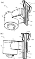
- FIGS. 1 and Figure 2 are perspective views of the detector 100, in which the PIR sensor 102 can be seen.
- the detector 100 comprises a main housing 116 which houses the PIR sensor 102 and any other electronic components.
- the main housing 116 is pivotally mounted to a bracket 118, such that the main housing 116 can be rotated with respect to the support member 118 about an axis transverse to the axis of the PIR sensor 102.
- the bracket 118 is slidably mounted to an elongate member 136.
- the bracket 118 comprises a first and second jaw 122 which embrace the edges of the elongate member 136 and slidably attach the bracket 118 to the elongate member 136.
- the longitudinal edges of the elongate member 136 are each provided with a respective toothed rack 124, and each jaw 122 of the bracket 118 comprises a pawl 126, which engages a respective rack 124 to prevent the bracket 118 from sliding relative to the elongate member 136.
- the pawls 126 are moved outwardly, as indicated by the arrows in Figure 2 .
- This causes the jaws 122 to elastically deform so that the pawls 126 are lifted free of the racks 124.
- the bracket 118 can then be slid up and down the elongate member 136 as desired, until the pawls 126 are released and so re-engage the racks 124, locking the bracket in place with respect to the elongate member.
- This can be achieved with hand force from a user, but the weight of the assembled housing is insufficient to cause movement of the bracket 118 relative to the elongate member when the pawls 126 engage the racks 124.
- the elongate member 136 is provided with two opposing members in the form of first and second hooks 128.
- the hooks 128 are connected to the elongate member 136 by a transverse member 137 and extend therefrom towards the proximal end of the elongate member 136.
- the hooks 128 are formed of resilient material and are angled towards the elongate member at their proximal ends. In this way, when a portion of a light fitting is interposed between the hooks 128 and the elongate member 136, the hooks 128 act to urge the elongate member 136 against the light fitting to secure the detector in position.
- the weight of the assembled housing 116 acts via the elongate member 136 against the resilience of the hooks 128 to provide a stable location of the detector.
- FIG. 3 shows the detector 100 attached to a linear fluorescent louvre 130.
- the louvre 130 comprises a fluorescent strip light and a housing for that fluorescent strip light.
- the housing comprises curved side pieces 132 and cross pieces 134.
- the curved side pieces 132 and the cross pieces 134 are typically made out of a reflective material, so that light from the fluorescent strip light is reflected downwards instead of being absorbed and scattered by the ceiling above.
- the detector 100 can be attached to the louvre 130 by placing the hooks 128 over the cross pieces 134.
- the elongate member 136 then rests against the cross piece 134, and the PIR sensor 102 is afforded a clear view below the louvre 130.
- the transverse member 137 engages the upper edge of the cross piece 134. Precisely where the PIR sensor 102 is directed can be adjusted by rotating the housing 116 with respect to the bracket 118 and sliding the bracket 118 with respect to the elongate member 136.
- the lighting controller 112 is arranged to control the louvre 130, such that when a person walks underneath the louvre 130 they are detected by the PIR sensor 102 and an activation signal is sent which causes the lighting controller 112 to activate the fluorescent strip light, providing the person with light.
- each hook 128 is nearly flush with the body 136 of the retaining member 120, in order to provide a close and consequently secure fit for the retaining member 120 when it is attached to a thin object such as the cross piece 134.
- the hooks 128 are also curved and capable of elastic deformation, such that a wider object can be inserted between the hooks 128 and the body 136 by deforming the hooks so that they straighten to allow the wider object's passage.
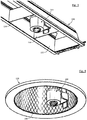
- Figure 4 shows the detector 100 attached to a compact fluorescent reflector 138.
- the reflector 138 comprises a reflective concave surface 140, which again directs the light of a compact fluorescent light downwards.
- the detector 100 can be hooked to the edge of the reflective concave surface 140.
- the lighting controller is arranged to activate both the compact fluorescent light in the reflector 138, and a plurality of other similar lights nearby, in response to an activation signal from the detector 100. Therefore, when a person is detected passing underneath the reflector 138, a large area is automatically illuminated.
- embodiments of the present invention relate to a detector (100) suitable for attaching to a light fitting.
- the detector comprises a passive infra red sensor (102) and a clip (128) suitable for suspending the detector from a light fitting.
Landscapes
- Physics & Mathematics (AREA)
- General Physics & Mathematics (AREA)
- Spectroscopy & Molecular Physics (AREA)
- Engineering & Computer Science (AREA)
- General Engineering & Computer Science (AREA)
- Arrangement Of Elements, Cooling, Sealing, Or The Like Of Lighting Devices (AREA)
- Circuit Arrangement For Electric Light Sources In General (AREA)
- Photometry And Measurement Of Optical Pulse Characteristics (AREA)
- Spectrometry And Color Measurement (AREA)
- Fire Alarms (AREA)
Applications Claiming Priority (2)
| Application Number | Priority Date | Filing Date | Title |
|---|---|---|---|
| GB1201002.1A GB2498572B (en) | 2012-01-20 | 2012-01-20 | Detector configured to detect the presence of a person |
| PCT/GB2013/050132 WO2013108052A1 (en) | 2012-01-20 | 2013-01-21 | Detector |
Publications (2)
| Publication Number | Publication Date |
|---|---|
| EP2805312A1 EP2805312A1 (en) | 2014-11-26 |
| EP2805312B1 true EP2805312B1 (en) | 2017-11-22 |
Family
ID=45840763
Family Applications (1)
| Application Number | Title | Priority Date | Filing Date |
|---|---|---|---|
| EP13702502.9A Not-in-force EP2805312B1 (en) | 2012-01-20 | 2013-01-21 | Detector |
Country Status (7)
| Country | Link |
|---|---|
| US (1) | US9400216B2 (OSRAM) |
| EP (1) | EP2805312B1 (OSRAM) |
| CN (1) | CN104067323B (OSRAM) |
| AU (1) | AU2013210894A1 (OSRAM) |
| GB (1) | GB2498572B (OSRAM) |
| IN (1) | IN2014KN01609A (OSRAM) |
| WO (1) | WO2013108052A1 (OSRAM) |
Families Citing this family (6)
| Publication number | Priority date | Publication date | Assignee | Title |
|---|---|---|---|---|
| WO2017045174A1 (zh) * | 2015-09-16 | 2017-03-23 | 尚平 | 一种户外红外线感应报警器 |
| CN105717798B (zh) * | 2016-03-16 | 2018-10-26 | 陈丹红 | 一种智能家居立体卫士 |
| US11355008B2 (en) | 2017-06-30 | 2022-06-07 | Signify Holding B.V. | Lighting system with traffic rerouting functionality |
| USD930493S1 (en) * | 2019-12-16 | 2021-09-14 | A.Keemplecom Limited | Motion sensor |
| US20220268430A1 (en) * | 2021-02-25 | 2022-08-25 | Axis Lighting Inc. | Luminaire structure |
| CN221592694U (zh) * | 2024-02-06 | 2024-08-23 | 深圳市思坎普科技有限公司 | 可外挂的感应装置及灯具 |
Family Cites Families (18)
| Publication number | Priority date | Publication date | Assignee | Title |
|---|---|---|---|---|
| US6091200A (en) * | 1998-12-17 | 2000-07-18 | Lenz; Mark | Fluorescent light and motion detector with quick plug release and troubleshooting capabilities |
| CN2445388Y (zh) * | 2000-06-07 | 2001-08-29 | 郭赐福 | 嵌顶式可调角度红外线自动侦测感测器 |
| JP2003317537A (ja) * | 2002-04-25 | 2003-11-07 | Kaoru Moriyama | 電球アダプター |
| JP4333338B2 (ja) * | 2003-11-25 | 2009-09-16 | パナソニック電工株式会社 | 照明器具 |
| US7234841B2 (en) * | 2004-01-13 | 2007-06-26 | Hubbell Incorporated | Adjustable support for an electrical assembly |
| US7109880B2 (en) * | 2004-03-12 | 2006-09-19 | Desa Ip Llc | Ceiling mount light with 360-degree motion sensor |
| US20050281021A1 (en) * | 2004-06-21 | 2005-12-22 | Thompson Harvey J | Flashlight assembly and a method of using the same |
| DE102005047496A1 (de) * | 2005-10-04 | 2007-04-12 | Louis Chuang | Leuchtvorrichtung |
| CN200968525Y (zh) * | 2006-07-04 | 2007-10-31 | 贵州首朗新能源有限公司 | 红外无线遥控半导体照明灯 |
| US8636385B2 (en) * | 2006-12-15 | 2014-01-28 | Koninklijke Philips N.V. | Sensor module connector |
| US7490960B1 (en) * | 2006-12-15 | 2009-02-17 | Genlyte Thomas Group Llc | Add-on sensor module for lighting system |
| US7862202B2 (en) * | 2007-03-30 | 2011-01-04 | Cooper Technologies Company | Method and apparatus for installing a motion sensor in a luminaire |
| US8092041B2 (en) * | 2007-04-20 | 2012-01-10 | Hubbell Incorporated | Low profile linear high bay fluorescent luminaire |
| US7703952B2 (en) * | 2007-08-27 | 2010-04-27 | Aitec Co., Ltd. | Lamp support |
| CN201196367Y (zh) * | 2008-05-15 | 2009-02-18 | 王建春 | 一种人体感应灯 |
| JP5156520B2 (ja) * | 2008-07-28 | 2013-03-06 | パナソニック株式会社 | センサ脱着式照明器具 |
| GB0822648D0 (en) * | 2008-12-12 | 2009-01-21 | Burnham Douglas P | A sensing device |
| WO2011124400A2 (de) * | 2010-04-09 | 2011-10-13 | Tridonic Ag | Sensor für eine beleuchtungsanlage |
-
2012
- 2012-01-20 GB GB1201002.1A patent/GB2498572B/en active Active
-
2013
- 2013-01-21 IN IN1609KON2014 patent/IN2014KN01609A/en unknown
- 2013-01-21 EP EP13702502.9A patent/EP2805312B1/en not_active Not-in-force
- 2013-01-21 WO PCT/GB2013/050132 patent/WO2013108052A1/en not_active Ceased
- 2013-01-21 US US14/373,474 patent/US9400216B2/en active Active
- 2013-01-21 AU AU2013210894A patent/AU2013210894A1/en not_active Abandoned
- 2013-01-21 CN CN201380006171.9A patent/CN104067323B/zh active Active
Also Published As
| Publication number | Publication date |
|---|---|
| IN2014KN01609A (OSRAM) | 2015-10-23 |
| CN104067323B (zh) | 2017-08-11 |
| GB2498572A (en) | 2013-07-24 |
| AU2013210894A1 (en) | 2014-08-14 |
| CN104067323A (zh) | 2014-09-24 |
| US20150008325A1 (en) | 2015-01-08 |
| GB2498572B (en) | 2014-12-03 |
| GB201201002D0 (en) | 2012-03-07 |
| WO2013108052A1 (en) | 2013-07-25 |
| EP2805312A1 (en) | 2014-11-26 |
| US9400216B2 (en) | 2016-07-26 |
Similar Documents
| Publication | Publication Date | Title |
|---|---|---|
| EP2805312B1 (en) | Detector | |
| US11901138B2 (en) | Remote controlled light switch cover | |
| US5673022A (en) | Motion sensor/photoelectric light sensor plug-in receptacle | |
| EP2643841B1 (en) | A controller for use with a mechanical switch | |
| US9091111B2 (en) | System and method for concealing and accessing objects behind a surface | |
| CA2977655C (en) | Illuminated threshold barrier | |
| US10393362B2 (en) | Illuminated handle system | |
| US20140375221A1 (en) | Battery-powered light level sensing device | |
| JP2014191918A (ja) | 環境制御システム | |
| KR20190000019U (ko) | 센서를 구비한 조명등 | |
| KR20080096167A (ko) | 야간 작동 스텝라이트 및 스텝라이트를 이용한 조도조절방법 | |
| US8113686B2 (en) | Guideway illuminator | |
| WO2013126967A1 (en) | Building services control system | |
| KR20090006142U (ko) | 센서분리형 조명등장치 | |
| AU2016230918B2 (en) | Panel assembly | |
| JPH08298187A (ja) | 住宅における設備機器制御装置 | |
| KR102813646B1 (ko) | Tof 안전센서를 이용한 자동문 시스템 | |
| KR20130033528A (ko) | 조명 및 공조 제어 시스템 | |
| NL2019934B1 (en) | Ultrasonic motion detection arrangement | |
| KR20130054581A (ko) | 선박용 조명 제어 시스템 | |
| AU2018274839B2 (en) | Mounting Bracket | |
| NL1005292C1 (nl) | Passieve infrarood bewegingschakelaar voorzien van een lampvoet en een lamphouder. | |
| AU2004100451A4 (en) | Smoke detectable deadlock | |
| JP2014134005A (ja) | 照明ユニット、及び、該照明ユニットを備えた開口部装置 | |
| GB2572054A (en) | Improved sensor assembly |
Legal Events
| Date | Code | Title | Description |
|---|---|---|---|
| PUAI | Public reference made under article 153(3) epc to a published international application that has entered the european phase |
Free format text: ORIGINAL CODE: 0009012 |
|
| 17P | Request for examination filed |
Effective date: 20140808 |
|
| AK | Designated contracting states |
Kind code of ref document: A1 Designated state(s): AL AT BE BG CH CY CZ DE DK EE ES FI FR GB GR HR HU IE IS IT LI LT LU LV MC MK MT NL NO PL PT RO RS SE SI SK SM TR |
|
| DAX | Request for extension of the european patent (deleted) | ||
| 17Q | First examination report despatched |
Effective date: 20160205 |
|
| GRAP | Despatch of communication of intention to grant a patent |
Free format text: ORIGINAL CODE: EPIDOSNIGR1 |
|
| INTG | Intention to grant announced |
Effective date: 20170606 |
|
| GRAS | Grant fee paid |
Free format text: ORIGINAL CODE: EPIDOSNIGR3 |
|
| GRAA | (expected) grant |
Free format text: ORIGINAL CODE: 0009210 |
|
| AK | Designated contracting states |
Kind code of ref document: B1 Designated state(s): AL AT BE BG CH CY CZ DE DK EE ES FI FR GB GR HR HU IE IS IT LI LT LU LV MC MK MT NL NO PL PT RO RS SE SI SK SM TR |
|
| REG | Reference to a national code |
Ref country code: GB Ref legal event code: FG4D |
|
| REG | Reference to a national code |
Ref country code: CH Ref legal event code: EP |
|
| REG | Reference to a national code |
Ref country code: IE Ref legal event code: FG4D |
|
| REG | Reference to a national code |
Ref country code: AT Ref legal event code: REF Ref document number: 949075 Country of ref document: AT Kind code of ref document: T Effective date: 20171215 |
|
| REG | Reference to a national code |
Ref country code: DE Ref legal event code: R096 Ref document number: 602013029732 Country of ref document: DE |
|
| REG | Reference to a national code |
Ref country code: NL Ref legal event code: MP Effective date: 20171122 |
|
| REG | Reference to a national code |
Ref country code: LT Ref legal event code: MG4D |
|
| REG | Reference to a national code |
Ref country code: AT Ref legal event code: MK05 Ref document number: 949075 Country of ref document: AT Kind code of ref document: T Effective date: 20171122 |
|
| PG25 | Lapsed in a contracting state [announced via postgrant information from national office to epo] |
Ref country code: SE Free format text: LAPSE BECAUSE OF FAILURE TO SUBMIT A TRANSLATION OF THE DESCRIPTION OR TO PAY THE FEE WITHIN THE PRESCRIBED TIME-LIMIT Effective date: 20171122 Ref country code: NL Free format text: LAPSE BECAUSE OF FAILURE TO SUBMIT A TRANSLATION OF THE DESCRIPTION OR TO PAY THE FEE WITHIN THE PRESCRIBED TIME-LIMIT Effective date: 20171122 Ref country code: LT Free format text: LAPSE BECAUSE OF FAILURE TO SUBMIT A TRANSLATION OF THE DESCRIPTION OR TO PAY THE FEE WITHIN THE PRESCRIBED TIME-LIMIT Effective date: 20171122 Ref country code: NO Free format text: LAPSE BECAUSE OF FAILURE TO SUBMIT A TRANSLATION OF THE DESCRIPTION OR TO PAY THE FEE WITHIN THE PRESCRIBED TIME-LIMIT Effective date: 20180222 Ref country code: FI Free format text: LAPSE BECAUSE OF FAILURE TO SUBMIT A TRANSLATION OF THE DESCRIPTION OR TO PAY THE FEE WITHIN THE PRESCRIBED TIME-LIMIT Effective date: 20171122 Ref country code: ES Free format text: LAPSE BECAUSE OF FAILURE TO SUBMIT A TRANSLATION OF THE DESCRIPTION OR TO PAY THE FEE WITHIN THE PRESCRIBED TIME-LIMIT Effective date: 20171122 |
|
| PG25 | Lapsed in a contracting state [announced via postgrant information from national office to epo] |
Ref country code: LV Free format text: LAPSE BECAUSE OF FAILURE TO SUBMIT A TRANSLATION OF THE DESCRIPTION OR TO PAY THE FEE WITHIN THE PRESCRIBED TIME-LIMIT Effective date: 20171122 Ref country code: BG Free format text: LAPSE BECAUSE OF FAILURE TO SUBMIT A TRANSLATION OF THE DESCRIPTION OR TO PAY THE FEE WITHIN THE PRESCRIBED TIME-LIMIT Effective date: 20180222 Ref country code: HR Free format text: LAPSE BECAUSE OF FAILURE TO SUBMIT A TRANSLATION OF THE DESCRIPTION OR TO PAY THE FEE WITHIN THE PRESCRIBED TIME-LIMIT Effective date: 20171122 Ref country code: RS Free format text: LAPSE BECAUSE OF FAILURE TO SUBMIT A TRANSLATION OF THE DESCRIPTION OR TO PAY THE FEE WITHIN THE PRESCRIBED TIME-LIMIT Effective date: 20171122 Ref country code: AT Free format text: LAPSE BECAUSE OF FAILURE TO SUBMIT A TRANSLATION OF THE DESCRIPTION OR TO PAY THE FEE WITHIN THE PRESCRIBED TIME-LIMIT Effective date: 20171122 Ref country code: GR Free format text: LAPSE BECAUSE OF FAILURE TO SUBMIT A TRANSLATION OF THE DESCRIPTION OR TO PAY THE FEE WITHIN THE PRESCRIBED TIME-LIMIT Effective date: 20180223 |
|
| PG25 | Lapsed in a contracting state [announced via postgrant information from national office to epo] |
Ref country code: CZ Free format text: LAPSE BECAUSE OF FAILURE TO SUBMIT A TRANSLATION OF THE DESCRIPTION OR TO PAY THE FEE WITHIN THE PRESCRIBED TIME-LIMIT Effective date: 20171122 Ref country code: SK Free format text: LAPSE BECAUSE OF FAILURE TO SUBMIT A TRANSLATION OF THE DESCRIPTION OR TO PAY THE FEE WITHIN THE PRESCRIBED TIME-LIMIT Effective date: 20171122 Ref country code: CY Free format text: LAPSE BECAUSE OF FAILURE TO SUBMIT A TRANSLATION OF THE DESCRIPTION OR TO PAY THE FEE WITHIN THE PRESCRIBED TIME-LIMIT Effective date: 20171122 Ref country code: EE Free format text: LAPSE BECAUSE OF FAILURE TO SUBMIT A TRANSLATION OF THE DESCRIPTION OR TO PAY THE FEE WITHIN THE PRESCRIBED TIME-LIMIT Effective date: 20171122 Ref country code: DK Free format text: LAPSE BECAUSE OF FAILURE TO SUBMIT A TRANSLATION OF THE DESCRIPTION OR TO PAY THE FEE WITHIN THE PRESCRIBED TIME-LIMIT Effective date: 20171122 |
|
| REG | Reference to a national code |
Ref country code: DE Ref legal event code: R119 Ref document number: 602013029732 Country of ref document: DE |
|
| PG25 | Lapsed in a contracting state [announced via postgrant information from national office to epo] |
Ref country code: PL Free format text: LAPSE BECAUSE OF FAILURE TO SUBMIT A TRANSLATION OF THE DESCRIPTION OR TO PAY THE FEE WITHIN THE PRESCRIBED TIME-LIMIT Effective date: 20171122 Ref country code: RO Free format text: LAPSE BECAUSE OF FAILURE TO SUBMIT A TRANSLATION OF THE DESCRIPTION OR TO PAY THE FEE WITHIN THE PRESCRIBED TIME-LIMIT Effective date: 20171122 Ref country code: IT Free format text: LAPSE BECAUSE OF FAILURE TO SUBMIT A TRANSLATION OF THE DESCRIPTION OR TO PAY THE FEE WITHIN THE PRESCRIBED TIME-LIMIT Effective date: 20171122 Ref country code: SM Free format text: LAPSE BECAUSE OF FAILURE TO SUBMIT A TRANSLATION OF THE DESCRIPTION OR TO PAY THE FEE WITHIN THE PRESCRIBED TIME-LIMIT Effective date: 20171122 |
|
| REG | Reference to a national code |
Ref country code: CH Ref legal event code: PL |
|
| PLBE | No opposition filed within time limit |
Free format text: ORIGINAL CODE: 0009261 |
|
| STAA | Information on the status of an ep patent application or granted ep patent |
Free format text: STATUS: NO OPPOSITION FILED WITHIN TIME LIMIT |
|
| GBPC | Gb: european patent ceased through non-payment of renewal fee |
Effective date: 20180222 |
|
| 26N | No opposition filed |
Effective date: 20180823 |
|
| PG25 | Lapsed in a contracting state [announced via postgrant information from national office to epo] |
Ref country code: LU Free format text: LAPSE BECAUSE OF NON-PAYMENT OF DUE FEES Effective date: 20180121 Ref country code: DE Free format text: LAPSE BECAUSE OF NON-PAYMENT OF DUE FEES Effective date: 20180801 Ref country code: FR Free format text: LAPSE BECAUSE OF NON-PAYMENT OF DUE FEES Effective date: 20180131 |
|
| REG | Reference to a national code |
Ref country code: IE Ref legal event code: MM4A |
|
| REG | Reference to a national code |
Ref country code: FR Ref legal event code: ST Effective date: 20180928 |
|
| REG | Reference to a national code |
Ref country code: BE Ref legal event code: MM Effective date: 20180131 |
|
| PG25 | Lapsed in a contracting state [announced via postgrant information from national office to epo] |
Ref country code: SI Free format text: LAPSE BECAUSE OF FAILURE TO SUBMIT A TRANSLATION OF THE DESCRIPTION OR TO PAY THE FEE WITHIN THE PRESCRIBED TIME-LIMIT Effective date: 20171122 Ref country code: CH Free format text: LAPSE BECAUSE OF NON-PAYMENT OF DUE FEES Effective date: 20180131 Ref country code: LI Free format text: LAPSE BECAUSE OF NON-PAYMENT OF DUE FEES Effective date: 20180131 Ref country code: BE Free format text: LAPSE BECAUSE OF NON-PAYMENT OF DUE FEES Effective date: 20180131 |
|
| PG25 | Lapsed in a contracting state [announced via postgrant information from national office to epo] |
Ref country code: IE Free format text: LAPSE BECAUSE OF NON-PAYMENT OF DUE FEES Effective date: 20180121 |
|
| PG25 | Lapsed in a contracting state [announced via postgrant information from national office to epo] |
Ref country code: GB Free format text: LAPSE BECAUSE OF NON-PAYMENT OF DUE FEES Effective date: 20180222 |
|
| PG25 | Lapsed in a contracting state [announced via postgrant information from national office to epo] |
Ref country code: MC Free format text: LAPSE BECAUSE OF FAILURE TO SUBMIT A TRANSLATION OF THE DESCRIPTION OR TO PAY THE FEE WITHIN THE PRESCRIBED TIME-LIMIT Effective date: 20171122 |
|
| PG25 | Lapsed in a contracting state [announced via postgrant information from national office to epo] |
Ref country code: MT Free format text: LAPSE BECAUSE OF NON-PAYMENT OF DUE FEES Effective date: 20180121 |
|
| PG25 | Lapsed in a contracting state [announced via postgrant information from national office to epo] |
Ref country code: TR Free format text: LAPSE BECAUSE OF FAILURE TO SUBMIT A TRANSLATION OF THE DESCRIPTION OR TO PAY THE FEE WITHIN THE PRESCRIBED TIME-LIMIT Effective date: 20171122 |
|
| PG25 | Lapsed in a contracting state [announced via postgrant information from national office to epo] |
Ref country code: HU Free format text: LAPSE BECAUSE OF FAILURE TO SUBMIT A TRANSLATION OF THE DESCRIPTION OR TO PAY THE FEE WITHIN THE PRESCRIBED TIME-LIMIT; INVALID AB INITIO Effective date: 20130121 Ref country code: PT Free format text: LAPSE BECAUSE OF FAILURE TO SUBMIT A TRANSLATION OF THE DESCRIPTION OR TO PAY THE FEE WITHIN THE PRESCRIBED TIME-LIMIT Effective date: 20171122 |
|
| PG25 | Lapsed in a contracting state [announced via postgrant information from national office to epo] |
Ref country code: MK Free format text: LAPSE BECAUSE OF NON-PAYMENT OF DUE FEES Effective date: 20171122 |
|
| PG25 | Lapsed in a contracting state [announced via postgrant information from national office to epo] |
Ref country code: AL Free format text: LAPSE BECAUSE OF FAILURE TO SUBMIT A TRANSLATION OF THE DESCRIPTION OR TO PAY THE FEE WITHIN THE PRESCRIBED TIME-LIMIT Effective date: 20171122 Ref country code: IS Free format text: LAPSE BECAUSE OF FAILURE TO SUBMIT A TRANSLATION OF THE DESCRIPTION OR TO PAY THE FEE WITHIN THE PRESCRIBED TIME-LIMIT Effective date: 20180322 |