EP2805035B1 - Kühlanordnung für einen ventilsitz - Google Patents
Kühlanordnung für einen ventilsitz Download PDFInfo
- Publication number
- EP2805035B1 EP2805035B1 EP13702078.0A EP13702078A EP2805035B1 EP 2805035 B1 EP2805035 B1 EP 2805035B1 EP 13702078 A EP13702078 A EP 13702078A EP 2805035 B1 EP2805035 B1 EP 2805035B1
- Authority
- EP
- European Patent Office
- Prior art keywords
- cylinder head
- cooling
- seat insert
- duct
- connecting pipe
- Prior art date
- Legal status (The legal status is an assumption and is not a legal conclusion. Google has not performed a legal analysis and makes no representation as to the accuracy of the status listed.)
- Active
Links
Images
Classifications
-
- F—MECHANICAL ENGINEERING; LIGHTING; HEATING; WEAPONS; BLASTING
- F01—MACHINES OR ENGINES IN GENERAL; ENGINE PLANTS IN GENERAL; STEAM ENGINES
- F01L—CYCLICALLY OPERATING VALVES FOR MACHINES OR ENGINES
- F01L3/00—Lift-valve, i.e. cut-off apparatus with closure members having at least a component of their opening and closing motion perpendicular to the closing faces; Parts or accessories thereof
- F01L3/12—Cooling of valves
-
- F—MECHANICAL ENGINEERING; LIGHTING; HEATING; WEAPONS; BLASTING
- F01—MACHINES OR ENGINES IN GENERAL; ENGINE PLANTS IN GENERAL; STEAM ENGINES
- F01P—COOLING OF MACHINES OR ENGINES IN GENERAL; COOLING OF INTERNAL-COMBUSTION ENGINES
- F01P3/00—Liquid cooling
- F01P3/12—Arrangements for cooling other engine or machine parts
- F01P3/14—Arrangements for cooling other engine or machine parts for cooling intake or exhaust valves
-
- F—MECHANICAL ENGINEERING; LIGHTING; HEATING; WEAPONS; BLASTING
- F01—MACHINES OR ENGINES IN GENERAL; ENGINE PLANTS IN GENERAL; STEAM ENGINES
- F01L—CYCLICALLY OPERATING VALVES FOR MACHINES OR ENGINES
- F01L3/00—Lift-valve, i.e. cut-off apparatus with closure members having at least a component of their opening and closing motion perpendicular to the closing faces; Parts or accessories thereof
- F01L3/12—Cooling of valves
- F01L3/16—Cooling of valves by means of a fluid flowing through or along valve, e.g. air
- F01L3/18—Liquid cooling of valve
Definitions
- the present invention relates to a cooling arrangement for a valve seat of a piston engine in accordance with the preamble of claim 1.
- the task of the cylinder head is to close the upper end of the cylinder sleeve and form the upper part of the combustion chamber.
- the cylinder head accommodates inlet and exhaust passages for the gases of the combustion process and provides a base for the valve gear and in a diesel engine for the fuel injection valve.
- the cylinder head is also provided with cooling ducts for cooling the components that require cooling.
- One of the components in the cylinder head that needs to be cooled is the exhaust valve seat insert, i.e. the counter surface for the exhaust valve disc, which surface is subject to high thermal loading. If the seat insert heats up excessively, it may develop permanent deformations causing leakage in the exhaust valve.
- the cooling ducts in the cylinder head may be arranged as close to the seat insert as possible, or a separate cooling duct for cooling liquid may be adapted in conjunction with the seat insert.
- Problems related to this kind of solutions include insufficient cooling effect and cooling liquid leakages. These problems have been solved for example by a valve seat insert disclosed in patent application FI 20065722 A .
- the valve seat insert comprises a cooling duct, an inlet port for conveying cooling liquid into the cooling duct, and an outlet port for discharging cooling liquid out of the cooling duct.
- the inlet port and the outlet port are arranged close to one another.
- the cooling duct is arranged between the inlet port and the outlet port so that it extends at least almost around the whole seat insert.
- a remaining problem is the sealing between the seat insert and the cooling ducts of the cylinder head. Leakages are normally prevented by applying liquid sealant to the joints between the cooling ducts of the cylinder head and the seat insert. When the sealant hardens, it seals the joints between the parts. The liquid sealant works for some time, but after longer use of the engine leakages often occur.
- the object of the present invention is to provide an improved cooling arrangement for a valve seat of a piston engine.
- the characterizing features of the cooling arrangement according to the present invention are given in the characterizing part of claim 1.
- the cooling arrangement comprises a cylinder head comprising an inlet duct and an outlet duct for cooling liquid, and a valve seat insert, which seat insert is arranged against the cylinder head and comprises a cooling duct, an inlet port that is arranged on the outer circumference of the seat insert and in fluid communication with the inlet duct of the cylinder head for conveying cooling liquid into the cooling duct, and an outlet port that is arranged on the outer circumference of the seat insert and in fluid communication with the outlet duct of the cylinder head for discharging cooling liquid out of the cooling duct.
- the arrangement further comprises at least one connecting pipe that is arranged inside the inlet duct or the outlet duct of the cylinder head and against the seat insert, and a seal that is arranged between the connecting pipe and the seat insert.
- cooling arrangement With the cooling arrangement according to the invention, leakages from the valve seat cooling system can be prevented.
- the arrangement is more reliable than conventional cooling systems, where joints between the cylinder head and the seat insert are sealed with liquid sealant. When the seal is damaged, it can be easily replaced. Also existing cooling arrangements can be upgraded with an arrangement according to the invention.
- the arrangement comprises a second seal that is arranged between the connecting pipe and the inlet or outlet duct of the cylinder head.
- the second seal prevents leakages between the connecting pipe and the cylinder head.
- additional seals could be arranged between the connecting pipe and a separate locking pipe and between the locking pipe and the cylinder head.
- the connecting pipe is provided with a screw thread on the outer surface of the pipe for fastening the connecting pipe to the inlet or outlet duct of the cylinder head. With the thread the connecting pipe can be easily fastened and removed.
- the arrangement comprises a locking pipe that is provided with a screw thread on the outer surface of the pipe for fastening the locking pipe to the inlet or outlet duct of the cylinder head and for clamping the connecting pipe between the locking pipe and the seat insert.
- the locking pipe can replace the thread of the connecting pipe.
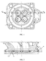
- Figure 1 shows a cylinder head 1 of a large internal combustion engine.
- the engine is a four-stroke piston engine, which can be used, for instance, as a main or an auxiliary engine of a ship or an engine that is used at a power plant for producing electricity.
- the task of the cylinder head 1 is to close the upper end of the cylinder sleeve and form the upper part of the combustion chamber of the cylinder.
- the cylinder head 1 is provided with an inlet passage and an exhaust passage for the gases of the cylinder's combustion process. The gas flow through the inlet passage and the exhaust passage is controlled by valves that are arranged in conjunction with the passages.
- the cylinder head 1 also acts as a base for the valve gear and in a diesel engine for the fuel injection valve.
- Each cylinder of the engine is provided with two intake valves and two exhaust valves.
- the gas exchange valves comprise a valve stem and a valve disc that cooperates with a valve seat.
- the exhaust valve seats have a high thermal load and are therefore provided with a cooling arrangement.
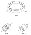
- the cooling arrangement comprises a valve seat insert 2 shown in figure 5 .
- the seat insert 2 comprises an annular cooling duct 10 (not shown in Fig. 5 ) that is arranged completely inside the seat insert 2.
- the cooling duct 10 is provided with an inlet port 11 for conveying cooling liquid into the cooling duct 10 and with an outlet port 12 for discharging the cooling liquid out of the cooling duct 10.
- the inlet port 11 and the outlet port 12 are arranged on the outer circumference of the seat insert 2.
- the cooling duct 10 is arranged between the inlet port 11 and the outlet port 12 so that it extends almost around the whole seat insert 2.
- the seat insert 2 is a one-piece part, for instance a one-piece cast, which is manufactured by casting.
- the seat insert 2 may be manufactured by using a powder metallurgical manufacturing method, for instance hot isostatic pressing (HIP).
- Cooling liquid is supplied through the inlet port 11 into the cooling duct 10.
- the cooling liquid circulates in the cooling duct 10 almost around the whole seat insert 2 and is then discharged from the cooling duct 10 through the outlet port 12.
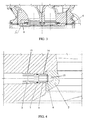
- the seat insert 2 is attached to the cylinder head 1 by a shrinkage fit.
- the cylinder head 1 is provided with an inlet duct 8 for supplying cooling liquid to the seat insert 2 and with an outlet duct 9 for discharging cooling liquid from the seat insert 2.
- the inlet duct 8 and the outlet duct 9 can be accessed by removing a plug 4 at the end of the duct 8, 9.
- the inlet port 11 of the seat insert 1 is aligned with the inlet duct 8 of the cylinder head 1 and the outlet port 12 of the seat insert 2 is aligned with the outlet duct of the cylinder head 1.
- a connecting pipe 3 is used for improving sealing between the cylinder head 1 and the seat insert 2.
- the connecting pipe 3 is shown in figure 6 .
- FIGS 2 to 4 is shown a cross-sectional view of the connecting pipe 3.
- Both the inlet duct 8 and the outlet duct 9 of the cylinder head 1 are provided with a connecting pipe 3.
- a seal 6 is arranged between the inlet port 11 of the seat insert 2 and the connecting pipe 3.
- An identical seal 6 is arranged between the outlet port 12 of the seat insert 2 and the connecting pipe 3.
- the seal 6 is between the end of the connecting pipe 3 and the respective inlet or outlet port 11, 12.
- the seal 6 prevents leaking between the seat insert 2 and the connecting pipe 3.
- An annular groove 13 is arranged on the outer surface of the connecting pipe 3 for accommodating a sealing ring 7.
- the sealing ring 7 prevents leaking between the connecting pipe 3 and the cylinder head 1.
- the connecting pipe 3 is provided with a screw thread 14 that is arranged on the outer surface of the pipe 3. A similar thread is arranged in the inlet or outlet duct 8, 9 of the cylinder head 1.
- the connecting pipe 3 is provided with a hexagon socket head 16.
- the connecting pipe 3 can thus be fastened and removed by using a hex wrench (Allen key). It is also possible to use other socket shapes.
- the arrangement can be provided with a locking pipe 5.
- the locking pipe 5 is similar to the connecting pipe 3 and is arranged in the inlet or outlet duct 8, 9 of the cylinder head 1. The connecting pipe 3 is clamped between the seat insert 2 and the locking pipe 5.
- a screw thread 15 is arranged on the outer surface of the locking pipe 5 for fastening the locking pipe 5 to the cylinder head 1.
- a similar thread is arranged in the inlet or outlet duct 8, 9 of the cylinder head 1.
- the thread 15 of the locking pipe 5 is oriented in the opposite direction compared to the thread 14 of the connecting pipe 3.
- the connecting pipe 3 is provided with a right-hand thread
- the locking pipe 5 is provided with a lefthand thread. If the connecting pipe 3 starts to turn open, it will tighten the locking pipe 5 and loosening of the pipes 3, 5 is prevented.
- the locking pipe 5 is provided with a hexagon socket head 17 for fastening the pipe 5.
Landscapes
- Engineering & Computer Science (AREA)
- Mechanical Engineering (AREA)
- General Engineering & Computer Science (AREA)
- Chemical & Material Sciences (AREA)
- Combustion & Propulsion (AREA)
- Physics & Mathematics (AREA)
- Fluid Mechanics (AREA)
- Cylinder Crankcases Of Internal Combustion Engines (AREA)
- Lift Valve (AREA)
Claims (5)
- Kühlanordnung für einen Ventilsitz eines Kolbenmotors, wobei die Kühlanordnung Folgendes umfasst:- einen Zylinderkopf (1), der einen Einlasskanal (8) und einen Auslasskanal (9) zum Kühlen von Flüssigkeit umfasst, und- einen Ventilsitzring (2), wobei der Sitzring (2) gegen den Zylinderkopf (1) angeordnet ist und einen Kühlkanal (10), eine Einlassöffnung (11), die am Außenumfang des Sitzrings (2) angeordnet ist und mit dem Einlasskanal (8) des Zylinderkopfs (1) in Fluidverbindung steht, um Kühlflüssigkeit in den Kühlkanal (10) zu befördern, und eine Auslassöffnung (12), die am Außenumfang des Sitzrings (2) angeordnet ist und mit dem Auslasskanal (9) des Zylinderkopfs (1) in Fluidverbindung steht, um Kühlflüssigkeit aus dem Kühlkanal (10) abzuführen, umfasst,dadurch gekennzeichnet, dass die Anordnung ferner Folgendes umfasst- mindestens ein Verbindungsrohr (3), das innerhalb des Einlasskanals (8) oder des Auslasskanals (9) des Zylinderkopfs (1) und gegen den Sitzring (2) angeordnet ist, und- eine Dichtung (6), die zwischen dem Verbindungsrohr (3) und dem Sitzring (2) angeordnet ist.
- Anordnung nach Anspruch 1, dadurch gekennzeichnet, dass die Anordnung eine zweite Dichtung (7) umfasst, die zwischen dem Verbindungsrohr (3) und dem Einlass- oder Auslasskanal (8, 9) des Zylinderkopfs (1) angeordnet ist.
- Anordnung nach Anspruch 1 oder 2, dadurch gekennzeichnet, dass das Verbindungsrohr (3) auf der Außenfläche des Rohrs (3) mit einem Schraubgewinde (14) versehen ist, um das Verbindungsrohr (3) an dem Einlass- oder Auslasskanal (8, 9) des Zylinderkopfs (1) zu befestigen.
- Anordnung nach einem der Ansprüche 1 - 3, dadurch gekennzeichnet, dass die Anordnung ein Verriegelungsrohr (5) umfasst, das an der Außenfläche des Rohrs (5) mit einem Schraubgewinde (15) versehen ist, um das Verriegelungsrohr (5) an dem Einlass- oder Auslasskanal (8, 9) des Zylinderkopfs (1) zu befestigen und um das Verbindungsrohr (3) zwischen dem Verriegelungsrohr (5) und dem Sitzring (2) festzuklemmen.
- Anordnung nach Anspruch 4, dadurch gekennzeichnet, dass das Schraubgewinde (15) des Verriegelungsrohrs (5) im Vergleich zu dem Schraubgewinde (14) des Verbindungsrohrs (3) in der entgegengesetzte Richtung ausgerichtet ist.
Applications Claiming Priority (2)
| Application Number | Priority Date | Filing Date | Title |
|---|---|---|---|
| FI20125059A FI124012B (en) | 2012-01-18 | 2012-01-18 | Valve seat cooling arrangement |
| PCT/FI2013/050020 WO2013107928A1 (en) | 2012-01-18 | 2013-01-10 | Cooling arrangement for valve seat |
Publications (2)
| Publication Number | Publication Date |
|---|---|
| EP2805035A1 EP2805035A1 (de) | 2014-11-26 |
| EP2805035B1 true EP2805035B1 (de) | 2016-03-30 |
Family
ID=47630395
Family Applications (1)
| Application Number | Title | Priority Date | Filing Date |
|---|---|---|---|
| EP13702078.0A Active EP2805035B1 (de) | 2012-01-18 | 2013-01-10 | Kühlanordnung für einen ventilsitz |
Country Status (5)
| Country | Link |
|---|---|
| EP (1) | EP2805035B1 (de) |
| KR (1) | KR102050610B1 (de) |
| CN (1) | CN104040122B (de) |
| FI (1) | FI124012B (de) |
| WO (1) | WO2013107928A1 (de) |
Families Citing this family (3)
| Publication number | Priority date | Publication date | Assignee | Title |
|---|---|---|---|---|
| CN103993973A (zh) * | 2014-04-18 | 2014-08-20 | 中国北方发动机研究所(天津) | 一种带有排气门座圈冷却水道的气缸盖水腔结构 |
| CN104405467A (zh) * | 2014-12-08 | 2015-03-11 | 广西玉柴机器股份有限公司 | 气门座圈的冷却结构 |
| CN108533347A (zh) * | 2018-05-03 | 2018-09-14 | 哈尔滨工程大学 | 低速机双密封锥面排气阀 |
Family Cites Families (15)
| Publication number | Priority date | Publication date | Assignee | Title |
|---|---|---|---|---|
| GB668962A (en) * | 1949-03-09 | 1952-03-26 | Sulzer Ag | Improvements relating to machine parts with inserted valve seats |
| GB844119A (en) * | 1957-07-26 | 1960-08-10 | Sulzer Ag | Liquid-cooled cylinder heads for internal combustion engines |
| GB1068041A (en) * | 1963-01-05 | 1967-05-10 | Mirrlees Nat Ltd | Improvements in or relating to caged valves for internal combustion engines |
| CH571154A5 (de) * | 1973-10-31 | 1975-12-31 | Sulzer Ag | |
| CH612244A5 (de) * | 1976-05-24 | 1979-07-13 | Sulzer Ag | |
| CH614014A5 (de) * | 1977-01-28 | 1979-10-31 | Sulzer Ag | |
| CH628399A5 (de) * | 1978-05-26 | 1982-02-26 | Sulzer Ag | Anordnung zur kuehlung des zylinderdeckels eines viertakt-dieselmotors. |
| JPS58144655A (ja) * | 1982-02-23 | 1983-08-29 | Kawasaki Heavy Ind Ltd | きのこ弁装置 |
| JPS59194013A (ja) * | 1983-04-20 | 1984-11-02 | Yanmar Diesel Engine Co Ltd | 内燃機関の冷却形排気弁シ−トシ−ル方法 |
| DE3412052C2 (de) * | 1984-03-31 | 1987-02-26 | Dr.Ing.H.C. F. Porsche Ag, 7000 Stuttgart | Kühlvorrichtung |
| DE3436732C2 (de) * | 1984-10-06 | 1987-04-02 | Märkisches Werk GmbH, 5884 Halver | Gekühltes Ventilgehäuse |
| DE4031083C1 (en) * | 1990-10-02 | 1991-08-22 | Daimler-Benz Aktiengesellschaft, 7000 Stuttgart, De | IC engine cylinder head - incorporates valve seats cooled by heat pipes extending into coolant channels |
| TWI234606B (en) | 2004-01-30 | 2005-06-21 | Kwang Yang Motor Co | Structure of cooling water passage of engine cylinder head |
| FI124071B (fi) | 2006-11-14 | 2014-02-28 | Waertsilae Finland Oy | Mäntämoottorin venttiilin istukkarengas |
| DE102008050388B3 (de) * | 2008-10-02 | 2009-10-22 | Märkisches Werk GmbH | Verfahren zur Reparatur von Schäden eines wassergekühlten Zylinderkopfes bei 4-Takt-Verbrennungsmotoren, sowie Zylinderkopf |
-
2012
- 2012-01-18 FI FI20125059A patent/FI124012B/en active IP Right Grant
-
2013
- 2013-01-10 WO PCT/FI2013/050020 patent/WO2013107928A1/en not_active Ceased
- 2013-01-10 CN CN201380004975.5A patent/CN104040122B/zh active Active
- 2013-01-10 EP EP13702078.0A patent/EP2805035B1/de active Active
- 2013-01-10 KR KR1020147021471A patent/KR102050610B1/ko active Active
Also Published As
| Publication number | Publication date |
|---|---|
| KR20140111321A (ko) | 2014-09-18 |
| KR102050610B1 (ko) | 2019-11-29 |
| FI124012B (en) | 2014-01-31 |
| EP2805035A1 (de) | 2014-11-26 |
| WO2013107928A1 (en) | 2013-07-25 |
| CN104040122A (zh) | 2014-09-10 |
| CN104040122B (zh) | 2017-03-29 |
| FI20125059L (fi) | 2013-07-19 |
Similar Documents
| Publication | Publication Date | Title |
|---|---|---|
| CN101535604B (zh) | 用于活塞发动机的阀座圈 | |
| US6928984B1 (en) | High pressure line connection strategy and fuel system using same | |
| EP2805035B1 (de) | Kühlanordnung für einen ventilsitz | |
| US5414993A (en) | Exhaust port liner and seal assembly | |
| US10794269B2 (en) | Turbocharger unit | |
| CN105358813A (zh) | 具有冷却阀插入件的汽缸盖组件 | |
| US10113505B2 (en) | Gasket and engine with the gasket | |
| KR101471514B1 (ko) | 고압 도관용 연결 플랜지 | |
| US9382871B2 (en) | Method for repair of cylinder block including water ferrule | |
| CN205225411U (zh) | 排气出口弯管 | |
| US5970941A (en) | Cylinder liner connecting arrangement and method | |
| US20160265475A1 (en) | Cylinder Head/Cylinder Block Joint | |
| CN207229253U (zh) | 发动机气缸体的水套结构 | |
| US20140208726A1 (en) | Air Shielded Water Cooled Exhaust Manifold With Exhaust Tube Support | |
| CN108979901B (zh) | 内燃机 | |
| CN208934881U (zh) | 空压机冷却系统 | |
| CN103946508B (zh) | 供增压空气冷却器用的端盖 | |
| EP3317502B1 (de) | Turboladereinheit | |
| US20040182350A1 (en) | Internal combustion engine | |
| CN214533340U (zh) | 共轨管组件及具有其的共轨燃油系统 | |
| CN214092006U (zh) | 一种内部集成式发动机曲轴箱通风装置 | |
| US10415498B2 (en) | Coolant outlet system | |
| CN109098780A (zh) | 一种涡轮增压器燃气废气进排气壳体 | |
| GB2564858A (en) | Exhaust manifold | |
| KR20130044307A (ko) | 실린더 헤드 및 이 실린더 헤드가 장착된 내연 기관 |
Legal Events
| Date | Code | Title | Description |
|---|---|---|---|
| PUAI | Public reference made under article 153(3) epc to a published international application that has entered the european phase |
Free format text: ORIGINAL CODE: 0009012 |
|
| 17P | Request for examination filed |
Effective date: 20140814 |
|
| AK | Designated contracting states |
Kind code of ref document: A1 Designated state(s): AL AT BE BG CH CY CZ DE DK EE ES FI FR GB GR HR HU IE IS IT LI LT LU LV MC MK MT NL NO PL PT RO RS SE SI SK SM TR |
|
| DAX | Request for extension of the european patent (deleted) | ||
| GRAP | Despatch of communication of intention to grant a patent |
Free format text: ORIGINAL CODE: EPIDOSNIGR1 |
|
| INTG | Intention to grant announced |
Effective date: 20150817 |
|
| RIN1 | Information on inventor provided before grant (corrected) |
Inventor name: GRANA, DANIELE Inventor name: LATTANZIO, VINCENZO Inventor name: LUCAS, GIORGIO |
|
| GRAS | Grant fee paid |
Free format text: ORIGINAL CODE: EPIDOSNIGR3 |
|
| GRAA | (expected) grant |
Free format text: ORIGINAL CODE: 0009210 |
|
| AK | Designated contracting states |
Kind code of ref document: B1 Designated state(s): AL AT BE BG CH CY CZ DE DK EE ES FI FR GB GR HR HU IE IS IT LI LT LU LV MC MK MT NL NO PL PT RO RS SE SI SK SM TR |
|
| REG | Reference to a national code |
Ref country code: GB Ref legal event code: FG4D |
|
| REG | Reference to a national code |
Ref country code: CH Ref legal event code: EP |
|
| REG | Reference to a national code |
Ref country code: AT Ref legal event code: REF Ref document number: 785651 Country of ref document: AT Kind code of ref document: T Effective date: 20160415 |
|
| REG | Reference to a national code |
Ref country code: IE Ref legal event code: FG4D |
|
| REG | Reference to a national code |
Ref country code: DE Ref legal event code: R096 Ref document number: 602013005929 Country of ref document: DE |
|
| REG | Reference to a national code |
Ref country code: NL Ref legal event code: FP |
|
| REG | Reference to a national code |
Ref country code: LT Ref legal event code: MG4D |
|
| PG25 | Lapsed in a contracting state [announced via postgrant information from national office to epo] |
Ref country code: FI Free format text: LAPSE BECAUSE OF FAILURE TO SUBMIT A TRANSLATION OF THE DESCRIPTION OR TO PAY THE FEE WITHIN THE PRESCRIBED TIME-LIMIT Effective date: 20160330 Ref country code: NO Free format text: LAPSE BECAUSE OF FAILURE TO SUBMIT A TRANSLATION OF THE DESCRIPTION OR TO PAY THE FEE WITHIN THE PRESCRIBED TIME-LIMIT Effective date: 20160630 Ref country code: HR Free format text: LAPSE BECAUSE OF FAILURE TO SUBMIT A TRANSLATION OF THE DESCRIPTION OR TO PAY THE FEE WITHIN THE PRESCRIBED TIME-LIMIT Effective date: 20160330 Ref country code: GR Free format text: LAPSE BECAUSE OF FAILURE TO SUBMIT A TRANSLATION OF THE DESCRIPTION OR TO PAY THE FEE WITHIN THE PRESCRIBED TIME-LIMIT Effective date: 20160701 |
|
| REG | Reference to a national code |
Ref country code: AT Ref legal event code: MK05 Ref document number: 785651 Country of ref document: AT Kind code of ref document: T Effective date: 20160330 |
|
| PG25 | Lapsed in a contracting state [announced via postgrant information from national office to epo] |
Ref country code: LT Free format text: LAPSE BECAUSE OF FAILURE TO SUBMIT A TRANSLATION OF THE DESCRIPTION OR TO PAY THE FEE WITHIN THE PRESCRIBED TIME-LIMIT Effective date: 20160330 Ref country code: LV Free format text: LAPSE BECAUSE OF FAILURE TO SUBMIT A TRANSLATION OF THE DESCRIPTION OR TO PAY THE FEE WITHIN THE PRESCRIBED TIME-LIMIT Effective date: 20160330 Ref country code: SE Free format text: LAPSE BECAUSE OF FAILURE TO SUBMIT A TRANSLATION OF THE DESCRIPTION OR TO PAY THE FEE WITHIN THE PRESCRIBED TIME-LIMIT Effective date: 20160330 Ref country code: RS Free format text: LAPSE BECAUSE OF FAILURE TO SUBMIT A TRANSLATION OF THE DESCRIPTION OR TO PAY THE FEE WITHIN THE PRESCRIBED TIME-LIMIT Effective date: 20160330 |
|
| PG25 | Lapsed in a contracting state [announced via postgrant information from national office to epo] |
Ref country code: IS Free format text: LAPSE BECAUSE OF FAILURE TO SUBMIT A TRANSLATION OF THE DESCRIPTION OR TO PAY THE FEE WITHIN THE PRESCRIBED TIME-LIMIT Effective date: 20160730 Ref country code: PL Free format text: LAPSE BECAUSE OF FAILURE TO SUBMIT A TRANSLATION OF THE DESCRIPTION OR TO PAY THE FEE WITHIN THE PRESCRIBED TIME-LIMIT Effective date: 20160330 Ref country code: EE Free format text: LAPSE BECAUSE OF FAILURE TO SUBMIT A TRANSLATION OF THE DESCRIPTION OR TO PAY THE FEE WITHIN THE PRESCRIBED TIME-LIMIT Effective date: 20160330 |
|
| PG25 | Lapsed in a contracting state [announced via postgrant information from national office to epo] |
Ref country code: AT Free format text: LAPSE BECAUSE OF FAILURE TO SUBMIT A TRANSLATION OF THE DESCRIPTION OR TO PAY THE FEE WITHIN THE PRESCRIBED TIME-LIMIT Effective date: 20160330 Ref country code: SK Free format text: LAPSE BECAUSE OF FAILURE TO SUBMIT A TRANSLATION OF THE DESCRIPTION OR TO PAY THE FEE WITHIN THE PRESCRIBED TIME-LIMIT Effective date: 20160330 Ref country code: ES Free format text: LAPSE BECAUSE OF FAILURE TO SUBMIT A TRANSLATION OF THE DESCRIPTION OR TO PAY THE FEE WITHIN THE PRESCRIBED TIME-LIMIT Effective date: 20160330 Ref country code: RO Free format text: LAPSE BECAUSE OF FAILURE TO SUBMIT A TRANSLATION OF THE DESCRIPTION OR TO PAY THE FEE WITHIN THE PRESCRIBED TIME-LIMIT Effective date: 20160330 Ref country code: PT Free format text: LAPSE BECAUSE OF FAILURE TO SUBMIT A TRANSLATION OF THE DESCRIPTION OR TO PAY THE FEE WITHIN THE PRESCRIBED TIME-LIMIT Effective date: 20160801 Ref country code: SM Free format text: LAPSE BECAUSE OF FAILURE TO SUBMIT A TRANSLATION OF THE DESCRIPTION OR TO PAY THE FEE WITHIN THE PRESCRIBED TIME-LIMIT Effective date: 20160330 Ref country code: CZ Free format text: LAPSE BECAUSE OF FAILURE TO SUBMIT A TRANSLATION OF THE DESCRIPTION OR TO PAY THE FEE WITHIN THE PRESCRIBED TIME-LIMIT Effective date: 20160330 |
|
| PG25 | Lapsed in a contracting state [announced via postgrant information from national office to epo] |
Ref country code: BE Free format text: LAPSE BECAUSE OF FAILURE TO SUBMIT A TRANSLATION OF THE DESCRIPTION OR TO PAY THE FEE WITHIN THE PRESCRIBED TIME-LIMIT Effective date: 20160330 |
|
| REG | Reference to a national code |
Ref country code: DE Ref legal event code: R097 Ref document number: 602013005929 Country of ref document: DE |
|
| PG25 | Lapsed in a contracting state [announced via postgrant information from national office to epo] |
Ref country code: DK Free format text: LAPSE BECAUSE OF FAILURE TO SUBMIT A TRANSLATION OF THE DESCRIPTION OR TO PAY THE FEE WITHIN THE PRESCRIBED TIME-LIMIT Effective date: 20160330 |
|
| PLBE | No opposition filed within time limit |
Free format text: ORIGINAL CODE: 0009261 |
|
| STAA | Information on the status of an ep patent application or granted ep patent |
Free format text: STATUS: NO OPPOSITION FILED WITHIN TIME LIMIT |
|
| 26N | No opposition filed |
Effective date: 20170103 |
|
| PG25 | Lapsed in a contracting state [announced via postgrant information from national office to epo] |
Ref country code: SI Free format text: LAPSE BECAUSE OF FAILURE TO SUBMIT A TRANSLATION OF THE DESCRIPTION OR TO PAY THE FEE WITHIN THE PRESCRIBED TIME-LIMIT Effective date: 20160330 |
|
| REG | Reference to a national code |
Ref country code: CH Ref legal event code: PL |
|
| GBPC | Gb: european patent ceased through non-payment of renewal fee |
Effective date: 20170110 |
|
| PG25 | Lapsed in a contracting state [announced via postgrant information from national office to epo] |
Ref country code: MC Free format text: LAPSE BECAUSE OF FAILURE TO SUBMIT A TRANSLATION OF THE DESCRIPTION OR TO PAY THE FEE WITHIN THE PRESCRIBED TIME-LIMIT Effective date: 20160330 |
|
| REG | Reference to a national code |
Ref country code: FR Ref legal event code: ST Effective date: 20170929 |
|
| PG25 | Lapsed in a contracting state [announced via postgrant information from national office to epo] |
Ref country code: CH Free format text: LAPSE BECAUSE OF NON-PAYMENT OF DUE FEES Effective date: 20170131 Ref country code: FR Free format text: LAPSE BECAUSE OF NON-PAYMENT OF DUE FEES Effective date: 20170131 Ref country code: LI Free format text: LAPSE BECAUSE OF NON-PAYMENT OF DUE FEES Effective date: 20170131 |
|
| REG | Reference to a national code |
Ref country code: IE Ref legal event code: MM4A |
|
| PG25 | Lapsed in a contracting state [announced via postgrant information from national office to epo] |
Ref country code: GB Free format text: LAPSE BECAUSE OF NON-PAYMENT OF DUE FEES Effective date: 20170110 Ref country code: LU Free format text: LAPSE BECAUSE OF NON-PAYMENT OF DUE FEES Effective date: 20170110 |
|
| PG25 | Lapsed in a contracting state [announced via postgrant information from national office to epo] |
Ref country code: IE Free format text: LAPSE BECAUSE OF NON-PAYMENT OF DUE FEES Effective date: 20170110 |
|
| PG25 | Lapsed in a contracting state [announced via postgrant information from national office to epo] |
Ref country code: MT Free format text: LAPSE BECAUSE OF NON-PAYMENT OF DUE FEES Effective date: 20170110 |
|
| PG25 | Lapsed in a contracting state [announced via postgrant information from national office to epo] |
Ref country code: AL Free format text: LAPSE BECAUSE OF FAILURE TO SUBMIT A TRANSLATION OF THE DESCRIPTION OR TO PAY THE FEE WITHIN THE PRESCRIBED TIME-LIMIT Effective date: 20160330 |
|
| PG25 | Lapsed in a contracting state [announced via postgrant information from national office to epo] |
Ref country code: HU Free format text: LAPSE BECAUSE OF FAILURE TO SUBMIT A TRANSLATION OF THE DESCRIPTION OR TO PAY THE FEE WITHIN THE PRESCRIBED TIME-LIMIT; INVALID AB INITIO Effective date: 20130110 |
|
| PG25 | Lapsed in a contracting state [announced via postgrant information from national office to epo] |
Ref country code: BG Free format text: LAPSE BECAUSE OF FAILURE TO SUBMIT A TRANSLATION OF THE DESCRIPTION OR TO PAY THE FEE WITHIN THE PRESCRIBED TIME-LIMIT Effective date: 20160330 |
|
| PG25 | Lapsed in a contracting state [announced via postgrant information from national office to epo] |
Ref country code: CY Free format text: LAPSE BECAUSE OF FAILURE TO SUBMIT A TRANSLATION OF THE DESCRIPTION OR TO PAY THE FEE WITHIN THE PRESCRIBED TIME-LIMIT Effective date: 20160330 |
|
| PG25 | Lapsed in a contracting state [announced via postgrant information from national office to epo] |
Ref country code: MK Free format text: LAPSE BECAUSE OF FAILURE TO SUBMIT A TRANSLATION OF THE DESCRIPTION OR TO PAY THE FEE WITHIN THE PRESCRIBED TIME-LIMIT Effective date: 20160330 |
|
| PG25 | Lapsed in a contracting state [announced via postgrant information from national office to epo] |
Ref country code: TR Free format text: LAPSE BECAUSE OF FAILURE TO SUBMIT A TRANSLATION OF THE DESCRIPTION OR TO PAY THE FEE WITHIN THE PRESCRIBED TIME-LIMIT Effective date: 20160330 |
|
| PGFP | Annual fee paid to national office [announced via postgrant information from national office to epo] |
Ref country code: NL Payment date: 20250121 Year of fee payment: 13 |
|
| PGFP | Annual fee paid to national office [announced via postgrant information from national office to epo] |
Ref country code: DE Payment date: 20250121 Year of fee payment: 13 |
|
| PGFP | Annual fee paid to national office [announced via postgrant information from national office to epo] |
Ref country code: IT Payment date: 20250129 Year of fee payment: 13 |