EP2804443B1 - Procédé destiné au fonctionnement d'une lampe - Google Patents
Procédé destiné au fonctionnement d'une lampe Download PDFInfo
- Publication number
- EP2804443B1 EP2804443B1 EP13167676.9A EP13167676A EP2804443B1 EP 2804443 B1 EP2804443 B1 EP 2804443B1 EP 13167676 A EP13167676 A EP 13167676A EP 2804443 B1 EP2804443 B1 EP 2804443B1
- Authority
- EP
- European Patent Office
- Prior art keywords
- light
- lighting means
- lighting
- sensor
- control device
- Prior art date
- Legal status (The legal status is an assumption and is not a legal conclusion. Google has not performed a legal analysis and makes no representation as to the accuracy of the status listed.)
- Not-in-force
Links
Images


Classifications
-
- H—ELECTRICITY
- H05—ELECTRIC TECHNIQUES NOT OTHERWISE PROVIDED FOR
- H05B—ELECTRIC HEATING; ELECTRIC LIGHT SOURCES NOT OTHERWISE PROVIDED FOR; CIRCUIT ARRANGEMENTS FOR ELECTRIC LIGHT SOURCES, IN GENERAL
- H05B47/00—Circuit arrangements for operating light sources in general, i.e. where the type of light source is not relevant
- H05B47/10—Controlling the light source
-
- H—ELECTRICITY
- H05—ELECTRIC TECHNIQUES NOT OTHERWISE PROVIDED FOR
- H05B—ELECTRIC HEATING; ELECTRIC LIGHT SOURCES NOT OTHERWISE PROVIDED FOR; CIRCUIT ARRANGEMENTS FOR ELECTRIC LIGHT SOURCES, IN GENERAL
- H05B45/00—Circuit arrangements for operating light-emitting diodes [LED]
- H05B45/10—Controlling the intensity of the light
- H05B45/12—Controlling the intensity of the light using optical feedback
-
- H—ELECTRICITY
- H05—ELECTRIC TECHNIQUES NOT OTHERWISE PROVIDED FOR
- H05B—ELECTRIC HEATING; ELECTRIC LIGHT SOURCES NOT OTHERWISE PROVIDED FOR; CIRCUIT ARRANGEMENTS FOR ELECTRIC LIGHT SOURCES, IN GENERAL
- H05B45/00—Circuit arrangements for operating light-emitting diodes [LED]
- H05B45/20—Controlling the colour of the light
- H05B45/22—Controlling the colour of the light using optical feedback
-
- H—ELECTRICITY
- H05—ELECTRIC TECHNIQUES NOT OTHERWISE PROVIDED FOR
- H05B—ELECTRIC HEATING; ELECTRIC LIGHT SOURCES NOT OTHERWISE PROVIDED FOR; CIRCUIT ARRANGEMENTS FOR ELECTRIC LIGHT SOURCES, IN GENERAL
- H05B47/00—Circuit arrangements for operating light sources in general, i.e. where the type of light source is not relevant
- H05B47/10—Controlling the light source
- H05B47/105—Controlling the light source in response to determined parameters
- H05B47/11—Controlling the light source in response to determined parameters by determining the brightness or colour temperature of ambient light
-
- Y—GENERAL TAGGING OF NEW TECHNOLOGICAL DEVELOPMENTS; GENERAL TAGGING OF CROSS-SECTIONAL TECHNOLOGIES SPANNING OVER SEVERAL SECTIONS OF THE IPC; TECHNICAL SUBJECTS COVERED BY FORMER USPC CROSS-REFERENCE ART COLLECTIONS [XRACs] AND DIGESTS
- Y02—TECHNOLOGIES OR APPLICATIONS FOR MITIGATION OR ADAPTATION AGAINST CLIMATE CHANGE
- Y02B—CLIMATE CHANGE MITIGATION TECHNOLOGIES RELATED TO BUILDINGS, e.g. HOUSING, HOUSE APPLIANCES OR RELATED END-USER APPLICATIONS
- Y02B20/00—Energy efficient lighting technologies, e.g. halogen lamps or gas discharge lamps
- Y02B20/40—Control techniques providing energy savings, e.g. smart controller or presence detection
Definitions
- the invention relates to a luminaire and a method for operating a luminaire, which has a first luminous means for a direct illumination and a second luminous means for an indirect illumination of an object.
- the lamp has a control device to control the first light source and the second light source separately from each other and a light sensor for detecting the total amount of light in the region of the light sensor including any external light existing there.
- the light sensor is in communication with the control device.
- Such a method and such a luminaire are for example off DE 10 2009 016 753 A1 known.
- one or more floor lamps are provided for room lighting, which are each designed individually or in their entirety to deliver a first portion of light indirectly, leave a second portion of light over a large area directly to a designated object and deliver a third portion of light substantially bundled directly.
- the first light component is centrally controlled, while the third light component can be switched on and off by a user.
- the light emitted by the lights, which is used for a spatial lighting is centrally controlled, while on the other hand, the proportion of light used for partial area lighting is adjustable by a user.
- the lamp has a first light source for generating a general lighting and a control unit, by which the first light source using light in different intensities of a brightness setpoint.
- the luminaire has a sensor for recording an actual brightness value.
- the control unit controls the first light source as a function of the brightness actual value detected by the light sensor.
- the luminaire comprises a second light source for generating a directed, for example, on a work surface, direct lighting. This second light source can be put into a first and a second switching state, in particular switched on and off.
- the control unit is designed to change the aforementioned brightness setpoint with a change in the switching state of the second light source. In such a method, the second light source can only be switched on and off. A brightness control of this second light source does not take place.
- lights in particular work or floor lamps are known in the meantime, which provide a specific object, such as a workplace, directly illuminate with a first light source and indirect lighting, such as a ceiling, by means of a second light source.
- a first light source directly illuminate with a first light source and indirect lighting, such as a ceiling
- second light source can also be varied in their brightness by means of a sensor device located on the luminaire. If such lights have a sensor for presence detection, that is, when a person approaches the light, then these lights can turn on automatically.
- a further problematic lighting situation arises when the light component of the light emitted by the second illuminant that hits the sensor is very high due to the spatial situation in which the luminaire is located. This problem of unwanted influence on the different light components is still unresolved.
- the present invention has the object to provide a method for operating a lamp of the type mentioned above and a lamp, ie a lamp with separately controllable first light source for providing a direct light component and other light sources for providing an indirect light component, wherein due to the found control the above mentioned disadvantages are avoided.
- the object is also achieved by a luminaire according to claim 17.
- This method essentially provides a control device with means for subtracting from the total amount of light detected by the light sensor a calculated amount of light for the indirect light quantity generated by the second light source and arriving at the light sensor, and thus only according to the light arriving at the light sensor and from the first one Illuminant generated, direct amount of light and possibly on Light sensor existing extraneous light to control the light, especially on or off.
- the amount of light produced by the second light source which emits the indirect light on the lamp, which attenuated meets the light sensor to determine by calculation and in the control or when setting to take into account the brightness of the first light source.
- control device for this purpose has a control device which subtracts or subtracts the calculated indirect light quantity from the total amount of light detected by the light sensor and provides an output signal or setting signal to set the brightness of the first light source.
- control signal for this purpose a suitable converter means which is connected between the output of the control device and the first lighting means supplied.
- a predetermined positive or negative value can be subtracted from the first actuating signal in order to directly control the brightness of the second illuminant with a second output signal obtained therefrom.
- a positive or negative offset can be provided in order to set the brightness of the second luminous means as a function of the brightness of the first luminous means. If the predetermined value is, for example, 0.5, this means that the second illuminant is always half as bright as the first illuminant. Of course, other values are conceivable for this purpose.
- the aforementioned second output signal for controlling the second lighting means is supplied to a suitable converter which provides the actual actuating signal for the second lighting means.
- the amount of light which originates from the second light source and arrives at the light sensor is not determined by measurement, but is calculated within the control device.
- the second output signal which is made available to the converter for the second lighting means, multiplied by a suitable factor.
- This factor is a so-called spatial reflection factor and a measure of how far computationally determined an indirect amount of light emitted by the second light source arrives at the light sensor.
- this spatial reflection factor can be determined by switching on and off only the second light source in an initial calibration mode of the light and, preferably, by knowing the magnitude of a second output control value from the difference between the light quantities determined by the light sensor Room reflection factor is determined. In this case, it is possible to determine an average value of the spatial reflection factor by carrying out a plurality of switching-on and switching-off cycles of the second light source and from this a calculated mean value is determined from the individual values.
- the spatial reflection factor is tracked by the first light source and then the second light source in later operation, so no longer in the calibration mode, switched on with a time delay are corrected and from the difference of the case of the light sensor detected amount of light and the knowledge of the height of the second input control value of the previously determined spatial reflection factor.
- the time-shifted switching on of the first light source for the direct light and the second light source for the indirect light can take place, for example, in the second range.
- the adaptation of the spatial reflection factor takes place dynamically during operation of the luminaire, that is to say it is always corrected.
- the second light source for the indirect light always turns off with the first light source for the direct light.
- the second light source can always be switched on with the first light source.
- this switching on of the second light source be carried out somewhat later in time for switching on the first light source in order, for example, to ensure the above-mentioned dynamic tracking of the spatial reflection factor.
- a development of the invention further provides that the second light source for the indirect light always, when the first lamp is turned on, at least at a minimum value lights, except during the above-mentioned time period when an offset switching on the second lamp is possible.
- the luminaire has a sensor for presence detection.
- the light can switch on, provided that the light conditions due to require the lighting situation.
- the luminaire can automatically switch off when the sensor for presence detection detects that there is no longer a person in the sensitivity range of the sensor.
- the first illuminant and also the second illuminant switch off when an internal manipulated variable provided by the control device for the direct light component on the first illuminant within the control device falls below a switch-off threshold.
- the inventive method is particularly suitable for operating work and / or floor lamps.
- the method according to the invention is therefore optimally suited especially for room lighting.
- the first luminous means and / or the second luminous means are each formed by one or more luminous bodies, in particular by one or more LEDs.
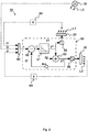
- FIG. 1 shows a lamp 10, which is designed in the present case as a floor lamp.
- this lamp 10 may also be a table lamp or a work light and be mounted for this purpose, for example, on a wall or a ceiling via suitable fastening means.
- FIG. 1 illustrated and exemplified trained as a floor lamp has a base 11, from which a holding rod 12 extends vertically upwards away.
- a lamp head 14 is held with a housing in which a first lamp 20 and a second lamp 30 are arranged.
- the first light-emitting means 20 may be any type of light-emitting means, in particular also an LED light-emitting means and is intended to directly illuminate an object 100, which may be a person or a workstation or the like.
- the first luminous means 20 emits a quantity of light L 1 .
- a second light source 30 which may also be one or more LED.
- this second light-emitting means 30 is arranged within the lamp head 14 in such a way that it emits light directed away from the object 100.
- the amount of light emitted by this second illuminant 30 is designated by the reference symbol L 2 .
- the lamp 10 has a control device 50, which is arranged in the illustrated embodiment within the lamp head 14.
- This control device 50 serves to switch on and off the first lighting means 20 and the second lighting means 30 and also to adjust their brightness in each case.
- the control device 50 with in FIG. 1 not shown lines with the first lamp 20 and the second lamp 30 in contact.
- the luminaire 10 has a light sensor 60 and a further sensor 70 for presence detection of an object entering the sensitivity range of the sensor 70, in particular a person.
- the sensors 60 and 70 are for this purpose in communication with the control device.
- the lamp 10 also has a suitable power supply device, the better clarity in FIG. 1 but has been omitted.
- FIG. 2 shows a block diagram of the individual components, as shown in the in FIG. 1 illustrated lamp 10 and in particular in the control device 50 are present.
- the already known reference numerals stand for the same parts.
- the lamp 10 has the control device 50, to which the input side of the light sensor 60 is connected. On the output side, the control device 50 on the one hand with the first lighting means 20 and on the other hand with the second lighting means 30 in connection.
- the first light emitting means 20 is turned on and an amount of light L 1 irradiates so, a portion of this light quantity L 1 as a reduced amount of light L 1 to the light sensor 60.
- This feedback of the amount of light L 1 to the light sensor 60 is labeled with the feedback path 62.
- losses which are caused for example by the medium air, in which the lamp 10 is.
- the attenuation of the light L 1 emitted by the first luminous means 20 is significantly higher than in room conditions which have clear air conditions.
- a similar feedback path 64 is given from the second illuminant 30 to the light sensor 60.
- the second luminous means 30 emits a quantity of light L 2 , which reaches the sensor 60 as a quantity of light l 2 .
- This attenuation factor can be considerable because the second illuminant 30 is intended to emit light only indirectly.
- the light sensor 60 can also reach a quantity of light l 3 originating from an extraneous light source 35 which emits a quantity of light L 3 .
- an extraneous light source can either be a different light or extraneous light which, for example, reaches the light sensor 60 via a door or a window.
- This total amount of light l at the light sensor 60 is supplied to the control device 50.
- the control device 50 has a control device 51 which is connected to an output of a subtractor 52.
- a first input of the subtractor 52 is supplied with a signal representative of the total amount of light l.
- signal l 2 ' is supplied, which corresponds to a calculated value for that amount of light l 2 , as it is present at the light sensor 60 and is caused by the second light source 30. This second signal l 2 'is subtracted from the total amount of light l in the subtractor 52.
- the input of the control device 51 is supplied with a signal l 1 ', which consists of the total amount of light l minus the calculated value l 2 '.
- the control device 51 determines from this input signal l 1 'an actuating signal y 1 at its output, which is used via a transducer 55 as a manipulated variable for the brightness of the first light-emitting means 20.
- the output signal y 1 is further supplied to an adder 53 and that at a first input.
- a signal ⁇ y is supplied to provide from the sum of both signals a manipulated variable y 2 , which is provided via a second converter 56 for controlling the brightness of the second illuminant 30.
- the control signal ⁇ y can be predetermined arbitrarily.
- the setting signal ⁇ y may have a value of -0.5 to always ensure that the second light emitting means 30 illuminates at half brightness compared to the brightness of the first lighting means 20th
- control signal y 2 is multiplied by a factor R m to give the value l2 '.
- R m is a so-called space reflection factor and thus a measure of how much light quantity l 2 emitted at the light sensor 60 from the second one of the lamps 30 light quantity L 2 arrives.
- This spatial reflection factor R m can be varied by the control device 50.
- this spatial reflection factor R m is multiplied by the control device 50 during operation of the luminaire with the value y 2 , in order then-when the first luminous means 20 is switched on-to give the mentioned value l 2 'by calculation.
- this value R m can always be corrected by the control device 50 by switching on the luminaire 10 when the first luminous means 20 is switched on, the second luminous means 30 being switched on a little later, for example by a few seconds. It can then be concluded that the proportion of that light which comes from the second light-emitting means 20 at the light sensor 60.
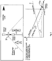
- FIG. 3 shows the typical characteristic curve of a lamp, as stored for example in the control device 51.
- the characteristic curves for the manipulated variables y 1 and y 2 are shown by way of example as linear characteristic curves on a logarithmic scale as a function of the value recorded by the light sensor 60 for the total amount of light 1
- FIG. 3 embodiment of the characteristic that the second lighting means is always less brightly lit by a factor of 0.3 as the first light emitting means 20, ⁇ y shown is therefore 0.3.
- a turn-on threshold E and a turn-off threshold A is set within the control device to turn off the light 10 when it is detected by the controller 50 that the turn-off threshold A is below the setting signal y 1 and the lamp 10 is turned on, if this actuating signal y 1 exceeds the switch-on threshold E.
- FIG. 5 shows the case that high external light is present in the detection range of the light sensor. However, the lamp 10 remains turned on, because the detected within the control device 50 light value l 1 is still above the switch-off threshold A. As in FIG. 5 however, in this case, the second illuminating means 30 for indirect lighting is only lit to a minimum value L 2min .
Claims (17)
- Procédé de gestion d'une lampe (10) comprenant un premier élément de lampe (20) permettant un éclairage direct et un second élément de lampe (30) permettant un éclairage indirect d'un objet (100) ainsi qu'un dispositif de commande (50) permettant de commander le premier élément de lampe (20) et le second élément de lampe (30) séparément l'un de l'autre, la lampe (10) comprenant au moins un capteur de lumière (60) monté sur celle-ci et permettant de détecter la quantité totale de lumière (l) dans la zone de ce capteur de lumière (60), y compris toute lumière étrangère qui y est présente, et le capteur de lumière (60) étant en liaison avec le dispositif de commande (50),
caractérisé en ce qu'il comprend les étapes suivantes :- le capteur de lumière (60) détecte la quantité totale de lumière (l),- le dispositif de commande (50) calcule la quantité de lumière indirecte (l2') émise par le second élément de lampe (30) et arrivant sur le capteur de lumière (60),- le dispositif de commande soustrait la quantité de lumière indirecte (l2') de la quantité de lumière totale (l) détectée pour déterminer la quantité de lumière directe (l1) émise par le premier élément de lampe (20), ainsi que la lumière étrangère, le cas échéant présente sur le capteur de lumière (60),- le dispositif de commande commande la lampe (10) en fonction des résultats de la soustraction. - Procédé conforme à la revendication 1,
caractérisé en ce que
le dispositif de commande (50) comprend un dispositif de régulation (51) qui, à partir de la quantité de lumière totale (l) détectée par le capteur de lumière (60), déduction faite de la quantité de lumière indirecte (l2') calculée, fournit un signal de sortie (y1) pour commander la luminosité du premier élément de lampe (20). - Procédé conforme à la revendication 2,
caractérisé en ce qu'
une valeur positive ou négative (Δy) est déduit du premier signal de sortie (y1) pour commander la luminosité du second élément de lampe (30) avec un second signal de sortie (y2) obtenu à partir de celle-ci. - Procédé conforme à la revendication 3,
caractérisé en ce que
le second signal de sortie (y2) est multiplié par un facteur (Rm) et ce résultat correspond à la quantité de lumière (l2') calculée qui est délivrée par le second élément de lampe (30) et est détectée au niveau du capteur de lumière (60). - Procédé conforme à la revendication 4,
caractérisé en ce que
le facteur (Rm) est un facteur de réflexion spatiale et indique par le calcul dans quelle mesure, la quantité de lumière indirecte (L2) délivrée par le second élément de lame (30) parvient au capteur de lumière (60). - Procédé conforme à la revendication 5,
caractérisé en ce que
le facteur de réflexion spatiale (Rm) est déterminé en ne commutant et coupant que le second élément de lampe (30) dans un mode de calibrage initial de la lampe (10), et, le facteur de réflexion spatiale (Rm) est déterminé à partir de la différence entre les quantités de lumière détectées par le capteur de lumière (60) et la connaissance de la hauteur d'une autre valeur de réglage de sortie du facteur de réflexion spatiale (Rm). - Procédé conforme à la revendication 5,
caractérisé en ce qu'
un ensemble de cycles de commutation et de coupure du second élément de lampe (30) est effectué, et on en déduit par le calcul, une valeur moyenne des facteurs de réflexion spatiale (Rm). - Procédé conforme à la revendication 5, 6 ou 7
caractérisé en ce que
le facteur de réflexion spatiale (Rm) est obtenu en commutant de façon décalée dans le temps le premier élément de lampe (20) puis le second élément de lampe (30), et le facteur de réflexion spatiale (Rm) préalablement déterminé est corrigé à partir de la différence des quantités de lumière ainsi détectées par le capteur de lumière (60). - Procédé conforme à la revendication 8,
caractérisé en ce que
la commutation décalée dans le temps du premier élément de lampe (20) et du second élément de lampe (30) s'effectue à l'échelle de la seconde. - Procédé conforme à l'une des revendications précédentes,
caractérisé en ce que
l'adaptation du facteur de réflexion spatiale (Rm) est effectuée dynamiquement. - Procédé conforme à l'une des revendications 1 à 10,
caractérisé en ce que
le second élément de lampe (30) destiné à la lumière indirecte (L2) est toujours coupé avec le premier élément de lampe (20) destiné à la lumière directe (L1). - Procédé conforme à l'une des revendications précédentes,
caractérisé en ce que
le second élément de lampe (30) destiné à la lumière indirecte (L2) éclaire au moins avec une valeur minimum (L2min) lorsque le premier élément de lampe (20) est commuté, à l'exception d'une durée destinée à permettre une commutation du second élément de lampe (30). - Procédé conforme à l'une des revendications précédentes,
caractérisé en ce que
la lampe (10) comporte un capteur (70) de reconnaissance de présence, et, en cas de reconnaissance de la présence d'une personne qui se déplace, la lampe (10) est commutée dans la mesure où le rapport de luminosité le nécessite en raison de la situation d'éclairage. - Procédé conforme à l'une des revendications précédentes,
caractérisé en ce que
le premier élément de lampe (20) et également le second élément de lampe (30) sont coupés lorsqu'une valeur de réglage interne (y1) de la proportion de lumière directe passe au-dessous d'un seuil de coupure (A) dans le dispositif de commande (50). - Procédé conforme à l'une des revendications 1 à 14,
caractérisé en ce qu'
il est mis en oeuvre pour gérer des lampes de travail et/ou des lampadaires, et ainsi pour l'éclairage spatial. - Procédé conforme à l'une des revendications 1 à 15,
caractérisé en ce que
le premier élément de lampe (20) et/ou le second élément de lampe (30) est(sont) formé(s) par un(plusieurs) corps lumineux, en particulier par une (plusieurs) LED. - Lampe (10) comprenant un premier élément de lampe (20) destiné à un éclairage direct et un second élément de lampe (30) destiné à un éclairage indirect d'un objet (100) ainsi qu'une installation de commande (50) permettant de commander le premier élément de lampe (20) et le second élément de lampe (30) indépendamment l'un de l'autre, la lampe (10) comportant au moins un capteur de lumière (60) monté sur cette lampe (10) pour détecter la quantité de lumière totale (l) dans la zone du capteur de lumière (60), y compris la lumière étrangère éventuellement présente, le capteur de lumière (60) étant relié au dispositif de commande (50),
caractérisée en ce que
le dispositif de commande (50) comporte des moyens permettant de soustraire de la quantité de lumière totale (l) détectée par le capteur de lumière (60) une quantité de lumière calculée (l2') de la quantité de lumière indirecte (l2) émise par le second élément de lampe (30) et arrivant sur le capteur de lumière (60), et ainsi de commander la lampe (10), en particulier de la commuter ou de la couper uniquement conformément à la quantité de lumière directe (l1) arrivant sur le capteur de lumière (60) et émise par le premier élément de lampe (20) et à la lumière étrangère (l3) éventuellement présente au niveau du capteur de lumière (60).
Priority Applications (4)
| Application Number | Priority Date | Filing Date | Title |
|---|---|---|---|
| EP13167676.9A EP2804443B1 (fr) | 2013-05-14 | 2013-05-14 | Procédé destiné au fonctionnement d'une lampe |
| US14/203,789 US9215774B2 (en) | 2013-05-14 | 2014-03-11 | Method for operating a lamp |
| IN744DE2014 IN2014DE00744A (fr) | 2013-05-14 | 2014-03-13 | |
| CN201410203337.2A CN105101512B (zh) | 2013-05-14 | 2014-05-14 | 操作灯的方法 |
Applications Claiming Priority (1)
| Application Number | Priority Date | Filing Date | Title |
|---|---|---|---|
| EP13167676.9A EP2804443B1 (fr) | 2013-05-14 | 2013-05-14 | Procédé destiné au fonctionnement d'une lampe |
Publications (2)
| Publication Number | Publication Date |
|---|---|
| EP2804443A1 EP2804443A1 (fr) | 2014-11-19 |
| EP2804443B1 true EP2804443B1 (fr) | 2017-06-28 |
Family
ID=48444144
Family Applications (1)
| Application Number | Title | Priority Date | Filing Date |
|---|---|---|---|
| EP13167676.9A Not-in-force EP2804443B1 (fr) | 2013-05-14 | 2013-05-14 | Procédé destiné au fonctionnement d'une lampe |
Country Status (4)
| Country | Link |
|---|---|
| US (1) | US9215774B2 (fr) |
| EP (1) | EP2804443B1 (fr) |
| CN (1) | CN105101512B (fr) |
| IN (1) | IN2014DE00744A (fr) |
Families Citing this family (7)
| Publication number | Priority date | Publication date | Assignee | Title |
|---|---|---|---|---|
| CH711000A1 (de) * | 2015-04-28 | 2016-10-31 | Iart Lab Gmbh | Leuchteneinrichtung und Verfahren zur Steuerung einer Leuchteneinrichtung. |
| DE102015115701A1 (de) * | 2015-09-17 | 2017-03-23 | PERFORMANCE IN LIGHTING GmbH | Leuchte |
| EP3363269A1 (fr) | 2015-10-13 | 2018-08-22 | Philips Lighting Holding B.V. | Éclairage de corniche |
| CH712086B1 (de) * | 2016-02-25 | 2018-06-29 | Alteme Licht Ag | Speicherprogrammierbare Steuerungseinheit zur tageslichtabhängigen Steuerung einer zugehörigen Stehlampe. |
| CN106016020B (zh) * | 2016-05-23 | 2019-05-24 | 苏州佳世达电通有限公司 | 灯具及其亮度调整方法 |
| JP6771147B2 (ja) * | 2016-06-22 | 2020-10-21 | パナソニックIpマネジメント株式会社 | 浴光システム及び携帯端末 |
| DE102017205449A1 (de) * | 2017-03-30 | 2018-10-04 | Zumtobel Lighting Gmbh | Leuchte |
Family Cites Families (11)
| Publication number | Priority date | Publication date | Assignee | Title |
|---|---|---|---|---|
| US9955551B2 (en) * | 2002-07-12 | 2018-04-24 | Yechezkal Evan Spero | Detector controlled illuminating system |
| CN101164381B (zh) * | 2005-04-22 | 2011-07-06 | 皇家飞利浦电子股份有限公司 | 用于照明控制的方法及系统 |
| KR101618582B1 (ko) * | 2007-04-20 | 2016-05-09 | 코닌클리케 필립스 엔.브이. | 감지에 사용되는 led를 갖는 조명 장치 |
| EP2319277A2 (fr) * | 2008-07-23 | 2011-05-11 | Koninklijke Philips Electronics N.V. | Système d'éclairage présentant une adaptation automatique au niveau de lumière du jour |
| US8324817B2 (en) * | 2008-10-24 | 2012-12-04 | Ilumisys, Inc. | Light and light sensor |
| DE102009016753A1 (de) | 2009-04-07 | 2010-10-14 | Zumtobel Lighting Gmbh | Anordnung zur Raumbeleuchtung |
| US8624505B2 (en) * | 2010-05-28 | 2014-01-07 | Tsmc Solid State Lighting Ltd. | Light color and intensity adjustable LED |
| DE102010031428A1 (de) | 2010-07-16 | 2012-01-19 | Zumtobel Lighting Gmbh | Leuchte |
| US20130229115A1 (en) * | 2010-11-11 | 2013-09-05 | Ashish Vijay Pandharipande | Methods for Disaggregated Sensing of Artificial Light and Daylight Distribution |
| AU2012332206B2 (en) * | 2011-11-03 | 2016-02-04 | Osram Sylvania Inc. | Methods, systems, and apparatus for intelligent lighting |
| JP6108150B2 (ja) * | 2012-07-10 | 2017-04-05 | 東芝ライテック株式会社 | 照明制御システム |
-
2013
- 2013-05-14 EP EP13167676.9A patent/EP2804443B1/fr not_active Not-in-force
-
2014
- 2014-03-11 US US14/203,789 patent/US9215774B2/en not_active Expired - Fee Related
- 2014-03-13 IN IN744DE2014 patent/IN2014DE00744A/en unknown
- 2014-05-14 CN CN201410203337.2A patent/CN105101512B/zh not_active Expired - Fee Related
Also Published As
| Publication number | Publication date |
|---|---|
| US20140339989A1 (en) | 2014-11-20 |
| CN105101512A (zh) | 2015-11-25 |
| US9215774B2 (en) | 2015-12-15 |
| CN105101512B (zh) | 2018-01-30 |
| IN2014DE00744A (fr) | 2015-06-19 |
| EP2804443A1 (fr) | 2014-11-19 |
Similar Documents
| Publication | Publication Date | Title |
|---|---|---|
| EP2804443B1 (fr) | Procédé destiné au fonctionnement d'une lampe | |
| EP3013123B1 (fr) | Système d'éclairage et procédé de commande correspondant | |
| EP3194938A1 (fr) | Dispositif d'éclairage et procédé permettant de faire fonctionner un éclairage | |
| DE102017111594A1 (de) | Beleuchtungssteuervorrichtung | |
| EP0563696B1 (fr) | Procédé et mode de couplage pour allumer et éteindre des sources lumineuses artificielles dans une pièce | |
| DE202014104294U1 (de) | LED-Lampervorrichtung zum Ausführen von verschiedenen Methoden zur Steuerung | |
| EP2372238A1 (fr) | Dispositif d'éclairage commandé par capteur de mouvement et dispositif de capteur de mouvement | |
| DE102010043013A1 (de) | Beleuchtungsvorrichtung und Verfahren zum Beleuchten | |
| WO2014016103A1 (fr) | Procédé et dispositif pour la détection de signaux optiques | |
| EP3211972B1 (fr) | Lampe de sol avec une unité commande programmable pour contrôler un éclairage direct et un éclairage indirect de façon économique et en fonction de la lumière ambiante | |
| DE202009009051U1 (de) | Leuchte | |
| DE19608224A1 (de) | Beleuchtungsanordnung mit von einem Lichtsensor gesteuerten Lichtquellen | |
| EP2408270B1 (fr) | Luminaire controllé par capteur | |
| DE102011075116A1 (de) | Raumbeleuchtungssystem zum beleuchten eines raums | |
| EP2902698B1 (fr) | Éclairage | |
| DE102015200133A1 (de) | Lichtsystem mit Anwesenheitserkennung von Personen | |
| DE102009019157A1 (de) | Verfahren und Vorrichtung zur Einstellung eines Helligkeitssollwerts einer Leuchte | |
| EP1227703B1 (fr) | Appareil et méthode pour commander un appareil d' éclairage | |
| DE19913760C2 (de) | Verfahren zur microprozessorgesteuerten Regelung der Beleuchtungsstärke eines Bereiches, der veränderlichem Fremdlicht (z. B. Tageslicht) und veränderbarem Beleuchtungskörperlicht ausgesetzt ist | |
| DE202014101163U1 (de) | LED-Leuchte mit Radar-Sensor | |
| CH702358B1 (de) | Leuchtreklame, insbesondere Leuchtbuchstabe. | |
| EP2375870A2 (fr) | Procédé et système de commande d'éclairage | |
| DE19639286C1 (de) | Verfahren zum Betreiben einer mit mindestens einem Sensor verbundenen Schaltungsvorrichtung für eine berührungslos steuerbare Sanitärarmatur | |
| EP2925096A2 (fr) | Procédé de commande d'une charge électrique ou d'un dispositif d'éclairage | |
| DE102010062826A1 (de) | Betätiger mit integriertem Bewegungsmelder |
Legal Events
| Date | Code | Title | Description |
|---|---|---|---|
| PUAI | Public reference made under article 153(3) epc to a published international application that has entered the european phase |
Free format text: ORIGINAL CODE: 0009012 |
|
| 17P | Request for examination filed |
Effective date: 20130514 |
|
| AK | Designated contracting states |
Kind code of ref document: A1 Designated state(s): AL AT BE BG CH CY CZ DE DK EE ES FI FR GB GR HR HU IE IS IT LI LT LU LV MC MK MT NL NO PL PT RO RS SE SI SK SM TR |
|
| AX | Request for extension of the european patent |
Extension state: BA ME |
|
| R17P | Request for examination filed (corrected) |
Effective date: 20150518 |
|
| RBV | Designated contracting states (corrected) |
Designated state(s): AL AT BE BG CH CY CZ DE DK EE ES FI FR GB GR HR HU IE IS IT LI LT LU LV MC MK MT NL NO PL PT RO RS SE SI SK SM TR |
|
| GRAP | Despatch of communication of intention to grant a patent |
Free format text: ORIGINAL CODE: EPIDOSNIGR1 |
|
| STAA | Information on the status of an ep patent application or granted ep patent |
Free format text: STATUS: GRANT OF PATENT IS INTENDED |
|
| INTG | Intention to grant announced |
Effective date: 20170201 |
|
| GRAS | Grant fee paid |
Free format text: ORIGINAL CODE: EPIDOSNIGR3 |
|
| GRAA | (expected) grant |
Free format text: ORIGINAL CODE: 0009210 |
|
| STAA | Information on the status of an ep patent application or granted ep patent |
Free format text: STATUS: THE PATENT HAS BEEN GRANTED |
|
| AK | Designated contracting states |
Kind code of ref document: B1 Designated state(s): AL AT BE BG CH CY CZ DE DK EE ES FI FR GB GR HR HU IE IS IT LI LT LU LV MC MK MT NL NO PL PT RO RS SE SI SK SM TR |
|
| REG | Reference to a national code |
Ref country code: GB Ref legal event code: FG4D Free format text: NOT ENGLISH |
|
| REG | Reference to a national code |
Ref country code: CH Ref legal event code: EP |
|
| REG | Reference to a national code |
Ref country code: CH Ref legal event code: NV Representative=s name: R.A. EGLI AND CO, PATENTANWAELTE, CH |
|
| REG | Reference to a national code |
Ref country code: AT Ref legal event code: REF Ref document number: 905863 Country of ref document: AT Kind code of ref document: T Effective date: 20170715 |
|
| REG | Reference to a national code |
Ref country code: IE Ref legal event code: FG4D Free format text: LANGUAGE OF EP DOCUMENT: GERMAN |
|
| REG | Reference to a national code |
Ref country code: DE Ref legal event code: R096 Ref document number: 502013007596 Country of ref document: DE |
|
| REG | Reference to a national code |
Ref country code: SE Ref legal event code: TRGR |
|
| REG | Reference to a national code |
Ref country code: NL Ref legal event code: FP |
|
| PG25 | Lapsed in a contracting state [announced via postgrant information from national office to epo] |
Ref country code: NO Free format text: LAPSE BECAUSE OF FAILURE TO SUBMIT A TRANSLATION OF THE DESCRIPTION OR TO PAY THE FEE WITHIN THE PRESCRIBED TIME-LIMIT Effective date: 20170928 Ref country code: HR Free format text: LAPSE BECAUSE OF FAILURE TO SUBMIT A TRANSLATION OF THE DESCRIPTION OR TO PAY THE FEE WITHIN THE PRESCRIBED TIME-LIMIT Effective date: 20170628 Ref country code: FI Free format text: LAPSE BECAUSE OF FAILURE TO SUBMIT A TRANSLATION OF THE DESCRIPTION OR TO PAY THE FEE WITHIN THE PRESCRIBED TIME-LIMIT Effective date: 20170628 Ref country code: GR Free format text: LAPSE BECAUSE OF FAILURE TO SUBMIT A TRANSLATION OF THE DESCRIPTION OR TO PAY THE FEE WITHIN THE PRESCRIBED TIME-LIMIT Effective date: 20170929 Ref country code: LT Free format text: LAPSE BECAUSE OF FAILURE TO SUBMIT A TRANSLATION OF THE DESCRIPTION OR TO PAY THE FEE WITHIN THE PRESCRIBED TIME-LIMIT Effective date: 20170628 |
|
| REG | Reference to a national code |
Ref country code: LT Ref legal event code: MG4D |
|
| PG25 | Lapsed in a contracting state [announced via postgrant information from national office to epo] |
Ref country code: RS Free format text: LAPSE BECAUSE OF FAILURE TO SUBMIT A TRANSLATION OF THE DESCRIPTION OR TO PAY THE FEE WITHIN THE PRESCRIBED TIME-LIMIT Effective date: 20170628 Ref country code: LV Free format text: LAPSE BECAUSE OF FAILURE TO SUBMIT A TRANSLATION OF THE DESCRIPTION OR TO PAY THE FEE WITHIN THE PRESCRIBED TIME-LIMIT Effective date: 20170628 Ref country code: BG Free format text: LAPSE BECAUSE OF FAILURE TO SUBMIT A TRANSLATION OF THE DESCRIPTION OR TO PAY THE FEE WITHIN THE PRESCRIBED TIME-LIMIT Effective date: 20170928 |
|
| PG25 | Lapsed in a contracting state [announced via postgrant information from national office to epo] |
Ref country code: CZ Free format text: LAPSE BECAUSE OF FAILURE TO SUBMIT A TRANSLATION OF THE DESCRIPTION OR TO PAY THE FEE WITHIN THE PRESCRIBED TIME-LIMIT Effective date: 20170628 Ref country code: SK Free format text: LAPSE BECAUSE OF FAILURE TO SUBMIT A TRANSLATION OF THE DESCRIPTION OR TO PAY THE FEE WITHIN THE PRESCRIBED TIME-LIMIT Effective date: 20170628 Ref country code: EE Free format text: LAPSE BECAUSE OF FAILURE TO SUBMIT A TRANSLATION OF THE DESCRIPTION OR TO PAY THE FEE WITHIN THE PRESCRIBED TIME-LIMIT Effective date: 20170628 Ref country code: RO Free format text: LAPSE BECAUSE OF FAILURE TO SUBMIT A TRANSLATION OF THE DESCRIPTION OR TO PAY THE FEE WITHIN THE PRESCRIBED TIME-LIMIT Effective date: 20170628 |
|
| PG25 | Lapsed in a contracting state [announced via postgrant information from national office to epo] |
Ref country code: PL Free format text: LAPSE BECAUSE OF FAILURE TO SUBMIT A TRANSLATION OF THE DESCRIPTION OR TO PAY THE FEE WITHIN THE PRESCRIBED TIME-LIMIT Effective date: 20170628 Ref country code: IS Free format text: LAPSE BECAUSE OF FAILURE TO SUBMIT A TRANSLATION OF THE DESCRIPTION OR TO PAY THE FEE WITHIN THE PRESCRIBED TIME-LIMIT Effective date: 20171028 Ref country code: ES Free format text: LAPSE BECAUSE OF FAILURE TO SUBMIT A TRANSLATION OF THE DESCRIPTION OR TO PAY THE FEE WITHIN THE PRESCRIBED TIME-LIMIT Effective date: 20170628 Ref country code: SM Free format text: LAPSE BECAUSE OF FAILURE TO SUBMIT A TRANSLATION OF THE DESCRIPTION OR TO PAY THE FEE WITHIN THE PRESCRIBED TIME-LIMIT Effective date: 20170628 |
|
| REG | Reference to a national code |
Ref country code: DE Ref legal event code: R097 Ref document number: 502013007596 Country of ref document: DE |
|
| PG25 | Lapsed in a contracting state [announced via postgrant information from national office to epo] |
Ref country code: DK Free format text: LAPSE BECAUSE OF FAILURE TO SUBMIT A TRANSLATION OF THE DESCRIPTION OR TO PAY THE FEE WITHIN THE PRESCRIBED TIME-LIMIT Effective date: 20170628 |
|
| PLBE | No opposition filed within time limit |
Free format text: ORIGINAL CODE: 0009261 |
|
| STAA | Information on the status of an ep patent application or granted ep patent |
Free format text: STATUS: NO OPPOSITION FILED WITHIN TIME LIMIT |
|
| REG | Reference to a national code |
Ref country code: FR Ref legal event code: PLFP Year of fee payment: 6 |
|
| 26N | No opposition filed |
Effective date: 20180329 |
|
| PG25 | Lapsed in a contracting state [announced via postgrant information from national office to epo] |
Ref country code: SI Free format text: LAPSE BECAUSE OF FAILURE TO SUBMIT A TRANSLATION OF THE DESCRIPTION OR TO PAY THE FEE WITHIN THE PRESCRIBED TIME-LIMIT Effective date: 20170628 |
|
| PG25 | Lapsed in a contracting state [announced via postgrant information from national office to epo] |
Ref country code: MT Free format text: LAPSE BECAUSE OF FAILURE TO SUBMIT A TRANSLATION OF THE DESCRIPTION OR TO PAY THE FEE WITHIN THE PRESCRIBED TIME-LIMIT Effective date: 20170628 |
|
| PG25 | Lapsed in a contracting state [announced via postgrant information from national office to epo] |
Ref country code: MC Free format text: LAPSE BECAUSE OF FAILURE TO SUBMIT A TRANSLATION OF THE DESCRIPTION OR TO PAY THE FEE WITHIN THE PRESCRIBED TIME-LIMIT Effective date: 20170628 |
|
| REG | Reference to a national code |
Ref country code: IE Ref legal event code: MM4A |
|
| PG25 | Lapsed in a contracting state [announced via postgrant information from national office to epo] |
Ref country code: IE Free format text: LAPSE BECAUSE OF NON-PAYMENT OF DUE FEES Effective date: 20180514 |
|
| PGFP | Annual fee paid to national office [announced via postgrant information from national office to epo] |
Ref country code: LU Payment date: 20190521 Year of fee payment: 7 Ref country code: NL Payment date: 20190521 Year of fee payment: 7 |
|
| PGFP | Annual fee paid to national office [announced via postgrant information from national office to epo] |
Ref country code: IT Payment date: 20190521 Year of fee payment: 7 |
|
| PGFP | Annual fee paid to national office [announced via postgrant information from national office to epo] |
Ref country code: BE Payment date: 20190521 Year of fee payment: 7 Ref country code: SE Payment date: 20190523 Year of fee payment: 7 |
|
| PGFP | Annual fee paid to national office [announced via postgrant information from national office to epo] |
Ref country code: GB Payment date: 20190523 Year of fee payment: 7 |
|
| REG | Reference to a national code |
Ref country code: DE Ref legal event code: R079 Ref document number: 502013007596 Country of ref document: DE Free format text: PREVIOUS MAIN CLASS: H05B0033080000 Ipc: H05B0045000000 |
|
| PG25 | Lapsed in a contracting state [announced via postgrant information from national office to epo] |
Ref country code: TR Free format text: LAPSE BECAUSE OF FAILURE TO SUBMIT A TRANSLATION OF THE DESCRIPTION OR TO PAY THE FEE WITHIN THE PRESCRIBED TIME-LIMIT Effective date: 20170628 |
|
| PG25 | Lapsed in a contracting state [announced via postgrant information from national office to epo] |
Ref country code: HU Free format text: LAPSE BECAUSE OF FAILURE TO SUBMIT A TRANSLATION OF THE DESCRIPTION OR TO PAY THE FEE WITHIN THE PRESCRIBED TIME-LIMIT; INVALID AB INITIO Effective date: 20130514 Ref country code: PT Free format text: LAPSE BECAUSE OF FAILURE TO SUBMIT A TRANSLATION OF THE DESCRIPTION OR TO PAY THE FEE WITHIN THE PRESCRIBED TIME-LIMIT Effective date: 20170628 |
|
| PG25 | Lapsed in a contracting state [announced via postgrant information from national office to epo] |
Ref country code: MK Free format text: LAPSE BECAUSE OF NON-PAYMENT OF DUE FEES Effective date: 20170628 Ref country code: CY Free format text: LAPSE BECAUSE OF FAILURE TO SUBMIT A TRANSLATION OF THE DESCRIPTION OR TO PAY THE FEE WITHIN THE PRESCRIBED TIME-LIMIT Effective date: 20170628 |
|
| PG25 | Lapsed in a contracting state [announced via postgrant information from national office to epo] |
Ref country code: AL Free format text: LAPSE BECAUSE OF FAILURE TO SUBMIT A TRANSLATION OF THE DESCRIPTION OR TO PAY THE FEE WITHIN THE PRESCRIBED TIME-LIMIT Effective date: 20170628 |
|
| REG | Reference to a national code |
Ref country code: NL Ref legal event code: MM Effective date: 20200601 |
|
| PG25 | Lapsed in a contracting state [announced via postgrant information from national office to epo] |
Ref country code: SE Free format text: LAPSE BECAUSE OF NON-PAYMENT OF DUE FEES Effective date: 20200515 |
|
| PG25 | Lapsed in a contracting state [announced via postgrant information from national office to epo] |
Ref country code: NL Free format text: LAPSE BECAUSE OF NON-PAYMENT OF DUE FEES Effective date: 20200601 |
|
| REG | Reference to a national code |
Ref country code: BE Ref legal event code: MM Effective date: 20200531 |
|
| GBPC | Gb: european patent ceased through non-payment of renewal fee |
Effective date: 20200514 |
|
| PG25 | Lapsed in a contracting state [announced via postgrant information from national office to epo] |
Ref country code: LU Free format text: LAPSE BECAUSE OF NON-PAYMENT OF DUE FEES Effective date: 20200514 |
|
| PG25 | Lapsed in a contracting state [announced via postgrant information from national office to epo] |
Ref country code: GB Free format text: LAPSE BECAUSE OF NON-PAYMENT OF DUE FEES Effective date: 20200514 |
|
| PG25 | Lapsed in a contracting state [announced via postgrant information from national office to epo] |
Ref country code: BE Free format text: LAPSE BECAUSE OF NON-PAYMENT OF DUE FEES Effective date: 20200531 |
|
| STAA | Information on the status of an ep patent application or granted ep patent |
Free format text: STATUS: NO OPPOSITION FILED WITHIN TIME LIMIT |
|
| PGFP | Annual fee paid to national office [announced via postgrant information from national office to epo] |
Ref country code: FR Payment date: 20210521 Year of fee payment: 9 Ref country code: DE Payment date: 20210625 Year of fee payment: 9 |
|
| PGFP | Annual fee paid to national office [announced via postgrant information from national office to epo] |
Ref country code: AT Payment date: 20210518 Year of fee payment: 9 Ref country code: CH Payment date: 20210525 Year of fee payment: 9 |
|
| PG25 | Lapsed in a contracting state [announced via postgrant information from national office to epo] |
Ref country code: IT Free format text: LAPSE BECAUSE OF NON-PAYMENT OF DUE FEES Effective date: 20200514 |
|
| REG | Reference to a national code |
Ref country code: DE Ref legal event code: R119 Ref document number: 502013007596 Country of ref document: DE |
|
| REG | Reference to a national code |
Ref country code: CH Ref legal event code: PL |
|
| REG | Reference to a national code |
Ref country code: AT Ref legal event code: MM01 Ref document number: 905863 Country of ref document: AT Kind code of ref document: T Effective date: 20220514 |
|
| PG25 | Lapsed in a contracting state [announced via postgrant information from national office to epo] |
Ref country code: LI Free format text: LAPSE BECAUSE OF NON-PAYMENT OF DUE FEES Effective date: 20220531 Ref country code: CH Free format text: LAPSE BECAUSE OF NON-PAYMENT OF DUE FEES Effective date: 20220531 Ref country code: AT Free format text: LAPSE BECAUSE OF NON-PAYMENT OF DUE FEES Effective date: 20220514 |
|
| PG25 | Lapsed in a contracting state [announced via postgrant information from national office to epo] |
Ref country code: FR Free format text: LAPSE BECAUSE OF NON-PAYMENT OF DUE FEES Effective date: 20220531 |
|
| PG25 | Lapsed in a contracting state [announced via postgrant information from national office to epo] |
Ref country code: DE Free format text: LAPSE BECAUSE OF NON-PAYMENT OF DUE FEES Effective date: 20221201 |