EP2803969A1 - Abgasanalysesystem, Abgassammelvorrichtung und Abgasleckerkennungsverfahren - Google Patents
Abgasanalysesystem, Abgassammelvorrichtung und Abgasleckerkennungsverfahren Download PDFInfo
- Publication number
- EP2803969A1 EP2803969A1 EP14001730.2A EP14001730A EP2803969A1 EP 2803969 A1 EP2803969 A1 EP 2803969A1 EP 14001730 A EP14001730 A EP 14001730A EP 2803969 A1 EP2803969 A1 EP 2803969A1
- Authority
- EP
- European Patent Office
- Prior art keywords
- exhaust gas
- gas collecting
- collecting
- exhaust
- detecting
- Prior art date
- Legal status (The legal status is an assumption and is not a legal conclusion. Google has not performed a legal analysis and makes no representation as to the accuracy of the status listed.)
- Withdrawn
Links
Images

Classifications
-
- G—PHYSICS
- G01—MEASURING; TESTING
- G01N—INVESTIGATING OR ANALYSING MATERIALS BY DETERMINING THEIR CHEMICAL OR PHYSICAL PROPERTIES
- G01N1/00—Sampling; Preparing specimens for investigation
- G01N1/02—Devices for withdrawing samples
- G01N1/22—Devices for withdrawing samples in the gaseous state
- G01N1/2247—Sampling from a flowing stream of gas
- G01N1/2252—Sampling from a flowing stream of gas in a vehicle exhaust
-
- F—MECHANICAL ENGINEERING; LIGHTING; HEATING; WEAPONS; BLASTING
- F01—MACHINES OR ENGINES IN GENERAL; ENGINE PLANTS IN GENERAL; STEAM ENGINES
- F01N—GAS-FLOW SILENCERS OR EXHAUST APPARATUS FOR MACHINES OR ENGINES IN GENERAL; GAS-FLOW SILENCERS OR EXHAUST APPARATUS FOR INTERNAL-COMBUSTION ENGINES
- F01N11/00—Monitoring or diagnostic devices for exhaust-gas treatment apparatus
-
- G—PHYSICS
- G01—MEASURING; TESTING
- G01M—TESTING STATIC OR DYNAMIC BALANCE OF MACHINES OR STRUCTURES; TESTING OF STRUCTURES OR APPARATUS, NOT OTHERWISE PROVIDED FOR
- G01M3/00—Investigating fluid-tightness of structures
-
- G—PHYSICS
- G01—MEASURING; TESTING
- G01M—TESTING STATIC OR DYNAMIC BALANCE OF MACHINES OR STRUCTURES; TESTING OF STRUCTURES OR APPARATUS, NOT OTHERWISE PROVIDED FOR
- G01M3/00—Investigating fluid-tightness of structures
- G01M3/02—Investigating fluid-tightness of structures by using fluid or vacuum
- G01M3/04—Investigating fluid-tightness of structures by using fluid or vacuum by detecting the presence of fluid at the leakage point
-
- G—PHYSICS
- G01—MEASURING; TESTING
- G01N—INVESTIGATING OR ANALYSING MATERIALS BY DETERMINING THEIR CHEMICAL OR PHYSICAL PROPERTIES
- G01N1/00—Sampling; Preparing specimens for investigation
- G01N1/02—Devices for withdrawing samples
- G01N1/22—Devices for withdrawing samples in the gaseous state
- G01N1/26—Devices for withdrawing samples in the gaseous state with provision for intake from several spaces
-
- G—PHYSICS
- G01—MEASURING; TESTING
- G01M—TESTING STATIC OR DYNAMIC BALANCE OF MACHINES OR STRUCTURES; TESTING OF STRUCTURES OR APPARATUS, NOT OTHERWISE PROVIDED FOR
- G01M15/00—Testing of engines
- G01M15/04—Testing internal-combustion engines
- G01M15/10—Testing internal-combustion engines by monitoring exhaust gases or combustion flame
- G01M15/102—Testing internal-combustion engines by monitoring exhaust gases or combustion flame by monitoring exhaust gases
-
- G—PHYSICS
- G01—MEASURING; TESTING
- G01N—INVESTIGATING OR ANALYSING MATERIALS BY DETERMINING THEIR CHEMICAL OR PHYSICAL PROPERTIES
- G01N1/00—Sampling; Preparing specimens for investigation
- G01N1/02—Devices for withdrawing samples
- G01N1/22—Devices for withdrawing samples in the gaseous state
- G01N1/2247—Sampling from a flowing stream of gas
- G01N1/2252—Sampling from a flowing stream of gas in a vehicle exhaust
- G01N2001/2255—Sampling from a flowing stream of gas in a vehicle exhaust with dilution of the sample
-
- G—PHYSICS
- G01—MEASURING; TESTING
- G01N—INVESTIGATING OR ANALYSING MATERIALS BY DETERMINING THEIR CHEMICAL OR PHYSICAL PROPERTIES
- G01N33/00—Investigating or analysing materials by specific methods not covered by groups G01N1/00 - G01N31/00
- G01N33/0004—Gaseous mixtures, e.g. polluted air
- G01N33/0009—General constructional details of gas analysers, e.g. portable test equipment
- G01N33/0011—Sample conditioning
- G01N33/0018—Sample conditioning by diluting a gas
-
- G—PHYSICS
- G01—MEASURING; TESTING
- G01N—INVESTIGATING OR ANALYSING MATERIALS BY DETERMINING THEIR CHEMICAL OR PHYSICAL PROPERTIES
- G01N33/00—Investigating or analysing materials by specific methods not covered by groups G01N1/00 - G01N31/00
- G01N33/0004—Gaseous mixtures, e.g. polluted air
- G01N33/0009—General constructional details of gas analysers, e.g. portable test equipment
- G01N33/0062—General constructional details of gas analysers, e.g. portable test equipment concerning the measuring method or the display, e.g. intermittent measurement or digital display
- G01N33/0063—General constructional details of gas analysers, e.g. portable test equipment concerning the measuring method or the display, e.g. intermittent measurement or digital display using a threshold to release an alarm or displaying means
-
- G—PHYSICS
- G01—MEASURING; TESTING
- G01N—INVESTIGATING OR ANALYSING MATERIALS BY DETERMINING THEIR CHEMICAL OR PHYSICAL PROPERTIES
- G01N33/00—Investigating or analysing materials by specific methods not covered by groups G01N1/00 - G01N31/00
- G01N33/0004—Gaseous mixtures, e.g. polluted air
- G01N33/0009—General constructional details of gas analysers, e.g. portable test equipment
- G01N33/0073—Control unit therefor
- G01N33/0075—Control unit therefor for multiple spatially distributed sensors, e.g. for environmental monitoring
Definitions
- the present invention relates to an exhaust gas analysis system and an exhaust gas collecting device for collecting exhaust gas discharged from an internal combustion engine or an exhaust gas leak detecting method for detecting a leak of exhaust gas discharged from an internal combustion engine.
- an exhaust gas analysis device including an open type exhaust gas collecting part (referred to as "open type collecting part” hereinafter) as disclosed in, for example, Patent Literature 1.
- This exhaust gas analysis device includes: an open type collecting part for sucking exhaust gas discharged from an exhaust pipe of a vehicle and sucking air around the exhaust pipe; a flow passage in which mixed gas obtained by mixing the exhaust gas and the air sucked from this open type collecting part flows; and a measuring part installed in this flow passage and measuring a concentration of a predetermined measurement component contained in the mixed gas.
- Patent Literature 1 U.S. Pat. No. 5907109
- Patent Literature 1 since it is not possible to confirm whether or not the exhaust gas leaks, it is not known whether the exhaust gas discharged from the internal combustion engine can be collected by the open type collecting part without a leak and therefore it is not possible to ensure reliability for the test results of the exhaust gas test.
- the present invention has been made in view of the above problems, and an essential object thereof is to detect exhaust gas leaking from a space between an exhaust pipe and an open type exhaust gas collecting part in an exhaust gas collecting device using the open type exhaust gas collecting part.
- an exhaust gas analysis system includes: an exhaust gas collecting device for collecting exhaust gas from an exhaust pipe in which the exhaust gas discharged from an internal combustion engine flows; and gas analysis equipment for analyzing the exhaust gas collected by the exhaust gas collecting device.
- the exhaust gas collecting device includes: an exhaust gas collecting part which is provided at an exhaust gas discharge port of the exhaust pipe, having an exhaust gas collecting port that is larger than the exhaust gas discharge port, for collecting air around the exhaust gas discharge port together with the exhaust gas discharged from the exhaust gas discharge port; a main flow passage which is connected to the exhaust gas collecting part and in which the exhaust gas and the air collected from the exhaust gas collecting part flow; and an exhaust gas detecting mechanism for continuously detecting a predetermined component contained in the exhaust gas in the vicinity of the exhaust gas collecting port in the exhaust gas collecting part.
- the exhaust gas detecting mechanism since the exhaust gas detecting mechanism is provided, it is possible to detect whether the exhaust gas is leaked between the exhaust pipe and the exhaust gas collecting part by confirming the detection result of the exhaust gas detecting mechanism. Moreover, since the exhaust gas detecting mechanism is provided in the vicinity of the exhaust gas collecting port, it is possible to prevent that it becomes difficult for the exhaust gas detecting mechanism to detect the predetermined component contained in the exhaust gas because of excessive dilution of the leaked exhaust gas with the air around the exhaust pipe.
- the exhaust gas detecting mechanism is provided for continuously detecting the predetermined component, the leak of the exhaust gas can be detected in real time.
- the exhaust gas detecting mechanism includes: a detection sampling part for collecting gas in the vicinity of the exhaust gas collecting port of the exhaust gas collecting part; and a leak detecting part for detecting a concentration of the predetermined component contained in the exhaust gas in the gas collected by the detection sampling part, and that the detection sampling part includes a plurality of sampling pipes in the vicinity of the exhaust gas collecting port.
- the exhaust gas detecting mechanism is adapted to measure carbon dioxide or carbon monoxide. Since the carbon dioxide or carbon monoxide contained in the exhaust gas is higher in concentration compared to carbon dioxide or carbon monoxide contained in the air and exhibits a large difference in concentration, it becomes easy to detect the leak of the exhaust gas.
- a throttle surface for connecting between the exhaust gas collecting port and the opening in cross section of the main flow passage is to be provided in an inner peripheral surface of the exhaust gas collecting part.
- this throttle surface has a flat surface facing the exhaust gas collecting port, there is a possibility that the exhaust gas and air discharged from the exhaust pipe toward the main flow passage may rebound on this flat surface and leak to the outside from a portion between the exhaust gas collecting part and the exhaust pipe.
- the exhaust gas collecting part has a taper surface with an opening in cross section thereof gradually decreases toward a side of the connecting portion of the main flow passage from a side of the exhaust gas collecting port in the inner peripheral surface of the exhaust gas collecting part.
- the exhaust gas analysis system of the present invention further includes a constant flow mechanism provided on the main flow passage for maintaining a flow rate of fluid flowing in the main flow passage constant and further includes a dilution gas flow passage provided on the main flow passage and connected to an upstream side of the constant flow mechanism for introducing dilution gas into the main flow passage.
- the flow rate of the air collected from the exhaust gas collecting part can be adjusted by adjusting the flow rate of the dilution gas introduced from the dilution gas flow passage.
- the flow rate of the air to be collected by the exhaust gas collecting part can be increased by decreasing the flow rate of the dilution gas flowing in the dilution gas introducing flow passage, and thus the leak of the exhaust gas can be eliminated.
- the leak of the exhaust gas can be eliminated without changing the flow rate of the fluid flowing in the main flow passage by the constant flow mechanism, it is possible to accurately perform the exhaust gas analysis without largely varying a dilution ratio of the exhaust gas.
- an exhaust gas leak detecting method of an exhaust gas analysis system includes exhaust gas analysis equipment for analyzing exhaust gas collected by an exhaust gas collecting device for collecting exhaust gas from an exhaust pipe in which the exhaust gas discharged from an internal combustion engine flows.
- the exhaust gas collecting device includes: an exhaust gas collecting part which is provided at an exhaust gas discharge port of the exhaust pipe in which the exhaust gas flows and has an exhaust gas collecting port that is larger than the exhaust gas discharge port, and an exhaust gas detecting mechanism for detecting a predetermined component contained in the exhaust gas in the vicinity of the exhaust gas collecting port in the exhaust gas collecting part, thereby detecting a leak of the exhaust gas using detection results detected by the exhaust gas detecting mechanism.
- the present invention configured as described above, it is possible to detect the exhaust gas leaking from a portion between the exhaust pipe and the open type exhaust gas collecting part in collecting the exhaust gas using the open type exhaust gas collecting part.
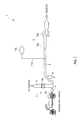
- the exhaust gas analysis system 1 in the present embodiment is a quantitative dilution analysis device (open type CVS) provided with an open type exhaust gas collecting device.
- This exhaust gas analysis system 1 is adapted to collect exhaust gas discharged from an exhaust pipe 100 of an internal combustion engine, for example, in an automobile or a motorcycle and dilute the collected exhaust gas with dilution gas such as air, and then a concentration of a predetermined component of the diluted exhaust gas is to be detected.
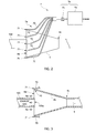
- the exhaust gas analysis system 1 of the present embodiment includes: an open type exhaust gas collecting part 4 for collecting the exhaust gas discharged from the exhaust pipe 100 and air around the exhaust pipe 100; and a main flow passage 5 which is connected to the exhaust gas collecting part 4 so that the exhaust gas and air collected from the exhaust gas collecting part 4 flow therein.
- the exhaust gas collecting part 4 is intended to be provided so as to be substantially opposite to an exhaust gas discharge port 100a of the exhaust pipe 100.
- This exhaust gas collecting part 4 has an exhaust gas collecting port 4a which is larger than the exhaust gas discharge port 100a and it is intended to collect the air around the exhaust gas discharge port 100a together with the exhaust gas discharged from the exhaust gas discharge port 100a.
- the exhaust gas collecting part 4 has a hollow circular tube shape and it includes the exhaust gas collecting port 4a having a circular open shape which is formed in an opening part 40 in an upstream side.
- This exhaust gas collecting port 4a is arranged so as to be substantially concentric with the exhaust gas discharge port 100a of the exhaust pipe 100.
- the main flow passage 5 is connected to an opening part in a downstream side of the exhaust gas collecting part 4.
- an inner peripheral surface of the exhaust gas collecting part 4 is formed as a taper surface 4b having an opening in cross section gradually decreasing from the exhaust gas collecting port 4a toward a connecting portion 4c which is connected to the main flow passage 5.
- the inner peripheral surface thereof is formed as the taper surface 4b.
- the main flow passage 5 has a dilution gas introducing flow passage 6 for introducing the dilution gas into the main flow passage 5; a mixing part 8 for stirring the exhaust gas, air and dilution gas to be mixed; and a constant flow mechanism 9 for keeping the flow rate of the fluid flowing in the main flow passage 5 constant, and these parts 6, 8 and 9 are arranged from the upstream side in this order.
- the dilution gas introducing flow passage 6 is connected to the main flow passage 5 for allowing the dilution gas such as air to flow into the main flow passage 5.
- a flow adjusting valve 6a is provided on the dilution gas introducing flow passage 6 in order that, for example, a user can appropriately vary a flow rate of the dilution gas.
- the mixing part 8 includes a cyclone which is provided in a downstream side of a confluence of the main flow passage 5 and the dilution gas introducing flow passage 6, and this cyclone is adapted to remove dusts and stir the exhaust gas and air to be mixed to thereby produce the mixed gas obtained by diluting the exhaust gas with the air.
- the air to be stirred and mixed with the exhaust gas by the mixing part 8 is the air collected by the exhaust gas collecting part 4 and the air that is the dilution gas introduced from the dilution gas introducing flow passage 6.
- the constant flow mechanism 9 is intended to control the flow rate so that the total flow rate of the mixed gas becomes constant flow rate and it is configured of a venture 10a that is composed of a critical flow venture (CFV) and a suction pump 10b such as a blower that is connected to a downstream of this venture 10a.
- a venture 10a that is composed of a critical flow venture (CFV) and a suction pump 10b such as a blower that is connected to a downstream of this venture 10a.
- CMV critical flow venture
- the mixed gas is sucked by the suction pump 10b and a pressure difference between the upstream side and the downstream side of the venture 10a is set to be a predetermined value or higher.
- the total flow rate of the mixed gas flowing in the main flow passage 5 is kept to be constant.
- the mixed gas sucked by the suction pump 10b is discharged to the outside.
- a sampling line 11a is connected to a portion between the mixing part 8 and the constant flow mechanism 9 in the main flow passage 5 for collecting a part of the mixed gas flowing in the main flow passage 5.
- Analysis equipment 11b is connected to this sampling line 11a for analyzing the mixed gas collected through the sampling line 11a.
- the analysis equipment 11b includes, for example, a collecting bag for accumulating the collected mixed gas. A concentration of a predetermined component contained in the mixed gas accumulated in this collecting bag is analyzed by an analyzer such as, for example, NDIR (non-dispersive infrared analyzer).
- an analyzer such as, for example, NDIR (non-dispersive infrared analyzer).
- the exhaust gas collecting part 4 of the present embodiment is provided with an exhaust gas detecting mechanism 7 for detecting a predetermined component contained in the exhaust gas for detecting a leak of the exhaust gas.
- the exhaust gas detecting mechanism 7 includes: a detection sampling part 7a for collecting gas in the vicinity of the exhaust gas collecting port 4a of the exhaust gas collecting part 4; and a leak detecting part 7b for detecting a concentration of a predetermined component contained in the exhaust gas in the gas collected by the detection sampling part 7a. Further, the leak detecting part 7b includes: a pump 7c for sampling the gas; and a detector 7d for detecting the gas component.
- the term "vicinity" implies any position where the exhaust gas leaking from the exhaust gas collecting port 4a can be collected in the exhaust gas collecting part 4, and, for example, an inner peripheral surface, an outer peripheral surface or a distal end surface of the opening portion 40 of the exhaust gas collecting part 4 where the exhaust gas collecting port 4a is formed, may be considered.
- the detection sampling part 7a is opened in the vicinity of the exhaust gas collecting port 4a and includes, for example, a flexible sampling tube 70.
- the sampling tube 70 has an opening end portion 71 forming an upstream side opening (sampling opening) that is provided on an outer peripheral surface of the opening portion 40 of the exhaust gas collecting part 4.
- an opening direction of the upstream side opening end portion 71 of the sampling tube 70 is the same direction as an opening direction of the exhaust gas collecting part 4 or an inclination direction of the taper surface 4b of the exhaust gas collecting part 4.
- the detection sampling part 7a samples the gas in the vicinity of the exhaust gas collecting port 4a by the sampling tube 70, the gas component detector 7d or the pump 7c which is provided in the upstream or downstream of the gas component detector 7d.
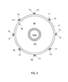
- the detection sampling part 7a of the present embodiment includes multiple sampling tubes 70 (i.e., eight tubes in Fig. 4 ) and the opening end portions 71 of the multiple sampling tubes 70 are provided at equal intervals in a circumferential direction so as to surround the opening portion 40 of the exhaust gas collecting port 4a.
- multiple sampling tubes 70 i.e., eight tubes in Fig. 4
- the opening end portions 71 of the multiple sampling tubes 70 are provided at equal intervals in a circumferential direction so as to surround the opening portion 40 of the exhaust gas collecting port 4a.
- the leak detecting part 7b is adapted to continuously measure a concentration of a predetermined component contained in the exhaust gas in the gas collected by the detection sampling part 7a.
- the leak detecting part 7b is composed of an exhaust gas analysis device that detects the concentration of the predetermined component by a non-dispersive infrared-ray absorbing method of applying, for example, infrared light emitted from an infrared light source to the gas collected from the detection sampling part 7a and using property of absorbing this infrared light by the predetermined component contained in the gas. Further, the leak detecting part 7b outputs the measured concentration to a display part such as a monitor.
- a user can detect whether the exhaust gas leaks from the exhaust gas collecting port 4a by comparing the measured concentration outputted to this display part to a predetermined threshold.
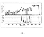
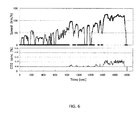
- Figs. 5 and 6 are test results showing the detected concentrations of CO gas and CO 2 gas when driving a test motorcycle in WMTC (Worldwide-harmonized Motorcycle Test Cycle) mode that is used in an official exhaust gas test where the discharge port 100a of the exhaust pipe 100 of the test motorcycle and the exhaust gas collecting port 4a of the exhaust gas collecting part 4 are disposed with a space of 5 cm while setting the suction quantity Q FNL of the suction pump 10b disposed in the main flow passage 5 to be 4 m 3 /min.
- WMTC Worldwide-harmonized Motorcycle Test Cycle
- Fig. 5 is the test result when the leak detecting part 7b detects CO as the predetermined component
- Fig. 6 is the test result when the leak detecting part 7b detects CO 2 as the predetermined component.
- CO is set to 10 ppm and CO 2 is set to 0.05% tentatively as the threshold for leak determination and it is determined that there is a possibility of the exhaust gas leaking when the measured concentration exceeds this threshold value.
- CO 2 as the predetermined component to be detected by the leak detecting part 7b of the exhaust gas detecting mechanism 7 in view of being able to detect a leak even in the case of a vehicle equipped with a three-way catalyst system.
- the exhaust gas collecting port 4a of the exhaust gas collecting part 4 is disposed in a predetermined collecting position with respect to the exhaust gas discharge port 100a of the exhaust pipe 100. Then, upon starting the suction pump 10b of the exhaust gas analysis system 1, the exhaust gas collecting port 4a collects the exhaust gas discharged from the exhaust gas discharge port 100a of the exhaust pipe 100 and collects the air around the exhaust gas discharge port 100a at the same time.
- the detection sampling part 7a in the exhaust gas collecting part 4 collects the gas in the vicinity of the exhaust gas collecting port 4a and introduces the collected gas into the leak detecting part 7b.
- the leak detecting part 7b detects the concentration of the predetermined component contained in the gas introduced from the detection sampling part 7a and outputs this concentration to such as, for example, a monitor. Then, the user compares this outputted concentration to the predetermined threshold and confirms whether or not the exhaust gas leaks.
- the exhaust gas detecting mechanism 7 since the exhaust gas detecting mechanism 7 is provided, by confirming the detection result of the exhaust gas detecting mechanism 7, it is possible to detect whether the exhaust gas leaks from a portion between the exhaust pipe 100 and the exhaust gas collecting part 4. Moreover, since the exhaust gas detecting mechanism 7 is provided in the vicinity of the exhaust gas collecting port 4a, in the case of using the open type exhaust gas collecting part 4, it is possible to prevent the exhaust gas from being excessively diluted by the air present around the exhaust pipe 100 and prevent that it becomes difficult for the exhaust gas detecting mechanism 7 to detect the predetermined component contained in the exhaust gas.
- the exhaust gas detecting mechanism 7 is provided for continuously detecting the predetermined component, the leak of the exhaust gas can be detected in real time.
- the detection sampling part 7a for collecting gas in the vicinity of the exhaust gas collecting port 4a of the exhaust gas collecting part 4 includes a plurality of the sampling pipes 70, it is possible to sample the gas at a plurality of points in the vicinity of the exhaust gas collecting port 4a and it is possible to perform the sampling of the gas accurately to detect the leak of the exhaust gas even in the case where s leaking location cannot be determined due to such as vibrations of the exhaust pipe 100.
- the multiple sampling tubes 70 are bundled to be a single tube and connected to the leak detecting part 7b, the number of parts can be reduced to simplify the device configuration compared to the case where the leak detecting parts 7b are respectively provided for the multiple sampling tubes 70.
- the taper surface is provided around the connecting portion 4c connected to the main flow passage 5 in the inner peripheral surface of the exhaust gas collecting part 4, even in the case where the exhaust gas and air discharged from the exhaust pipe 100 toward the main flow passage 5 rebound on the taper surface 4b, it is possible to facilitate the exhaust gas and air to flow into the main flow passage 5 without leaking to the outside from the portion between the exhaust gas collecting part 4 and the exhaust pipe 100.
- the flow rate of the air collected from the exhaust gas collecting part 4 can be adjusted by adjusting the flow rate of the dilution gas introduced from the dilution gas flow passage 6.
- the flow rate of the air to be collected by the exhaust gas collecting part 4 can be increased by decreasing the flow rate of the dilution gas flowing in the dilution gas introducing flow passage 6, and thus the leak of the exhaust gas can be eliminated.
- the leak of the exhaust gas can be eliminated without changing the flow rate of the fluid flowing in the main flow passage 5 by the constant flow mechanism 9, it is possible to accurately perform the exhaust gas analysis without largely varying a dilution ratio of the exhaust gas.
- the user in the case where the user confirms the concentration of the predetermined substance detected by the exhaust gas detecting mechanism 7 and determines that exhaust gas is leaking, the user can take actions for eliminating the leak of the exhaust gas by adjusting the positional relationship between the exhaust pipe 100 and the exhaust gas collecting part 4 or adjusting the flow rate of the dilution gas flowing in the dilution gas introducing flow passage 6 using the flow adjusting valve 6a. Therefore, the exhaust gas analysis can be accurately performed and it is possible to perform the test in conformance with a measuring method defined in such as the Road Vehicle Safety Standard or the international standards, and it is possible to ensure reliability for the test result of the exhaust gas test.
- the exhaust gas analysis system of the present embodiment may be configured such that, after collecting a part of the diluted exhaust gas from the main flow passage, the diluted gas is diluted again (two-stage dilution), and the two-stage-diluted exhaust gas is analyzed.
- the exhaust gas collecting device of the present embodiment is configured to collect the exhaust gas discharged from the exhaust pipe of the engine of such as a motorcycle or automobile driven by a chassis dynamometer, it may be configured, for example, to collect the exhaust gas discharged from the exhaust pipe of the engine driven by an engine dynamometer.
- the dilution gas introducing flow passage is provided, it is not necessary to provide the dilution gas introducing flow passage.
- the air to be mixed with the exhaust gas by the mixing part is only the air collected by the exhaust gas collecting part.
- the exhaust pipe may be disposed so that, for example, the exhaust gas discharge port of the exhaust pipe and the exhaust gas collecting port of the exhaust gas collecting part are disposed so as to be coplanar. Further, the exhaust pipe and the exhaust gas collecting part may be disposed so as to be separated from each other by a predetermined distance.
- the exhaust gas detecting mechanism may be configured of: a semiconductor sensor for detecting a concentration of a predetermined component contained in the surrounding gas; and an arithmetic unit receiving a signal detected by the semiconductor sensor and calculating the concentration of the predetermined component which is outputted to such as a monitor.
- the sampling tube may be installed anywhere so long as a position where the gas in the vicinity of the exhaust gas collecting port can be collected and it may be provided, for example, on the inner peripheral surface of the opening portion of the exhaust gas collecting part. In this case, there may be considered such as a dealing measure that the direction of the opening end portion of the sampling tube is set to be opposite to the flowing direction of the exhaust gas flow so as not to unnecessarily suck the exhaust gas from the exhaust pipe.
- the detection sampling part may be configured as follows.
- the detection sampling part 50 may have one tube provided with multiple holes and this tube may be wound so as to surround an outer peripheral surface of an opening portion 40 of the exhaust gas collecting part 4.
- the analysis equipment connected to the sampling line may be configured of, for example, a PM filter or an exhaust gas analysis device for continuously measuring the collected mixed gas.
- the user in the case where a main flow passage side has a large negative pressure with respect to an exhaust pipe side of the internal combustion engine, the user also may reduce the negative pressure condition by adjusting the flow rate of the dilution gas using the flow adjusting valve provided in the dilution gas introducing flow passage.
- the flow adjusting valve provided in the dilution gas introducing flow passage.
- an existing analysis device capable of appropriately measuring a measurement target component may be also used instead of the exhaust gas analysis device detecting a concentration of the predetermined component by the non-dispersive infrared absorption method.
- the analysis device can be also directly attached to the outer peripheral surface or inner peripheral surface of the exhaust gas collecting port of the exhaust gas collecting part. Therefore, it becomes possible to detect the leak without providing the sampling tube.
- the concentration of the predetermined component detected by the leak detecting part exceeds the predetermined threshold, it may be configured to draw attention to the user in a manner of, for example, alarming, or informing the user that there is a leak or a possibility of leaking such as displaying a warming screen on the monitor.
- the concentration of the predetermined component detected by the leak detecting part exceeds the predetermined threshold, it may be configured so as to automatically adjust the positional relationship between the exhaust gas discharge port of the exhaust pipe of the internal combustion engine and the exhaust gas collecting port of the exhaust gas collecting part. Alternatively, it may be also configured so as to adjust the flow rate of the dilution gas by automatically adjusting a valve opening degree of the flow adjusting valve provided on the dilution gas introducing flow passage.
- a partial portion in the direction of the flow passage in the inner peripheral surface of the exhaust gas collecting part may be formed as a taper surface so long as an aperture size of the exhaust gas collecting port is throttled to an aperture size in cross section of the main flow passage.
- the opening shape of the exhaust gas collecting port is not limited to a circular shape, but, for example, a polygonal shape such as a rectangular or triangular shape or ellipse shape may be also used.
- the constant flow mechanism is not limited to a configuration composed of the critical flow venturi and the suction pump, but the other various devices such as a critical orifice and a suction blower or a positive displacement pump type CVS device (positive displacement pump: PDP) etc. may be used. Further, a variable flow control mechanism, that is, a flow control mechanism capable of variably controlling the flow rate of the fluid flowing in the main flow passage may be used instead of the constant flow mechanism.
- the mixing part may be provided or omitted.
Landscapes
- Health & Medical Sciences (AREA)
- Life Sciences & Earth Sciences (AREA)
- Engineering & Computer Science (AREA)
- General Physics & Mathematics (AREA)
- Physics & Mathematics (AREA)
- Chemical & Material Sciences (AREA)
- Immunology (AREA)
- Pathology (AREA)
- Biomedical Technology (AREA)
- Molecular Biology (AREA)
- General Health & Medical Sciences (AREA)
- Analytical Chemistry (AREA)
- Biochemistry (AREA)
- Mechanical Engineering (AREA)
- Combustion & Propulsion (AREA)
- Chemical Kinetics & Catalysis (AREA)
- General Engineering & Computer Science (AREA)
- Sampling And Sample Adjustment (AREA)
- Testing Of Engines (AREA)
- Exhaust Gas After Treatment (AREA)
Applications Claiming Priority (1)
| Application Number | Priority Date | Filing Date | Title |
|---|---|---|---|
| JP2013104753A JP6147082B2 (ja) | 2013-05-17 | 2013-05-17 | 排ガス分析システム、排ガス採取装置、及び、排ガス漏れ検知方法 |
Publications (1)
| Publication Number | Publication Date |
|---|---|
| EP2803969A1 true EP2803969A1 (de) | 2014-11-19 |
Family
ID=50732744
Family Applications (1)
| Application Number | Title | Priority Date | Filing Date |
|---|---|---|---|
| EP14001730.2A Withdrawn EP2803969A1 (de) | 2013-05-17 | 2014-05-15 | Abgasanalysesystem, Abgassammelvorrichtung und Abgasleckerkennungsverfahren |
Country Status (4)
| Country | Link |
|---|---|
| US (1) | US20140338426A1 (de) |
| EP (1) | EP2803969A1 (de) |
| JP (1) | JP6147082B2 (de) |
| CN (1) | CN104165967A (de) |
Cited By (2)
| Publication number | Priority date | Publication date | Assignee | Title |
|---|---|---|---|---|
| CN104535517A (zh) * | 2015-01-13 | 2015-04-22 | 成都鼎智汇科技有限公司 | 汽车尾气排放监控装置 |
| EP3179227A1 (de) * | 2015-12-10 | 2017-06-14 | Horiba, Ltd. | Abgasverdünnungsvorrichtung und abgasmesssystem damit |
Families Citing this family (25)
| Publication number | Priority date | Publication date | Assignee | Title |
|---|---|---|---|---|
| US9645039B1 (en) * | 2012-05-14 | 2017-05-09 | Picarro, Inc. | Survey area indicators for gas leak detection |
| DE112016000305T5 (de) | 2015-01-09 | 2017-09-28 | Avl Test Systems, Inc. | System und verfahren zum detektieren einer leckage in einer abgasprobenentnahmevorrichtung |
| KR101557429B1 (ko) * | 2015-03-05 | 2015-10-06 | 주식회사 위드텍 | 오염발생위치 발견장치 및 발견방법, 이를 구현하기 위한 프로그램이 기록된 컴퓨터 판독 가능 기록매체 |
| GB201519926D0 (en) * | 2015-11-11 | 2015-12-23 | Horiba Mira Ltd | Emmissions testing system |
| JP6306626B2 (ja) * | 2016-03-09 | 2018-04-04 | 本田技研工業株式会社 | オープンエミッション分析の漏れ検出方法及びオープンエミッション分析装置 |
| JP6306627B2 (ja) * | 2016-03-09 | 2018-04-04 | 本田技研工業株式会社 | オープンエミッション分析方法及び装置 |
| CN105890940A (zh) * | 2016-06-15 | 2016-08-24 | 安徽省绿巨人环境技术有限公司 | 一种空气采样装置 |
| JP6716426B2 (ja) * | 2016-11-04 | 2020-07-01 | 花王株式会社 | 香気採取装置 |
| TWI654415B (zh) * | 2017-08-25 | 2019-03-21 | 大陸商賽默飛世爾(上海)儀器有限公司 | 流體取樣裝置 |
| JP2021527198A (ja) * | 2018-06-07 | 2021-10-11 | センサーズ インコーポレイテッド | 粒子濃度分析システム及び方法 |
| CN111307463B (zh) * | 2018-12-11 | 2022-01-21 | 潍柴动力股份有限公司 | 一种发动机排气系统漏气检测方法和装置 |
| JP7731357B2 (ja) * | 2020-07-22 | 2025-08-29 | 株式会社堀場製作所 | 希釈ガス混合ユニット及び排ガス分析システム |
| US12251991B2 (en) | 2020-08-20 | 2025-03-18 | Denso International America, Inc. | Humidity control for olfaction sensors |
| US11828210B2 (en) | 2020-08-20 | 2023-11-28 | Denso International America, Inc. | Diagnostic systems and methods of vehicles using olfaction |
| US11932080B2 (en) | 2020-08-20 | 2024-03-19 | Denso International America, Inc. | Diagnostic and recirculation control systems and methods |
| US11760169B2 (en) | 2020-08-20 | 2023-09-19 | Denso International America, Inc. | Particulate control systems and methods for olfaction sensors |
| US12017506B2 (en) | 2020-08-20 | 2024-06-25 | Denso International America, Inc. | Passenger cabin air control systems and methods |
| US11636870B2 (en) | 2020-08-20 | 2023-04-25 | Denso International America, Inc. | Smoking cessation systems and methods |
| US11881093B2 (en) | 2020-08-20 | 2024-01-23 | Denso International America, Inc. | Systems and methods for identifying smoking in vehicles |
| US12269315B2 (en) | 2020-08-20 | 2025-04-08 | Denso International America, Inc. | Systems and methods for measuring and managing odor brought into rental vehicles |
| US11760170B2 (en) | 2020-08-20 | 2023-09-19 | Denso International America, Inc. | Olfaction sensor preservation systems and methods |
| US11813926B2 (en) | 2020-08-20 | 2023-11-14 | Denso International America, Inc. | Binding agent and olfaction sensor |
| US12377711B2 (en) | 2020-08-20 | 2025-08-05 | Denso International America, Inc. | Vehicle feature control systems and methods based on smoking |
| CN112345527A (zh) * | 2020-10-23 | 2021-02-09 | 济宁学院 | 一种煤热解废气检测设备及工作方法 |
| CN112576352B (zh) * | 2020-11-30 | 2021-12-21 | 潍柴动力股份有限公司 | 排气管漏气的检测方法、系统、发动机控制器及机动车 |
Citations (3)
| Publication number | Priority date | Publication date | Assignee | Title |
|---|---|---|---|---|
| EP0042800A1 (de) * | 1980-06-19 | 1981-12-30 | Union de Syndicats dite: UNION TECHNIQUE DE L'AUTOMOBILE, DU MOTOCYCLE ET DU CYCLE -U.T.A.C.- | Vorrichtung zum Sammeln einer Gasmischung und zur Probennahme in Hinblick auf die Analyse der Bestandteile der Mischung |
| US5907109A (en) | 1998-05-05 | 1999-05-25 | Tedeschi; Rinaldo R. | Vehicle emission sampling probe apparatus |
| US6387706B1 (en) * | 1999-04-16 | 2002-05-14 | Sensors, Inc. | Vehicle mass emission measurement |
Family Cites Families (11)
| Publication number | Priority date | Publication date | Assignee | Title |
|---|---|---|---|---|
| US4031747A (en) * | 1976-08-16 | 1977-06-28 | Beckman Instruments, Inc. | Misfire monitor for engine analysis having automatic rescaling |
| US4660408A (en) * | 1984-03-19 | 1987-04-28 | Horiba Instruments Incorporated | Proportional exhaust sampler system and control means |
| JPH0193544U (de) * | 1987-12-15 | 1989-06-20 | ||
| JPH0781934B2 (ja) * | 1989-11-13 | 1995-09-06 | 日野自動車工業株式会社 | 排気処理システムの大気導入装置 |
| JPH06213783A (ja) * | 1992-11-02 | 1994-08-05 | Siemens Ag | ガス量調整システムの運転方法 |
| US5756360A (en) * | 1995-09-29 | 1998-05-26 | Horiba Instruments Inc. | Method and apparatus for providing diluted gas to exhaust emission analyzer |
| JPH09269283A (ja) * | 1996-03-29 | 1997-10-14 | Nohmi Bosai Ltd | 環境監視用サンプリング配管システム |
| US6112574A (en) * | 1997-01-25 | 2000-09-05 | Horiba Ltd | Exhaust gas analyzer and modal mass analysis method by gas trace process using the analyzer thereof |
| DE69937620T2 (de) * | 1998-07-09 | 2008-10-23 | Honda Giken Kogyo K.K. | Verfahren zur Entnahme einer Abgasprobe unter Verwendung eines Durchflussmengenmessers mit veränderbarem Venturiabschnitt |
| FR2908884B1 (fr) * | 2006-11-20 | 2009-05-29 | Renault Sas | Dispositif de prelevement selectif pour un banc d'essai de moteur |
| US7946160B2 (en) * | 2008-10-09 | 2011-05-24 | GM Global Technology Operations LLC | Portable emissions measurement adapter device |
-
2013
- 2013-05-17 JP JP2013104753A patent/JP6147082B2/ja active Active
-
2014
- 2014-05-15 CN CN201410204795.8A patent/CN104165967A/zh active Pending
- 2014-05-15 US US14/278,307 patent/US20140338426A1/en not_active Abandoned
- 2014-05-15 EP EP14001730.2A patent/EP2803969A1/de not_active Withdrawn
Patent Citations (3)
| Publication number | Priority date | Publication date | Assignee | Title |
|---|---|---|---|---|
| EP0042800A1 (de) * | 1980-06-19 | 1981-12-30 | Union de Syndicats dite: UNION TECHNIQUE DE L'AUTOMOBILE, DU MOTOCYCLE ET DU CYCLE -U.T.A.C.- | Vorrichtung zum Sammeln einer Gasmischung und zur Probennahme in Hinblick auf die Analyse der Bestandteile der Mischung |
| US5907109A (en) | 1998-05-05 | 1999-05-25 | Tedeschi; Rinaldo R. | Vehicle emission sampling probe apparatus |
| US6387706B1 (en) * | 1999-04-16 | 2002-05-14 | Sensors, Inc. | Vehicle mass emission measurement |
Cited By (3)
| Publication number | Priority date | Publication date | Assignee | Title |
|---|---|---|---|---|
| CN104535517A (zh) * | 2015-01-13 | 2015-04-22 | 成都鼎智汇科技有限公司 | 汽车尾气排放监控装置 |
| CN104535517B (zh) * | 2015-01-13 | 2017-04-19 | 宁波市智能制造产业研究院 | 汽车尾气排放监控装置 |
| EP3179227A1 (de) * | 2015-12-10 | 2017-06-14 | Horiba, Ltd. | Abgasverdünnungsvorrichtung und abgasmesssystem damit |
Also Published As
| Publication number | Publication date |
|---|---|
| US20140338426A1 (en) | 2014-11-20 |
| CN104165967A (zh) | 2014-11-26 |
| JP2014224784A (ja) | 2014-12-04 |
| JP6147082B2 (ja) | 2017-06-14 |
Similar Documents
| Publication | Publication Date | Title |
|---|---|---|
| EP2803969A1 (de) | Abgasanalysesystem, Abgassammelvorrichtung und Abgasleckerkennungsverfahren | |
| JP6282079B2 (ja) | 排ガス採取装置及び排ガス分析システム | |
| EP3428607B1 (de) | Verfahren zur leckerkennung für offene emissionsanalyse und vorrichtung für offene emissionsanalyse | |
| JP6173309B2 (ja) | 排ガス希釈装置 | |
| CN104903941A (zh) | 起火探测 | |
| US11112334B2 (en) | In-vehicle exhaust gas analysis system, inspection system for in-vehicle exhaust gas analysis system, inspection method for in-vehicle exhaust gas analysis system, and inspection program | |
| ES2958969T3 (es) | Detección de fugas en un sistema de detección de incendios por aspiración | |
| US5907109A (en) | Vehicle emission sampling probe apparatus | |
| US10514283B2 (en) | Exhaust gas flow rate measuring unit and exhaust gas analyzing apparatus | |
| CN105277397A (zh) | 车辆尾气收集装置、车辆尾气检测系统及其检测方法 | |
| US8992430B2 (en) | Breath sampling system | |
| EP2492662A1 (de) | System zur Abgasprobenahme | |
| JP7150013B2 (ja) | 漏洩個所から漏出する試験ガスを妨害ガスから区別する装置および方法 | |
| US20180164185A1 (en) | Differential pressure flow meter, exhaust gas analysis device and flow rate measurement method | |
| EP2466306A1 (de) | Halter für einen Flüssigkeitstrenner und Gasanalysegerät zum Analysieren von Atemproben | |
| US20150041653A1 (en) | Sample collecting device for droplet and gas sampling in narrow ducts of a gas turbine or any other device with an oil breather | |
| JP7556976B2 (ja) | 差圧式流量計、排ガス分析装置、流量測定方法、排ガス分析方法、及び、差圧式流量計用のプログラム | |
| CN106896045A (zh) | 一种微型一体化呼吸过滤面罩效果评估装置 | |
| US11630056B1 (en) | Vacuum airflow filtering for biological sensing | |
| WO2025184042A1 (en) | Routing system for multiple detector intoxicant detection system | |
| JPH08278238A (ja) | 分流希釈トンネル装置 | |
| IL205331A (en) | Respiratory sampling system |
Legal Events
| Date | Code | Title | Description |
|---|---|---|---|
| PUAI | Public reference made under article 153(3) epc to a published international application that has entered the european phase |
Free format text: ORIGINAL CODE: 0009012 |
|
| 17P | Request for examination filed |
Effective date: 20140515 |
|
| AK | Designated contracting states |
Kind code of ref document: A1 Designated state(s): AL AT BE BG CH CY CZ DE DK EE ES FI FR GB GR HR HU IE IS IT LI LT LU LV MC MK MT NL NO PL PT RO RS SE SI SK SM TR |
|
| AX | Request for extension of the european patent |
Extension state: BA ME |
|
| STAA | Information on the status of an ep patent application or granted ep patent |
Free format text: STATUS: THE APPLICATION IS DEEMED TO BE WITHDRAWN |
|
| 18D | Application deemed to be withdrawn |
Effective date: 20150520 |