EP2803957A2 - Glasfasern und faseroptische Abtastung - Google Patents
Glasfasern und faseroptische Abtastung Download PDFInfo
- Publication number
- EP2803957A2 EP2803957A2 EP14179065.9A EP14179065A EP2803957A2 EP 2803957 A2 EP2803957 A2 EP 2803957A2 EP 14179065 A EP14179065 A EP 14179065A EP 2803957 A2 EP2803957 A2 EP 2803957A2
- Authority
- EP
- European Patent Office
- Prior art keywords
- fibre
- fibre optic
- optical
- optical fibre
- optic
- Prior art date
- Legal status (The legal status is an assumption and is not a legal conclusion. Google has not performed a legal analysis and makes no representation as to the accuracy of the status listed.)
- Granted
Links
- 239000000835 fiber Substances 0.000 title claims abstract description 330
- 230000003287 optical effect Effects 0.000 claims description 83
- 230000005855 radiation Effects 0.000 claims description 67
- 238000005253 cladding Methods 0.000 claims description 43
- 238000000034 method Methods 0.000 claims description 9
- 230000008569 process Effects 0.000 claims description 4
- 239000013307 optical fiber Substances 0.000 description 241
- 239000011162 core material Substances 0.000 description 99
- 239000000463 material Substances 0.000 description 50
- 239000000872 buffer Substances 0.000 description 40
- 238000005452 bending Methods 0.000 description 30
- 230000035945 sensitivity Effects 0.000 description 9
- 238000012544 monitoring process Methods 0.000 description 8
- 230000008859 change Effects 0.000 description 6
- 230000008878 coupling Effects 0.000 description 6
- 238000010168 coupling process Methods 0.000 description 6
- 238000005859 coupling reaction Methods 0.000 description 6
- 230000000694 effects Effects 0.000 description 6
- 239000007787 solid Substances 0.000 description 6
- 238000013507 mapping Methods 0.000 description 5
- 230000009286 beneficial effect Effects 0.000 description 4
- 239000010410 layer Substances 0.000 description 4
- 238000013461 design Methods 0.000 description 3
- 238000001514 detection method Methods 0.000 description 3
- 239000000945 filler Substances 0.000 description 3
- 238000004519 manufacturing process Methods 0.000 description 3
- 230000007935 neutral effect Effects 0.000 description 3
- 230000004044 response Effects 0.000 description 3
- 238000004458 analytical method Methods 0.000 description 2
- 230000002238 attenuated effect Effects 0.000 description 2
- 230000008901 benefit Effects 0.000 description 2
- 239000011248 coating agent Substances 0.000 description 2
- 238000000576 coating method Methods 0.000 description 2
- 238000004891 communication Methods 0.000 description 2
- 238000009826 distribution Methods 0.000 description 2
- 238000004804 winding Methods 0.000 description 2
- VYPSYNLAJGMNEJ-UHFFFAOYSA-N Silicium dioxide Chemical compound O=[Si]=O VYPSYNLAJGMNEJ-UHFFFAOYSA-N 0.000 description 1
- 230000001427 coherent effect Effects 0.000 description 1
- 238000012505 colouration Methods 0.000 description 1
- 238000010276 construction Methods 0.000 description 1
- 230000001419 dependent effect Effects 0.000 description 1
- 230000005670 electromagnetic radiation Effects 0.000 description 1
- 238000000605 extraction Methods 0.000 description 1
- 238000007380 fibre production Methods 0.000 description 1
- 239000002184 metal Substances 0.000 description 1
- 230000001681 protective effect Effects 0.000 description 1
- 239000011241 protective layer Substances 0.000 description 1
- 230000009467 reduction Effects 0.000 description 1
- 239000011343 solid material Substances 0.000 description 1
- 238000005728 strengthening Methods 0.000 description 1
- 230000000007 visual effect Effects 0.000 description 1
Images

Classifications
-
- G—PHYSICS
- G01—MEASURING; TESTING
- G01L—MEASURING FORCE, STRESS, TORQUE, WORK, MECHANICAL POWER, MECHANICAL EFFICIENCY, OR FLUID PRESSURE
- G01L1/00—Measuring force or stress, in general
- G01L1/24—Measuring force or stress, in general by measuring variations of optical properties of material when it is stressed, e.g. by photoelastic stress analysis using infrared, visible light, ultraviolet
- G01L1/242—Measuring force or stress, in general by measuring variations of optical properties of material when it is stressed, e.g. by photoelastic stress analysis using infrared, visible light, ultraviolet the material being an optical fibre
- G01L1/243—Measuring force or stress, in general by measuring variations of optical properties of material when it is stressed, e.g. by photoelastic stress analysis using infrared, visible light, ultraviolet the material being an optical fibre using means for applying force perpendicular to the fibre axis
-
- G—PHYSICS
- G01—MEASURING; TESTING
- G01D—MEASURING NOT SPECIALLY ADAPTED FOR A SPECIFIC VARIABLE; ARRANGEMENTS FOR MEASURING TWO OR MORE VARIABLES NOT COVERED IN A SINGLE OTHER SUBCLASS; TARIFF METERING APPARATUS; MEASURING OR TESTING NOT OTHERWISE PROVIDED FOR
- G01D5/00—Mechanical means for transferring the output of a sensing member; Means for converting the output of a sensing member to another variable where the form or nature of the sensing member does not constrain the means for converting; Transducers not specially adapted for a specific variable
- G01D5/26—Mechanical means for transferring the output of a sensing member; Means for converting the output of a sensing member to another variable where the form or nature of the sensing member does not constrain the means for converting; Transducers not specially adapted for a specific variable characterised by optical transfer means, i.e. using infrared, visible, or ultraviolet light
- G01D5/32—Mechanical means for transferring the output of a sensing member; Means for converting the output of a sensing member to another variable where the form or nature of the sensing member does not constrain the means for converting; Transducers not specially adapted for a specific variable characterised by optical transfer means, i.e. using infrared, visible, or ultraviolet light with attenuation or whole or partial obturation of beams of light
- G01D5/34—Mechanical means for transferring the output of a sensing member; Means for converting the output of a sensing member to another variable where the form or nature of the sensing member does not constrain the means for converting; Transducers not specially adapted for a specific variable characterised by optical transfer means, i.e. using infrared, visible, or ultraviolet light with attenuation or whole or partial obturation of beams of light the beams of light being detected by photocells
- G01D5/353—Mechanical means for transferring the output of a sensing member; Means for converting the output of a sensing member to another variable where the form or nature of the sensing member does not constrain the means for converting; Transducers not specially adapted for a specific variable characterised by optical transfer means, i.e. using infrared, visible, or ultraviolet light with attenuation or whole or partial obturation of beams of light the beams of light being detected by photocells influencing the transmission properties of an optical fibre
- G01D5/3537—Optical fibre sensor using a particular arrangement of the optical fibre itself
- G01D5/3538—Optical fibre sensor using a particular arrangement of the optical fibre itself using a particular type of fiber, e.g. fibre with several cores, PANDA fiber, fiber with an elliptic core or the like
-
- G—PHYSICS
- G01—MEASURING; TESTING
- G01H—MEASUREMENT OF MECHANICAL VIBRATIONS OR ULTRASONIC, SONIC OR INFRASONIC WAVES
- G01H9/00—Measuring mechanical vibrations or ultrasonic, sonic or infrasonic waves by using radiation-sensitive means, e.g. optical means
- G01H9/004—Measuring mechanical vibrations or ultrasonic, sonic or infrasonic waves by using radiation-sensitive means, e.g. optical means using fibre optic sensors
-
- G—PHYSICS
- G01—MEASURING; TESTING
- G01L—MEASURING FORCE, STRESS, TORQUE, WORK, MECHANICAL POWER, MECHANICAL EFFICIENCY, OR FLUID PRESSURE
- G01L11/00—Measuring steady or quasi-steady pressure of a fluid or a fluent solid material by means not provided for in group G01L7/00 or G01L9/00
- G01L11/02—Measuring steady or quasi-steady pressure of a fluid or a fluent solid material by means not provided for in group G01L7/00 or G01L9/00 by optical means
- G01L11/025—Measuring steady or quasi-steady pressure of a fluid or a fluent solid material by means not provided for in group G01L7/00 or G01L9/00 by optical means using a pressure-sensitive optical fibre
-
- G—PHYSICS
- G02—OPTICS
- G02B—OPTICAL ELEMENTS, SYSTEMS OR APPARATUS
- G02B6/00—Light guides; Structural details of arrangements comprising light guides and other optical elements, e.g. couplings
- G02B6/02—Optical fibres with cladding with or without a coating
-
- G—PHYSICS
- G02—OPTICS
- G02B—OPTICAL ELEMENTS, SYSTEMS OR APPARATUS
- G02B6/00—Light guides; Structural details of arrangements comprising light guides and other optical elements, e.g. couplings
- G02B6/44—Mechanical structures for providing tensile strength and external protection for fibres, e.g. optical transmission cables
- G02B6/4401—Optical cables
- G02B6/4429—Means specially adapted for strengthening or protecting the cables
- G02B6/443—Protective covering
-
- G—PHYSICS
- G01—MEASURING; TESTING
- G01V—GEOPHYSICS; GRAVITATIONAL MEASUREMENTS; DETECTING MASSES OR OBJECTS; TAGS
- G01V1/00—Seismology; Seismic or acoustic prospecting or detecting
- G01V1/16—Receiving elements for seismic signals; Arrangements or adaptations of receiving elements
- G01V1/20—Arrangements of receiving elements, e.g. geophone pattern
- G01V1/201—Constructional details of seismic cables, e.g. streamers
- G01V1/208—Constructional details of seismic cables, e.g. streamers having a continuous structure
-
- G—PHYSICS
- G01—MEASURING; TESTING
- G01V—GEOPHYSICS; GRAVITATIONAL MEASUREMENTS; DETECTING MASSES OR OBJECTS; TAGS
- G01V1/00—Seismology; Seismic or acoustic prospecting or detecting
- G01V1/40—Seismology; Seismic or acoustic prospecting or detecting specially adapted for well-logging
- G01V1/52—Structural details
-
- G—PHYSICS
- G02—OPTICS
- G02B—OPTICAL ELEMENTS, SYSTEMS OR APPARATUS
- G02B6/00—Light guides; Structural details of arrangements comprising light guides and other optical elements, e.g. couplings
- G02B6/02—Optical fibres with cladding with or without a coating
- G02B6/032—Optical fibres with cladding with or without a coating with non solid core or cladding
- G02B2006/0325—Fluid core or cladding
Definitions
- the present invention relates to optical fibres and fibre optic cables suitable for use in distributed fibre optic sensing, especially for use in distributed acoustic fibre optic sensing and to enhancements in the design, application and manufacture of optical fibre and/or fibre optic cable for distributed fibre optic sensors.
- Fully distributed fibre optic sensors are also known in which the intrinsic scattering from a continuous length of optical fibre is used. Such sensors allow use of standard fibre optic cable without deliberately introduced reflection sites such fibre Bragg gratings or the like. The entire optical fibre from which a backscatter signal can be detected can be used as part of the sensor. Time division techniques are typically used to divide the signal returns into a number of time bins, with the returns in each time bin corresponding to a different portion of the optical fibre. Such fibre optic sensors are referred to as distributed fibre optic sensors as the sensor options are fully distributed throughout the entire optical fibre. As used in this specification the term distributed fibre optic sensor will be taken to mean a sensor in which the optical fibre itself constitutes the sensor and which does not rely on the presence of specific point sensors or deliberately introduced reflection or interference sites, that is an intrinsic fibre optic sensor.
- US patent No. 5,194,847 describes a distributed acoustic fibre optic sensor for intrusion sensing.
- a continuous optical fibre without any point sensors or specific reflection sites is used.
- Coherent light is launched into the optical fibre and any light which is Rayleigh backscattered within the optical fibre is detected and analysed.
- a change in the backscattered light in a time bin is indicative of an acoustic or pressure wave incident on the relevant portion of optical fibre. In this way acoustic disturbances any portion of the fibre can be detected.
- GB patent application publication No. 2,442,745 describes a distributed acoustic fibre optic sensor system wherein acoustic vibrations are sensed by launching a plurality of groups of pulse modulated electromagnetic waves into a standard optical fibre. The frequency of one pulse within a group differs from the frequency of another pulse in the group. The Rayleigh backscattering of light from intrinsic reflection sites within the fibre is sampled and demodulated at the frequency difference between the pulses in a group.
- US Patent No. 6,380,534 describes a distributed fibre optic strain and temperature sensing system which analyses the Brillouin back-scattering frequency distribution of light launched into the fibre to determine the temperature and strain along various portions of the sensing fibre, which may be embedded within a structure.
- WO02/057805 describes the use of distributed fibre optic temperature, strain and/or acoustic sensors in a variety of applications including monitoring parameters of flowlines in the oil and gas industry.
- DAS distributed acoustic sensing
- an optical fibre comprising a core, a cladding surrounding the core and a jacket surrounding the cladding wherein the core is offset from the centre of the optical fibre.
- an optical fibre comprises a core, which is optically transmissive at the wavelength of operation, surrounded by cladding material which has a different refractive index to the core, the core and cladding together cooperating to guide optical radiation within the core of the fibre.
- the cladding is generally surrounded by a jacket material to protect the optical fibre.
- the jacket may include a buffer material between the cladding and the outer jacket.
- Standard optical fibres have the core in the centre of the fibre and are generally symmetrical in section, within manufacturing tolerances.
- This aspect of the present invention provides an optical fibre in which the core is deliberately offset from the centre of the fibre, i.e. in section, the centre of core material is not co-incident with the centre of the fibre (or equivalently the geometric centre of the outer envelope of the fibre) as a whole.
- the core of the optical fibre is contained within the circumference of the jacket material but is not concentric therewith.
- a distributed acoustic fibre optic sensor such as described in GB2,442,745 optical radiation is transmitted into the optical fibre and any optical radiation which is Rayleigh back-scattered within the optical fibre is detected. Any incident acoustic signal causes mechanical vibration of the fibre which changes the amount of Rayleigh back-scattering at that part of the fibre. The variation in back-scatter is related to the movement of the optical fibre, in other words the amount of bending experienced by the optical fibre.
- Other distributed fibre optic vibration sensors also rely on bending of the optical fibre changing the amount of back-scatter from that portion of the optical fibre.
- the core In a standard optical fibre, where the core is in the middle of the fibre, the core will experience optical changes caused by bending but the amount of bending is less extreme that would be experienced at either the eastern or western edges of the fibre.
- the core In a fibre of the present invention the core is offset from the centre and thus is located closer to an edge of the optical fibre. If the optical fibre were deployed such that core were located along the eastern (or western) edge of the optical fibre then, in the scenario described above, the core would experience a greater amount of bending than were it located in the centre of the same fibre.
- the optical fibre of the present invention can maximise the amount of bending experienced by the light guiding part of the fibre and hence maximise the optical return due to incident vibrations.
- the core lies along the centroidal axis, or neutral axis, and tensile stress and strain increase with distance from the neutral axis under bending.
- Embodiments of the present invention are arranged such that the centre of the core is offset from the neutral axis of the optic fibre. In this way, tensile stresses and strains experienced by the core can be increased compared to a conventional fibre undergoing equivalent bending.
- the offset can be defined according to predicted or desired bending and/or stresses and strains, and is desirably constant along an active sensing length of the fibre.
- the core is located to one side of optical fibre.
- the core is surrounded by the cladding (and hence clearly the cladding is also offset from the centre of the fibre) and the core and cladding may have the same dimensions as in a conventional optical fibre.
- the core and cladding may be surrounded by a jacket and/or buffer material such that the core and cladding are located to one edge of the buffer/jacket material.
- the jacket material of the optical fibre may be sufficiently large such that the centre of the optical fibre (in section) does not lie within the core material.
- the centre of the optical fibre does not lie with the cladding material either, i.e. the centre of the fibre lies within the jacket material or buffer material if present and thus the core and cladding is entirely located in one half of the optical fibre.
- optical fibre may comprise various layers of jacket material.
- the optical fibre may comprise more than one buffer material, at least some buffer material being used as a filler material for the cable. At least some of the buffer material may be gel.
- the optical fibre comprises a gel buffer disposed in the centre of the optical fibre with the core and cladding to one side of the gel buffer.
- the core and cladding may disposed within a gel buffer material, possibly with an inner jacket layer around the cladding.
- the present inventors have found that optical fibres having gel buffers show good response when used as sensing fibre in distributed acoustic sensors. It is believed that the gel buffer is better at coupling the acoustic waves to the optical fibre than solid buffers.
- the optical fibre may also comprise a plurality of jacket layers and may comprise part of a fibre optic cable.
- optical fibre refers to a basis optical fibre having a core, cladding and a jacket or coating material.
- the term fibre optic cable shall be taken to mean an apparatus, which may comprise one or more optical fibres, and which has protective layers to protect the optical fibre(s) in use.
- a fibre optic cable may therefore comprise various outer jacket layers and/or strengthening fibres.
- the optical fibre itself may comprise a fibre optic cable, whereas in other embodiments the optical fibre may be part of a fibre optic cable.
- the fibre optic cable may thus comprise more than one optical fibre, for instance optical fibres intended for communication may be located in the same cable as the optical fibre intended for sensing.
- the sensing optical fibre is located towards the edge of the edge of the fibre optic cable. If the sensing optical fibre is firmly secured within the fibre optic cable the same considerations as discussed above apply and the sensing optical fibre will experience a greater bending effect if located towards the edge of the cable.
- the sensing optical fibre is oriented within the fibre optic cable such that the core of the sensing optical fibre is oriented with respect to the centre of the sensing optical fibre in the same way as the sensing optical fibre is located with respect to the centre of the cable. That is, if the sensing optical fibre is located toward the right hand side of the cable (i.e. a three o' clock position) then the core of the sensing fibre is also located towards the right of the sensing fibre (it also has a three 'o clock position).
- the sensing optical fibre is located within the fibre optic cable in a helical arrangement.
- the sensing optical fibre may be located away from the centre of the cable.
- the spatial resolution of the sensing portions of the fibre in use is determined by the interrogating radiation used in the sensor. However the spatial resolution of the sensor in the real world is also dependent on the arrangement of the cable.
- the fibre is used in a sensor that provide spatial sensing portions that are 10m long but the fibre itself is coiled into an area that is only 5m long the actual spatial resolution of the fibre is 5m.
- the final arrangement of the cable can influence the spatial resolution.
- the cable itself contains a fibre wound in a desired helical arrangement then the cable itself can be rectilinear but the available spatial resolution may be increased by a helical arrangement of the fibre within the cable. For instance the fibre may be wound around a central element.
- the vibrations induced in the optical fibre may occur in a range of transverse directions and thus the alignment of the optical fibre or fibre optic cable may not be critical, simply the fact that the core of the sensing optical fibre is located off-centre increases the general signal returns.
- the outer jacket of the optical fibre may be provided with a visual indication, such as a colouration or markings, indicating the side of the optical fibre to which the core is located.
- the outer jacket of the optical fibre may be shaped to ease alignment.
- the optical fibre may have one slightly flattened side which is designed to be the base side of the optical fibre.
- the core of the optical fibre would be located with respect to the base side in a desired arrangement.
- optical fibre of this aspect of the present invention therefore offers increased sensitivity as compared to the use of a similarly sized optical fibre where the core is located in the centre of the fibre as it maximises the amount of optical disturbance experienced by the core of the fibre.
- fibre optic cables in general. That is if a fibre optic cable comprises a plurality of optical fibres and at least one of those fibres is to be used as a sensing optical fibre it can be beneficial to ensure that the sensing fibre is an optical fibre which is located towards the edge of the fibre optic cable, even if the optical fibre itself is a conventional optical fibre.
- a distributed acoustic fibre optic sensor comprising an optical source coupled to a first optical fibre of a fibre optic cable to interrogate said first optical fibre with optical radiation and a detector coupled to said first optical fibre to detect radiation which is back-scattered from said first optical fibre wherein said fibre optic cable comprises a plurality of optical fibres and wherein the first optical fibre is located towards the edge of the fibre optic cable. Desirably the cross sectional alignment of the first optical fibre is controlled or maintained along an active sensing portion of the cable.
- an optical fibre near to the edge of the fibre optic cable, that is offset from the centre is selected to be used as the sensing fibre in order to maximise the amount of bending experienced by the sensing optical fibre.
- this aspect of the present invention relates to the use of an optical fibre towards the edge of a fibre optic cable as the sensing fibre in a distributed fibre optic sensor.
- a distributed fibre optic sensor comprising an optical source coupled to an optical fibre to transit optical radiation into said fibre, a detector arranged to detect radiation back-scattered from said fibre and a processor to process the back-scattered radiation to provide a plurality of discrete longitudinal sensing portions of said fibre wherein the optical source is coupled to said optical fibre such that radiation transmitted into said fibre is offset from the centre of the core of the optical fibre.
- the optical radiation is coupled into core of the fibre, i.e. the light guiding portion of the fibre, such that the radiation is offset from the centre of the core.
- optical radiation may be coupled into the fibre by focussing the incident light to the centre of the core region of the fibre for reasons of efficient coupling.
- the incident light is focussed not on the centre of the core region but towards the side of the core region. For a single mode fibre this means that the radiation will propagate with a greater intensity of light towards the edge of the core region of the fibre than at the side region of the fibre.
- edges of the core region will tend to have a greater variation in the amount of back-scatter produced under vibration than the central part of the core region and hence by transmitting the optical radiation through the edge of core region the back-scatter signal can be increased.
- This can improve the sensitivity of the distributed fibre optic sensor as compared to the coupling the interrogating radiation to the centre of the optical fibre. Deliberately offsetting the point of focus of the incident radiation away from the centre of the optical fibre would have generally been considered to potentiafly reduce efficient coupling and thus would normally be avoided.
- the end of the optical fibre may be provided with a fibre optic connector and the fibre optic connector may be arranged to couple optical radiation to or from the optical fibre.
- the fibre optic coupler may comprise a lens. The point of focus of the fibre optic coupler may therefore be arranged to be offset from the centre of the core region of the optical fibre.
- an optical fibre comprising, at one end, a fibre optic coupler wherein the fibre optic coupler is arranged to couple optical radiation to or from the core region of the optical fibre, wherein the point of focus of the fibre optic coupler is offset from the centre of the core region of the optical fibre.
- a distributed acoustic fibre optic sensor comprising an optical source coupled to a fibre optic cable to transit optical radiation into said fibre optic cable, a detector arranged to detect radiation Rayleigh back-scattered from said fibre optic cable wherein the fibre optic cable comprises at least one optical fibre and at least one gel filled region.
- Fibre optic cables which use a gel buffer are known but the present invention relates to the use of a gel filled fibre optic cable in a distributed acoustic fibre optic sensor.
- Gel filled fibre optic cables have been found to exhibit a good sensitivity to acoustic signals as the gel filled fibre optic cable couples well to incident acoustic signals.
- the optical fibre, i.e. the core and cladding of the optical fibre may be disposed within the gel filled region or may be disposed adjacent the gel filled region.
- a fibre optic wherein the fibre optic has a stiffness in a first transverse direction that is greater than the stiffness in a second transverse direction, the second transverse direction being different to the first transverse direction.
- the fibre optic may be an optical fibre with a varying stiffness or a fibre optical cable which includes an optical fibre.
- the fibre optic has a stiffness, i.e. flexural rigidity, that varies in the transverse direction, i.e. perpendicular to the longitudinal axis of the fibre.
- the fibre optic will flex or bend in one direction more easily that it will flex or bend in the other direction.
- the first transverse direction is orthogonal to the second transverse direction.
- distributed fibre optic sensors such as distributed acoustic sensors, detect the change in back-scatter radiation due to acoustic vibrations.
- the acoustic vibrations cause vibrations in the fibre optic which changes the optical properties of the light guiding portion of the fibre optic, thus varying the amount of back-scatter.
- a fibre optic which flexes readily in one direction (the second direction) will therefore be sensitive to acoustic signals which excite vibration of the fibre in that direction.
- the fibre optic does not readily flex in a different direction (the first direction)
- acoustic waves which excite vibrations in that other direction will produce a limited response.
- the fibre optic has a very high stiffness in the first direction so that there is virtually no flexibility in that direction, but readily flexes in the second direction and that the first and second directions are orthogonal to one another. If such a cable were arranged vertically, in a vertical bore hole say, such that the first direction is aligned in a north-south direction and then used in a distributed acoustic sensor, the sensor would readily respond to acoustic or seismic signals which cause an east-west movement of the fibre optic cable but would not readily respond to signals which cause a north-south movement of the fibre. Such a sensor therefore effectively resolves the component of the incident acoustic wave parallel to the east-west direction.
- the fibre optic has a large stiffness in the first direction such that the fibre optic does not readily flex in the first direction.
- the stiffness in the second direction is such that the fibre optic does readily flex in the second direction.
- the fibre optic comprises at least one stiffening member, the at least one stiffening member having a stiffness that is greater in the first direction than the second direction.
- the stiffening member may have a thickness in the first direction which is significantly greater than the thickness in the second direction.
- the stiffening member is elongate in one transverse direction, e.g. a plate like member, and is arranged with it longer edge along the first direction. Bending in the first direction requires bending a lot of material and is therefore difficult whereas bending in the second direction involves bending only a relatively small amount of material and hence is easier.
- the at least one stiffening member may comprise a series of overlapping elements that can slide past each other in the second direction but can't slide past each other in the first direction.
- the fibre optic may have an asymmetrical shape.
- the fibre optic may have a cross section that is wider in the first direction than the second direction.
- the fibre optic may, for example, have an elliptical type cross-section with the long axis of the ellipse defining the first direction. Again there is more material to bend in the first direction than the second direction leading to a greater stiffness.
- the core and surrounding cladding region of the fibre optic are located towards the edge of the fibre optic in second direction.
- locating the core region of an optical fibre towards the edge of a fibre optic can increase the detected signal from such an optic fibre when used in a distributed fibre optic sensor.
- the core region should be located towards the edge of the fibre optic in the second direction to maximise the bending effects.
- the fibre optic of this aspect of the invention may be used in a distributed fibre optic sensor to resolve incident waves into components in the first direction.
- a distributed fibre optic sensor comprising a first fibre optic according to this aspect of the invention, an optical source coupled to transmits optical radiation to the first fibre optic, a detector coupled to the first fibre optic to detect optical radiation back-scattered from the first fibre optic and a processor arranged to process the detected back-scattered radiation to provide a plurality of longitudinal sensing portions of the first fibre optic.
- the sensor may also comprise a second fibre optic according to this aspect of the invention. The second fibre is coupled to an optical source, which may or may not be the same optical source as is used for the first fibre optic, and a detector.
- the detector may be a separate detector to that used for the first fibre optic for ease of analysis, although the detector could be used for both fibre optics by using wavelength and/or time or code division multiplexing.
- the second fibre optic may be arranged such that the first direction of the fist fibre optic is substantially parallel to the second direction of the second fibre optic.
- the processer receives data corresponding to the detected back-scatter from both fibre optics and may be arranged to determine the components of any incident disturbance in the first and second directions.
- This sensor may be particularly applicable for use in well bores in the oil and gas industry and/or for seismic surveying or the like. For instance when performing fracturing in a well-bore it is desired to determine the location and density of the resultant fractures to provide most efficient extraction of the oil or gas. Being able to detect the incident pressure waves due to fracturing and resolve the components in two orthogonal environments allows for fracture density mapping in at least two dimensions. At least a second pair of fibre optics may be deployed in a different location to provide two dimensional mapping. The strength of the signals at various parts of the sensing fibre and time of arrival at different parts of the fibre may allow mapping in three dimensions. Alternatively another pair of fibre optics disposed perpendicularly to the long axis of the first pair of fibre optics could resolve the signals in three dimensions.
- the spatial length of the discrete sensing portions of the optical fibre should preferably be relatively short, for instance of the order of a few tens of centimetres or possibly less.
- the spatial resolution is related to the duration of an interrogating pulse.
- a shorter duration interrogating pulse means that a shorter length of optical fibre is illuminated at the same time and thus the effective minimum size of the longitudinal sensing portions is lower than were a longer duration pulse to be used.
- shorter duration pulses means that less optical radiation is input into the optical fibre.
- the interrogating radiation should be below a non-linear threshold for the optical fibre and thus there is a limit to the optical power that can be transmitted into the fibre.
- there is less light overall in the fibre which means that there will be less back-scatter and, the range into the optical fibre beyond which no useable signal is returned will be shorter.
- Only a small proportion of the optical radiation which is transmitted into an optical fibre is back-scattered and not all of the radiation that is back-scattered is collected, some may be transmitted through the cladding and absorbed by the jacket or buffer material.
- the optical radiation which is directed back towards the detector will also be attenuated on the return path and thus small signals may be fully attenuated before reaching the end of the optical fibre.
- optical fibre having a core which exhibit low attenuation As the goal for most telecommunications fibre is low attenuation of transmitted signals standard telecoms optical fibre therefore meets this criterion.
- Distributed fibre optic sensors have therefore used low loss conventional optical fibre such standard single mode 125 ⁇ m optical fibre.
- a distributed fibre optic sensor comprising an optical source coupled to an optical fibre for transmitting optical radiation into the optical fibre and a detector coupled to the optical fibre to detect optical radiation back-scattered from the optical fibre wherein the optical fibre has a relatively high degree of inhomogenities and a relatively high numerical aperture.
- relatively high is meant greater than standard single mode 125 ⁇ m telecommunications optical fibre.
- the present inventors have realised that attenuation in an optical fibre is partly linked to amount of inhomogenities in the optical fibre but that an increased amount of inhomogenities can result in a greater amount that backscattering.
- an optical fibre provides a greater sensitivity than standard 125 ⁇ m single mode optical fibre, at least for relatively short ranges of sensing fibre.
- a greater sensitivity means that shorter duration pulses of interrogating radiation can be used, with a consequent reduction in the spatial length of each sensing portion of the fibre.
- the present inventors have found that existing 80 ⁇ m fibre matches the criteria of having a greater amount of inhomogenities as compared to standard 125 ⁇ m single mode optical fibre. This leads to a greater degree of Rayleigh backscattering than for a conventional 125 ⁇ m optical fibre. The amount of attenuation of the back-scattered radiation also increases but this is offset by the fact that a greater proportion of back-scattered radiation is also coupled into the optical fibre. The net result is that, compared to a standard 125 ⁇ m single mode telecoms fibre, a greater amount of back-scatter radiation is detected for the same acoustic impulse and same interrogating radiation.
- the optical fibre has a sensing length of the order of 5km or less.
- This aspect of the present invention therefore is particularly suited to down-well applications.
- Well-bores may typically be up to a few km in depth and the sensing equipment may usually be located close to the top of the bore-hole. Thus a sensing range of 5km or so is adequate many down-well applications.
- the ability to provide a distributed sensor with a continuous array of sensing portions each of the order of a few tens of cms in length allows a large number of monitoring activities to be performed.
- this aspect of the present invention relates to the use of 80 ⁇ m optical fibre in a distributed acoustic fibre optic sensor in down-well detection and/or monitoring applications.
- 80 ⁇ m optical fibre is currently available from speciality optical fibre producers.
- optical fibres could be produced to provide a relatively large amount of inhomogenities per unit length and a high numerical aperture with different dimensions.
- Figure 1 shows a schematic of a distributed fibre optic sensing arrangement.
- a length of sensing fibre 104 is connected at one end to an interrogator 106.
- the output from interrogator 106 is passed to a signal processor 108, which may be co-located with the interrogator or may be remote therefrom, and optionally a user interface/graphical display 110, which in practice may be realised by an appropriately specified PC.
- the user interface may be co-located with the signal processor or may be remote therefrom.
- the sensing fibre 104 can be many kilometres in length, and in this example is approximately 40km long.
- the sensing fibre is a standard, unmodified single mode optic fibre such as is routinely used in telecommunications applications. In conventional applications of optical fibre distributed sensors the sensing fibre is at least partly contained within a medium which it is wished to monitor.
- the fibre 104 may be buried in the ground to provide monitoring of a perimeter or monitoring of a buried asset such as a pipeline or the like.
- the interrogator 106 launches interrogating electromagnetic radiation, which may for example comprise a series of optical pulses having a selected frequency pattern, into the sensing fibre.
- the optical pulses may have a frequency pattern as described in GB patent publication GB 2,442,745 the contents of which are hereby incorporated by reference thereto.
- the phenomenon of Rayleigh backscattering results in some fraction of the light input into the fibre being reflected back to the interrogator, where it is detected to provide an output signal which is representative of acoustic disturbances in the vicinity of the fibre.
- the interrogator therefore conveniently comprises at least one laser 112 and at least one optical modulator 114 for producing a plurality of optical pulse separated by a known optical frequency difference.
- the interrogator also comprises at least one photodetector 116 arranged to detect radiation which is backscattered from the intrinsic scattering sites within the fibre 104.
- the signal from the photodetector is processed by signal processor 108.
- the signal processor conveniently demodulates the returned signal based on the frequency difference between the optical pulses such as described in GB 2,442,745 .
- the signal processor may also apply a phase unwrap algorithm as described in GB 2,442,745 .
- the form of the optical input and the method of detection allow a single continuous fibre to be spatially resolved into discrete longitudinal sensing portions. That is, the acoustic signal sensed at one sensing portion can be provided substantially independently of the sensed signal at an adjacent portion.
- the spatial resolution of the sensing portions of optical fibre may, for example, be approximately 10m, which for a 40km length of fibre results in the output of the interrogator taking the form of 4000 independent data channels.
- the single sensing fibre can provide sensed data which is analogous to a multiplexed array of adjacent independent sensors, arranged in a linear path.
- the present invention provides enhancements to fibre optic cable design that improve the sensitivity or functionality of distributed fibre optic sensors.
- FIG. 2 shows a cross section of an optical fibre 201 according to an embodiment of the invention.
- the optical fibre comprises an optical core 208 surrounded by a cladding material 206 as is usual in the field of optical fibres.
- the core 208 and cladding 206 may be produced by standard optical fibre production techniques and may for instance comprise pulled silica glass.
- Surrounding the core is a buffer material 202, again as is usually in manufacture of optical fibres.
- the buffer material is coated in a jacket material 204.
- the core and cladding are located in the centre of the optical fibre, in the embodiment shown in figure 1a the core and cladding are offset from the centre of the optical fibre.
- the core and cladding are located towards on edge of the optical fibre and, in the example shown, the centre of the optical fibre does not fall within either the core region or the cladding region.
- the signal from such a fibre when used as a distributed fibre optic sensor can be maximised.
- a distributed fibre optic sensor which responds to mechanical movement of the optical fibre it is movement of the core and cladding parts of the optical fibre that lead to the change in optical signal.
- the optical signal detected is radiation which has been Rayleigh back-scattered within the optical fibre. The greater the intensity of the acoustic signal the greater the change in detected back-scattered radiation.
- FIG 3 a standard optical fibre 301 is illustrated.
- the centre of the fibre which is where the core is usually located in a conventional optical fibre, is illustrated by the dotted line.
- the top drawings in figure 3 shows the fibre lying straight, such as it may be deployed in use.
- a mechanical vibration incident on the optical fibre may cause the optical fibre to vibrate, for example to oscillate in a transverse fashion.
- Figure 3 shows the two extremes of the movement of the optical fibre in a transverse direction. It will be apparent that it is the outer parts of the optical fibre that experience the greatest bending.
- the actual degree of bending will depend on a number of factors including the elasticity of the fibre in the longitudinal direction but considering when the fibre has been displaced upwards (as shown on the page) it will be the top side of the fibre illustrated by arrow 302 which experiences the greatest amount of bending. The centre of the fibre will also experience bending, but not as much as the edges of the fibre.
- Figure 2b shows another embodiment of an optical fibre according to the present invention.
- the optical fibre has a core and cladding region as described previous, located offset from the centre of the fibre.
- the fibre also has a jacket material 204.
- the optical fibre has a first buffer material 202 which surrounds the core and cladding and a second buffer material 210 disposed in the centre of the optical fibre.
- At least one of the buffer materials 202 and 210 may be gel.
- the buffer material 202 is a gel and the central material 210 is a solid material to give the optical fibre some rigidity.
- the central material 210 may be gel and the buffer material 202 may be solid.
- gel filled fibre optic cable offers better performance, when used in a distributed acoustic fibre optic sensor, than non-gel filled cables as the presence of the gel helps couple the acoustic signals to the core.
- Figure 2c shows another embodiment of the present invention.
- a standard optical fibre 212 comprising a core, material, cladding a buffer material and a coating, is disposed with a fibre optic cable 220.
- the core of the optical fibre 212 is located in the centre of the optical fibre but the optical fibre itself is located towards the edge of the fibre optic cable as a whole.
- the fibre optic cable comprises a protective jacket 216 and a filler material 214.
- the fibre optical cable may comprise more than one optical fibre 218.
- the additional optical fibres 218 may be used for optical communications through the fibre optic cable whilst the optical fibre 112 is used for optical sensing in a distributed fibre optic sensor.
- the arrangement of the core in relation to the centre of the cable is substantially constant along the cable.
- the optical fibre may be arranged in a helical pattern within the cable, i.e. the position of the optical fibre within the cable varies along the length of the cable.
- Figure 2d illustrates the arrangement of the optical fibre within the cable, with the cable jacket and buffer material omitted for clarity. Where the cable has a solid central material the optical fibre may be wound around the solid core.
- the pitch of the helix may be chosen to provided a desired spatial resolution.
- the fibre is interrogated with radiation pulses of particular duration and the duration of the pulse may define the length, in the fibre, of each sensing portion.
- the minimum length of the sensing portion may in part be determined by the overall length of fibre being interrogated, as the interrogating pulses which define the size of the sensing portion may need to be of a minimum duration to ensure acceptable returns from the end of the fibre.
- the spatial resolution of the sensor itself depends on how the fibre is arranged. Using a helical winding, a given length of cable may correspond to a greater length of optical fibre, thus improving the spatial resolution of the ultimate sensor.
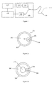
- Figures 6a and 6b show another embodiment of the present invention.
- an optical fibre 601 which may be a conventional optical fibre, has at one end, a fibre optic connector 602.
- Fibre optic connecting devices are known for focussing radiation to or from an optical fibre.
- the fibre optic connector may be connected to a splitter or circulator for passing radiation to be transmitted to the fibre and directing back-scattered radiation to the detector.
- fibre optic connector 602 comprises a lens 603 and a housing 604 which holds the lens in place relative to the end of the optical fibre 601.
- the lens is arranged to focus radiation to the centre of the optical fibre, i.e. point 605 illustrated in the cross section of Figure 6a .
- the fibre optic coupler is arranged to focus radiation into the optical fibre offset from the centre of the fibre, e.g. at position 606.
- the radiation will be coupled into the optical fibre at the edge of the core region and the maximum intensity of light with the core will be at the edge of the core.
- the bending experienced at the edge of the core will be generally greater than that at the centre of the core and hence by coupling the radiation into the fibre such that the maximum intensity is at the edges of the core, the amount of back-scatter can be maximised.
- An optical fibre 401 comprises an optical core region 402 and cladding region 403 as described above.
- the optical fibre comprises one or move stiffening members 404 which act to provide stiffness to the optical fibre in one preferential direction only.
- the stiffness members comprise flat structures that run throughout the length of the fibre and are arranged so that their thick edges are all aligned.
- the thick edge of each member is shown as being aligned horizontally.
- the stiffness member may comprise a thin strip of metal or plastic and acts to provide a resistance to flexing in one direction, in this instance the horizontal left-to-right direction, whilst allowing movement in the other direction, in this instance the vertical direction.
- a thin, strip like member of a relatively flexible material orientated as shown in figure 4 may be easily bent up and down without much resistance but may not easily flex from side to side.
- the stiffness member acts to provide the optical fibre with a preferred direction of movement.
- the fibre may be relatively easily flexed in the vertical direction but will not easily be flexed in the horizontal direction.
- the embodiments of shown in Figure 4 may therefore be used to preferentially respond to incident disturbances in the vertical direction. This may allow the components of an incident wave to be resolved in the vertical direction. For example if a pressure wave is incident on either of the fibres shown in figure 4 from the left or the right the wave may induce very little movement of the fibres and hence there would be very little change in the back-scattered radiation. A pressure wave incident from the top or bottom would cause the fibre to vibrate (as illustrated in Figure 3 ). This would result in a change to the amount of back-scattered radiation which would be detected as a disturbance of the fibre. A pressure wave incident from a direction which is 45° to the vertical would cause a certain amount of vibration in the up and down direction due to the component of the incident wave in the up and down direction.
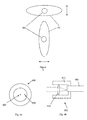
- FIG. 5 shows another embodiment of fibre optic cable.
- Figure 5 shows two fibre optic cables 501 of identical design.
- Each fibre optic cable has an optical fibre 502, which comprises an optical core and cladding and may optionally comprise at least one buffer and/or at least one jacket material as described previously.
- Surrounding the optical fibre is material of the cable.
- the cable has a cross sectional shape which is wider in one direction than the other, in this instance an elliptical shape.
- each fibre will preferentially bend in the direction of the short axis and will be resistant to bending in the direction of the long axis.
- the cable could comprise stiffening members as described above to further prevent movement in the direction of the long axis.
- the two fibres are arranged relatively close to one another and substantially parallel and are aligned so that the preferential direction of vibration of one fibre (illustrated by the arrows) is orthogonal to that of the other fibre.
- Any incident acoustic wave (which shall be taken to mean any type of incident pressure wave, including seismic waves) which has a component perpendicular to the general axis that the fibres extend along will thus be resolved into orthogonal components by the two fibres.
- Such an arrangement can be useful in seismic surveying and especially in down-well applications for instance for detecting and mapping fractures.
Landscapes
- Physics & Mathematics (AREA)
- General Physics & Mathematics (AREA)
- Optics & Photonics (AREA)
- Optical Transform (AREA)
- Measurement Of Mechanical Vibrations Or Ultrasonic Waves (AREA)
- Investigating Or Analysing Materials By Optical Means (AREA)
- Communication Cables (AREA)
- Light Guides In General And Applications Therefor (AREA)
Applications Claiming Priority (2)
| Application Number | Priority Date | Filing Date | Title |
|---|---|---|---|
| GBGB0919902.7A GB0919902D0 (en) | 2009-11-13 | 2009-11-13 | Improvements in fibre optic cables for distributed sensing |
| EP10787860.5A EP2499472B1 (de) | 2009-11-13 | 2010-11-11 | Glasfasern und faseroptischer sensor |
Related Parent Applications (2)
| Application Number | Title | Priority Date | Filing Date |
|---|---|---|---|
| EP10787860.5A Division EP2499472B1 (de) | 2009-11-13 | 2010-11-11 | Glasfasern und faseroptischer sensor |
| EP10787860.5A Division-Into EP2499472B1 (de) | 2009-11-13 | 2010-11-11 | Glasfasern und faseroptischer sensor |
Publications (3)
| Publication Number | Publication Date |
|---|---|
| EP2803957A2 true EP2803957A2 (de) | 2014-11-19 |
| EP2803957A3 EP2803957A3 (de) | 2015-01-21 |
| EP2803957B1 EP2803957B1 (de) | 2017-01-11 |
Family
ID=41509334
Family Applications (2)
| Application Number | Title | Priority Date | Filing Date |
|---|---|---|---|
| EP14179065.9A Not-in-force EP2803957B1 (de) | 2009-11-13 | 2010-11-11 | Glasfasern und faseroptische Abtastung |
| EP10787860.5A Active EP2499472B1 (de) | 2009-11-13 | 2010-11-11 | Glasfasern und faseroptischer sensor |
Family Applications After (1)
| Application Number | Title | Priority Date | Filing Date |
|---|---|---|---|
| EP10787860.5A Active EP2499472B1 (de) | 2009-11-13 | 2010-11-11 | Glasfasern und faseroptischer sensor |
Country Status (10)
| Country | Link |
|---|---|
| US (2) | US9677956B2 (de) |
| EP (2) | EP2803957B1 (de) |
| CN (2) | CN102822645B (de) |
| AU (1) | AU2010317792B2 (de) |
| BR (1) | BR112012011226B1 (de) |
| CA (3) | CA3051560A1 (de) |
| EA (2) | EA032731B1 (de) |
| GB (1) | GB0919902D0 (de) |
| MY (1) | MY162097A (de) |
| WO (1) | WO2011058314A1 (de) |
Cited By (2)
| Publication number | Priority date | Publication date | Assignee | Title |
|---|---|---|---|---|
| WO2018222541A1 (en) | 2017-05-31 | 2018-12-06 | Corning Research & Development Corporation | Optical sensing cable with acoustic lensing or reflecting features |
| GB2553709B (en) * | 2015-03-18 | 2021-02-24 | Baker Hughes A Ge Co Llc | Method of measuring acoustic energy impinging upon a cable |
Families Citing this family (62)
| Publication number | Priority date | Publication date | Assignee | Title |
|---|---|---|---|---|
| US20110290477A1 (en) | 2008-12-31 | 2011-12-01 | Jaeaeskelaeinen Kari-Mikko | Method for monitoring deformation of well equipment |
| WO2010091404A1 (en) | 2009-02-09 | 2010-08-12 | Shell Oil Company | Method of detecting fluid in-flows downhole |
| AU2009339275B2 (en) | 2009-02-09 | 2013-06-27 | Shell Internationale Research Maatschappij B.V. | Areal monitoring using distributed acoustic sensing |
| CN104314552B (zh) | 2009-05-27 | 2017-09-26 | 光学感应器控股有限公司 | 压裂监测 |
| GB0919902D0 (en) | 2009-11-13 | 2009-12-30 | Qinetiq Ltd | Improvements in fibre optic cables for distributed sensing |
| GB0919906D0 (en) * | 2009-11-13 | 2009-12-30 | Qinetiq Ltd | Improvements to distributed fibre optic sensing |
| US9109944B2 (en) | 2009-12-23 | 2015-08-18 | Shell Oil Company | Method and system for enhancing the spatial resolution of a fiber optical distributed acoustic sensing assembly |
| WO2011079107A2 (en) * | 2009-12-23 | 2011-06-30 | Shell Oil Company | Detecting broadside and directional acoustic signals with a fiber optical distributed acoustic sensing (das) assembly |
| US8605542B2 (en) | 2010-05-26 | 2013-12-10 | Schlumberger Technology Corporation | Detection of seismic signals using fiber optic distributed sensors |
| US9140815B2 (en) | 2010-06-25 | 2015-09-22 | Shell Oil Company | Signal stacking in fiber optic distributed acoustic sensing |
| EP2656112A2 (de) * | 2010-12-21 | 2013-10-30 | Shell Internationale Research Maatschappij B.V. | Detektion der richtung eines akustischen signals mithilfe einer faseroptischen anordnung zur verteilten akustikerfassung |
| CA2821583C (en) | 2010-12-21 | 2019-09-24 | Shell Internationale Research Maatschappij B.V. | System and method for making distributed measurements using fiber optic cable |
| AU2012225422B2 (en) | 2011-03-09 | 2015-07-02 | Shell Internationale Research Maatschappij B.V. | Integrated fiber optic monitoring system for a wellsite and method of using same |
| AU2012257724B2 (en) | 2011-05-18 | 2015-06-18 | Shell Internationale Research Maatschappij B.V. | Method and system for protecting a conduit in an annular space around a well casing |
| AU2012271016B2 (en) | 2011-06-13 | 2014-12-04 | Shell Internationale Research Maatschappij B.V. | Hydraulic fracture monitoring using active seismic sources with receivers in the treatment well |
| US9091589B2 (en) | 2011-06-20 | 2015-07-28 | Shell Oil Company | Fiber optic cable with increased directional sensitivity |
| GB201112161D0 (en) * | 2011-07-15 | 2011-08-31 | Qinetiq Ltd | Portal monitoring |
| CA2844334C (en) | 2011-08-09 | 2019-10-22 | Shell Internationale Research Maatschappij B.V. | Method and apparatus for measuring seismic parameters of a seismic vibrator |
| BR112014014565B1 (pt) | 2011-12-15 | 2022-06-28 | Shell Internationale Research Maatschappij B.V. | Sistema de detecção acústica de fibra óptica distribuída |
| WO2013098321A2 (en) * | 2011-12-30 | 2013-07-04 | Shell Internationale Research Maatschappij B.V. | Smart hydrocarbon fluid production method and system |
| CN104094137A (zh) | 2012-01-06 | 2014-10-08 | 普拉德研究及开发股份有限公司 | 用于地震勘测的光纤井部署 |
| GB201203273D0 (en) | 2012-02-24 | 2012-04-11 | Qinetiq Ltd | Monitoring transport network infrastructure |
| GB2519009B (en) | 2012-08-01 | 2017-09-13 | Shell Int Research | Cable comprising twisted sinusoid for use in distributed sensing |
| GB201219331D0 (en) | 2012-10-26 | 2012-12-12 | Optasense Holdings Ltd | Fibre optic cable for acoustic/seismic sensing |
| AT513732B1 (de) * | 2012-11-27 | 2015-05-15 | Fct Fiber Cable Technology Gmbh | Verfahren zur ortsaufgelösten Druckmessung |
| US10036242B2 (en) | 2013-08-20 | 2018-07-31 | Halliburton Energy Services, Inc. | Downhole acoustic density detection |
| US10087751B2 (en) | 2013-08-20 | 2018-10-02 | Halliburton Energy Services, Inc. | Subsurface fiber optic stimulation-flow meter |
| GB2518216B (en) * | 2013-09-13 | 2018-01-03 | Silixa Ltd | Non-isotropic fibre optic acoustic cable |
| EP3044554B1 (de) | 2013-09-13 | 2023-04-19 | Silixa Ltd. | Glasfaserkabel für ein verteiltes akustisches sensorsystem |
| GB2552760B (en) * | 2013-09-13 | 2018-05-16 | Silixa Ltd | Fibre optic cable having discrete acoustic coupling regions |
| GB2552761B (en) * | 2013-09-13 | 2018-05-16 | Silixa Ltd | Non-isotropic acoustic cable |
| US10295690B2 (en) | 2013-09-18 | 2019-05-21 | Halliburton Energy Services, Inc. | Distributed seismic sensing for in-well monitoring |
| US9063315B2 (en) | 2013-09-24 | 2015-06-23 | Baker Hughes Incorporated | Optical cable, downhole system having optical cable, and method thereof |
| US10843290B2 (en) | 2015-01-19 | 2020-11-24 | Weatherford Technology Holdings, Llc | Acoustically enhanced optical cables |
| WO2016144336A1 (en) | 2015-03-10 | 2016-09-15 | Halliburton Energy Services Inc. | A wellbore monitoring system using strain sensitive optical fiber cable package |
| WO2016144337A1 (en) | 2015-03-10 | 2016-09-15 | Halliburton Energy Services Inc. | A Method of Manufacturing a Distributed Acoustic Sensing Cable |
| WO2016144334A1 (en) | 2015-03-10 | 2016-09-15 | Halliburton Energy Services Inc. | A strain sensitive optical fiber cable package for downhole distributed acoustic sensing |
| NL2015406B1 (en) * | 2015-09-07 | 2017-03-22 | Fugro Tech Bv | Optical sensor device with enhanced shock absorption. |
| US11530606B2 (en) | 2016-04-07 | 2022-12-20 | Bp Exploration Operating Company Limited | Detecting downhole sand ingress locations |
| EP3670830B1 (de) | 2016-04-07 | 2021-08-11 | BP Exploration Operating Company Limited | Erkennung von bohrlochereignissen mit akustischen frequenzbereichsmerkmalen |
| US10558006B2 (en) * | 2016-06-13 | 2020-02-11 | Carlisle Interconnect Technologies, Inc. | Fiber-optic cable and method of manufacture |
| EP3583296B1 (de) | 2017-03-31 | 2021-07-21 | BP Exploration Operating Company Limited | Bohrloch- und abraumüberwachung mithilfe verteilter akustiksensoren |
| CA3064899A1 (en) * | 2017-05-31 | 2018-12-06 | Corning Research & Development Corporation | Strain sensing optical cable with acoustic impedance matched layers |
| US10263696B2 (en) * | 2017-06-12 | 2019-04-16 | Network Integrity Systems, Inc. | Monitoring a fiber optic cable for intrusion using a weighted algorithm |
| AU2018321150A1 (en) | 2017-08-23 | 2020-03-12 | Bp Exploration Operating Company Limited | Detecting downhole sand ingress locations |
| EP3695099A2 (de) | 2017-10-11 | 2020-08-19 | BP Exploration Operating Company Limited | Erkennung von ereignissen mit akustischen frequenzbereichsmerkmalen |
| EP3518010A1 (de) * | 2018-01-30 | 2019-07-31 | Koninklijke Philips N.V. | Optischer formsensor, konsole und system zur optischen formerfassung und verfahren zur optischen formerfassung |
| WO2019213080A1 (en) | 2018-05-01 | 2019-11-07 | Baker Hughes, A Ge Company, Llc | Gas sensor system |
| US11287408B2 (en) | 2018-05-01 | 2022-03-29 | Baker Hughes, A Ge Company, Llc | Gas sensor including optic fiber connector |
| US20210389486A1 (en) | 2018-11-29 | 2021-12-16 | Bp Exploration Operating Company Limited | DAS Data Processing to Identify Fluid Inflow Locations and Fluid Type |
| GB201820331D0 (en) | 2018-12-13 | 2019-01-30 | Bp Exploration Operating Co Ltd | Distributed acoustic sensing autocalibration |
| IT201900004679A1 (it) * | 2019-03-28 | 2020-09-28 | Univ Degli Studi Della Campania Luigi Vanvitelli | Trasduttore perfezionato |
| CN110045457B (zh) * | 2019-04-11 | 2020-06-26 | 电子科技大学 | 一种基于包层软化和多包层结构的声波增敏光纤 |
| EP4045766A1 (de) | 2019-10-17 | 2022-08-24 | Lytt Limited | Flüssigkeitszuflusscharakterisierung unter verwendung von hybriden das/dts-messungen |
| CA3154435C (en) | 2019-10-17 | 2023-03-28 | Lytt Limited | Inflow detection using dts features |
| WO2021093974A1 (en) | 2019-11-15 | 2021-05-20 | Lytt Limited | Systems and methods for draw down improvements across wellbores |
| KR20210080995A (ko) * | 2019-12-23 | 2021-07-01 | (주)에프비지코리아 | 광섬유격자센서를 이용한 비탈면 변위 측정장치 |
| CN111256805B (zh) * | 2020-01-06 | 2022-06-03 | 武汉理工光科股份有限公司 | 分布式光纤振动传感器振动源横向定位方法及系统 |
| US11387898B2 (en) * | 2020-02-24 | 2022-07-12 | Nec Corporation | Distributed sensing over switched optical fiber networks |
| CA3180595A1 (en) | 2020-06-11 | 2021-12-16 | Lytt Limited | Systems and methods for subterranean fluid flow characterization |
| EP4168647A1 (de) | 2020-06-18 | 2023-04-26 | Lytt Limited | Ereignismodelltraining unter verwendung von in-situ-daten |
| RU2757682C1 (ru) * | 2021-03-25 | 2021-10-20 | Федеральное государственное бюджетное образовательное учреждение высшего образования "Поволжский государственный университет телекоммуникаций и информатики" | Способ контроля состояния смотрового устройства на трассе волоконно-оптической кабельной линии |
Citations (3)
| Publication number | Priority date | Publication date | Assignee | Title |
|---|---|---|---|---|
| US5194847A (en) | 1991-07-29 | 1993-03-16 | Texas A & M University System | Apparatus and method for fiber optic intrusion sensing |
| US6380534B1 (en) | 1996-12-16 | 2002-04-30 | Sensornet Limited | Distributed strain and temperature sensing system |
| GB2442745A (en) | 2006-10-13 | 2008-04-16 | At & T Corp | Acoustic sensing using an optical fibre |
Family Cites Families (66)
| Publication number | Priority date | Publication date | Assignee | Title |
|---|---|---|---|---|
| US4110554A (en) * | 1978-02-08 | 1978-08-29 | Custom Cable Company | Buoyant tether cable |
| US4772089A (en) * | 1982-04-02 | 1988-09-20 | Polyplastics Co., Ltd. | Optical fiber cable and method for producing same |
| US4784454A (en) * | 1982-08-02 | 1988-11-15 | Andrew Corporation | Optical fiber and laser interface device |
| DE3305234C2 (de) * | 1983-02-16 | 1986-02-27 | Felten & Guilleaume Energietechnik GmbH, 5000 Köln | Zugfester Draht aus einer faserverstärkten Harzstruktur mit mindestens einem darin eingeschlossenen Lichtwellenleiter |
| US4645298A (en) * | 1983-07-28 | 1987-02-24 | At&T Bell Laboratories | Optical fiber cable |
| GB8432402D0 (en) * | 1984-12-21 | 1985-02-06 | Birch R D | Optical fibres |
| GB2197953B (en) * | 1986-11-27 | 1990-06-06 | Plessey Co Plc | Acoustic sensor |
| US4815079A (en) * | 1987-12-17 | 1989-03-21 | Polaroid Corporation | Optical fiber lasers and amplifiers |
| JP3099346B2 (ja) | 1990-06-08 | 2000-10-16 | 大日本インキ化学工業株式会社 | アニオンリビングポリマーの製造方法およびこの製造方法で得られたアニオンリビングポリマーを用いるポリマーの製造方法 |
| US5210810A (en) * | 1991-12-19 | 1993-05-11 | At&T Bell Laboratories | Hermaphroditic connector for single fiber optical cable |
| US5390273A (en) * | 1992-04-02 | 1995-02-14 | Pirelli Cable Corporation | Flame resistant optical fiber cable with optical fibers loosely enclosed in tubes |
| US5367376A (en) * | 1992-08-20 | 1994-11-22 | The United States Of America As Represented By The Secretary Of The Navy | Planar and linear fiber optic acoustic sensors embedded in an elastomer material |
| US5307436A (en) * | 1993-04-20 | 1994-04-26 | Corning Incorporated | Partially detached core optical waveguide |
| US5448670A (en) * | 1994-06-10 | 1995-09-05 | Commscope, Inc. | Elliptical aerial self-supporting fiber optic cable and associated apparatus and methods |
| WO1997008791A1 (en) * | 1995-08-31 | 1997-03-06 | Sdl, Inc. | Optical fibre for improved power coupling |
| US5768462A (en) * | 1996-03-05 | 1998-06-16 | Kvh Industries, Inc. | Grooved optical fiber for use with an electrode and a method for making same |
| GB9709627D0 (en) * | 1997-05-13 | 1997-07-02 | Hewlett Packard Co | Multimode communications systems |
| JP3511574B2 (ja) | 1997-06-18 | 2004-03-29 | 日本電信電話株式会社 | 単心光ファイバコードおよび光テープコード |
| US5905834A (en) * | 1997-07-21 | 1999-05-18 | Pirelli Cable Corporation | Combination loose tube optical fiber cable with reverse oscillating lay |
| US6085009A (en) * | 1998-05-12 | 2000-07-04 | Alcatel | Water blocking gels compatible with polyolefin optical fiber cable buffer tubes and cables made therewith |
| BR9915956B1 (pt) * | 1998-12-04 | 2011-10-18 | sensor de pressão, e, método para sensoriar pressão. | |
| US6343174B1 (en) * | 1999-07-30 | 2002-01-29 | Ceramoptec Industries, Inc. | Laser delivery system with optical fibers having fluid delivery channels |
| US6621951B1 (en) * | 2000-06-27 | 2003-09-16 | Oluma, Inc. | Thin film structures in devices with a fiber on a substrate |
| CA2412041A1 (en) | 2000-06-29 | 2002-07-25 | Paulo S. Tubel | Method and system for monitoring smart structures utilizing distributed optical sensors |
| US6742936B1 (en) * | 2000-11-06 | 2004-06-01 | Corning Cable Systems Llc | Low-loss intermatable ferrules for optical fibers and a method of fabrication thereof |
| US6876799B2 (en) * | 2001-05-09 | 2005-04-05 | Alcatel | Gel-swellable layers on fibers, fiber ribbons and buffer tubes |
| US6625363B2 (en) * | 2001-06-06 | 2003-09-23 | Nufern | Cladding-pumped optical fiber |
| US6687445B2 (en) * | 2001-06-25 | 2004-02-03 | Nufern | Double-clad optical fiber for lasers and amplifiers |
| US6749446B2 (en) * | 2001-10-10 | 2004-06-15 | Alcatel | Optical fiber cable with cushion members protecting optical fiber ribbon stack |
| DE60239424D1 (de) | 2001-12-06 | 2011-04-21 | Chiral Photonics Inc | Chirale fasersensorvorrichtung und verfahren |
| US7403687B2 (en) * | 2001-12-21 | 2008-07-22 | Pirelli Communications Cables And Systems Usa, Llc | Reinforced tight-buffered optical fiber and cables made with same |
| US6909823B1 (en) * | 2001-12-28 | 2005-06-21 | Novera Optics, Inc. | Acousto-optic tunable apparatus having a fiber bragg grating and an offset core |
| US6681071B2 (en) * | 2002-05-15 | 2004-01-20 | Fitel Usa Corp. | Dry core indoor/outdoor fiber optic cable |
| US6801687B2 (en) * | 2002-08-22 | 2004-10-05 | Terabeam Corporation | Apparatus and method for generating a mode-scrambled optical signal using a VCSEL array |
| US20040109646A1 (en) * | 2002-12-09 | 2004-06-10 | Anderson Timothy W. | Array connector/ferrule for large core ribbon fiber |
| CN1164886C (zh) * | 2002-12-10 | 2004-09-01 | 西安交通大学 | 基于分布式光纤传感器的油气管线泄漏智能在线监测方法 |
| CN1219226C (zh) * | 2002-12-27 | 2005-09-14 | 燕山大学 | 双包层塑料放大器光纤及其制造方法 |
| FR2849929B1 (fr) * | 2003-01-09 | 2005-04-15 | Sagem | Cable a fibres optiques avec gaine de maintien |
| US6937325B2 (en) * | 2003-01-30 | 2005-08-30 | Fitel U.S.A. Corporation | Method and apparatus for measuring eccentricity in a optical fiber |
| WO2005010562A2 (en) * | 2003-07-18 | 2005-02-03 | Network Integrity Systems, Inc. | Multimode fiber optic intrusion detection system |
| US7403675B2 (en) * | 2003-07-18 | 2008-07-22 | Network Integrity Systems Inc. | Method of high order mode excitation for multimode intrusion detection |
| US7376293B2 (en) * | 2003-07-18 | 2008-05-20 | Network Intergrity Systems Inc. | Remote location of active section of fiber in a multimode intrusion detection system |
| US7403674B2 (en) * | 2003-07-18 | 2008-07-22 | Network Integrity Systems Inc. | Intrusion detection system for a multimode optical fiber using a bulk optical wavelength division multiplexer for maintaining modal power distribution |
| JP3860201B2 (ja) * | 2003-08-13 | 2006-12-20 | 日本電信電話株式会社 | 光ファイバの製造方法 |
| US7101623B2 (en) * | 2004-03-19 | 2006-09-05 | Dow Global Technologies Inc. | Extensible and elastic conjugate fibers and webs having a nontacky feel |
| US7304724B2 (en) * | 2004-04-13 | 2007-12-04 | The Regents Of The University Of California | Method and apparatus for quantification of optical properties of superficial volumes |
| US20060024001A1 (en) * | 2004-07-28 | 2006-02-02 | Kyocera Corporation | Optical fiber connected body with mutually coaxial and inclined cores, optical connector for forming the same, and mode conditioner and optical transmitter using the same |
| FI20045308A (fi) * | 2004-08-26 | 2006-02-27 | Corelase Oy | Optinen kuituvahvistin, jossa on vahvistuksen muotoerottelu |
| PL1812816T3 (pl) * | 2004-11-05 | 2017-09-29 | Prysmian S.P.A. | Sposób kontrolowania rozprzestrzeniania się wody w kablu optycznym |
| GB0500277D0 (en) * | 2005-01-07 | 2005-02-16 | Southampton Photonics Ltd | Apparatus for propagating optical radiation |
| US7333681B2 (en) * | 2005-08-03 | 2008-02-19 | Network Integrity Systems, Inc. | Intrusion detection and location system for use on multimode fiber optic cable |
| RU2319988C2 (ru) * | 2005-10-31 | 2008-03-20 | Общество с ограниченной ответственностью "Инверсия-Сенсор" | Оптоволоконная мультисенсорная система, датчик температуры/деформации для оптоволоконной мультисенсорной системы, способ записи датчика (варианты) |
| JP4768405B2 (ja) * | 2005-11-09 | 2011-09-07 | 東日本旅客鉄道株式会社 | 光ファイバセンサー及び歪・温度観測システム |
| GB0524838D0 (en) * | 2005-12-06 | 2006-01-11 | Sensornet Ltd | Sensing system using optical fiber suited to high temperatures |
| US7590321B2 (en) * | 2006-03-09 | 2009-09-15 | Adc Telecommunications, Inc. | Mid-span breakout with helical fiber routing |
| WO2007104915A1 (en) * | 2006-03-14 | 2007-09-20 | Schlumberger Holdings Limited | System and method for monitoring structures |
| US20080124032A1 (en) * | 2006-04-28 | 2008-05-29 | Christopher Horvath | System and Method of Protecting Optical Cables |
| US20080217303A1 (en) * | 2006-07-06 | 2008-09-11 | Lockheed Martin Corporation | Optical fiber fusion splice device for use in confined spaces |
| US7609925B2 (en) * | 2007-04-12 | 2009-10-27 | Adc Telecommunications, Inc. | Fiber optic cable breakout configuration with tensile reinforcement |
| JP2009063356A (ja) * | 2007-09-05 | 2009-03-26 | Fujikura Ltd | 光ファイバセンサケーブル |
| JP2009156718A (ja) * | 2007-12-27 | 2009-07-16 | Yokogawa Electric Corp | 光パルス試験装置 |
| FR2926640B1 (fr) | 2008-01-18 | 2010-08-20 | Draka Comteq France Sa | Fibre optique gainee et cable de telecommunication |
| US8326103B2 (en) * | 2008-04-04 | 2012-12-04 | Baker Hughes Incorporated | Cable and method |
| US8957312B2 (en) * | 2009-07-16 | 2015-02-17 | 3M Innovative Properties Company | Submersible composite cable and methods |
| GB0919902D0 (en) | 2009-11-13 | 2009-12-30 | Qinetiq Ltd | Improvements in fibre optic cables for distributed sensing |
| US8374473B2 (en) * | 2010-05-05 | 2013-02-12 | Ofs Fitel, Llc | Tight-buffered optical fiber having improved fiber access |
-
2009
- 2009-11-13 GB GBGB0919902.7A patent/GB0919902D0/en not_active Ceased
-
2010
- 2010-11-11 US US13/509,425 patent/US9677956B2/en active Active
- 2010-11-11 WO PCT/GB2010/002074 patent/WO2011058314A1/en active Application Filing
- 2010-11-11 AU AU2010317792A patent/AU2010317792B2/en not_active Ceased
- 2010-11-11 CN CN201080061395.6A patent/CN102822645B/zh not_active Expired - Fee Related
- 2010-11-11 CA CA3051560A patent/CA3051560A1/en not_active Abandoned
- 2010-11-11 EP EP14179065.9A patent/EP2803957B1/de not_active Not-in-force
- 2010-11-11 CA CA3051561A patent/CA3051561A1/en not_active Abandoned
- 2010-11-11 EP EP10787860.5A patent/EP2499472B1/de active Active
- 2010-11-11 EA EA201400829A patent/EA032731B1/ru not_active IP Right Cessation
- 2010-11-11 EA EA201290303A patent/EA029335B1/ru not_active IP Right Cessation
- 2010-11-11 CN CN201810447612.3A patent/CN108645430A/zh active Pending
- 2010-11-11 CA CA2780569A patent/CA2780569C/en active Active
- 2010-11-11 BR BR112012011226A patent/BR112012011226B1/pt not_active IP Right Cessation
- 2010-11-11 MY MYPI2012002086A patent/MY162097A/en unknown
-
2017
- 2017-06-12 US US15/620,196 patent/US11099085B2/en active Active
Patent Citations (3)
| Publication number | Priority date | Publication date | Assignee | Title |
|---|---|---|---|---|
| US5194847A (en) | 1991-07-29 | 1993-03-16 | Texas A & M University System | Apparatus and method for fiber optic intrusion sensing |
| US6380534B1 (en) | 1996-12-16 | 2002-04-30 | Sensornet Limited | Distributed strain and temperature sensing system |
| GB2442745A (en) | 2006-10-13 | 2008-04-16 | At & T Corp | Acoustic sensing using an optical fibre |
Cited By (3)
| Publication number | Priority date | Publication date | Assignee | Title |
|---|---|---|---|---|
| GB2553709B (en) * | 2015-03-18 | 2021-02-24 | Baker Hughes A Ge Co Llc | Method of measuring acoustic energy impinging upon a cable |
| WO2018222541A1 (en) | 2017-05-31 | 2018-12-06 | Corning Research & Development Corporation | Optical sensing cable with acoustic lensing or reflecting features |
| EP3631521A4 (de) * | 2017-05-31 | 2021-02-17 | Corning Research & Development Corporation | Optisches sensorkabel mit akustischen linsen- oder reflektierenden merkmalen |
Also Published As
| Publication number | Publication date |
|---|---|
| EA201290303A1 (ru) | 2012-12-28 |
| EP2803957A3 (de) | 2015-01-21 |
| US20170343433A1 (en) | 2017-11-30 |
| EA032731B1 (ru) | 2019-07-31 |
| AU2010317792B2 (en) | 2014-07-24 |
| CN102822645A (zh) | 2012-12-12 |
| GB0919902D0 (en) | 2009-12-30 |
| CA2780569C (en) | 2019-09-24 |
| EA201400829A1 (ru) | 2015-03-31 |
| US11099085B2 (en) | 2021-08-24 |
| MY162097A (en) | 2017-05-31 |
| US9677956B2 (en) | 2017-06-13 |
| CA3051561A1 (en) | 2011-05-19 |
| CN108645430A (zh) | 2018-10-12 |
| EP2803957B1 (de) | 2017-01-11 |
| EA029335B1 (ru) | 2018-03-30 |
| BR112012011226B1 (pt) | 2020-01-21 |
| CN102822645B (zh) | 2018-07-27 |
| AU2010317792A1 (en) | 2012-07-05 |
| BR112012011226A2 (pt) | 2018-03-27 |
| CA2780569A1 (en) | 2011-05-19 |
| EP2499472A1 (de) | 2012-09-19 |
| US20120222487A1 (en) | 2012-09-06 |
| WO2011058314A1 (en) | 2011-05-19 |
| EP2499472B1 (de) | 2016-01-27 |
| CA3051560A1 (en) | 2011-05-19 |
Similar Documents
| Publication | Publication Date | Title |
|---|---|---|
| US11099085B2 (en) | Optic fibres and fibre optic sensing | |
| US9243949B2 (en) | Fibre optic distributed sensing | |
| EP3204747B1 (de) | Lichtwellenleiterkabel mit abgestimmter transversaler empfindlichkeit | |
| US10345139B2 (en) | Non-isotropic acoustic cable | |
| US9816853B2 (en) | Fibre optic cable for acoustic/seismic sensing | |
| WO2018142113A1 (en) | Cable for distributed sensing | |
| WO2012028845A1 (en) | Improvements in fibre optic cables for distributed sensing | |
| AU2014253508B2 (en) | Optic fibres and fibre optic sensing | |
| EP3850311B1 (de) | Faseroptische kabel | |
| GB2518216A (en) | Non-isotropic acoustic cable | |
| GB2552761A (en) | Non-isotropic acoustic cable design | |
| GB2552760A (en) | Non-isotropic accoustic cable design |
Legal Events
| Date | Code | Title | Description |
|---|---|---|---|
| PUAI | Public reference made under article 153(3) epc to a published international application that has entered the european phase |
Free format text: ORIGINAL CODE: 0009012 |
|
| 17P | Request for examination filed |
Effective date: 20140730 |
|
| AC | Divisional application: reference to earlier application |
Ref document number: 2499472 Country of ref document: EP Kind code of ref document: P |
|
| AK | Designated contracting states |
Kind code of ref document: A2 Designated state(s): AL AT BE BG CH CY CZ DE DK EE ES FI FR GB GR HR HU IE IS IT LI LT LU LV MC MK MT NL NO PL PT RO RS SE SI SK SM TR |
|
| PUAL | Search report despatched |
Free format text: ORIGINAL CODE: 0009013 |
|
| AK | Designated contracting states |
Kind code of ref document: A3 Designated state(s): AL AT BE BG CH CY CZ DE DK EE ES FI FR GB GR HR HU IE IS IT LI LT LU LV MC MK MT NL NO PL PT RO RS SE SI SK SM TR |
|
| RIC1 | Information provided on ipc code assigned before grant |
Ipc: G01H 9/00 20060101AFI20141212BHEP Ipc: G02B 6/032 20060101ALI20141212BHEP Ipc: G02B 6/02 20060101ALI20141212BHEP Ipc: G01L 11/02 20060101ALI20141212BHEP Ipc: G02B 6/44 20060101ALI20141212BHEP Ipc: G01L 1/24 20060101ALI20141212BHEP Ipc: G01D 5/353 20060101ALI20141212BHEP Ipc: G02B 6/036 20060101ALI20141212BHEP |
|
| R17P | Request for examination filed (corrected) |
Effective date: 20150721 |
|
| RBV | Designated contracting states (corrected) |
Designated state(s): AL AT BE BG CH CY CZ DE DK EE ES FI FR GB GR HR HU IE IS IT LI LT LU LV MC MK MT NL NO PL PT RO RS SE SI SK SM TR |
|
| GRAP | Despatch of communication of intention to grant a patent |
Free format text: ORIGINAL CODE: EPIDOSNIGR1 |
|
| INTG | Intention to grant announced |
Effective date: 20160621 |
|
| GRAS | Grant fee paid |
Free format text: ORIGINAL CODE: EPIDOSNIGR3 |
|
| GRAA | (expected) grant |
Free format text: ORIGINAL CODE: 0009210 |
|
| STAA | Information on the status of an ep patent application or granted ep patent |
Free format text: STATUS: THE PATENT HAS BEEN GRANTED |
|
| AC | Divisional application: reference to earlier application |
Ref document number: 2499472 Country of ref document: EP Kind code of ref document: P |
|
| AK | Designated contracting states |
Kind code of ref document: B1 Designated state(s): AL AT BE BG CH CY CZ DE DK EE ES FI FR GB GR HR HU IE IS IT LI LT LU LV MC MK MT NL NO PL PT RO RS SE SI SK SM TR |
|
| REG | Reference to a national code |
Ref country code: GB Ref legal event code: FG4D |
|
| REG | Reference to a national code |
Ref country code: CH Ref legal event code: EP |
|
| REG | Reference to a national code |
Ref country code: AT Ref legal event code: REF Ref document number: 861736 Country of ref document: AT Kind code of ref document: T Effective date: 20170115 |
|
| REG | Reference to a national code |
Ref country code: IE Ref legal event code: FG4D |
|
| REG | Reference to a national code |
Ref country code: DE Ref legal event code: R096 Ref document number: 602010039627 Country of ref document: DE |
|
| REG | Reference to a national code |
Ref country code: NL Ref legal event code: FP |
|
| REG | Reference to a national code |
Ref country code: LT Ref legal event code: MG4D |
|
| REG | Reference to a national code |
Ref country code: AT Ref legal event code: MK05 Ref document number: 861736 Country of ref document: AT Kind code of ref document: T Effective date: 20170111 |
|
| PG25 | Lapsed in a contracting state [announced via postgrant information from national office to epo] |
Ref country code: NO Free format text: LAPSE BECAUSE OF FAILURE TO SUBMIT A TRANSLATION OF THE DESCRIPTION OR TO PAY THE FEE WITHIN THE PRESCRIBED TIME-LIMIT Effective date: 20170411 Ref country code: IS Free format text: LAPSE BECAUSE OF FAILURE TO SUBMIT A TRANSLATION OF THE DESCRIPTION OR TO PAY THE FEE WITHIN THE PRESCRIBED TIME-LIMIT Effective date: 20170511 Ref country code: FI Free format text: LAPSE BECAUSE OF FAILURE TO SUBMIT A TRANSLATION OF THE DESCRIPTION OR TO PAY THE FEE WITHIN THE PRESCRIBED TIME-LIMIT Effective date: 20170111 Ref country code: HR Free format text: LAPSE BECAUSE OF FAILURE TO SUBMIT A TRANSLATION OF THE DESCRIPTION OR TO PAY THE FEE WITHIN THE PRESCRIBED TIME-LIMIT Effective date: 20170111 Ref country code: GR Free format text: LAPSE BECAUSE OF FAILURE TO SUBMIT A TRANSLATION OF THE DESCRIPTION OR TO PAY THE FEE WITHIN THE PRESCRIBED TIME-LIMIT Effective date: 20170412 Ref country code: LT Free format text: LAPSE BECAUSE OF FAILURE TO SUBMIT A TRANSLATION OF THE DESCRIPTION OR TO PAY THE FEE WITHIN THE PRESCRIBED TIME-LIMIT Effective date: 20170111 |
|
| PG25 | Lapsed in a contracting state [announced via postgrant information from national office to epo] |
Ref country code: PT Free format text: LAPSE BECAUSE OF FAILURE TO SUBMIT A TRANSLATION OF THE DESCRIPTION OR TO PAY THE FEE WITHIN THE PRESCRIBED TIME-LIMIT Effective date: 20170511 Ref country code: RS Free format text: LAPSE BECAUSE OF FAILURE TO SUBMIT A TRANSLATION OF THE DESCRIPTION OR TO PAY THE FEE WITHIN THE PRESCRIBED TIME-LIMIT Effective date: 20170111 Ref country code: LV Free format text: LAPSE BECAUSE OF FAILURE TO SUBMIT A TRANSLATION OF THE DESCRIPTION OR TO PAY THE FEE WITHIN THE PRESCRIBED TIME-LIMIT Effective date: 20170111 Ref country code: BG Free format text: LAPSE BECAUSE OF FAILURE TO SUBMIT A TRANSLATION OF THE DESCRIPTION OR TO PAY THE FEE WITHIN THE PRESCRIBED TIME-LIMIT Effective date: 20170411 Ref country code: ES Free format text: LAPSE BECAUSE OF FAILURE TO SUBMIT A TRANSLATION OF THE DESCRIPTION OR TO PAY THE FEE WITHIN THE PRESCRIBED TIME-LIMIT Effective date: 20170111 Ref country code: AT Free format text: LAPSE BECAUSE OF FAILURE TO SUBMIT A TRANSLATION OF THE DESCRIPTION OR TO PAY THE FEE WITHIN THE PRESCRIBED TIME-LIMIT Effective date: 20170111 Ref country code: SE Free format text: LAPSE BECAUSE OF FAILURE TO SUBMIT A TRANSLATION OF THE DESCRIPTION OR TO PAY THE FEE WITHIN THE PRESCRIBED TIME-LIMIT Effective date: 20170111 Ref country code: PL Free format text: LAPSE BECAUSE OF FAILURE TO SUBMIT A TRANSLATION OF THE DESCRIPTION OR TO PAY THE FEE WITHIN THE PRESCRIBED TIME-LIMIT Effective date: 20170111 |
|
| REG | Reference to a national code |
Ref country code: DE Ref legal event code: R097 Ref document number: 602010039627 Country of ref document: DE |
|
| PG25 | Lapsed in a contracting state [announced via postgrant information from national office to epo] |
Ref country code: IT Free format text: LAPSE BECAUSE OF FAILURE TO SUBMIT A TRANSLATION OF THE DESCRIPTION OR TO PAY THE FEE WITHIN THE PRESCRIBED TIME-LIMIT Effective date: 20170111 Ref country code: RO Free format text: LAPSE BECAUSE OF FAILURE TO SUBMIT A TRANSLATION OF THE DESCRIPTION OR TO PAY THE FEE WITHIN THE PRESCRIBED TIME-LIMIT Effective date: 20170111 Ref country code: EE Free format text: LAPSE BECAUSE OF FAILURE TO SUBMIT A TRANSLATION OF THE DESCRIPTION OR TO PAY THE FEE WITHIN THE PRESCRIBED TIME-LIMIT Effective date: 20170111 Ref country code: CZ Free format text: LAPSE BECAUSE OF FAILURE TO SUBMIT A TRANSLATION OF THE DESCRIPTION OR TO PAY THE FEE WITHIN THE PRESCRIBED TIME-LIMIT Effective date: 20170111 Ref country code: SK Free format text: LAPSE BECAUSE OF FAILURE TO SUBMIT A TRANSLATION OF THE DESCRIPTION OR TO PAY THE FEE WITHIN THE PRESCRIBED TIME-LIMIT Effective date: 20170111 |
|
| PLBE | No opposition filed within time limit |
Free format text: ORIGINAL CODE: 0009261 |
|
| STAA | Information on the status of an ep patent application or granted ep patent |
Free format text: STATUS: NO OPPOSITION FILED WITHIN TIME LIMIT |
|
| PG25 | Lapsed in a contracting state [announced via postgrant information from national office to epo] |
Ref country code: DK Free format text: LAPSE BECAUSE OF FAILURE TO SUBMIT A TRANSLATION OF THE DESCRIPTION OR TO PAY THE FEE WITHIN THE PRESCRIBED TIME-LIMIT Effective date: 20170111 Ref country code: SM Free format text: LAPSE BECAUSE OF FAILURE TO SUBMIT A TRANSLATION OF THE DESCRIPTION OR TO PAY THE FEE WITHIN THE PRESCRIBED TIME-LIMIT Effective date: 20170111 |
|
| 26N | No opposition filed |
Effective date: 20171012 |
|
| PG25 | Lapsed in a contracting state [announced via postgrant information from national office to epo] |
Ref country code: SI Free format text: LAPSE BECAUSE OF FAILURE TO SUBMIT A TRANSLATION OF THE DESCRIPTION OR TO PAY THE FEE WITHIN THE PRESCRIBED TIME-LIMIT Effective date: 20170111 |
|
| PG25 | Lapsed in a contracting state [announced via postgrant information from national office to epo] |
Ref country code: MC Free format text: LAPSE BECAUSE OF FAILURE TO SUBMIT A TRANSLATION OF THE DESCRIPTION OR TO PAY THE FEE WITHIN THE PRESCRIBED TIME-LIMIT Effective date: 20170111 |
|
| PG25 | Lapsed in a contracting state [announced via postgrant information from national office to epo] |
Ref country code: LI Free format text: LAPSE BECAUSE OF NON-PAYMENT OF DUE FEES Effective date: 20171130 Ref country code: CH Free format text: LAPSE BECAUSE OF NON-PAYMENT OF DUE FEES Effective date: 20171130 |
|
| PG25 | Lapsed in a contracting state [announced via postgrant information from national office to epo] |
Ref country code: LU Free format text: LAPSE BECAUSE OF NON-PAYMENT OF DUE FEES Effective date: 20171111 |
|
| REG | Reference to a national code |
Ref country code: FR Ref legal event code: ST Effective date: 20180731 Ref country code: BE Ref legal event code: MM Effective date: 20171130 |
|
| REG | Reference to a national code |
Ref country code: IE Ref legal event code: MM4A |
|
| PG25 | Lapsed in a contracting state [announced via postgrant information from national office to epo] |
Ref country code: MT Free format text: LAPSE BECAUSE OF NON-PAYMENT OF DUE FEES Effective date: 20171111 |
|
| PG25 | Lapsed in a contracting state [announced via postgrant information from national office to epo] |
Ref country code: FR Free format text: LAPSE BECAUSE OF NON-PAYMENT OF DUE FEES Effective date: 20171130 Ref country code: IE Free format text: LAPSE BECAUSE OF NON-PAYMENT OF DUE FEES Effective date: 20171111 |
|
| PG25 | Lapsed in a contracting state [announced via postgrant information from national office to epo] |
Ref country code: BE Free format text: LAPSE BECAUSE OF NON-PAYMENT OF DUE FEES Effective date: 20171130 |
|
| PG25 | Lapsed in a contracting state [announced via postgrant information from national office to epo] |
Ref country code: HU Free format text: LAPSE BECAUSE OF FAILURE TO SUBMIT A TRANSLATION OF THE DESCRIPTION OR TO PAY THE FEE WITHIN THE PRESCRIBED TIME-LIMIT; INVALID AB INITIO Effective date: 20101111 |
|
| PG25 | Lapsed in a contracting state [announced via postgrant information from national office to epo] |
Ref country code: CY Free format text: LAPSE BECAUSE OF FAILURE TO SUBMIT A TRANSLATION OF THE DESCRIPTION OR TO PAY THE FEE WITHIN THE PRESCRIBED TIME-LIMIT Effective date: 20170111 |
|
| PG25 | Lapsed in a contracting state [announced via postgrant information from national office to epo] |
Ref country code: MK Free format text: LAPSE BECAUSE OF FAILURE TO SUBMIT A TRANSLATION OF THE DESCRIPTION OR TO PAY THE FEE WITHIN THE PRESCRIBED TIME-LIMIT Effective date: 20170111 |
|
| PGFP | Annual fee paid to national office [announced via postgrant information from national office to epo] |
Ref country code: DE Payment date: 20191125 Year of fee payment: 10 Ref country code: NL Payment date: 20191125 Year of fee payment: 10 |
|
| PG25 | Lapsed in a contracting state [announced via postgrant information from national office to epo] |
Ref country code: TR Free format text: LAPSE BECAUSE OF FAILURE TO SUBMIT A TRANSLATION OF THE DESCRIPTION OR TO PAY THE FEE WITHIN THE PRESCRIBED TIME-LIMIT Effective date: 20170111 |
|
| PGFP | Annual fee paid to national office [announced via postgrant information from national office to epo] |
Ref country code: GB Payment date: 20191125 Year of fee payment: 10 |
|
| PG25 | Lapsed in a contracting state [announced via postgrant information from national office to epo] |
Ref country code: AL Free format text: LAPSE BECAUSE OF FAILURE TO SUBMIT A TRANSLATION OF THE DESCRIPTION OR TO PAY THE FEE WITHIN THE PRESCRIBED TIME-LIMIT Effective date: 20170111 |
|
| REG | Reference to a national code |
Ref country code: DE Ref legal event code: R082 Ref document number: 602010039627 Country of ref document: DE Representative=s name: HL KEMPNER PATENTANWALT, RECHTSANWALT, SOLICIT, DE |
|
| REG | Reference to a national code |
Ref country code: DE Ref legal event code: R119 Ref document number: 602010039627 Country of ref document: DE |
|
| REG | Reference to a national code |
Ref country code: NL Ref legal event code: MM Effective date: 20201201 |
|
| GBPC | Gb: european patent ceased through non-payment of renewal fee |
Effective date: 20201111 |
|
| PG25 | Lapsed in a contracting state [announced via postgrant information from national office to epo] |
Ref country code: NL Free format text: LAPSE BECAUSE OF NON-PAYMENT OF DUE FEES Effective date: 20201201 |
|
| PG25 | Lapsed in a contracting state [announced via postgrant information from national office to epo] |
Ref country code: GB Free format text: LAPSE BECAUSE OF NON-PAYMENT OF DUE FEES Effective date: 20201111 Ref country code: DE Free format text: LAPSE BECAUSE OF NON-PAYMENT OF DUE FEES Effective date: 20210601 |
|
| P01 | Opt-out of the competence of the unified patent court (upc) registered |
Effective date: 20230524 |