EP2803942B1 - Vorrichtung und Verfahren zur Überprüfung der Geradheit von gezogenen Stäben - Google Patents
Vorrichtung und Verfahren zur Überprüfung der Geradheit von gezogenen Stäben Download PDFInfo
- Publication number
- EP2803942B1 EP2803942B1 EP14168474.6A EP14168474A EP2803942B1 EP 2803942 B1 EP2803942 B1 EP 2803942B1 EP 14168474 A EP14168474 A EP 14168474A EP 2803942 B1 EP2803942 B1 EP 2803942B1
- Authority
- EP
- European Patent Office
- Prior art keywords
- supporting
- checking apparatus
- frame
- drawn
- bars
- Prior art date
- Legal status (The legal status is an assumption and is not a legal conclusion. Google has not performed a legal analysis and makes no representation as to the accuracy of the status listed.)
- Active
Links
Images


Classifications
-
- G—PHYSICS
- G01—MEASURING; TESTING
- G01B—MEASURING LENGTH, THICKNESS OR SIMILAR LINEAR DIMENSIONS; MEASURING ANGLES; MEASURING AREAS; MEASURING IRREGULARITIES OF SURFACES OR CONTOURS
- G01B11/00—Measuring arrangements characterised by the use of optical techniques
- G01B11/24—Measuring arrangements characterised by the use of optical techniques for measuring contours or curvatures
- G01B11/245—Measuring arrangements characterised by the use of optical techniques for measuring contours or curvatures using a plurality of fixed, simultaneously operating transducers
Definitions
- the present invention generally relates to the field of bar or rod drawing and in particular to an apparatus and a method for verifying the straightness of drawn bars along a manufacturing line.
- Drawing is a process based on cold plastic deformation of metallic materials, wherein the cross section of a workpiece is reduced.
- Cold drawing is widely used in the production of profiled bars, tubes, rods and metal wires, because it allows to obtain a very good surface finish and a high dimensional accuracy.
- a workpiece is suitably pulled and made to pass through a calibrated hole, whose cavity has a frustum-conical shape converging in the drawing or pulling direction.
- a calibrated hole whose cavity has a frustum-conical shape converging in the drawing or pulling direction.
- the cross-section of the article is therefore smaller than the cross-section it has at the inlet.
- Straightness errors may for example be caused by uneven wear of calibrated holes, which determines a uneven discharge of the drawn material in the circumferential direction. Moreover, an incorrect positioning of calibrated holes with respect to the pulling direction of the drawn product may cause straightness problems.
- US3376968 discloses an apparatus adapted to move elongated articles from one station to another past a location at which a work is performed on the articles, in which the articles are held at each end by grippers mounted on an endless chain.
- US4201476 teaches to use a laser gauge to measure a dimension of a workpiece, wherein a laser beam is directed through a beam splitter to a rotating mirror at the focal point of a parabolic mirror. This rotating mirror causes the laser beam to scan the parabolic mirror and establish a series of parallel laser beams emanating from the parabolic mirror and directed toward the workpiece which may be a hot forged bar.
- US4927029 discloses a device for checking tubes transported along a feed path from a tube container to a distribution mechanism by means of a chain conveyor with feed blades and with a cyclical intermittent motion. The arrangement includes a centering device mounted transversely with respect to the feed path of the tubes at the location where the blades of the chain conveyor are cyclically stopped.
- US3024905 discloses an automatic apparatus for inspecting elongated open ended tubular glass envelopes for detecting defects, such as waves in the annular end surface.
- US1309086 discloses an assorting machine including an article carrier, means for moving the carrier, and means to gage the size of a carried article.
- US4197888 discloses log centering apparatus and method for determining the optimum yield axis of logs, and a method employing a light transmission type optical scanner with a reference edge means spaced from the side of the log and located in the light path to the light detector so that the scanner measures the log axis in a more accurate and stable manner and is not sensitive to movement of the light detector.
- Drawn bars must therefore be subject to strict quality controls, e.g. using optical instruments that detect the position of a plurality of portions of a bar at predetermined distances, for example at the ends and at a central location, and calculate straightness errors by way of a suitable algorithm.
- Straightness checks are generally carried out on samples comprising a limited number of drawn bars that are laid on a supporting plane above which a plurality of video cameras are mounted. On the supporting surface a bar may freely assume its own possible curved configuration, thus allowing to verify whether it meets the straightness tolerances required for a specific use.
- An idea of solution underlying the present invention is to make a checking apparatus comprising a measuring group associated with a supporting and moving group configured to store a plurality of bars received directly from a drawing apparatus and to bring them one after the other to a measuring station. This configuration allows to arrange the checking apparatus in series with a drawing apparatus without penalizing its hourly throughput.
- the supporting and moving group is so configured to move the bars in a vertical direction, thus allowing to minimize the overall size of the checking apparatus.
- Drawn bars are received on respective vertically movable supporting planes at a picking station of the supporting and moving group, the picking station being aligned with an outlet of a drawing apparatus.
- the drawn bars are then moved in the vertical direction towards a measuring station proximate to which the measuring group is arranged.
- the supporting planes support the bars at a plurality of discrete portions that are spaced apart from each other and not along their whole surface. This minimizes the contact surface allowing a bar to quickly take the natural curvature resulting from the drawing process. In fact the retention effect due to friction forces arising from the contact with the supporting surface are much smaller than those resulting from the contact with a continuous surface.
- the supporting planes comprise a plurality of mutually spaced sectors.
- the supporting planes are divided into sectors, but also the whole supporting and moving group, whose frame comprises a plurality of units arranged in parallel.
- This modular configuration of the supporting and moving group is extremely advantageous, because it allows to simplify the overall structure of the control apparatus.
- Each unit includes a set of sectors of the supporting planes and driving means suitable to allow their movement.
- the units are driven such that the sets of sectors that form the different supporting planes are moved simultaneously thus remaining aligned.
- operation of the units of the supporting and moving group is controlled by way of a single motor connected thereto through a motor shaft and the movement of the sectors of the supporting planes is obtained by way of respective mechanical transmissions every one of which comprises a sprocket keyed to the motor shaft, wherein the sprocket directly engages the sectors of the supporting planes.
- the sectors of the supporting planes are slidably restrained to the respective units along inner guides and they may advantageously be arranged along these guides in contact among each other.
- the sectors moved by the sprocket mutually push each other, thus completely eliminating positioning problems related to mechanical plays and allowing to achieve a very high precision of alignment among the sectors of a same supporting plane, as well as coordination between the checking apparatus and the drawing apparatus from which this receives the drawn bars.
- the distance among the units of the frame of the supporting and moving group is advantageously adjustable, so that the checking apparatus may receive and measure drawn bars having different lengths.
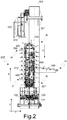
- control apparatus is generally designated by the reference numeral 100 and includes a supporting and moving group 200 adapted to receive a plurality of bars from a drawing apparatus, as well as measuring group 300 suitable for measuring the straightness of said bars.
- control apparatus 100 is a part of a drawing plant for bars (not shown) and is arranged at an outlet (not shown) from which finished bars are discharged. This configuration allows loading of the drawn bars produced from the drawing apparatus directly in the checking apparatus 100, which may thus carry out straightness checks on every one of them.
- the drawn bars which are schematically indicated by reference number 400 and e.g. have a circular cross section, come out from the drawing apparatus along a horizontal direction H that is substantially parallel to the supporting surface of the checking apparatus 100, and proceed in this direction toward the control apparatus 100 as schematically indicated by arrow F.
- the supporting and moving group 200 comprises a plurality of supporting planes 210 respectively configured to receive a drawn bar 400 at a picking station P and to transport it to a measuring station M proximate to which the measuring group 300 is arranged.
- the supporting planes 210 are movable in a generally vertical direction V, perpendicular to the supporting surface of the checking apparatus 100.
- the supporting planes 210 are movably restrained to a frame 220 that extends vertically and comprises a base 221 and a top 222.
- the configuration of the supporting and moving group 200 is such that the supporting planes 210 move cyclically around the frame 220 rising from the base 221 toward the top 222 along a front side of the frame 220.
- the supporting planes 210 are rotated by 180° and then descend towards the base 221 along a rear side of the frame 220, opposite to the front side with respect to a transverse direction T perpendicular to the horizontal and vertical directions H, V.
- the supporting planes 210 are rotated again by 180° thus reaching the front side of the frame 220.
- each supporting plane 210 receives a drawn bar 400 at the picking station P of the frame 220, which is arranged proximate to its base 221, and moves it along the lifting direction L toward the top 222 of the frame 220 proximate to which the measuring station M is arranged.
- the measuring group 300 is arranged proximate to the measuring station M and comprises a plurality of video cameras 310 arranged above the supporting and moving group 200 in the vertical direction V.
- the video cameras 310 are also arranged parallel and spaced apart from each other in the horizontal direction H, and are respectively configured to focus a plurality of discrete portions of a drawn bar 400.
- the video cameras are suitable to focus the end portions and the middle portion of a drawn bar 400.
- the video cameras 310 are equipped with a telecentric lens assembly and are mounted on a frame 320 of the measuring group 300 comprising a pair of vertical uprights 321 and a cross member 322 extending in the horizontal direction H.
- the video cameras 310 are mounted on the cross member 322 by way of suitable frames 323.
- the vertical uprights 321 are arranged at the ends of the supporting and moving group 200 and the cross member 322 with the video cameras 310 is arranged over the top 222 of the frame 220 in the vertical direction V, so that the overall configuration of the whole control apparatus 100 is generally vertical.
- the position of the portions of a bar 400 focused by each of the video cameras 310 is compared to a reference straight direction corresponding to the direction along which the cross member 322 extends.
- Straightness errors of the bar 400 are calculated on the basis of one or more reference points within each of the portions focused by the video cameras 310.
- the picking station P includes a concave surface on which the drawn bars 400 coming out from the drawing apparatus are received. Due to their own weights the drawn bars 400 move in the lowest point of the concave surface, which is suitably aligned with the axes of the lenses of the video cameras 310.
- the drawn bars 400 are retained at the measuring station M for a predetermined time, for example in the order of about 1 second, so that the movement of the supporting planes 210 is an intermittent movement comprising advancing phases alternating to stop phases.
- the measuring time and the times that characterize the phases of advancement and stop of the supporting planes 210 are also synchronized with the production rate of the drawing apparatus. In fact every bar 400 produced by the drawing apparatus is directly loaded in the supporting and moving group 200 on one of its supporting planes 210 and brought to the measuring group 300.
- the supporting planes 210 go beyond the top 222 of the frame 220 and return to the base 221. Therefore, in correspondence with the top 222 the supporting planes 210 are rotated by 180° relative to the supporting surface of the control apparatus 100 and the drawn bars 400 in contact with one surface of the respective supporting plane 210 during the lifting step from the picking station P to the measuring station M, come into contact with the surface of the supporting plane 210 that precedes it in the lifting direction L.
- the outlet station O comprises a chute that allows to discharge the drawn bars 400 measured by the checking apparatus 100.
- the supporting planes 210 are moved past the outlet station O toward the base 221 of the frame 220, in correspondence of which are rotated again by 180° relative to the ground and return to the picking station P where they receive a new drawn bar 400 to be measured.
- the supporting planes 210 are not continuous surfaces, but are formed of a plurality of sectors 210', 210", 210"', etc., which are mutually parallel and spaced apart in the horizontal direction H.
- each of the sectors 210', 210", 210''', etc. supports a portion of a drawn bar 400.
- the bars 400 are not supported on continuous surfaces, but on discrete surfaces at a plurality of portions that are mutually spaced apart. This minimizes the contact surface and allows a drawn bar 400 to assume the, possible, curvature resulting from the drawing process more easily and quickly, because of the reduced retaining effect caused by frictional forces caused by the contact with the respective supporting plane.
- the supporting planes 210 include seven parallel sectors 210', 210", 210"', etc.. Experimental tests have allowed to verify that this number is a good compromise between the supporting surface required for the handling of the drawn bars 400 and the friction forces acting thereon.
- movement of the supporting planes 210 is intermittent in order to allow to carry out straightness measurements at the measuring station M.
- the alternation of advancing phases and stop phases causes accelerations and decelerations of the supporting planes 210 in the vertical direction V and consequently also of the bars 400. This facilitates the arrangement of the drawn bars according to the possible curvature resulting from the drawing process.
- This feature of the invention is synergistic with the configuration of the supporting planes 210 in the form of parallel sectors 210', 210", 210"', etc., because it allows to intermittently neutralize friction forces acting on the portions of the drawn bars 400 contacting the sectors 210', 210", 210''', etc., of the respective supporting planes 210, thus further facilitating arrangement of a drawn bar 400 according to possible curved configuration deriving from its drawing process.
- control apparatus 100 is provided with a backlighting system associated with the supporting and moving group 200.
- the backlighting system comprises a plurality of lamps 500 movable relative to the frame 220 of the supporting and moving group 200 between an internal position, wherein they do not interfere with the passage of the supporting planes 210 and an outer position, wherein they are arranged between two subsequent supporting planes 210, in particular below the supporting plane 210 arranged at the measuring station M, hence under a drawn bar 400 to be measured.
- the lamps 500 are respectively aligned with the video cameras 310 of the measuring group in the horizontal and vertical directions H, V and, during the stop phase for carrying out the measurements, they cast a beam of light in the vertical direction V towards the portions of a bar 400 arranged above, and then toward a video camera 310 arranged thereat.
- the light beam increases visibility of the portions of the bar 400 and creates a contrast effect which facilitates identification of the reference points for measurement.
- the lamps 500 and the video cameras 310 are arranged aside the parallel sectors 210', 210", 210"', etc., of the supporting planes 210 in the horizontal direction H.
- This arrangement allows not to create interference problems between the light rays emitted by the lamps 500 and the sectors 210', 210", 210''', etc., of the supporting planes 210.
- This arrangement also allows to maximize the contrast effect of the light against the drawn bars 400, thus effectively contributing to the accuracy in determining the straightness errors.
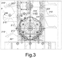
- the frame 220 of the whole supporting and moving group 200 which, as shown in figure 1 , comprises a plurality of units 220', 220", 220''', etc., operating in parallel, every one of which comprises a respective set of sectors 210', 210", 210''', etc., of the supporting planes 210.
- the units of the frame 220 are in particular seven, which, as explained above, corresponds to the preferred number of sectors of the supporting planes 210.
- the apparatus 100 in order to control in a synchronized manner the movement of the sectors 210', 210", 210'', etc., of the different sets so as to correctly define the flat surfaces of the support planes 210, the apparatus 100 includes a single drive shaft 600 to which driving means for the operation of respective sets of parallel sectors are connected.
- driving means will be described in detail hereinafter.
- the motor shaft 600 crosses the parallel units 220', 220", 220''', etc., of the frame 220 and is connected at one end to a motor 700, e.g. an electric motor, through a coupling 710.
- the motor 700 and the coupling 710 are arranged at one end of the supporting and moving group 200 in the horizontal direction H.
- the drive shaft 600 is rotatably restrained to a support 610 provided with a suitable bearing.
- each unit 220', 220", 220''', etc., of the frame 220 houses a set of respective sectors 210', 210", 210''', etc., of the supporting planes 210, which circulate around the respective unit of the frame 220 running from its base to its top along the front side and then down towards the base along the rear side and back again on the front side.
- each set of sectors 210', 210", 210''', etc., of the supporting planes 210 is operated by way of transmission means that are completely mechanical.
- transmission means that are completely mechanical.
- the sectors 210' are housed in the unit 220' and slidably arranged along guides 223' formed along its inner periphery and configured to allow their displacement from the base 221' towards the top 222' along the front side of the unit 220' where the picking and measuring stations P, M are arranged and then along the rear side of the unit 220' from the top 222' to the base 221' where the outlet station O is arranged.
- the sectors 210' may advantageously be provided with bearings 211' mounted on the portion intended to engage the guides 223'.
- the sectors 210' are arranged in the guides 223' in contact with one another, i.e. without mechanical plays, which allows to maintain the supporting and moving group 200 perfectly synchronized with the drawing apparatus from which it receives the drawn bars 400 for straightness measurements.
- a toothed wheel 224' keyed to the motor shaft 600 is arranged at the base 221' of the container of the unit 220'.
- the teeth of the wheel are configured to simultaneously engage the ends of two subsequent sectors 210'.
- the teeth of the toothed wheel 224' e.g. engage the roll bearings 211' of the two subsequent sectors 210'.
- the toothed wheel 224' driven by the motor shaft 600 moves the sectors 210' thus making them move along the guides 223' between the base 221' and the top 222' of the unit 220'.
- the thrusts that the sectors 210' exert against one another in the descending direction D from the top 222' to the base 221' of the unit 220' generates a torque on the toothed wheel 224' which results in a force in the lifting direction L allowing to minimize the torque required by the motor 700 to move the sectors 210' from the base 221' to the top 222'.
- This configuration also allows to minimize torsion effects of the motor shaft 600 between the different units 220', 220", 220''', etc., which are spaced apart in the horizontal direction H.
- the backlighting system is not associated with all the units 220', 220", 220'', etc., of the frame 220 of the supporting and moving group 200, but only with the units arranged at the video cameras 310 of the measuring group 300, e.g. the three units of the illustrated embodiment.
- a first toothed pulley 225 is keyed to the motor shaft 600 coaxially to the toothed wheel 224'.
- a chain 226' is connected to the toothed pulley to drive a second toothed pulley 227' arranged proximate to the top 222' of the unit 220'.
- the second pulley 227' drives the movement of the displacement means associated with the lamps 500 of the backlighting system.
- these displacement means e.g.
- the slider 503' is configured for mounting at least one lamp 500 of the backlighting system.
- the transmission ratio between the first and the second pulley 225', 227' is defined so as to allow movement of the slider 503' from the outside to the inside of the unit 220' in a first half of the time required by an advancement phase, so as to allow advancement of another drawn bar 400 to be measured toward the measuring station M.
- the movement of the unit 220' from the inside to the outside occurs in a second half of the time required by the advancing step, so as to bring the lamp 500 between two subsequent sectors 210' under the drawn bar 400 to be measured.
- the movement of the lamps 500 of the backlighting system might be alternatively obtained with different displacement means, for example by way of linear actuators controlled by a suitable control system.
- the configuration described above is advantageous because it has an extremely simple structure from a mechanical point of view and allows to keep the movements of the lamps 500 perfectly synchronized with the movements of the sectors of the supporting planes 210.
- control apparatus 100 may be configured so as to allow measurement of the straightness of drawn bars 400 having different lengths, for example comprised between 3 and 5 meters.
- the units 220', 220", 220'', etc., of the frame 220 of the supporting and moving group 200 and the video cameras 310 of the measuring group 300 are movably mounted in the horizontal direction H.
- the units 220', 220", 220''', etc., of the frame 220 and the video cameras 310 of the measuring group 300 are respectively connected to each other by way of linear actuators configured so as to allow relative movements that are progressively greater the greater is their distance from a fixed point of the control apparatus 100.
- the apparatus 100 comprises a base 110 on which the units 220', 220", 220'', etc., of the frame 220 of the supporting and moving group 200 are movably arranged along the horizontal direction H.
- the base 110 comprises a pair of rails 120 on which the units 220', 220", 220''', etc., are placed in correspondence of their respective bases 221', 221", 221'', etc..
- One of the units for example the unit 220' arranged at the end of the supporting and moving group 200 proximate to which the motor 700 is arranged, is fixed, whereas the other units are movable along the rails 120.
- the video cameras 310 of the measuring group 300 are movably mounted in the horizontal direction H, so as to allow to maintain the checking points corresponding to the end portions and the central portion of a drawn bar 400.
- the cross member 322 of the frame 320 is provided with a rail 324 along which the video cameras 310 are slidably mounted.
- one of the video cameras e.g. the video camera 310' aligned with the unit 220' arranged at the end of the supporting and moving group 200 proximate to which the motor 700 is arranged, is fixed, whereas the other video cameras 310", 310''' are movable along the rail 324.
- the movements of the movable units 220", 220''', etc., and video cameras 310", 310''' which allow to adapt the control apparatus 100 to bars having different lengths may advantageously be coordinated so as to maintain corresponding mutual distances, i.e. the distances between the individual units 220', 220", 220''', etc., of the frame 220 and the distances between the individual video cameras 310 of the measuring group 300.
- the movable units 220", 220''', etc. may be restrained to each other by way of linear actuators configured so as to allow displacements progressively greater the greater is their distance from the fixed unit 220'.
- linear actuators may for example comprise worm screws, connected to one another and to a same motor 800 by way of respective couplings (not shown).
- the movable video cameras 310", 310''' are connected to one another by way of linear actuators (not shown) configured to allow displacements that are progressively greater the greater is their distance from the fixed video camera 310'.
- the linear actuators may e.g. comprise worm screws connected together and to a same motor 900 by way of respective couplings (not shown).
- Driving of the sectors 210', 210", 210'', etc., of the supporting planes 210 might e.g. be achieved by way of individual motors mounted on the units 220', 220", 220''', etc., the motors being synchronized by way of a feedback control system.
- the measuring group 300 might comprise multiple video cameras, for example three groups of three video cameras respectively arranged at the end portions and the central portion of a drawn bar 400.
Landscapes
- Physics & Mathematics (AREA)
- General Physics & Mathematics (AREA)
- Length Measuring Devices By Optical Means (AREA)
- Coating With Molten Metal (AREA)
- Manufacture, Treatment Of Glass Fibers (AREA)
- Metal Extraction Processes (AREA)
Claims (15)
- Eine Prüfvorrichtung (100) zum Überprüfen der Geradheit von gezogenen Stäben, wobei die besagte Prüfvorrichtung (100) eine Stütz- und Bewegungs-Baugruppe (200) umfasst, welche dazu ausgelegt ist, eine Mehrzahl von gezogenen Stäben (400) von einer Ziehvorrichtung entlang einer horizontalen Richtung (H) aufzunehmen, sowie eine Mess-Baugruppe (300), welche dazu geeignet ist, die Geradheit der besagten gezogenen Stäbe (400) zu messen, wobei die besagte Stütz- und Bewegungs-Baugruppe (200) eine Mehrzahl von Auflageebenen (210) umfasst, von denen jede dazu ausgelegt ist, einen gezogenen Stab (400) an der Aufnahmestation (P) der Stütz- und Bewegungs-Baugruppe (200) aufzunehmen und ihn zu einer Messstation (M) der Stütz- und Bewegungs-Baugruppe (200), in deren Nähe sich die Mess-Baugruppe (300) befindet, zu bewegen, wobei die besagten Auflageebenen (210) in einer vertikalen Richtung (V) rechtwinklig zu der besagten horizontalen Richtung (H) beweglich sind, und wobei die Auflageebenen (210) aus einer Mehrzahl von Abschnitten (210', 210", 210''') gebildet sind, welche parallel zueinander sind und in der horizontalen Richtung (H) voneinander entfernt sind und eine Stützfläche der Prüfvorrichtung (100) zum Abstützen der gezogenen Stäbe (400) in Kontakt mit der besagten Stützfläche definieren, wobei die Mess-Baugruppe (300) eine Mehrzahl von Videokameras (310) umfasst, welche in der vertikalen Richtung (V) oberhalb der Stütz- und Bewegungs-Baugruppe (200) angeordnet sind, und wobei die Prüfvorrichtung (100) ferner ein Hintergrund-Beleuchtungssystem umfasst, wobei das besagte Hintergrund-Beleuchtungssystem ein Verschiebemittel umfasst, welches dazu ausgelegt ist, eine Mehrzahl von relativ zu einem Rahmen (220) der Stütz- und Bewegungs-Baugruppe (200) beweglicher Lampen (500) zwischen einer inneren Position, in welcher sie den Durchgang der Auflageebenen (210) nicht behindern, und einer äußeren Position, in welcher sie unterhalb derjenigen Auflageebene (210) ist, die sich an der Messstation (M) befindet, zu bewegen, wobei die besagte Stütz- und Bewegungs-Baugruppe (200) ein Antriebsmittel umfasst, welches dazu ausgelegt ist, um die besagten Auflageebenen (210) in der vertikalen Richtung (V) rechtwinklig zu der horizontalen Richtung (H) zu bewegen, wobei die besagte horizontale Richtung (H) parallel zu der stützenden Oberfläche ist, so wie die besagten Auflageebenen (210) in der vertikalen Richtung (V) beweglich sind, um den besagten gezogenen Stab (400) in Kontakt mit der besagten stützenden Oberfläche in einer Hubrichtung (L) parallel zu der besagten vertikalen Richtung (V) anzuheben, und wobei die stützende Oberfläche der Prüfvorrichtung (100) rechtwinklig zu der besagten vertikalen Richtung (V) ist;
wobei der Rahmen (220) der Stütz- und Bewegungs-Baugruppe (200) sich in der vertikalen Richtung (V) erstreckt und einen Basisbereich (221) umfasst sowie einen oberen Bereich (222), wobei die Anordnung der Stütz- und Bewegungs-Baugruppe (200) derart ist, dass die Auflageebenen (210) um den besagten Rahmen herum zirkulieren, indem sie sich entlang einer Vorderseite des Rahmens (220) von dem Basisbereich (221) in Richtung zu dem oberen Bereich (222) bewegen, sich in Übereinstimmung mit dem oberen Bereich (222) um 180° drehen und entlang einer der besagten Vorderseite im Hinblick auf eine Transversalrichtung (T) rechtwinklig zu der horizontalen (H) und der vertikalen (V) Richtung gegenüberliegenden Rückseite des Rahmens (220) zu dem Basisbereich (221) niederfahren entlang einer von dem oberen Bereich (222) zu dem Basisbereich (221) absteigenden Richtung (D), parallel und entgegengesetzt zu der vertikalen Richtung (V) und unterschieden von der Hubrichtung (L), und wobei die Auflageebenen (210) in Übereinstimmung mit dem Basisbereich (221) wieder um 180° rotieren und zu der Vorderseite des Rahmens (220) zurückkehren. - Eine Prüfvorrichtung (100) gemäß Anspruch 1, wobei die besagten Auflageebenen (210) aus sieben Abschnitten gebildet sind.
- Eine Prüfvorrichtung (100) gemäß Anspruch 1, wobei die besagte Aufnahmestation (P) und die Messstation (M) an der Vorderseite des Rahmens (220) der Stütz- und Bewegungs-Baugruppe (200) angeordnet sind, und wobei eine Auslassstation (O) an der Rückseite des Rahmens (220) angeordnet ist, wobei die besagte Auslassstation (O) derart gestaltet ist, dass sie eine Ausgabe der gezogenen Stäbe (400) erlaubt, nachdem diese durch die Mess-Baugruppe (300) vermessen wurden.
- Eine Prüfvorrichtung (100) gemäß einem der Ansprüche 1 bis 3, wobei die Videokameras (310) der Mess-Baugruppe (300) parallel zueinander und in der horizontalen Richtung (H) beabstandet angeordnet sind und derart konfiguriert sind, dass sie jeweils einen spezifischen Bereich eines gezogenen Stabs fokussieren.
- Eine Prüfvorrichtung (100) gemäß Anspruch 4, wobei die Videokameras (310) an einem Rahmen (320) der Mess-Baugruppe (300) montiert sind, wobei der besagte Rahmen (320) ein Paar von vertikalen Stützen (321) aufweist sowie einen Querträger (322), der sich in der horizontalen Richtung (H) erstreckt, wobei die Videokameras (310) an dem besagten Querträger (322) montiert sind.
- Eine Prüfvorrichtung (100) gemäß Anspruch 4 oder 5, wobei die Lampen (500) des Hintergrund-Beleuchtungssystems und die Videokameras (310) der Mess-Baugruppe (300) in der horizontalen Richtung (H) seitlich neben den Abschnitten (210', 210", 210''') der Auflageebenen (210) angeordnet sind und gemeinsam in der horizontalen (H) und vertikalen (V) Richtung ausgerichtet sind.
- Eine Prüfvorrichtung (100) gemäß einem der Ansprüche 1 bis 6, wobei der Rahmen (220) der Stütz- und Bewegungs-Baugruppe (200) eine Mehrzahl von parallelen Einheiten (220', 220", 220''') umfasst, wobei jede der besagten parallelen Einheiten (220', 220", 220''') jeweils einen Satz von Abschnitte (210', 210", 210''') der Auflageebenen (210) enthält.
- Eine Prüfvorrichtung (100) gemäß Anspruch 7, wobei die Stütz- und Bewegungs-Baugruppe (200) einen Motor (700) aufweist sowie eine mit Hilfe einer Kupplung (710) an den Motor angeschlossene Antriebswelle, wobei die besagte Antriebswelle (600) an die parallelen Einheiten (220', 220", 220''') des Rahmens (220) funktionswirksam angeschlossen ist zum Antrieb der entsprechenden Sätze von Abschnitten (210', 210", 210''') der Auflageebenen (210).
- Eine Prüfvorrichtung (100) gemäß Anspruch 8, wobei die Sätze von Abschnitten (210', 210", 210''') der Auflageebenen (210) in den entsprechenden Einheiten (220', 220", 220''') des Rahmens (220) verschiebbar entlang von Führungen (223', 223", 223''') untergebracht sind, welche entlang des inneren Randbereichs ausgebildet sind, und wobei die Abschnitte (210', 210", 210''') in den Führungen (223', 223", 223''') derart angeordnet sind, dass sie sich gegenseitig berühren und auf jenen mit Hilfe eines Zahnrads (224', 224", 224''') bewegt werden, das auf der Antriebswelle (600) aufgekeilt ist, wobei die Zähne des Zahnrads (224', 224", 224''') derart ausgelegt sind, dass sie gleichzeitig mit den Enden von zwei aufeinanderfolgenden Abschnitten (210', 210", 210''') in Eingriff stehen, so dass die Abschnitte (210', 210", 210''') sich gegenseitig anschieben, wenn sie bewegt werden.
- Eine Prüfvorrichtung (100) gemäß Anspruch 9, wobei die Einheiten (220', 220", 220''') des Rahmens (220), welchen die Lampen (500) des Hintergrund-Beleuchtungssystems zugeordnet sind, eine erste Rolle (225', 225", 225''') umfassen, die koaxial zu dem Zahnrad (224', 224", 224''') auf der Antriebswelle (600) aufgekeilt ist, sowie einen Zahnriemen (226', 226", 226'''), der funktionell an einer zweiten verzahnten Rolle (227', 227", 227''') angeschlossen ist, die in der Nähe des oberen Bereichs (222', 222", 222''') der Einheit (220', 220", 220''') des Rahmens (220) angeordnet ist, wobei die besagte zweite verzahnte Rolle (227', 227", 227''') an dem besagten Verschiebemittel funktionswirksam angeschlossen ist, das den Lampen (500) des Hintergrund-Beleuchtungssystems zugeordnet ist, wobei das besagte Verschiebemittel dazu ausgelegt ist, eine Bewegung der Lampen (500) von außerhalb der Einheiten (220', 220", 220''') nach innen zu erlauben, wenn die Abschnitte (210', 210", 210''') der Auflageebenen (210) bewegt werden, und von innerhalb der Einheiten (220', 220", 220''') nach außen, wenn die Abschnitte (210', 210", 210''') der Auflageebenen (210) stillgesetzt werden.
- Eine Prüfvorrichtung (100) gemäß Anspruch 10, wobei das besagte Verschiebemittel eine Kurbelwelle (501', 501", 501''') umfasst, die an der zweiten Rolle (227', 227", 227''') angeschlossen ist, sowie eine Verbindungsstange (502', 502", 502'''), die mit einem Ende an der Kurbelwelle (501', 501", 501''') und mit dem entgegengesetzten Ende an einem entlang der Führung (504', 504", 504''') beweglichen Schieber (503', 503", 503''') angeschlossen ist, wobei der besagte Schieber (503', 503", 503''') dazu ausgelegt ist, den Einbau mindestens einer Lampe (500) des Hintergrund-Beleuchtungssystems zu ermöglichen.
- Eine Prüfvorrichtung (100) gemäß einem der Ansprüche 7 bis 11, wobei die Einheiten (220', 220", 220''') des Rahmens (220) der Stütz- und Bewegungs-Baugruppe (200) und die Videokameras (310) der Mess-Baugruppe (300) entlang der horizontalen Richtung (H) beweglich montiert sind, wobei die Prüfvorrichtung (100) gezogene Stäbe (400) unterschiedlicher Längen aufnehmen kann.
- Eine Prüfvorrichtung (100) gemäß Anspruch 12, wobei die Einheiten (220', 220", 220''') des Rahmens (220) der Stütz- und Bewegungs-Baugruppe (200) und die Videokameras (310) der Mess-Baugruppe (300) jeweils entsprechend aneinander gehalten werden durch Linearaktuatoren, welche derart ausgelegt sind, um relative Verschiebungen zwischen ihnen zu erlauben, wobei die besagten Verschiebungen zunehmend größer sind, je größer deren Abstand von einem fixen Punkt der Prüfvorrichtung (100) ist.
- Eine Ziehvorrichtung für Stäbe, wobei die besagte Ziehvorrichtung eine Prüfvorrichtung (100) gemäß einem der Ansprüche 1 bis 13 umfasst, wobei die besagte Prüfvorrichtung (100) an dem Auslass für gezogene Stäbe (400) angeordnet ist.
- Ein Verfahren zur Überprüfung der Geradheit von gezogenen Stäben, wobei das Verfahren die folgenden Schritte aufweist:Aufnehmen gezogener Stäbe (400) von einer Ziehvorrichtung an einer Aufnahmestation (P) der Prüfvorrichtung (100), wobei die besagten gezogenen Stäbe (400) in einer horizontalen Richtung (H) der besagten Prüfvorrichtung (100) zugeführt werden;Bewegen jedes der gezogenen Stäbe (400) in Richtung zu einer Messstation (M) der besagten Prüfvorrichtung (100);Aufbewahren jedes gezogenen Stabs (400) in der besagten Messstation (M) für eine vorgegebene Messzeit;Durchführen einer Messung der Geradheit jedes gezogenen Stabs (400) in der besagten Messstation (M) während der besagten vorgegebenen Messzeit, undAusgeben der gezogenen Stäbe (400) an einer Auslassstation (O) der Prüfvorrichtung (100),wobei die gezogenen Stäbe (400) von der Aufnahmestation (P) zu der Messstation (M) bewegt werden in sich abwechselnden Schritten von Fortschreiten und Stoppen entlang einer vertikalen Richtung (V) der Prüfvorrichtung (100), rechtwinklig zu der besagten horizontalen Richtung (H), wobei in der Prüfvorrichtung die gezogenen Stäbe (400) an zugeordnete diskreten Bereichen unterstützt werden, und wobei jeder gezogene Stab (400) während des besagten Messschrittes mit Hilfe einer Mehrzahl von Videokameras (310) gemessen wird, welche jeweils bei einer Mehrzahl von diskreten Bereichen angeordnet sind, und wobei die besagten, diskreten Bereiche von Lampen (500) beleuchtet werden, welche derart angeordnet sind, um entsprechende Lichtstrahlen in Richtung zu den besagten diskreten Bereichen der gezogenen Stäbe (400) und der Videokameras (310) auszusenden,wobei die besagten gezogenen Stäbe (400) in Richtung zu der Messstation (M) in der vertikalen Richtung (V) rechtwinklig zu der horizontalen Richtung (H) bewegt werden, während sie von den Auflageebenen (210) gestützt werden, welche eine Auflageoberfläche für die gezogenen Stäbe (400) der Prüfvorrichtung (100) bilden, wobei die besagte horizontale Richtung (H) parallel zu der Auflageoberfläche ist, wobei die besagten Auflageebenen (210) in der vertikalen Richtung (V) bewegt werden, um die gezogenen Stäbe (400) in Kontakt mit den Auflageebenen (210) in einer Hubrichtung (L) parallel zu der vertikalen Richtung (V) anzuheben, wobei die Auflageoberfläche der Prüfvorrichtung (100) senkrecht zu der vertikalen Richtung (V) ist;wobei der Rahmen (220) der Stütz- und Bewegungs-Baugruppe (200) sich in der vertikalen Richtung (V) erstreckt und einen Basisbereich (221) umfasst sowie einen oberen Bereich (222), wobei die Anordnung der Stütz- und Bewegungs-Baugruppe (200) derart ist, dass die Auflageebenen (210) um den besagten Rahmen herum zirkulieren, indem sie sich entlang einer Vorderseite des Rahmens (220) von dem Basisbereich (221) in Richtung zu dem oberen Bereich (222) bewegen, sich in Übereinstimmung mit dem oberen Bereich (222) um 180° drehen und entlang einer der besagten Vorderseite im Hinblick auf eine Transversalrichtung (T) rechtwinklig zu der horizontalen (H) und der vertikalen (V) Richtung gegenüberliegenden Rückseite des Rahmens (220) zu dem Basisbereich (221) niederfahren entlang einer von dem oberen Bereich (222) zu dem Basisbereich (221) absteigenden Richtung (D), parallel und entgegengesetzt zu der vertikalen Richtung (V) und unterschieden von der Hubrichtung (L), wobei die Auflageebenen (210) in Übereinstimmung mit dem Basisbereich (221) wieder um 180° rotieren und zu der Vorderseite des Rahmens (220) zurückkehren.
Priority Applications (1)
| Application Number | Priority Date | Filing Date | Title |
|---|---|---|---|
| PL14168474T PL2803942T3 (pl) | 2013-05-16 | 2014-05-15 | Urządzenie kontrolne i sposób weryfikacji prostoliniowości prętów ciągnionych |
Applications Claiming Priority (1)
| Application Number | Priority Date | Filing Date | Title |
|---|---|---|---|
| IT000803A ITMI20130803A1 (it) | 2013-05-16 | 2013-05-16 | Apparato e metodo per il controllo della rettilineità di barre trafilate |
Publications (2)
| Publication Number | Publication Date |
|---|---|
| EP2803942A1 EP2803942A1 (de) | 2014-11-19 |
| EP2803942B1 true EP2803942B1 (de) | 2021-08-04 |
Family
ID=48951495
Family Applications (1)
| Application Number | Title | Priority Date | Filing Date |
|---|---|---|---|
| EP14168474.6A Active EP2803942B1 (de) | 2013-05-16 | 2014-05-15 | Vorrichtung und Verfahren zur Überprüfung der Geradheit von gezogenen Stäben |
Country Status (5)
| Country | Link |
|---|---|
| EP (1) | EP2803942B1 (de) |
| ES (1) | ES2893313T3 (de) |
| IT (1) | ITMI20130803A1 (de) |
| PL (1) | PL2803942T3 (de) |
| PT (1) | PT2803942T (de) |
Families Citing this family (10)
| Publication number | Priority date | Publication date | Assignee | Title |
|---|---|---|---|---|
| ITBS20150085A1 (it) * | 2015-05-15 | 2016-11-15 | Q Tech S R L | Metodo e dispositivo di misura dell'errore di rettilineita' di barre e tubi |
| DE102016103483A1 (de) * | 2016-02-26 | 2017-08-31 | Sms Group Gmbh | Geradheitmessvorrichtung und -verfahren |
| ITUA20162235A1 (it) | 2016-04-01 | 2017-10-01 | Rde Company S R L | Sistema di sostegno flottante 3D per apparecchiatura di rilevamento geometrico di corpi snelli |
| DE102016003772B4 (de) | 2016-04-02 | 2020-02-27 | Msg Maschinenbau Gmbh | Vorrichtung und Verfahren zum Messen der Geradheit eines stabförmigen Werkstücks |
| DE102018203976A1 (de) * | 2018-03-15 | 2019-09-19 | Homag Gmbh | Verfahren zur Fehlererkennung und Anlage zum Bearbeiten eines Werkstücks |
| CN114111662B (zh) * | 2021-11-11 | 2024-07-30 | 佛山市顺德区东亚汽车部件有限公司 | 一种用于汽车风扇罩的检具 |
| KR102508162B1 (ko) * | 2022-04-05 | 2023-03-09 | 김상현 | 선재 직진도 검사장치 |
| CN115156081B (zh) * | 2022-07-28 | 2023-12-01 | 中国科学院空天信息创新研究院 | 棒材分拣装置 |
| CN115350937B (zh) * | 2022-09-08 | 2023-08-04 | 欧拜欧(昆山)汽车紧固件有限公司 | 一种螺接件用自动导向和检测机构 |
| CN120084249B (zh) * | 2025-03-24 | 2025-09-23 | 江苏中金天威精密钢管有限公司 | 一种精密钢管检测装置 |
Citations (3)
| Publication number | Priority date | Publication date | Assignee | Title |
|---|---|---|---|---|
| US1309086A (en) * | 1919-07-08 | Asbignob ex thb xjbbs | ||
| US4197888A (en) * | 1978-02-21 | 1980-04-15 | The Coe Manufacturing Company | Log centering apparatus and method using transmitted light and reference edge log scanner |
| US4949769A (en) * | 1989-09-15 | 1990-08-21 | Cameron Robert E | Log delivery mechanism |
Family Cites Families (4)
| Publication number | Priority date | Publication date | Assignee | Title |
|---|---|---|---|---|
| US3024905A (en) * | 1959-05-25 | 1962-03-13 | Gen Electric | Tube end inspection apparatus |
| US3376968A (en) * | 1965-03-26 | 1968-04-09 | George T. Lott | Loading fixture |
| US4201476A (en) * | 1978-01-05 | 1980-05-06 | The Austin Company | Laser dimension gauge |
| CS261799B1 (en) * | 1987-08-31 | 1989-02-10 | Jiri Ing Trhlik | Device for cylindrical bodies checking,especially tubes with spindleless spinning frame |
-
2013
- 2013-05-16 IT IT000803A patent/ITMI20130803A1/it unknown
-
2014
- 2014-05-15 ES ES14168474T patent/ES2893313T3/es active Active
- 2014-05-15 EP EP14168474.6A patent/EP2803942B1/de active Active
- 2014-05-15 PL PL14168474T patent/PL2803942T3/pl unknown
- 2014-05-15 PT PT141684746T patent/PT2803942T/pt unknown
Patent Citations (3)
| Publication number | Priority date | Publication date | Assignee | Title |
|---|---|---|---|---|
| US1309086A (en) * | 1919-07-08 | Asbignob ex thb xjbbs | ||
| US4197888A (en) * | 1978-02-21 | 1980-04-15 | The Coe Manufacturing Company | Log centering apparatus and method using transmitted light and reference edge log scanner |
| US4949769A (en) * | 1989-09-15 | 1990-08-21 | Cameron Robert E | Log delivery mechanism |
Also Published As
| Publication number | Publication date |
|---|---|
| PL2803942T3 (pl) | 2022-01-03 |
| EP2803942A1 (de) | 2014-11-19 |
| ES2893313T3 (es) | 2022-02-08 |
| ITMI20130803A1 (it) | 2014-11-17 |
| PT2803942T (pt) | 2021-10-19 |
Similar Documents
| Publication | Publication Date | Title |
|---|---|---|
| EP2803942B1 (de) | Vorrichtung und Verfahren zur Überprüfung der Geradheit von gezogenen Stäben | |
| FI76724C (fi) | Svarv omfattande ett avstrykningsdon. | |
| CN209117604U (zh) | 一种活塞销检测机 | |
| US4230219A (en) | Cavity identification handling system | |
| FI117856B (fi) | Laite tukin keskittämiseksi ja syöttämiseksi | |
| FI75112C (fi) | Foerfarande att bedoema och laengdsaetta virke och anordning vid justerverk foer utfoerande av foerfarandet. | |
| CN110170453B (zh) | 一种管材自动化分拣系统 | |
| CN107764188A (zh) | 一种单晶硅棒长度和斜度检测装置及其检测方法 | |
| CN107414986A (zh) | 自动进料快速对心的连续破竹设备及其破竹方法 | |
| CN108680113B (zh) | 全自动玻璃检测、理片生产系统及其工作方法 | |
| CN108326074A (zh) | 加油铁管成型装置及其成型工艺 | |
| CN113532359A (zh) | 一种轴类零件外径检测装置 | |
| US5361027A (en) | Apparatus for non-contact dynamic inspections of a plurality of pieces | |
| CN106672540B (zh) | 涡流自动上下料检测设备 | |
| KR102315009B1 (ko) | 유리 커팅 장치 | |
| US7040207B2 (en) | Log merchandiser | |
| CN117532139B (zh) | 一种管材参数识别设备及方法 | |
| CN119771789A (zh) | 一种基于机器视觉的工件瑕疵检测装置 | |
| WO2016039980A1 (en) | Thru-feed measuring device for cylindrical workpieces with driven top guide | |
| EP0092418B1 (de) | Gerät und Verfahren zum Sortieren von Kraftübertragungs riemen | |
| FI101902B (fi) | Painotuotteiden paksuudenmittaus suomumaisessa kuljetusvirrassa | |
| CN111151469A (zh) | 螺栓螺纹在线检测设备 | |
| CN217505444U (zh) | 试件自动测量系统 | |
| CN116908209A (zh) | 一种用于硅片分选的检测装置 | |
| JP4643088B2 (ja) | 物品処理機械の位置調整装置とその位置調整方法 |
Legal Events
| Date | Code | Title | Description |
|---|---|---|---|
| PUAI | Public reference made under article 153(3) epc to a published international application that has entered the european phase |
Free format text: ORIGINAL CODE: 0009012 |
|
| 17P | Request for examination filed |
Effective date: 20140515 |
|
| AK | Designated contracting states |
Kind code of ref document: A1 Designated state(s): AL AT BE BG CH CY CZ DE DK EE ES FI FR GB GR HR HU IE IS IT LI LT LU LV MC MK MT NL NO PL PT RO RS SE SI SK SM TR |
|
| AX | Request for extension of the european patent |
Extension state: BA ME |
|
| R17P | Request for examination filed (corrected) |
Effective date: 20150320 |
|
| RBV | Designated contracting states (corrected) |
Designated state(s): AL AT BE BG CH CY CZ DE DK EE ES FI FR GB GR HR HU IE IS IT LI LT LU LV MC MK MT NL NO PL PT RO RS SE SI SK SM TR |
|
| STAA | Information on the status of an ep patent application or granted ep patent |
Free format text: STATUS: EXAMINATION IS IN PROGRESS |
|
| 17Q | First examination report despatched |
Effective date: 20170811 |
|
| GRAP | Despatch of communication of intention to grant a patent |
Free format text: ORIGINAL CODE: EPIDOSNIGR1 |
|
| STAA | Information on the status of an ep patent application or granted ep patent |
Free format text: STATUS: GRANT OF PATENT IS INTENDED |
|
| INTG | Intention to grant announced |
Effective date: 20201207 |
|
| GRAJ | Information related to disapproval of communication of intention to grant by the applicant or resumption of examination proceedings by the epo deleted |
Free format text: ORIGINAL CODE: EPIDOSDIGR1 |
|
| STAA | Information on the status of an ep patent application or granted ep patent |
Free format text: STATUS: EXAMINATION IS IN PROGRESS |
|
| GRAP | Despatch of communication of intention to grant a patent |
Free format text: ORIGINAL CODE: EPIDOSNIGR1 |
|
| STAA | Information on the status of an ep patent application or granted ep patent |
Free format text: STATUS: GRANT OF PATENT IS INTENDED |
|
| INTC | Intention to grant announced (deleted) | ||
| INTG | Intention to grant announced |
Effective date: 20210514 |
|
| GRAS | Grant fee paid |
Free format text: ORIGINAL CODE: EPIDOSNIGR3 |
|
| GRAA | (expected) grant |
Free format text: ORIGINAL CODE: 0009210 |
|
| STAA | Information on the status of an ep patent application or granted ep patent |
Free format text: STATUS: THE PATENT HAS BEEN GRANTED |
|
| AK | Designated contracting states |
Kind code of ref document: B1 Designated state(s): AL AT BE BG CH CY CZ DE DK EE ES FI FR GB GR HR HU IE IS IT LI LT LU LV MC MK MT NL NO PL PT RO RS SE SI SK SM TR |
|
| REG | Reference to a national code |
Ref country code: GB Ref legal event code: FG4D |
|
| REG | Reference to a national code |
Ref country code: AT Ref legal event code: REF Ref document number: 1417393 Country of ref document: AT Kind code of ref document: T Effective date: 20210815 |
|
| REG | Reference to a national code |
Ref country code: CH Ref legal event code: EP |
|
| REG | Reference to a national code |
Ref country code: DE Ref legal event code: R096 Ref document number: 602014079170 Country of ref document: DE |
|
| REG | Reference to a national code |
Ref country code: IE Ref legal event code: FG4D |
|
| REG | Reference to a national code |
Ref country code: PT Ref legal event code: SC4A Ref document number: 2803942 Country of ref document: PT Date of ref document: 20211019 Kind code of ref document: T Free format text: AVAILABILITY OF NATIONAL TRANSLATION Effective date: 20211012 |
|
| REG | Reference to a national code |
Ref country code: SE Ref legal event code: TRGR |
|
| REG | Reference to a national code |
Ref country code: LT Ref legal event code: MG9D |
|
| REG | Reference to a national code |
Ref country code: NL Ref legal event code: MP Effective date: 20210804 |
|
| REG | Reference to a national code |
Ref country code: GR Ref legal event code: EP Ref document number: 20210402920 Country of ref document: GR Effective date: 20211209 |
|
| REG | Reference to a national code |
Ref country code: AT Ref legal event code: MK05 Ref document number: 1417393 Country of ref document: AT Kind code of ref document: T Effective date: 20210804 |
|
| PG25 | Lapsed in a contracting state [announced via postgrant information from national office to epo] |
Ref country code: HR Free format text: LAPSE BECAUSE OF FAILURE TO SUBMIT A TRANSLATION OF THE DESCRIPTION OR TO PAY THE FEE WITHIN THE PRESCRIBED TIME-LIMIT Effective date: 20210804 Ref country code: RS Free format text: LAPSE BECAUSE OF FAILURE TO SUBMIT A TRANSLATION OF THE DESCRIPTION OR TO PAY THE FEE WITHIN THE PRESCRIBED TIME-LIMIT Effective date: 20210804 Ref country code: NO Free format text: LAPSE BECAUSE OF FAILURE TO SUBMIT A TRANSLATION OF THE DESCRIPTION OR TO PAY THE FEE WITHIN THE PRESCRIBED TIME-LIMIT Effective date: 20211104 Ref country code: FI Free format text: LAPSE BECAUSE OF FAILURE TO SUBMIT A TRANSLATION OF THE DESCRIPTION OR TO PAY THE FEE WITHIN THE PRESCRIBED TIME-LIMIT Effective date: 20210804 Ref country code: LT Free format text: LAPSE BECAUSE OF FAILURE TO SUBMIT A TRANSLATION OF THE DESCRIPTION OR TO PAY THE FEE WITHIN THE PRESCRIBED TIME-LIMIT Effective date: 20210804 Ref country code: AT Free format text: LAPSE BECAUSE OF FAILURE TO SUBMIT A TRANSLATION OF THE DESCRIPTION OR TO PAY THE FEE WITHIN THE PRESCRIBED TIME-LIMIT Effective date: 20210804 |
|
| REG | Reference to a national code |
Ref country code: ES Ref legal event code: FG2A Ref document number: 2893313 Country of ref document: ES Kind code of ref document: T3 Effective date: 20220208 |
|
| PG25 | Lapsed in a contracting state [announced via postgrant information from national office to epo] |
Ref country code: LV Free format text: LAPSE BECAUSE OF FAILURE TO SUBMIT A TRANSLATION OF THE DESCRIPTION OR TO PAY THE FEE WITHIN THE PRESCRIBED TIME-LIMIT Effective date: 20210804 |
|
| PG25 | Lapsed in a contracting state [announced via postgrant information from national office to epo] |
Ref country code: NL Free format text: LAPSE BECAUSE OF FAILURE TO SUBMIT A TRANSLATION OF THE DESCRIPTION OR TO PAY THE FEE WITHIN THE PRESCRIBED TIME-LIMIT Effective date: 20210804 |
|
| PG25 | Lapsed in a contracting state [announced via postgrant information from national office to epo] |
Ref country code: DK Free format text: LAPSE BECAUSE OF FAILURE TO SUBMIT A TRANSLATION OF THE DESCRIPTION OR TO PAY THE FEE WITHIN THE PRESCRIBED TIME-LIMIT Effective date: 20210804 |
|
| REG | Reference to a national code |
Ref country code: DE Ref legal event code: R097 Ref document number: 602014079170 Country of ref document: DE |
|
| PG25 | Lapsed in a contracting state [announced via postgrant information from national office to epo] |
Ref country code: SM Free format text: LAPSE BECAUSE OF FAILURE TO SUBMIT A TRANSLATION OF THE DESCRIPTION OR TO PAY THE FEE WITHIN THE PRESCRIBED TIME-LIMIT Effective date: 20210804 Ref country code: SK Free format text: LAPSE BECAUSE OF FAILURE TO SUBMIT A TRANSLATION OF THE DESCRIPTION OR TO PAY THE FEE WITHIN THE PRESCRIBED TIME-LIMIT Effective date: 20210804 Ref country code: RO Free format text: LAPSE BECAUSE OF FAILURE TO SUBMIT A TRANSLATION OF THE DESCRIPTION OR TO PAY THE FEE WITHIN THE PRESCRIBED TIME-LIMIT Effective date: 20210804 Ref country code: EE Free format text: LAPSE BECAUSE OF FAILURE TO SUBMIT A TRANSLATION OF THE DESCRIPTION OR TO PAY THE FEE WITHIN THE PRESCRIBED TIME-LIMIT Effective date: 20210804 Ref country code: CZ Free format text: LAPSE BECAUSE OF FAILURE TO SUBMIT A TRANSLATION OF THE DESCRIPTION OR TO PAY THE FEE WITHIN THE PRESCRIBED TIME-LIMIT Effective date: 20210804 Ref country code: AL Free format text: LAPSE BECAUSE OF FAILURE TO SUBMIT A TRANSLATION OF THE DESCRIPTION OR TO PAY THE FEE WITHIN THE PRESCRIBED TIME-LIMIT Effective date: 20210804 |
|
| PLBE | No opposition filed within time limit |
Free format text: ORIGINAL CODE: 0009261 |
|
| STAA | Information on the status of an ep patent application or granted ep patent |
Free format text: STATUS: NO OPPOSITION FILED WITHIN TIME LIMIT |
|
| 26N | No opposition filed |
Effective date: 20220506 |
|
| PG25 | Lapsed in a contracting state [announced via postgrant information from national office to epo] |
Ref country code: IT Free format text: LAPSE BECAUSE OF FAILURE TO SUBMIT A TRANSLATION OF THE DESCRIPTION OR TO PAY THE FEE WITHIN THE PRESCRIBED TIME-LIMIT Effective date: 20210804 |
|
| PG25 | Lapsed in a contracting state [announced via postgrant information from national office to epo] |
Ref country code: SI Free format text: LAPSE BECAUSE OF FAILURE TO SUBMIT A TRANSLATION OF THE DESCRIPTION OR TO PAY THE FEE WITHIN THE PRESCRIBED TIME-LIMIT Effective date: 20210804 |
|
| REG | Reference to a national code |
Ref country code: CH Ref legal event code: PL |
|
| REG | Reference to a national code |
Ref country code: BE Ref legal event code: MM Effective date: 20220531 |
|
| GBPC | Gb: european patent ceased through non-payment of renewal fee |
Effective date: 20220515 |
|
| PG25 | Lapsed in a contracting state [announced via postgrant information from national office to epo] |
Ref country code: MC Free format text: LAPSE BECAUSE OF FAILURE TO SUBMIT A TRANSLATION OF THE DESCRIPTION OR TO PAY THE FEE WITHIN THE PRESCRIBED TIME-LIMIT Effective date: 20210804 Ref country code: LU Free format text: LAPSE BECAUSE OF NON-PAYMENT OF DUE FEES Effective date: 20220515 Ref country code: LI Free format text: LAPSE BECAUSE OF NON-PAYMENT OF DUE FEES Effective date: 20220531 Ref country code: CH Free format text: LAPSE BECAUSE OF NON-PAYMENT OF DUE FEES Effective date: 20220531 |
|
| PG25 | Lapsed in a contracting state [announced via postgrant information from national office to epo] |
Ref country code: IE Free format text: LAPSE BECAUSE OF NON-PAYMENT OF DUE FEES Effective date: 20220515 |
|
| PG25 | Lapsed in a contracting state [announced via postgrant information from national office to epo] |
Ref country code: GB Free format text: LAPSE BECAUSE OF NON-PAYMENT OF DUE FEES Effective date: 20220515 Ref country code: BE Free format text: LAPSE BECAUSE OF NON-PAYMENT OF DUE FEES Effective date: 20220531 |
|
| PG25 | Lapsed in a contracting state [announced via postgrant information from national office to epo] |
Ref country code: HU Free format text: LAPSE BECAUSE OF FAILURE TO SUBMIT A TRANSLATION OF THE DESCRIPTION OR TO PAY THE FEE WITHIN THE PRESCRIBED TIME-LIMIT; INVALID AB INITIO Effective date: 20140515 |
|
| PG25 | Lapsed in a contracting state [announced via postgrant information from national office to epo] |
Ref country code: MK Free format text: LAPSE BECAUSE OF FAILURE TO SUBMIT A TRANSLATION OF THE DESCRIPTION OR TO PAY THE FEE WITHIN THE PRESCRIBED TIME-LIMIT Effective date: 20210804 Ref country code: CY Free format text: LAPSE BECAUSE OF FAILURE TO SUBMIT A TRANSLATION OF THE DESCRIPTION OR TO PAY THE FEE WITHIN THE PRESCRIBED TIME-LIMIT Effective date: 20210804 |
|
| PG25 | Lapsed in a contracting state [announced via postgrant information from national office to epo] |
Ref country code: MT Free format text: LAPSE BECAUSE OF FAILURE TO SUBMIT A TRANSLATION OF THE DESCRIPTION OR TO PAY THE FEE WITHIN THE PRESCRIBED TIME-LIMIT Effective date: 20210804 |
|
| PGFP | Annual fee paid to national office [announced via postgrant information from national office to epo] |
Ref country code: DE Payment date: 20250521 Year of fee payment: 12 Ref country code: PL Payment date: 20250425 Year of fee payment: 12 |
|
| PGFP | Annual fee paid to national office [announced via postgrant information from national office to epo] |
Ref country code: ES Payment date: 20250627 Year of fee payment: 12 |
|
| PGFP | Annual fee paid to national office [announced via postgrant information from national office to epo] |
Ref country code: PT Payment date: 20250502 Year of fee payment: 12 |
|
| PGFP | Annual fee paid to national office [announced via postgrant information from national office to epo] |
Ref country code: FR Payment date: 20250528 Year of fee payment: 12 |
|
| PGFP | Annual fee paid to national office [announced via postgrant information from national office to epo] |
Ref country code: GR Payment date: 20250523 Year of fee payment: 12 Ref country code: BG Payment date: 20250521 Year of fee payment: 12 |
|
| PGFP | Annual fee paid to national office [announced via postgrant information from national office to epo] |
Ref country code: TR Payment date: 20250506 Year of fee payment: 12 |
|
| PGFP | Annual fee paid to national office [announced via postgrant information from national office to epo] |
Ref country code: SE Payment date: 20250521 Year of fee payment: 12 |