EP2803554B1 - Rack guide unit and steering system including the rack guide unit - Google Patents
Rack guide unit and steering system including the rack guide unit Download PDFInfo
- Publication number
- EP2803554B1 EP2803554B1 EP14168082.7A EP14168082A EP2803554B1 EP 2803554 B1 EP2803554 B1 EP 2803554B1 EP 14168082 A EP14168082 A EP 14168082A EP 2803554 B1 EP2803554 B1 EP 2803554B1
- Authority
- EP
- European Patent Office
- Prior art keywords
- protrusion
- rack guide
- rack
- guide unit
- coned disc
- Prior art date
- Legal status (The legal status is an assumption and is not a legal conclusion. Google has not performed a legal analysis and makes no representation as to the accuracy of the status listed.)
- Not-in-force
Links
- 230000004308 accommodation Effects 0.000 claims description 28
- 230000006835 compression Effects 0.000 claims description 20
- 238000007906 compression Methods 0.000 claims description 20
- 230000000452 restraining effect Effects 0.000 claims description 5
- 239000000463 material Substances 0.000 claims description 3
- 230000000694 effects Effects 0.000 description 5
- 239000011347 resin Substances 0.000 description 4
- 229920005989 resin Polymers 0.000 description 4
- 238000006073 displacement reaction Methods 0.000 description 3
- 229910052751 metal Inorganic materials 0.000 description 3
- 239000002184 metal Substances 0.000 description 3
- 238000005299 abrasion Methods 0.000 description 2
- 238000004519 manufacturing process Methods 0.000 description 2
- 230000002093 peripheral effect Effects 0.000 description 2
- YCKRFDGAMUMZLT-UHFFFAOYSA-N Fluorine atom Chemical compound [F] YCKRFDGAMUMZLT-UHFFFAOYSA-N 0.000 description 1
- 229910000831 Steel Inorganic materials 0.000 description 1
- 229910052782 aluminium Inorganic materials 0.000 description 1
- XAGFODPZIPBFFR-UHFFFAOYSA-N aluminium Chemical compound [Al] XAGFODPZIPBFFR-UHFFFAOYSA-N 0.000 description 1
- 238000006243 chemical reaction Methods 0.000 description 1
- 238000004512 die casting Methods 0.000 description 1
- 229910052731 fluorine Inorganic materials 0.000 description 1
- 239000011737 fluorine Substances 0.000 description 1
- 238000000034 method Methods 0.000 description 1
- 239000007787 solid Substances 0.000 description 1
- 239000010959 steel Substances 0.000 description 1
Images


Classifications
-
- F—MECHANICAL ENGINEERING; LIGHTING; HEATING; WEAPONS; BLASTING
- F16—ENGINEERING ELEMENTS AND UNITS; GENERAL MEASURES FOR PRODUCING AND MAINTAINING EFFECTIVE FUNCTIONING OF MACHINES OR INSTALLATIONS; THERMAL INSULATION IN GENERAL
- F16H—GEARING
- F16H19/00—Gearings comprising essentially only toothed gears or friction members and not capable of conveying indefinitely-continuing rotary motion
- F16H19/02—Gearings comprising essentially only toothed gears or friction members and not capable of conveying indefinitely-continuing rotary motion for interconverting rotary or oscillating motion and reciprocating motion
- F16H19/04—Gearings comprising essentially only toothed gears or friction members and not capable of conveying indefinitely-continuing rotary motion for interconverting rotary or oscillating motion and reciprocating motion comprising a rack
-
- B—PERFORMING OPERATIONS; TRANSPORTING
- B62—LAND VEHICLES FOR TRAVELLING OTHERWISE THAN ON RAILS
- B62D—MOTOR VEHICLES; TRAILERS
- B62D3/00—Steering gears
- B62D3/02—Steering gears mechanical
- B62D3/12—Steering gears mechanical of rack-and-pinion type
- B62D3/123—Steering gears mechanical of rack-and-pinion type characterised by pressure yokes
-
- F—MECHANICAL ENGINEERING; LIGHTING; HEATING; WEAPONS; BLASTING
- F16—ENGINEERING ELEMENTS AND UNITS; GENERAL MEASURES FOR PRODUCING AND MAINTAINING EFFECTIVE FUNCTIONING OF MACHINES OR INSTALLATIONS; THERMAL INSULATION IN GENERAL
- F16H—GEARING
- F16H55/00—Elements with teeth or friction surfaces for conveying motion; Worms, pulleys or sheaves for gearing mechanisms
- F16H55/02—Toothed members; Worms
- F16H55/26—Racks
- F16H55/28—Special devices for taking up backlash
- F16H55/283—Special devices for taking up backlash using pressure yokes
-
- Y—GENERAL TAGGING OF NEW TECHNOLOGICAL DEVELOPMENTS; GENERAL TAGGING OF CROSS-SECTIONAL TECHNOLOGIES SPANNING OVER SEVERAL SECTIONS OF THE IPC; TECHNICAL SUBJECTS COVERED BY FORMER USPC CROSS-REFERENCE ART COLLECTIONS [XRACs] AND DIGESTS
- Y10—TECHNICAL SUBJECTS COVERED BY FORMER USPC
- Y10T—TECHNICAL SUBJECTS COVERED BY FORMER US CLASSIFICATION
- Y10T74/00—Machine element or mechanism
- Y10T74/19—Gearing
- Y10T74/19642—Directly cooperating gears
- Y10T74/1967—Rack and pinion
Definitions
- the invention relates to a rack guide unit and a steering system including the rack guide unit.
- a rack-and-pinion-type steering system is provided with a rack guide unit that reduces a backlash between a rack and a pinion.
- a rack guide unit when a rack guide by which a rack shaft is slidably supported wears out, a compression coil spring interposed between the rack guide and a plug pushes the rack guide toward the rack shaft to compensate for a clearance between the rack guide and the plug.
- JP 11-43055 A a coned disc spring is interposed between a rack guide and a plug so as to be installed in series with a compression coil spring.
- the coned disc spring is deformed to absorb an impact only when an excessively high impact load is input into the coned disc spring.
- the coned disc spring and an intervening member are accommodated and held in a tubular portion formed in the plug.
- the intervening member is referred to as "second rack support".
- the intervening member is interposed between the compression coil spring and the coned disc spring.
- the intervening member is held by a snap ring that is fitted in both a circumferential groove formed in the inner periphery of the tubular portion that guides the outer periphery of the coned disc spring and a circumferential groove formed in the outer periphery of the intervening member, and the coned disc spring is held between the intervening member and the bottom of tubular portion.
- a rack guide unit having the features of the preamble of claim 1 is known, for example, from FR 1 327 797 A or GB 976 661 A .
- One object of the invention is to provide a rack guide unit that is assembled with ease as a whole, and to provide a steering system including the rack guide unit.
- a rack guide unit includes: a rack guide accommodated in an accommodation portion formed in a housing through which a rack shaft meshed with a pinion shaft is passed, so as to be allowed to approach and move away from the rack shaft, the rack guide supporting the rack shaft such that the rack shaft is slidable in an axial direction of the rack shaft; a closure member secured to an external opening end of the accommodation portion, the external opening end being located on an opposite side of the accommodation portion from the rack shaft; at least one coned disc spring that is interposed between the closure member and the rack guide, and that urges the rack guide toward the rack shaft; a recessed portion formed in an opposed portion of the rack guide, the opposed portion being opposed to the closure member; a protrusion that is formed on the closure member, passed though the coned disc spring, and inserted in the recessed portion; and a retaining protrusion formed integrally with an outer periphery of the protrusion or formed separately from the protrusion and attached to the outer periphery of the protrusion, and
- FIG. 1 is a schematic view illustrating the configuration of a steering system 1 to which a rack guide unit 15 according to a first embodiment of the invention is applied.
- the steering system 1 includes a steering shaft 3, an intermediate shaft 5, a pinion shaft 7 and a rack shaft 8.
- the steering shaft 3 is coupled to a steering member 2 such as a steering wheel.
- the intermediate shaft 5 is coupled to the steering shaft 3 via a universal joint 4.
- the pinion shaft 7 is coupled to the intermediate shaft 5 via a universal joint 6.
- the rack shaft 8 has a rack 8a that is meshed with a pinion 7a provided on the pinion shaft 7 at a position near one end of the pinion shaft 7.
- the rack shaft 8 serves as a steered shaft extending in the lateral direction of a vehicle.
- the pinion shaft 7 and the rack shaft 8 constitute a rack-and-pinion mechanism A that serves as a steering mechanism.
- the rack shaft 8 is held via a plurality of bearings (not illustrated) by a rack housing 9 secured to a vehicle body so as to be allowed to make a linear reciprocating motion along an axial direction Z1. Opposite end portions of the rack shaft 8 protrude on the opposite sides from the rack housing 9, and tie rods 10 are respectively coupled to the opposite end portions of the rack shaft 8.
- the tie rods 10 are linked to corresponding steered wheels 11 via corresponding knuckle arms (not illustrated).
- the pinion shaft 7 is rotatably held by a first bearing 12 and a second bearing 13 in a pinion housing 14.
- the first bearing 12 is, for example, a ball bearing
- the second bearing 13 is, for example, a cylindrical roller bearing.
- the pinion 7a of the pinion shaft 7 and the rack 8a of the rack shaft 8 are meshed with each other in the pinion housing 14.
- the steering system 1 includes the rack guide unit 15 according to the first embodiment.
- the rack guide unit 15 includes a housing 17 and a rack guide 18.
- the housing 17 defines an accommodation portion 16 that is a circular hole through which the rack shaft 8 is passed.
- the rack guide 18 is accommodated in the accommodation portion 16 so as to be allowed to approach and move away from the rack shaft 8.
- a back side 8b of the rack shaft 8, which is on the opposite side of the rack shaft 8 from the rack 8a, is slidably supported by the rack guide 18.
- the rack guide unit 15 includes a closure member 20, a compression coil spring 21, at least one coned disc spring 22 (in the invention, a plurality of coned disc springs 22 is provided), and an annular seat plate 23.
- the closure member 20 is a plug fitted to an external opening end 19 of the accommodation portion 16.
- the external opening end 19 is located on the opposite side of the accommodation portion 16 from the rack shaft 8.
- the compression coil spring 21 and the coned disc springs 22 are interposed between the rack guide 18 and the closure member 20.
- the seat plate 23 is interposed between the coned disc springs 22 and the rack guide 18 so as to receive a load from the coned disc springs 22.
- the rack guide unit 15 includes a recessed portion 24, a columnar protrusion 25 and an O-ring 26.
- the recessed portion 24 is formed in the rack guide 18.
- the protrusion 25 is formed on the closure member 20, passed through the coned disc springs 22 and the seat plate 23, and inserted in the recessed portion 24.
- the O-ring 26 is an elastic member that is held by an outer periphery 25a of the protrusion 25, at a position closer to the distal end of the protrusion 25 than the seat plate 23 is, and that may function as a retaining protrusion.
- the O-ring 26 (elastic member), which may function as the retaining protrusion, has the function of restraining the coned disc springs 22 and the seat plate 23 from coming off the protrusion 25.
- the O-ring 26 is frictionally engaged with an inner periphery 24a (cylindrical face) of the recessed portion 24, and applies a frictional resistance load to the rack guide 18 when the rack guide 18 is moved toward the closure member 20 by an input load from the rack shaft 8 side.
- the housing 17 of the rack guide unit 15 and the pinion housing 14 are made of the same material and formed as a single-piece member.
- the housing 17 is disposed on the opposite side of the rack shaft 8 from the pinion shaft 7.
- the pinion housing 14 and the housing 17 are formed by, for example, die casting.
- the rack guide 18 has a first face 181, a second face 182, and an outer peripheral face 183 that is a cylindrical face.
- the first face 181 is opposed to the rack shaft 8.
- the second face 182 is located on the opposite side of the rack guide 18 from the first face 181.
- a concave face 27 having a shape that conforms to the shape of the back side 8b of the rack shaft 8 is formed in the first face 181 of the rack guide 18.
- a curved sliding plate 28 is attached to the concave face 27 so as to conform to the concave face 27.
- the sliding plate 28 is in sliding contact with the back side 8b of the rack shaft 8.
- a plate having a low frictional coefficient is used as the sliding plate 28.
- a metal plate or a metal plate coated with a fluorine resin may be used as the sliding plate 28.
- Annular elastic members 30 such as O-rings are respectively accommodated and held in multiple annular accommodation grooves 29 formed in the outer peripheral face 183 of the rack guide 18.
- the rack guide 18 has an outer diameter that is slightly smaller than the inner diameter of the accommodation portion 16. As the elastic members 30 slide on an inner periphery 16a of the accommodation portion 16, the rack guide 18 moves in the accommodation portion 16 in such directions as to approach and move away from the rack shaft 8.
- the elastic members 30 has the function of restraining the rack guide 18 from tilting within the accommodation portion 16.
- the recessed portion 24 is ,for example, a circular central hole formed in the second face 182 of the rack guide 18, and accommodates the compression coil spring 21.
- a first end portion 211 of the compression coil spring 21 is received by a bottom 241 of the recessed portion 24.
- the inner periphery 24a of the recessed portion 24 has the function of guiding radially outer portions of the compression coil spring 21.
- the closure member 20 is a plug that has a first face 201 and a second face 202. The first face 201 is opposed to the second face 182 of the rack guide 18.
- the second face 202 is located on the opposite side of the closure member 20 from the first face 201.
- the closure member 20 has an external thread 31 formed on its outer periphery 203.
- an internal thread 32 is formed in the inner periphery 16a of accommodation portion 16, within a range from the external opening end 19 to a position that is apart from the external opening end 19 by a prescribed distance.
- the external thread 31 of the closure member 20 is screwed to the internal thread 32 to secure the closure member 20 to the housing 17.
- a tool engagement hole 33 having a polygonal sectional shape (for example, a hexagonal sectional shape), in which a tool for screwing the closure member 20 to the housing 17 is engaged, is formed in the second face 202 of the closure member 20.
- the protrusion 25 is formed on the first face 201 of the closure member 20, and is inserted in the recessed portion 24.
- the compression coil spring 21 is interposed, in a compressed state, between an end face 251 of the protrusion 25 of the closure member 20 and the bottom 241 of the recessed portion 24 of the rack guide 18, and elastically urges the rack guide 18 toward the rack shaft 8.
- the outer periphery of the protrusion 25 serves as a guide for radially inner portions 22a of the coned disc springs 22.
- An annular seat face 34 that surrounds the recessed portion 24 is formed in the second face 182 of the rack guide 18.
- the closure member 20 has an annular seat face 35 that surrounds the protrusion 25 and that is opposed to the seat face 34.
- the coned disc springs 22 and the seat plate 23 are interposed between the seat faces 34, 35.
- the seat plate 23 is disposed along the seat face 34 of the rack guide 18. That is, the seat plate 23 has a first face 231 and a second face 232.
- the first face 231 extends along the seat face 34 of the rack guide 18.
- the second face 232 serves as a seat face that receives a load from the coned disc springs 22.
- the distance between the second face 232 of the seat plate 23 and the seat face 35 is set greater than the length of the plurality of coned disc springs 22 when the coned disc springs 22 are in closed contact with each other.
- the seat plate 23 has the function of restraining abrasion of the seat face 34 of the rack guide 18 by preventing the seat face 34 of the rack guide 18 from making contact with the coned disc springs 22. Therefore, the seat plate 23 is made of, for example, steel or resin.
- the outer periphery 25a of the protrusion 25 of the closure member 20 and the inner periphery 24a of the recessed portion 24 serve as opposed portions that are opposed to each other with a predetermined gap left therebetween.
- the O-ring 26 (elastic member) is held in an accommodation groove 36 formed in the outer periphery 25a of the protrusion 25, and is frictionally engaged with the inner periphery 24a (opposed portion) of the recessed portion 24.
- the O-ring 26 may be elastically compressed between the inner periphery 24a of the recessed portion 24 and the outer periphery 25a of the protrusion 25.
- O-ring 26 need not be elastically compressed between the inner periphery 24a of the recessed portion 24 and the outer periphery 25a of the protrusion 25
- the coned disc springs 22, the seat plate 23, the O-ring 26 (elastic member) and the closure member 20 constitute a subassembly SA that is assembled in advance before the rack guide 15 is assembled and that can be handled as one unit body.
- the coned disc springs 22 and the seat plate 23 are disposed so as to surround the protrusion 25, and the O-ring 26 is held in the accommodation groove 36 formed at a position located closer to the distal end of the protrusion 25 than the coned disc springs 22 and the seat plate 23 are.
- part of the O-ring 26 is overlapped with part of the coned disc springs 22 as viewed from the axial direction of the protrusion 25. That is, an outer diameter D1 of the annular O-ring 26 held in the accommodation groove 36 of the protrusion 25 is set larger than an inner diameter D2 of the coned disc springs 22 and an inner diameter D3 of the seat plate 23 (D1 > D2, D1 > D3).
- the O-ring 26 restrains the coned disc springs 22 and the seat plate 23 from coming off the protrusion 25.
- the retaining protrusion (O-ring 26 as an elastic member) disposed on the outer periphery 25a of the protrusion 25 of the closure member 20 restrains the coned disc springs 22 from coming off the protrusion 25.
- the coned disc springs 22 are held on the closure member 20 to assemble the coned disc springs 22 and the closure member 20 into the subassembly SA.
- the elastic member (O-ring 26) is easily fitted in the accommodation groove 36 formed in the outer periphery 25a of the protrusion 25, and thus the elastic member (O-ring 26) constitutes the retaining protrusion. Thus, it is possible to assemble the rack guide unit 15 with ease. Further, the elastic member (O-ring) 26 that constitutes the retaining protrusion is frictionally engaged with the inner periphery 24a of the recessed portion 24 in the rack guide 18. Thus, the elastic member (O-ring 26) applies a frictional resistance load that is superposed on a reaction load from the coned disc springs 22 to resist against displacement of the rack guide 18 caused by a load input from the rack shaft 8 side. Thus, it is possible to enhance a counteracting load against a reversed input load from the rack shaft 8 side.
- the annular seat plate 23 that bears a load from the coned disc springs 22 is interposed between the coned disc springs 22 and (the seat face 34 of) the rack guide 18.
- the coned disc springs 22 and the rack guide 18 are prevented from making contact with each other.
- the retaining protrusion (O-ring 26) restrains the seat plate 23 from coming off the protrusion 25.
- the coned disc springs 22, the seat plate 23 and the closure member 20 are assembled into the sub-assembly.
- the flexibility in setting the load is enhanced.
- FIG. 5 illustrates a subassembly SAP in a rack guide unit according to a second embodiment of the invention.
- the configuration in the second embodiment differs from the configuration in the first embodiment in FIG. 4 mainly in the following point.
- the O-ring 26 is used as the elastic member that constitutes the retaining protrusion.
- a rolled bushing 37 that is held on an outer periphery 25Pa of a protrusion 25P of a closure member 20P by press-fitting.
- An inner periphery 37b of the rolled bushing 37 is fitted on the outer periphery 25Pa of the protrusion 25P by press-fitting. If the outer periphery 37a of the rolled bushing 37 is frictionally engageable with the inner periphery of a recessed portion of a rack guide (corresponding to the inner periphery 24a of the recessed portion 24 of the rack guide 18 in the first embodiment illustrated in FIG.
- the outer periphery 37a of the rolled bushing 37 may be formed of a metal layer serving as a frictionally engaging layer. If the outer periphery 37a of the rolled bushing 37 is formed of a resin layer that serves as a frictionally engaging layer having radial elasticity, the rolled bushing 37 may serve as the elastic member.
- the outer periphery 37a of the rolled bushing 37 is frictionally engaged with the inner periphery of the recessed portion of the rack guide.
- An outer diameter D1P of the rolled bushing 37 held on the outer periphery 25Pa of the protrusion 25P is set larger than the inner diameter D2 of the coned disc springs 22 and the inner diameter D3 of the seat plate 23 (D1P > D2, D1P > D3).
- the rolled bushing 37 restrains the coned disc springs 22 and the seat plate 23 from coming off the protrusion 25P.
- the same components in the second embodiment illustrated in FIG. 5 as those in the first embodiment illustrated in FIG. 4 will be denoted by the same reference symbols as those in the first embodiment illustrated in FIG. 4 .
- the second embodiment produces the same advantageous effects as those of the first embodiment.
- the subassembly SAP that is assembled in advance before the rack guide unit is assembled, it is possible to enhance the efficiency of assembly of the rack guide unit.
- the rolled bushing 37 is frictionally engaged with the inner periphery of the recessed portion of the rack guide.
- the rolled bushing 37 applies a frictional resistance load to the rack guide against a reverse input load from the rack shaft side.
- FIG. 6 illustrates a subassembly SAQ in a rack guide unit according to a third embodiment of the invention.
- the configuration in the third embodiment differs from the configuration in the first embodiment in FIG. 4 mainly in the following point.
- the O-ring 26 is used as the elastic member that constitutes the retaining protrusion.
- non-annular members are used as the elastic member that constitutes the retaining protrusion.
- the elastic member multiple elastic bars 38 that are made of rubber or resin and that extend in the height direction of a protrusion 25Q of a closure member 20Q are arranged at equal intervals in a circumferential direction K1 of the protrusion 25Q.
- Accommodation grooves 36Q extending in the height direction of the protrusion 25Q are formed in an outer periphery 25Qa of the protrusion 25Q so as to be arranged at equal intervals in the circumferential direction K1, and the elastic bars 38 are respectively fitted in the accommodation grooves 36Q. Displacement of the elastic bars 38 held in the accommodation grooves 36Q in the height direction of the protrusion 25Q is restricted.
- a diameter D1Q of a circle that is circumscribed to the multiple elastic bars 38 is set larger than the inner diameter D2 of the coned disc springs 22 and the inner diameter D3 of the seat plate 23 (DQ1 > D2, DQ1 > D3).
- the multiple elastic bars 38 restrain the coned disc springs 22 and the seat plate 23 from coming off the protrusion 25Q.
- the same components in the third embodiment illustrated in FIG. 6 as those in the first embodiment illustrated in FIG. 4 will be denoted by the same reference symbols as those in the first embodiment illustrated in FIG. 4 .
- the third embodiment produces the same advantageous effects as those of the first embodiment.
- the multiple elastic bars 38 are frictionally engaged with the inner periphery of the recessed portion of the rack guide.
- the elastic bars 38 apply a frictional resistance load to the rack guide against a reverse input load from the rack shaft side. As a result, it is possible to increase the counteracting force against the reverse input load.
- FIG. 7 is a sectional view that illustrates a rack guide unit 15R according to a fourth embodiment of the invention.
- FIG. 8 is a sectional view that illustrates a subassembly SAR that is assembled in advance before the rack guide unit 15R in the fourth embodiment is assembled.
- the configuration of the rack guide unit 15R in the fourth embodiment illustrated in FIG. 7 differs from that of the rack guide unit 15 in the first embodiment illustrated in FIG. 3 mainly in the following point.
- the O-ring 26 (elastic member) held in the accommodation groove 36 formed in the outer periphery 25a of the solid protrusion 25 is used as the retaining protrusion.
- the O-ring 26 is frictionally engaged with the inner periphery 24a of the recessed portion 24 to impose a frictional resistance against the displacement of the rack guide 18.
- a C-shaped retaining ring 39 that is held in an accommodation groove 36R formed in an outer periphery 25Ra of a protrusion 25R of a closure member 20R is used as the retaining protrusion.
- the retaining ring 39 is not engaged with the inner periphery 24a of the recessed portion 24.
- the retaining ring 39 may have a rectangular sectional shape as illustrated in FIG. 7 , or a rounded sectional shape such as a circular sectional shape.
- the protrusion 25R is hollow. That is, a recessed portion 40 is formed in an end face 251R of the protrusion 25R. Part of the compression coil spring 21 is disposed in the recessed portion 40 of the protrusion 25R. A second end portion 212 of the compression coil spring 21 is received at a bottom 401 of the recessed portion 40. An inner periphery 40a of the recessed portion 40 serves as a radially outer portion guide that guides the radially outer portions of the part of the compression coil spring 21.
- the subassembly SAR including the coned disc springs 22, the seat plate 23, the retaining ring 39 and the closure member 20R is formed in advance.
- An outer diameter D1R of the C-shaped retaining ring 39 held in the accommodation groove 36 formed in the protrusion 25R of the closure member 20R is set larger than the inner diameter D2 of the coned disc springs 22 and the inner diameter D3 of the seat plate 23 (D1R > D2, D1R > D3).
- the retaining ring 39 restrains the coned disc springs 22 and the seat plate 23 from coming off the protrusion 25R.
- the same components in the fourth embodiment illustrated in FIG. 7 and FIG. 8 as those in the first embodiment illustrated in FIG. 3 and FIG. 4 will be denoted by the same reference symbols as those in the first embodiment illustrated in FIG. 3 and FIG. 4 .
- the fourth embodiment produces the same advantageous effects as those of the first embodiment.
- the subassembly SAR that is assembled in advance before the rack guide unit is assembled, it is possible to enhance the efficiency of assembly of the rack guide unit.
- the C-shaped retaining ring 39 that is an inexpensive general purpose article as the retaining protrusion, the manufacturing cost is reduced.
- the retaining ring 39 is not frictionally engaged with the inner periphery 24a of the recessed portion 24 of the rack guide 18, and thus does not apply a frictional resistance load to the rack guide 18.
- FIG. 9 is a sectional view that illustrates a rack guide unit 15S according to a fifth embodiment of the invention.
- FIG. 10 is a sectional view that illustrates a subassembly SAS that is assembled in advance before the rack guide unit 15S in the fifth embodiment is assembled.
- the rack guide unit 15S in the fifth embodiment illustrated in FIG. 9 differs from the rack guide unit 15R in the fourth embodiment illustrated in FIG. 7 mainly in the following point.
- the C-shaped retaining ring 39 held in the accommodation groove 36R formed in the outer periphery 25Ra of the protrusion 25R of the closure member 20R is used as the retaining protrusion.
- a plastically deformed protrusion 41 formed by plastically deforming, for example, the distal end portion of a cylindrical protrusion 25S of the closure member 20S outward in the radial direction is used as the retaining protrusion.
- the plastically deformed protrusion 41 may be an annular protrusion formed around the entire outer periphery 25Sa of the protrusion 25S or may be formed of protrusions formed at multiple positions along the circumferential direction of the outer periphery 25Sa of the protrusion 25S.
- the subassembly SAS includes the coned disc springs 22, the seat plate 23 and the closure member 20S.
- the closure member 20S has the plastically deformed protrusion 41 (retaining protrusion). Specifically, the coned disc springs 22 and the seat plate 23 are fitted onto a protrusion of a workpiece that will be manufactured into the closure member before the plastically deformed protrusion 41 is formed, and then the plastically deformed protrusion 41 is formed. In this way, the subassembly SAS is assembled.
- An outer diameter D1S of the plastically deformed protrusion 41 of the closure member 20S is set larger than the inner diameter D2 of the coned disc springs 22 and the inner diameter D3 of the seat plate 23 (D1S > D2, D1S > D3).
- the subassembly SAS that is assembled in advance before the rack guide unit is assembled, it is possible to enhance the efficiency of assembly of the rack guide unit. Further, because the retaining protrusion is formed of the plastically deformed protrusion 41 formed integrally with the protrusion 25S from the same material, the number of components is reduced. Thus, it is possible to reduce the manufacturing cost.
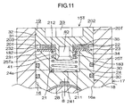
- FIG. 11 is a sectional view that illustrates a rack guide unit 15T according to a sixth embodiment of the invention.
- the configuration in the sixth embodiment illustrated in FIG. 11 differs from that in the fifth embodiment illustrated in FIG. 9 mainly in the following point.
- the coned disc springs 22 and the compression coil spring 21 are disposed in parallel. Further, a part of the compression coil spring 21 is inserted in the recessed portion 40 of the hollow protrusion 25S of the closure member 20S.
- the coned disc springs 22 and the compression coil spring 21 are disposed in series with the seat plate 23 interposed therebetween. Further, an outer periphery 25Ta of a hollow protrusion 25T of a closure member 20T is radially opposed to the radially inner portions of the coned disc springs 22 and the seat plate 23. The protrusion 25T is inserted in the compression coil spring 21.
- the same components in the sixth embodiment illustrated in FIG. 11 as those in the fifth embodiment illustrated in FIG. 9 will be denoted by the same reference symbols as those in the fifth embodiment illustrated in FIG. 9 .
- the sixth embodiment produces the same advantageous effects as those of the fifth embodiment.
- the invention is not limited to the above-described embodiments.
- a ring having a rectangular sectional shape (not illustrated) may be used instead of the O-ring used as the elastic member serving as the retaining protrusion.
- the invention may be implemented in various other embodiments within the scope of the appended claims.
Description
- The invention relates to a rack guide unit and a steering system including the rack guide unit.
- Generally, a rack-and-pinion-type steering system is provided with a rack guide unit that reduces a backlash between a rack and a pinion. In the rack guide unit, when a rack guide by which a rack shaft is slidably supported wears out, a compression coil spring interposed between the rack guide and a plug pushes the rack guide toward the rack shaft to compensate for a clearance between the rack guide and the plug.
- According to Japanese Patent Application Publication No.
11-43055 JP 11-43055 A - In
FIG. 4 inJP 11-43055 A JP 11-43055 A - According to the technique described in
JP 11-43055 A - This affects the efficiency of assembly of the rack guide unit.
- A rack guide unit having the features of the preamble of claim 1 is known, for example, from
FR 1 327 797 A GB 976 661 A - One object of the invention is to provide a rack guide unit that is assembled with ease as a whole, and to provide a steering system including the rack guide unit.
- A rack guide unit according to an aspect of the invention includes: a rack guide accommodated in an accommodation portion formed in a housing through which a rack shaft meshed with a pinion shaft is passed, so as to be allowed to approach and move away from the rack shaft, the rack guide supporting the rack shaft such that the rack shaft is slidable in an axial direction of the rack shaft; a closure member secured to an external opening end of the accommodation portion, the external opening end being located on an opposite side of the accommodation portion from the rack shaft; at least one coned disc spring that is interposed between the closure member and the rack guide, and that urges the rack guide toward the rack shaft; a recessed portion formed in an opposed portion of the rack guide, the opposed portion being opposed to the closure member; a protrusion that is formed on the closure member, passed though the coned disc spring, and inserted in the recessed portion; and a retaining protrusion formed integrally with an outer periphery of the protrusion or formed separately from the protrusion and attached to the outer periphery of the protrusion, and located at a position closer to a distal end of the protrusion than the coned disc spring is, the retaining protrusion restraining the coned disc spring from coming off the protrusion.
- The foregoing and further features and advantages of the invention will become apparent from the following description of example embodiments with reference to the accompanying drawings, wherein like numerals are used to represent like elements and wherein:
-
FIG. 1 is a view schematically illustrating the configuration of a rack-and-pinion-type steering system according to a first embodiment of the invention; -
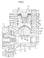
FIG. 2 is a sectional view illustrating main portions of the steering system including a rack guide unit according to the first embodiment; -
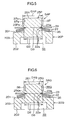
FIG. 3 is an enlarged sectional view of the rack guide unit according to the first embodiment; -
FIG. 4 is a sectional view of a subassembly formed in advance before the rack guide unit is assembled in the first embodiment, the subassembly including, for example, coned disc springs, an O-ring that may function as an elastic member constituting a retaining protrusion, and a closure member; -
FIG. 5 is a sectional view of a subassembly formed in advance before a rack guide unit is assembled in a second embodiment of the invention, the subassembly including, for example, coned disc springs, a rolled bushing that may function as an elastic member constituting a retaining protrusion, and a closure member; -
FIG. 6 is a sectional view of a subassembly formed in advance before a rack guide unit is assembled in a third embodiment of the invention, the subassembly including, for example, coned disc springs, a plurality of elastic bars that may function as elastic members constituting retaining protrusions, and a closure member; -
FIG. 7 is a sectional view of a rack guide unit according to a fourth embodiment of the invention; -
FIG. 8 is a sectional view of a subassembly formed in advance before the rack guide unit is assembled in the fourth embodiment, the subassembly including, for example, coned disc springs, a retaining ring constituting a retaining protrusion, and a closure member; -
FIG. 9 is a sectional view of a rack guide unit according to a fifth embodiment of the invention; -
FIG. 10 is a sectional view of a subassembly formed in advance before the rack guide unit is assembled in the fifth embodiment, the subassembly including, for example, coned disc springs, and a closure member with a plastically deformed protrusion that constitutes a retaining protrusion; and -
FIG. 11 is a sectional view of a rack guide unit according to a sixth embodiment of the invention. - Hereinafter, example embodiments of the invention will be described with reference the accompanying drawings.
FIG. 1 is a schematic view illustrating the configuration of a steering system 1 to which arack guide unit 15 according to a first embodiment of the invention is applied. As illustrated inFIG. 1 , the steering system 1 includes asteering shaft 3, anintermediate shaft 5, apinion shaft 7 and arack shaft 8. Thesteering shaft 3 is coupled to asteering member 2 such as a steering wheel. Theintermediate shaft 5 is coupled to thesteering shaft 3 via auniversal joint 4. Thepinion shaft 7 is coupled to theintermediate shaft 5 via auniversal joint 6. Therack shaft 8 has arack 8a that is meshed with apinion 7a provided on thepinion shaft 7 at a position near one end of thepinion shaft 7. Therack shaft 8 serves as a steered shaft extending in the lateral direction of a vehicle. Thepinion shaft 7 and therack shaft 8 constitute a rack-and-pinion mechanism A that serves as a steering mechanism. - The
rack shaft 8 is held via a plurality of bearings (not illustrated) by a rack housing 9 secured to a vehicle body so as to be allowed to make a linear reciprocating motion along an axial direction Z1. Opposite end portions of therack shaft 8 protrude on the opposite sides from the rack housing 9, andtie rods 10 are respectively coupled to the opposite end portions of therack shaft 8. Thetie rods 10 are linked to corresponding steeredwheels 11 via corresponding knuckle arms (not illustrated). - When the
steering shaft 3 is rotated in response to an operation of thesteering member 2, the rotation of thesteering shaft 3 is converted into a linear motion of therack shaft 8 in the axial direction Z1 by thepinion 7a and therack 8a. Thus, the steeredwheels 11 are steered. As illustrated inFIG. 2 that is a sectional view of main portions of the steering system 1, thepinion shaft 7 is rotatably held by a first bearing 12 and a second bearing 13 in apinion housing 14. The first bearing 12 is, for example, a ball bearing, and the second bearing 13 is, for example, a cylindrical roller bearing. Thepinion 7a of thepinion shaft 7 and therack 8a of therack shaft 8 are meshed with each other in thepinion housing 14. - The steering system 1 includes the
rack guide unit 15 according to the first embodiment. Therack guide unit 15 includes ahousing 17 and arack guide 18. Thehousing 17 defines anaccommodation portion 16 that is a circular hole through which therack shaft 8 is passed. Therack guide 18 is accommodated in theaccommodation portion 16 so as to be allowed to approach and move away from therack shaft 8. Aback side 8b of therack shaft 8, which is on the opposite side of therack shaft 8 from therack 8a, is slidably supported by therack guide 18. Therack guide unit 15 includes aclosure member 20, acompression coil spring 21, at least one coned disc spring 22 (in the invention, a plurality ofconed disc springs 22 is provided), and anannular seat plate 23. Theclosure member 20 is a plug fitted to anexternal opening end 19 of theaccommodation portion 16. Theexternal opening end 19 is located on the opposite side of theaccommodation portion 16 from therack shaft 8. Thecompression coil spring 21 and theconed disc springs 22 are interposed between therack guide 18 and theclosure member 20. Theseat plate 23 is interposed between theconed disc springs 22 and therack guide 18 so as to receive a load from theconed disc springs 22. - The
rack guide unit 15 includes arecessed portion 24, acolumnar protrusion 25 and an O-ring 26. Therecessed portion 24 is formed in therack guide 18. Theprotrusion 25 is formed on theclosure member 20, passed through theconed disc springs 22 and theseat plate 23, and inserted in the recessedportion 24. The O-ring 26 is an elastic member that is held by anouter periphery 25a of theprotrusion 25, at a position closer to the distal end of theprotrusion 25 than theseat plate 23 is, and that may function as a retaining protrusion. The O-ring 26 (elastic member), which may function as the retaining protrusion, has the function of restraining the coned disc springs 22 and theseat plate 23 from coming off theprotrusion 25. The O-ring 26 is frictionally engaged with aninner periphery 24a (cylindrical face) of the recessedportion 24, and applies a frictional resistance load to therack guide 18 when therack guide 18 is moved toward theclosure member 20 by an input load from therack shaft 8 side. - The
housing 17 of therack guide unit 15 and thepinion housing 14 are made of the same material and formed as a single-piece member. Thehousing 17 is disposed on the opposite side of therack shaft 8 from thepinion shaft 7. Thepinion housing 14 and thehousing 17 are formed by, for example, die casting. Therack guide 18 has afirst face 181, asecond face 182, and an outerperipheral face 183 that is a cylindrical face. Thefirst face 181 is opposed to therack shaft 8. Thesecond face 182 is located on the opposite side of therack guide 18 from thefirst face 181. Aconcave face 27 having a shape that conforms to the shape of theback side 8b of therack shaft 8 is formed in thefirst face 181 of therack guide 18. A curved slidingplate 28 is attached to theconcave face 27 so as to conform to theconcave face 27. The slidingplate 28 is in sliding contact with theback side 8b of therack shaft 8. Preferably, a plate having a low frictional coefficient is used as the slidingplate 28. For example, a metal plate or a metal plate coated with a fluorine resin may be used as the slidingplate 28. - Annular
elastic members 30 such as O-rings are respectively accommodated and held in multipleannular accommodation grooves 29 formed in the outerperipheral face 183 of therack guide 18. Therack guide 18 has an outer diameter that is slightly smaller than the inner diameter of theaccommodation portion 16. As theelastic members 30 slide on aninner periphery 16a of theaccommodation portion 16, therack guide 18 moves in theaccommodation portion 16 in such directions as to approach and move away from therack shaft 8. Theelastic members 30 has the function of restraining therack guide 18 from tilting within theaccommodation portion 16. - As illustrated in
FIG. 3 that is an enlarged view of part ofFIG. 2 , the recessedportion 24 is ,for example, a circular central hole formed in thesecond face 182 of therack guide 18, and accommodates thecompression coil spring 21. Afirst end portion 211 of thecompression coil spring 21 is received by abottom 241 of the recessedportion 24. Theinner periphery 24a of the recessedportion 24 has the function of guiding radially outer portions of thecompression coil spring 21. As illustrated inFIG. 2 andFIG. 3 , theclosure member 20 is a plug that has afirst face 201 and asecond face 202. Thefirst face 201 is opposed to thesecond face 182 of therack guide 18. Thesecond face 202 is located on the opposite side of theclosure member 20 from thefirst face 201. Theclosure member 20 has anexternal thread 31 formed on itsouter periphery 203. In addition, aninternal thread 32 is formed in theinner periphery 16a ofaccommodation portion 16, within a range from the external openingend 19 to a position that is apart from the external openingend 19 by a prescribed distance. Theexternal thread 31 of theclosure member 20 is screwed to theinternal thread 32 to secure theclosure member 20 to thehousing 17. Atool engagement hole 33 having a polygonal sectional shape (for example, a hexagonal sectional shape), in which a tool for screwing theclosure member 20 to thehousing 17 is engaged, is formed in thesecond face 202 of theclosure member 20. - The
protrusion 25 is formed on thefirst face 201 of theclosure member 20, and is inserted in the recessedportion 24. Thecompression coil spring 21 is interposed, in a compressed state, between anend face 251 of theprotrusion 25 of theclosure member 20 and thebottom 241 of the recessedportion 24 of therack guide 18, and elastically urges therack guide 18 toward therack shaft 8. The outer periphery of theprotrusion 25 serves as a guide for radiallyinner portions 22a of the coned disc springs 22. - An
annular seat face 34 that surrounds the recessedportion 24 is formed in thesecond face 182 of therack guide 18. Theclosure member 20 has anannular seat face 35 that surrounds theprotrusion 25 and that is opposed to theseat face 34. The coned disc springs 22 and theseat plate 23 are interposed between the seat faces 34, 35. Theseat plate 23 is disposed along theseat face 34 of therack guide 18. That is, theseat plate 23 has afirst face 231 and asecond face 232. Thefirst face 231 extends along theseat face 34 of therack guide 18. Thesecond face 232 serves as a seat face that receives a load from the coned disc springs 22. The distance between thesecond face 232 of theseat plate 23 and theseat face 35 is set greater than the length of the plurality of coned disc springs 22 when the coned disc springs 22 are in closed contact with each other. - For example, when the
rack guide 18 is made of aluminum, theseat plate 23 has the function of restraining abrasion of theseat face 34 of therack guide 18 by preventing theseat face 34 of therack guide 18 from making contact with the coned disc springs 22. Therefore, theseat plate 23 is made of, for example, steel or resin. Theouter periphery 25a of theprotrusion 25 of theclosure member 20 and theinner periphery 24a of the recessedportion 24 serve as opposed portions that are opposed to each other with a predetermined gap left therebetween. The O-ring 26 (elastic member) is held in anaccommodation groove 36 formed in theouter periphery 25a of theprotrusion 25, and is frictionally engaged with theinner periphery 24a (opposed portion) of the recessedportion 24. The O-ring 26 may be elastically compressed between theinner periphery 24a of the recessedportion 24 and theouter periphery 25a of theprotrusion 25. However, O-ring 26 need not be elastically compressed between theinner periphery 24a of the recessedportion 24 and theouter periphery 25a of theprotrusion 25 - As illustrated in
FIG. 4 , the coned disc springs 22, theseat plate 23, the O-ring 26 (elastic member) and theclosure member 20 constitute a subassembly SA that is assembled in advance before therack guide 15 is assembled and that can be handled as one unit body. Specifically, the coned disc springs 22 and theseat plate 23 are disposed so as to surround theprotrusion 25, and the O-ring 26 is held in theaccommodation groove 36 formed at a position located closer to the distal end of theprotrusion 25 than the coned disc springs 22 and theseat plate 23 are. - In the state of the subassembly SA, part of the O-
ring 26 is overlapped with part of the coned disc springs 22 as viewed from the axial direction of theprotrusion 25. That is, an outer diameter D1 of the annular O-ring 26 held in theaccommodation groove 36 of theprotrusion 25 is set larger than an inner diameter D2 of the coned disc springs 22 and an inner diameter D3 of the seat plate 23 (D1 > D2, D1 > D3). Thus, the O-ring 26 restrains the coned disc springs 22 and theseat plate 23 from coming off theprotrusion 25. - According to the first embodiment, the retaining protrusion (O-
ring 26 as an elastic member) disposed on theouter periphery 25a of theprotrusion 25 of theclosure member 20 restrains the coned disc springs 22 from coming off theprotrusion 25. Thus, before therack guide unit 15 is assembled, the coned disc springs 22 are held on theclosure member 20 to assemble the coned disc springs 22 and theclosure member 20 into the subassembly SA. Thus, it is possible to enhance the efficiency of assembly of therack guide unit 15 as a whole. - The elastic member (O-ring 26) is easily fitted in the
accommodation groove 36 formed in theouter periphery 25a of theprotrusion 25, and thus the elastic member (O-ring 26) constitutes the retaining protrusion. Thus, it is possible to assemble therack guide unit 15 with ease. Further, the elastic member (O-ring) 26 that constitutes the retaining protrusion is frictionally engaged with theinner periphery 24a of the recessedportion 24 in therack guide 18. Thus, the elastic member (O-ring 26) applies a frictional resistance load that is superposed on a reaction load from the coned disc springs 22 to resist against displacement of therack guide 18 caused by a load input from therack shaft 8 side. Thus, it is possible to enhance a counteracting load against a reversed input load from therack shaft 8 side. - Further, the
annular seat plate 23 that bears a load from the coned disc springs 22 is interposed between the coned disc springs 22 and (theseat face 34 of) therack guide 18. Thus, the coned disc springs 22 and therack guide 18 are prevented from making contact with each other. Thus, it is possible to restrain abrasion of (theseat face 34 of) therack guide 18. Moreover, the retaining protrusion (O-ring 26) restrains theseat plate 23 from coming off theprotrusion 25. Thus, before therack guide unit 15 is assembled, the coned disc springs 22, theseat plate 23 and theclosure member 20 are assembled into the sub-assembly. Thus, it is possible to enhance the efficiency of assembly of therack guide unit 15 as a whole. Further, with the use of thecompression coil spring 21 in addition to the coned disc springs 22, the flexibility in setting the load is enhanced. -
FIG. 5 illustrates a subassembly SAP in a rack guide unit according to a second embodiment of the invention. As illustrated inFIG. 5 , the configuration in the second embodiment differs from the configuration in the first embodiment inFIG. 4 mainly in the following point. In the first embodiment, the O-ring 26 is used as the elastic member that constitutes the retaining protrusion. - On the other hand, in the subassembly SAP in the second embodiment illustrated in
FIG. 5 , as the elastic member constituting the retaining protrusion, there is used a rolledbushing 37 that is held on an outer periphery 25Pa of aprotrusion 25P of aclosure member 20P by press-fitting. Aninner periphery 37b of the rolledbushing 37 is fitted on the outer periphery 25Pa of theprotrusion 25P by press-fitting. If theouter periphery 37a of the rolledbushing 37 is frictionally engageable with the inner periphery of a recessed portion of a rack guide (corresponding to theinner periphery 24a of the recessedportion 24 of therack guide 18 in the first embodiment illustrated inFIG. 3 ), theouter periphery 37a of the rolledbushing 37 may be formed of a metal layer serving as a frictionally engaging layer. If theouter periphery 37a of the rolledbushing 37 is formed of a resin layer that serves as a frictionally engaging layer having radial elasticity, the rolledbushing 37 may serve as the elastic member. - Although not illustrated in
FIG. 5 , theouter periphery 37a of the rolledbushing 37 is frictionally engaged with the inner periphery of the recessed portion of the rack guide. An outer diameter D1P of the rolledbushing 37 held on the outer periphery 25Pa of theprotrusion 25P is set larger than the inner diameter D2 of the coned disc springs 22 and the inner diameter D3 of the seat plate 23 (D1P > D2, D1P > D3). Thus, the rolledbushing 37 restrains the coned disc springs 22 and theseat plate 23 from coming off theprotrusion 25P. - The same components in the second embodiment illustrated in
FIG. 5 as those in the first embodiment illustrated inFIG. 4 will be denoted by the same reference symbols as those in the first embodiment illustrated inFIG. 4 . The second embodiment produces the same advantageous effects as those of the first embodiment. By using the subassembly SAP that is assembled in advance before the rack guide unit is assembled, it is possible to enhance the efficiency of assembly of the rack guide unit. Although not illustrated inFIG. 5 , the rolledbushing 37 is frictionally engaged with the inner periphery of the recessed portion of the rack guide. Thus, the rolledbushing 37 applies a frictional resistance load to the rack guide against a reverse input load from the rack shaft side. As a result, it is possible to increase the counteracting force against the reverse input load. -
FIG. 6 illustrates a subassembly SAQ in a rack guide unit according to a third embodiment of the invention. As illustrated inFIG. 6 , the configuration in the third embodiment differs from the configuration in the first embodiment inFIG. 4 mainly in the following point. In the first embodiment, the O-ring 26 is used as the elastic member that constitutes the retaining protrusion. - On the other hand, in the subassembly SAQ in the third embodiment illustrated in
FIG. 9 , as the elastic member that constitutes the retaining protrusion, non-annular members are used. Specifically, as the elastic member, multipleelastic bars 38 that are made of rubber or resin and that extend in the height direction of aprotrusion 25Q of aclosure member 20Q are arranged at equal intervals in a circumferential direction K1 of theprotrusion 25Q.Accommodation grooves 36Q extending in the height direction of theprotrusion 25Q are formed in an outer periphery 25Qa of theprotrusion 25Q so as to be arranged at equal intervals in the circumferential direction K1, and theelastic bars 38 are respectively fitted in theaccommodation grooves 36Q. Displacement of theelastic bars 38 held in theaccommodation grooves 36Q in the height direction of theprotrusion 25Q is restricted. - A diameter D1Q of a circle that is circumscribed to the multiple
elastic bars 38 is set larger than the inner diameter D2 of the coned disc springs 22 and the inner diameter D3 of the seat plate 23 (DQ1 > D2, DQ1 > D3). Thus, the multipleelastic bars 38 restrain the coned disc springs 22 and theseat plate 23 from coming off theprotrusion 25Q. The same components in the third embodiment illustrated inFIG. 6 as those in the first embodiment illustrated inFIG. 4 will be denoted by the same reference symbols as those in the first embodiment illustrated inFIG. 4 . The third embodiment produces the same advantageous effects as those of the first embodiment. By using the subassembly SAQ that is assembled in advance before the rack guide unit is assembled, it is possible to enhance the efficiency of assembly of the rack guide unit. Although not illustrated inFIG. 6 , the multipleelastic bars 38 are frictionally engaged with the inner periphery of the recessed portion of the rack guide. Thus, theelastic bars 38 apply a frictional resistance load to the rack guide against a reverse input load from the rack shaft side. As a result, it is possible to increase the counteracting force against the reverse input load. -
FIG. 7 is a sectional view that illustrates arack guide unit 15R according to a fourth embodiment of the invention.FIG. 8 is a sectional view that illustrates a subassembly SAR that is assembled in advance before therack guide unit 15R in the fourth embodiment is assembled. The configuration of therack guide unit 15R in the fourth embodiment illustrated inFIG. 7 differs from that of therack guide unit 15 in the first embodiment illustrated inFIG. 3 mainly in the following point. In the first embodiment illustrated inFIG. 3 , the O-ring 26 (elastic member) held in theaccommodation groove 36 formed in theouter periphery 25a of thesolid protrusion 25 is used as the retaining protrusion. The O-ring 26 is frictionally engaged with theinner periphery 24a of the recessedportion 24 to impose a frictional resistance against the displacement of therack guide 18. - On the other hand, in the
rack guide unit 15R in the fourth embodiment illustrated inFIG. 7 , a C-shapedretaining ring 39 that is held in anaccommodation groove 36R formed in an outer periphery 25Ra of aprotrusion 25R of aclosure member 20R is used as the retaining protrusion. The retainingring 39 is not engaged with theinner periphery 24a of the recessedportion 24. The retainingring 39 may have a rectangular sectional shape as illustrated inFIG. 7 , or a rounded sectional shape such as a circular sectional shape. - The
protrusion 25R is hollow. That is, a recessedportion 40 is formed in anend face 251R of theprotrusion 25R. Part of thecompression coil spring 21 is disposed in the recessedportion 40 of theprotrusion 25R. Asecond end portion 212 of thecompression coil spring 21 is received at a bottom 401 of the recessedportion 40. Aninner periphery 40a of the recessedportion 40 serves as a radially outer portion guide that guides the radially outer portions of the part of thecompression coil spring 21. - As illustrated in
FIG. 8 , before therack guide unit 15R is assembled, the subassembly SAR including the coned disc springs 22, theseat plate 23, the retainingring 39 and theclosure member 20R is formed in advance. An outer diameter D1R of the C-shapedretaining ring 39 held in theaccommodation groove 36 formed in theprotrusion 25R of theclosure member 20R is set larger than the inner diameter D2 of the coned disc springs 22 and the inner diameter D3 of the seat plate 23 (D1R > D2, D1R > D3). Thus, the retainingring 39 restrains the coned disc springs 22 and theseat plate 23 from coming off theprotrusion 25R. - The same components in the fourth embodiment illustrated in
FIG. 7 and FIG. 8 as those in the first embodiment illustrated inFIG. 3 and FIG. 4 will be denoted by the same reference symbols as those in the first embodiment illustrated inFIG. 3 and FIG. 4 . The fourth embodiment produces the same advantageous effects as those of the first embodiment. By using the subassembly SAR that is assembled in advance before the rack guide unit is assembled, it is possible to enhance the efficiency of assembly of the rack guide unit. By using the C-shapedretaining ring 39 that is an inexpensive general purpose article as the retaining protrusion, the manufacturing cost is reduced. The retainingring 39 is not frictionally engaged with theinner periphery 24a of the recessedportion 24 of therack guide 18, and thus does not apply a frictional resistance load to therack guide 18. -
FIG. 9 is a sectional view that illustrates arack guide unit 15S according to a fifth embodiment of the invention.FIG. 10 is a sectional view that illustrates a subassembly SAS that is assembled in advance before therack guide unit 15S in the fifth embodiment is assembled. Therack guide unit 15S in the fifth embodiment illustrated inFIG. 9 differs from therack guide unit 15R in the fourth embodiment illustrated inFIG. 7 mainly in the following point. In the fourth embodiment illustrated inFIG. 7 , the C-shapedretaining ring 39 held in theaccommodation groove 36R formed in the outer periphery 25Ra of theprotrusion 25R of theclosure member 20R is used as the retaining protrusion. - On the other hand, in the
rack guide unit 15S in the fifth embodiment illustrated inFIG. 9 , a plasticallydeformed protrusion 41 formed by plastically deforming, for example, the distal end portion of acylindrical protrusion 25S of theclosure member 20S outward in the radial direction is used as the retaining protrusion. The plasticallydeformed protrusion 41 may be an annular protrusion formed around the entire outer periphery 25Sa of theprotrusion 25S or may be formed of protrusions formed at multiple positions along the circumferential direction of the outer periphery 25Sa of theprotrusion 25S. - As illustrated in
FIG. 10 , before therack guide unit 15S is assembled, the subassembly SAS is prepared in advance. The subassembly SAS includes the coned disc springs 22, theseat plate 23 and theclosure member 20S. Theclosure member 20S has the plastically deformed protrusion 41 (retaining protrusion). Specifically, the coned disc springs 22 and theseat plate 23 are fitted onto a protrusion of a workpiece that will be manufactured into the closure member before the plasticallydeformed protrusion 41 is formed, and then the plasticallydeformed protrusion 41 is formed. In this way, the subassembly SAS is assembled. - An outer diameter D1S of the plastically
deformed protrusion 41 of theclosure member 20S is set larger than the inner diameter D2 of the coned disc springs 22 and the inner diameter D3 of the seat plate 23 (D1S > D2, D1S > D3). Thus, with the plasticallydeformed protrusion 41, the coned disc springs 22 and theseat plate 23 are restrained from coming off theprotrusion 25S. The same components in the fifth embodiment illustrated inFIG. 9 and FIG. 10 as those in the fourth embodiment illustrated inFIG. 7 and FIG. 8 will be denoted by the same reference symbols as those in the fourth embodiment illustrated inFIG. 7 and FIG. 8 . The fifth embodiment produces the same advantageous effects as those of the fourth embodiment. By using the subassembly SAS that is assembled in advance before the rack guide unit is assembled, it is possible to enhance the efficiency of assembly of the rack guide unit. Further, because the retaining protrusion is formed of the plasticallydeformed protrusion 41 formed integrally with theprotrusion 25S from the same material, the number of components is reduced. Thus, it is possible to reduce the manufacturing cost. -
FIG. 11 is a sectional view that illustrates arack guide unit 15T according to a sixth embodiment of the invention. The configuration in the sixth embodiment illustrated inFIG. 11 differs from that in the fifth embodiment illustrated inFIG. 9 mainly in the following point. In the fifth embodiment illustrated inFIG. 9 , the coned disc springs 22 and thecompression coil spring 21 are disposed in parallel. Further, a part of thecompression coil spring 21 is inserted in the recessedportion 40 of thehollow protrusion 25S of theclosure member 20S. - On the other hand, in the
rack guide unit 15T in the sixth embodiment illustrated inFIG. 11 , the coned disc springs 22 and thecompression coil spring 21 are disposed in series with theseat plate 23 interposed therebetween. Further, an outer periphery 25Ta of ahollow protrusion 25T of aclosure member 20T is radially opposed to the radially inner portions of the coned disc springs 22 and theseat plate 23. Theprotrusion 25T is inserted in thecompression coil spring 21. The same components in the sixth embodiment illustrated inFIG. 11 as those in the fifth embodiment illustrated inFIG. 9 will be denoted by the same reference symbols as those in the fifth embodiment illustrated inFIG. 9 . The sixth embodiment produces the same advantageous effects as those of the fifth embodiment. By using a subassembly (not illustrated) that is assembled in advance before the rack guide unit is assembled, it is possible to enhance the efficiency of assembly of the rack guide unit. Further, because the coned disc springs 22 and thecompression coil spring 21 are disposed in series, it is possible enhance the flexibility in setting a load for urging therack guide 18. - The invention is not limited to the above-described embodiments. For example, instead of the O-ring used as the elastic member serving as the retaining protrusion, a ring having a rectangular sectional shape (not illustrated) may be used. Further, the invention may be implemented in various other embodiments within the scope of the appended claims.
Claims (8)
- A rack guide unit (15; 15R-15T) comprising:a rack guide (18) accommodated in an accommodation portion (16) formed in a housing (9) through which a rack shaft (8) meshed with a pinion shaft (7) is passed, so as to be allowed to approach and move away from the rack shaft (8), the rack guide (18) supporting the rack shaft (8) such that the rack shaft (8) is slidable in an axial direction of the rack shaft (8);a closure member (20) secured to an external opening end (19) of the accommodation portion (16), the external opening end (19) being located on an opposite side of the accommodation portion (16) from the rack shaft (8);at least one coned disc spring (22) that is interposed between the closure member (20) and the rack guide (18), and that urges the rack guide (18) toward the rack shaft (8);a recessed portion (24) formed in an opposed portion (24a) of the rack guide (18), the opposed portion (24a) being opposed to the closure member (20); anda protrusion (25; 25P-25T) that is formed on the closure member (20), passed though the coned disc spring (22), and inserted in the recessed portion (24), characterized in comprising a retaining protrusion (26; 37; 38; 39; 41) formed integrally with an outer periphery (25a; 25Pa-25Ta) of the protrusion (25; 25P-25T) or formed separately from the protrusion (25; 25P-25T) and attached to the outer periphery (25a; 25Pa-25Ta) of the protrusion (25; 25P-25T), and located at a position closer to a distal end of the protrusion (25; 25P-25T) than the coned disc spring (22) is, the retaining protrusion (26; 37; 38; 39; 41) restraining the coned disc spring (22) from coming off the protrusion (25; 25P-25T).
- The rack guide unit (15; 15R) according to claim 1, wherein the retaining protrusion (26; 37; 38; 39) is an elastic member (26; 37; 38; 39) supported on the outer periphery (25a; 25Pa-25Ra) of the protrusion (25; 25P- 25R).
- The rack guide unit (15) according to claim 2, wherein the elastic member (26; 37; 38) is frictionally engaged with an inner periphery (24a) of the recessed portion (24).
- The rack guide unit (15R) according to claim 2, wherein the retaining protrusion is a C-shaped retaining ring (39) held in an accommodation groove formed in the outer periphery (25Ra) of the protrusion (25R).
- The rack guide unit (15S;15T) according to claim 1, wherein the retaining protrusion is a plastically deformed protrusion (41) formed integrally with the protrusion (25S; 25T) and made of the same material as that of the protrusion (25S; 25T).
- The rack guide unit (15; 15R-15T) according to any one of claims 1 to 5, wherein:an annular seat plate (23) is interposed between the coned disc spring (22) and the rack guide (18) to receive a load from the coned disc spring (22); andthe retaining protrusion (26; 37; 38; 39; 41) restrains the seat plate from coming off the protrusion (25; 25P-25S).
- The rack guide unit (15; 15R-15T) according to any one of claims 1 to 6, wherein a compression coil spring (21) is interposed between the rack guide (18) and the closure member (20) to urge the rack guide (18) toward the rack shaft (8).
- The rack guide unit (15; 15R-15T) according to claim 7, wherein the recessed portion (24) has a cylindrical shape so as to guide radially outer portions of the compression coil spring (21).
Applications Claiming Priority (1)
| Application Number | Priority Date | Filing Date | Title |
|---|---|---|---|
| JP2013104205A JP6112350B2 (en) | 2013-05-16 | 2013-05-16 | Rack guide device and steering device including the same |
Publications (2)
| Publication Number | Publication Date |
|---|---|
| EP2803554A1 EP2803554A1 (en) | 2014-11-19 |
| EP2803554B1 true EP2803554B1 (en) | 2016-06-22 |
Family
ID=50687365
Family Applications (1)
| Application Number | Title | Priority Date | Filing Date |
|---|---|---|---|
| EP14168082.7A Not-in-force EP2803554B1 (en) | 2013-05-16 | 2014-05-13 | Rack guide unit and steering system including the rack guide unit |
Country Status (4)
| Country | Link |
|---|---|
| US (1) | US9157513B2 (en) |
| EP (1) | EP2803554B1 (en) |
| JP (1) | JP6112350B2 (en) |
| CN (1) | CN104163194B (en) |
Families Citing this family (10)
| Publication number | Priority date | Publication date | Assignee | Title |
|---|---|---|---|---|
| KR101209326B1 (en) * | 2011-06-20 | 2012-12-06 | 주식회사 만도 | Rack bar supporting device of steering apparatus for vehicle |
| DE202012100803U1 (en) * | 2012-03-07 | 2012-04-03 | Trumpf Werkzeugmaschinen Gmbh + Co. Kg | Device for backlash adjustment and linear drive |
| JP6137537B2 (en) * | 2013-05-16 | 2017-05-31 | 株式会社ジェイテクト | Rack guide device and steering device including the same |
| JP2016128311A (en) * | 2015-01-09 | 2016-07-14 | 株式会社ショーワ | Rack guide mechanism |
| JP2016141190A (en) * | 2015-01-30 | 2016-08-08 | 株式会社ショーワ | Rack guide mechanism |
| JP2016141343A (en) * | 2015-02-04 | 2016-08-08 | 富士重工業株式会社 | Steering device |
| JP6528482B2 (en) * | 2015-03-17 | 2019-06-12 | 株式会社ジェイテクト | Rack shaft and steering device |
| JP2016210320A (en) * | 2015-05-11 | 2016-12-15 | 株式会社ジェイテクト | Rack guide device |
| KR101858391B1 (en) * | 2017-03-08 | 2018-05-15 | 주식회사 만도 | Rack Bar Supporting Device of Steering Apparatus for Vehicle |
| JP7206651B2 (en) * | 2018-07-03 | 2023-01-18 | 日本精工株式会社 | Rack and pinion type steering gear unit |
Family Cites Families (21)
| Publication number | Priority date | Publication date | Assignee | Title |
|---|---|---|---|---|
| GB976661A (en) | 1960-03-02 | 1964-12-02 | Cam Gears Ltd | A new or improved rack and pinion steering gear |
| FR1327797A (en) | 1962-03-22 | 1963-05-24 | Eng Productions Clevedon Ltd | Rack and pinion steering mechanism for vehicles |
| DE1262796B (en) * | 1965-09-18 | 1968-03-07 | Auto Union Gmbh | Steering device with rack and pinion, especially for motor vehicles |
| NL130474C (en) | 1966-05-13 | 1971-01-15 | ||
| JPH01174284U (en) * | 1988-05-30 | 1989-12-11 | ||
| JPH081208B2 (en) * | 1990-02-21 | 1996-01-10 | 三菱電機株式会社 | Stepped screw |
| JPH0939805A (en) * | 1995-07-27 | 1997-02-10 | Toyota Motor Corp | Rack pinion type steering device |
| JPH1143055A (en) | 1997-07-25 | 1999-02-16 | Nippon Seiko Kk | Steering device |
| JP4254380B2 (en) | 2003-06-27 | 2009-04-15 | 株式会社ジェイテクト | Steering device |
| DE102004053462A1 (en) * | 2004-11-05 | 2006-05-11 | Zf Lenksysteme Gmbh | Device for pressing a rack |
| JP2007062450A (en) * | 2005-08-29 | 2007-03-15 | Jtekt Corp | Rack shaft support device |
| JP4367432B2 (en) * | 2006-04-24 | 2009-11-18 | オイレス工業株式会社 | Rack and pinion type steering device |
| JP4994272B2 (en) * | 2008-03-05 | 2012-08-08 | 本田技研工業株式会社 | Rack and pinion steering system |
| US7930951B2 (en) * | 2008-03-07 | 2011-04-26 | Nexteer (Beijing) Technology Co., Ltd. | Rack and pinion steering gear with self-adjusting rack bearing |
| DE102010029603A1 (en) * | 2010-06-02 | 2011-12-08 | Zf Lenksysteme Gmbh | Device for pressing steering rack into gear pinion of steering of motor car, has adjustment device including washer disks, where complete adjustment device is pre-assembled as mounting unit with thrust piece, washer and spring by spring pin |
| US8714042B2 (en) * | 2010-06-14 | 2014-05-06 | Honda Motor Co., Ltd. | Controllable steering rack guide system and method |
| JP2012254780A (en) * | 2011-05-13 | 2012-12-27 | Nsk Ltd | Steering device |
| JP2012245811A (en) * | 2011-05-25 | 2012-12-13 | Nsk Ltd | Rack and pinion steering device |
| KR101146936B1 (en) * | 2011-10-28 | 2012-05-22 | 한국델파이주식회사 | Rack bar support device of steering gear |
| KR101206836B1 (en) * | 2012-03-14 | 2012-11-30 | 한국델파이주식회사 | rack bar support device of steering gear |
| US9657832B2 (en) * | 2013-03-11 | 2017-05-23 | Steering Solutions Ip Holding Corporation | Steering rack wear compensator assembly |
-
2013
- 2013-05-16 JP JP2013104205A patent/JP6112350B2/en not_active Expired - Fee Related
-
2014
- 2014-05-09 US US14/273,956 patent/US9157513B2/en not_active Expired - Fee Related
- 2014-05-13 EP EP14168082.7A patent/EP2803554B1/en not_active Not-in-force
- 2014-05-14 CN CN201410203341.9A patent/CN104163194B/en not_active Expired - Fee Related
Also Published As
| Publication number | Publication date |
|---|---|
| US9157513B2 (en) | 2015-10-13 |
| JP2014223860A (en) | 2014-12-04 |
| JP6112350B2 (en) | 2017-04-12 |
| CN104163194A (en) | 2014-11-26 |
| EP2803554A1 (en) | 2014-11-19 |
| CN104163194B (en) | 2017-10-31 |
| US20140338486A1 (en) | 2014-11-20 |
Similar Documents
| Publication | Publication Date | Title |
|---|---|---|
| EP2803554B1 (en) | Rack guide unit and steering system including the rack guide unit | |
| US9266556B2 (en) | Rack guide unit and steering system including the rack guide unit | |
| US8813904B2 (en) | Electric power steering system | |
| US8443929B2 (en) | Power steering apparatus | |
| EP2684771B1 (en) | Rack shaft supporting device and steering system using the same | |
| EP2687423B1 (en) | Rack shaft supporting device and vehicle steering system | |
| US10183693B2 (en) | Electric power steering device | |
| EP3093530B1 (en) | Rack guide unit | |
| JP6179347B2 (en) | Vehicle steering device | |
| JP6132147B2 (en) | Rack guide device | |
| US10202142B2 (en) | Rack guide device and steering apparatus including same | |
| EP3372475B1 (en) | Rack guide device | |
| JP6086233B2 (en) | Rack guide device and steering device including the same | |
| JP6137533B2 (en) | Rack guide device and steering device including the same | |
| JP2017013648A (en) | Rack guide device | |
| JP7274338B2 (en) | steering device | |
| EP2842834B1 (en) | Rack shaft supporting structure | |
| JP5954574B2 (en) | Rack shaft support device and steering device using the same | |
| JP2017001623A (en) | Rack guide device |
Legal Events
| Date | Code | Title | Description |
|---|---|---|---|
| PUAI | Public reference made under article 153(3) epc to a published international application that has entered the european phase |
Free format text: ORIGINAL CODE: 0009012 |
|
| 17P | Request for examination filed |
Effective date: 20140513 |
|
| AK | Designated contracting states |
Kind code of ref document: A1 Designated state(s): AL AT BE BG CH CY CZ DE DK EE ES FI FR GB GR HR HU IE IS IT LI LT LU LV MC MK MT NL NO PL PT RO RS SE SI SK SM TR |
|
| AX | Request for extension of the european patent |
Extension state: BA ME |
|
| RIN1 | Information on inventor provided before grant (corrected) |
Inventor name: TAENAKA, MAKOTO Inventor name: KAWAKUBO, AKITAKE |
|
| R17P | Request for examination filed (corrected) |
Effective date: 20150515 |
|
| RBV | Designated contracting states (corrected) |
Designated state(s): AL AT BE BG CH CY CZ DE DK EE ES FI FR GB GR HR HU IE IS IT LI LT LU LV MC MK MT NL NO PL PT RO RS SE SI SK SM TR |
|
| GRAP | Despatch of communication of intention to grant a patent |
Free format text: ORIGINAL CODE: EPIDOSNIGR1 |
|
| INTG | Intention to grant announced |
Effective date: 20151218 |
|
| GRAS | Grant fee paid |
Free format text: ORIGINAL CODE: EPIDOSNIGR3 |
|
| GRAA | (expected) grant |
Free format text: ORIGINAL CODE: 0009210 |
|
| RIN1 | Information on inventor provided before grant (corrected) |
Inventor name: KAWAKUBO, AKITAKE Inventor name: TAENAKA, MAKOTO |
|
| AK | Designated contracting states |
Kind code of ref document: B1 Designated state(s): AL AT BE BG CH CY CZ DE DK EE ES FI FR GB GR HR HU IE IS IT LI LT LU LV MC MK MT NL NO PL PT RO RS SE SI SK SM TR |
|
| REG | Reference to a national code |
Ref country code: GB Ref legal event code: FG4D |
|
| REG | Reference to a national code |
Ref country code: CH Ref legal event code: EP |
|
| REG | Reference to a national code |
Ref country code: IE Ref legal event code: FG4D |
|
| REG | Reference to a national code |
Ref country code: AT Ref legal event code: REF Ref document number: 807481 Country of ref document: AT Kind code of ref document: T Effective date: 20160715 |
|
| REG | Reference to a national code |
Ref country code: DE Ref legal event code: R096 Ref document number: 602014002376 Country of ref document: DE |
|
| REG | Reference to a national code |
Ref country code: LT Ref legal event code: MG4D |
|
| REG | Reference to a national code |
Ref country code: NL Ref legal event code: MP Effective date: 20160622 |
|
| PG25 | Lapsed in a contracting state [announced via postgrant information from national office to epo] |
Ref country code: NO Free format text: LAPSE BECAUSE OF FAILURE TO SUBMIT A TRANSLATION OF THE DESCRIPTION OR TO PAY THE FEE WITHIN THE PRESCRIBED TIME-LIMIT Effective date: 20160922 Ref country code: FI Free format text: LAPSE BECAUSE OF FAILURE TO SUBMIT A TRANSLATION OF THE DESCRIPTION OR TO PAY THE FEE WITHIN THE PRESCRIBED TIME-LIMIT Effective date: 20160622 Ref country code: LT Free format text: LAPSE BECAUSE OF FAILURE TO SUBMIT A TRANSLATION OF THE DESCRIPTION OR TO PAY THE FEE WITHIN THE PRESCRIBED TIME-LIMIT Effective date: 20160622 |
|
| REG | Reference to a national code |
Ref country code: AT Ref legal event code: MK05 Ref document number: 807481 Country of ref document: AT Kind code of ref document: T Effective date: 20160622 |
|
| PG25 | Lapsed in a contracting state [announced via postgrant information from national office to epo] |
Ref country code: GR Free format text: LAPSE BECAUSE OF FAILURE TO SUBMIT A TRANSLATION OF THE DESCRIPTION OR TO PAY THE FEE WITHIN THE PRESCRIBED TIME-LIMIT Effective date: 20160923 Ref country code: LV Free format text: LAPSE BECAUSE OF FAILURE TO SUBMIT A TRANSLATION OF THE DESCRIPTION OR TO PAY THE FEE WITHIN THE PRESCRIBED TIME-LIMIT Effective date: 20160622 Ref country code: HR Free format text: LAPSE BECAUSE OF FAILURE TO SUBMIT A TRANSLATION OF THE DESCRIPTION OR TO PAY THE FEE WITHIN THE PRESCRIBED TIME-LIMIT Effective date: 20160622 Ref country code: RS Free format text: LAPSE BECAUSE OF FAILURE TO SUBMIT A TRANSLATION OF THE DESCRIPTION OR TO PAY THE FEE WITHIN THE PRESCRIBED TIME-LIMIT Effective date: 20160622 Ref country code: SE Free format text: LAPSE BECAUSE OF FAILURE TO SUBMIT A TRANSLATION OF THE DESCRIPTION OR TO PAY THE FEE WITHIN THE PRESCRIBED TIME-LIMIT Effective date: 20160622 Ref country code: NL Free format text: LAPSE BECAUSE OF FAILURE TO SUBMIT A TRANSLATION OF THE DESCRIPTION OR TO PAY THE FEE WITHIN THE PRESCRIBED TIME-LIMIT Effective date: 20160622 |
|
| PG25 | Lapsed in a contracting state [announced via postgrant information from national office to epo] |
Ref country code: IT Free format text: LAPSE BECAUSE OF FAILURE TO SUBMIT A TRANSLATION OF THE DESCRIPTION OR TO PAY THE FEE WITHIN THE PRESCRIBED TIME-LIMIT Effective date: 20160622 Ref country code: SK Free format text: LAPSE BECAUSE OF FAILURE TO SUBMIT A TRANSLATION OF THE DESCRIPTION OR TO PAY THE FEE WITHIN THE PRESCRIBED TIME-LIMIT Effective date: 20160622 Ref country code: IS Free format text: LAPSE BECAUSE OF FAILURE TO SUBMIT A TRANSLATION OF THE DESCRIPTION OR TO PAY THE FEE WITHIN THE PRESCRIBED TIME-LIMIT Effective date: 20161022 Ref country code: CZ Free format text: LAPSE BECAUSE OF FAILURE TO SUBMIT A TRANSLATION OF THE DESCRIPTION OR TO PAY THE FEE WITHIN THE PRESCRIBED TIME-LIMIT Effective date: 20160622 Ref country code: RO Free format text: LAPSE BECAUSE OF FAILURE TO SUBMIT A TRANSLATION OF THE DESCRIPTION OR TO PAY THE FEE WITHIN THE PRESCRIBED TIME-LIMIT Effective date: 20160622 Ref country code: EE Free format text: LAPSE BECAUSE OF FAILURE TO SUBMIT A TRANSLATION OF THE DESCRIPTION OR TO PAY THE FEE WITHIN THE PRESCRIBED TIME-LIMIT Effective date: 20160622 |
|
| PG25 | Lapsed in a contracting state [announced via postgrant information from national office to epo] |
Ref country code: AT Free format text: LAPSE BECAUSE OF FAILURE TO SUBMIT A TRANSLATION OF THE DESCRIPTION OR TO PAY THE FEE WITHIN THE PRESCRIBED TIME-LIMIT Effective date: 20160622 Ref country code: ES Free format text: LAPSE BECAUSE OF FAILURE TO SUBMIT A TRANSLATION OF THE DESCRIPTION OR TO PAY THE FEE WITHIN THE PRESCRIBED TIME-LIMIT Effective date: 20160622 Ref country code: BE Free format text: LAPSE BECAUSE OF FAILURE TO SUBMIT A TRANSLATION OF THE DESCRIPTION OR TO PAY THE FEE WITHIN THE PRESCRIBED TIME-LIMIT Effective date: 20160622 Ref country code: SM Free format text: LAPSE BECAUSE OF FAILURE TO SUBMIT A TRANSLATION OF THE DESCRIPTION OR TO PAY THE FEE WITHIN THE PRESCRIBED TIME-LIMIT Effective date: 20160622 Ref country code: PL Free format text: LAPSE BECAUSE OF FAILURE TO SUBMIT A TRANSLATION OF THE DESCRIPTION OR TO PAY THE FEE WITHIN THE PRESCRIBED TIME-LIMIT Effective date: 20160622 Ref country code: PT Free format text: LAPSE BECAUSE OF FAILURE TO SUBMIT A TRANSLATION OF THE DESCRIPTION OR TO PAY THE FEE WITHIN THE PRESCRIBED TIME-LIMIT Effective date: 20161024 |
|
| REG | Reference to a national code |
Ref country code: DE Ref legal event code: R097 Ref document number: 602014002376 Country of ref document: DE |
|
| REG | Reference to a national code |
Ref country code: FR Ref legal event code: PLFP Year of fee payment: 4 |
|
| PLBE | No opposition filed within time limit |
Free format text: ORIGINAL CODE: 0009261 |
|
| STAA | Information on the status of an ep patent application or granted ep patent |
Free format text: STATUS: NO OPPOSITION FILED WITHIN TIME LIMIT |
|
| 26N | No opposition filed |
Effective date: 20170323 |
|
| PG25 | Lapsed in a contracting state [announced via postgrant information from national office to epo] |
Ref country code: DK Free format text: LAPSE BECAUSE OF FAILURE TO SUBMIT A TRANSLATION OF THE DESCRIPTION OR TO PAY THE FEE WITHIN THE PRESCRIBED TIME-LIMIT Effective date: 20160622 |
|
| PG25 | Lapsed in a contracting state [announced via postgrant information from national office to epo] |
Ref country code: SI Free format text: LAPSE BECAUSE OF FAILURE TO SUBMIT A TRANSLATION OF THE DESCRIPTION OR TO PAY THE FEE WITHIN THE PRESCRIBED TIME-LIMIT Effective date: 20160622 Ref country code: LU Free format text: LAPSE BECAUSE OF NON-PAYMENT OF DUE FEES Effective date: 20170531 |
|
| REG | Reference to a national code |
Ref country code: CH Ref legal event code: PL |
|
| PG25 | Lapsed in a contracting state [announced via postgrant information from national office to epo] |
Ref country code: MC Free format text: LAPSE BECAUSE OF FAILURE TO SUBMIT A TRANSLATION OF THE DESCRIPTION OR TO PAY THE FEE WITHIN THE PRESCRIBED TIME-LIMIT Effective date: 20160622 |
|
| REG | Reference to a national code |
Ref country code: IE Ref legal event code: MM4A |
|
| PG25 | Lapsed in a contracting state [announced via postgrant information from national office to epo] |
Ref country code: CH Free format text: LAPSE BECAUSE OF NON-PAYMENT OF DUE FEES Effective date: 20170531 Ref country code: LI Free format text: LAPSE BECAUSE OF NON-PAYMENT OF DUE FEES Effective date: 20170531 |
|
| PG25 | Lapsed in a contracting state [announced via postgrant information from national office to epo] |
Ref country code: LU Free format text: LAPSE BECAUSE OF NON-PAYMENT OF DUE FEES Effective date: 20170513 |
|
| REG | Reference to a national code |
Ref country code: FR Ref legal event code: PLFP Year of fee payment: 5 |
|
| PG25 | Lapsed in a contracting state [announced via postgrant information from national office to epo] |
Ref country code: IE Free format text: LAPSE BECAUSE OF NON-PAYMENT OF DUE FEES Effective date: 20170513 |
|
| PG25 | Lapsed in a contracting state [announced via postgrant information from national office to epo] |
Ref country code: MT Free format text: LAPSE BECAUSE OF NON-PAYMENT OF DUE FEES Effective date: 20170513 |
|
| PG25 | Lapsed in a contracting state [announced via postgrant information from national office to epo] |
Ref country code: AL Free format text: LAPSE BECAUSE OF FAILURE TO SUBMIT A TRANSLATION OF THE DESCRIPTION OR TO PAY THE FEE WITHIN THE PRESCRIBED TIME-LIMIT Effective date: 20160622 |
|
| GBPC | Gb: european patent ceased through non-payment of renewal fee |
Effective date: 20180513 |
|
| PG25 | Lapsed in a contracting state [announced via postgrant information from national office to epo] |
Ref country code: GB Free format text: LAPSE BECAUSE OF NON-PAYMENT OF DUE FEES Effective date: 20180513 |
|
| PG25 | Lapsed in a contracting state [announced via postgrant information from national office to epo] |
Ref country code: HU Free format text: LAPSE BECAUSE OF FAILURE TO SUBMIT A TRANSLATION OF THE DESCRIPTION OR TO PAY THE FEE WITHIN THE PRESCRIBED TIME-LIMIT; INVALID AB INITIO Effective date: 20140513 |
|
| PGFP | Annual fee paid to national office [announced via postgrant information from national office to epo] |
Ref country code: DE Payment date: 20190430 Year of fee payment: 6 |
|
| PG25 | Lapsed in a contracting state [announced via postgrant information from national office to epo] |
Ref country code: BG Free format text: LAPSE BECAUSE OF FAILURE TO SUBMIT A TRANSLATION OF THE DESCRIPTION OR TO PAY THE FEE WITHIN THE PRESCRIBED TIME-LIMIT Effective date: 20160622 |
|
| PGFP | Annual fee paid to national office [announced via postgrant information from national office to epo] |
Ref country code: FR Payment date: 20190410 Year of fee payment: 6 |
|
| PG25 | Lapsed in a contracting state [announced via postgrant information from national office to epo] |
Ref country code: CY Free format text: LAPSE BECAUSE OF FAILURE TO SUBMIT A TRANSLATION OF THE DESCRIPTION OR TO PAY THE FEE WITHIN THE PRESCRIBED TIME-LIMIT Effective date: 20160622 |
|
| PG25 | Lapsed in a contracting state [announced via postgrant information from national office to epo] |
Ref country code: MK Free format text: LAPSE BECAUSE OF FAILURE TO SUBMIT A TRANSLATION OF THE DESCRIPTION OR TO PAY THE FEE WITHIN THE PRESCRIBED TIME-LIMIT Effective date: 20160622 |
|
| PG25 | Lapsed in a contracting state [announced via postgrant information from national office to epo] |
Ref country code: TR Free format text: LAPSE BECAUSE OF FAILURE TO SUBMIT A TRANSLATION OF THE DESCRIPTION OR TO PAY THE FEE WITHIN THE PRESCRIBED TIME-LIMIT Effective date: 20160622 |
|
| REG | Reference to a national code |
Ref country code: DE Ref legal event code: R119 Ref document number: 602014002376 Country of ref document: DE |
|
| PG25 | Lapsed in a contracting state [announced via postgrant information from national office to epo] |
Ref country code: FR Free format text: LAPSE BECAUSE OF NON-PAYMENT OF DUE FEES Effective date: 20200531 |
|
| PG25 | Lapsed in a contracting state [announced via postgrant information from national office to epo] |
Ref country code: DE Free format text: LAPSE BECAUSE OF NON-PAYMENT OF DUE FEES Effective date: 20201201 |