EP2803291A1 - Applikatorvorrichtung - Google Patents
Applikatorvorrichtung Download PDFInfo
- Publication number
- EP2803291A1 EP2803291A1 EP13736173.9A EP13736173A EP2803291A1 EP 2803291 A1 EP2803291 A1 EP 2803291A1 EP 13736173 A EP13736173 A EP 13736173A EP 2803291 A1 EP2803291 A1 EP 2803291A1
- Authority
- EP
- European Patent Office
- Prior art keywords
- applicator
- cover
- applying
- applicator body
- nail
- Prior art date
- Legal status (The legal status is an assumption and is not a legal conclusion. Google has not performed a legal analysis and makes no representation as to the accuracy of the status listed.)
- Granted
Links
- 239000007788 liquid Substances 0.000 claims abstract description 63
- 238000004891 communication Methods 0.000 claims abstract description 7
- 239000004744 fabric Substances 0.000 claims description 28
- 238000010422 painting Methods 0.000 claims description 20
- 239000000463 material Substances 0.000 claims description 6
- 229920005989 resin Polymers 0.000 claims description 5
- 239000011347 resin Substances 0.000 claims description 5
- 239000000835 fiber Substances 0.000 claims description 4
- 230000000994 depressogenic effect Effects 0.000 claims description 3
- 239000002184 metal Substances 0.000 claims description 3
- 229910052751 metal Inorganic materials 0.000 claims description 3
- 229920003023 plastic Polymers 0.000 claims description 3
- 239000004033 plastic Substances 0.000 claims description 3
- 229920000642 polymer Polymers 0.000 claims description 3
- 239000003973 paint Substances 0.000 abstract description 15
- 238000010586 diagram Methods 0.000 description 15
- -1 polypropylene Polymers 0.000 description 13
- 239000004743 Polypropylene Substances 0.000 description 12
- 229920001155 polypropylene Polymers 0.000 description 12
- 230000007246 mechanism Effects 0.000 description 10
- 229920006324 polyoxymethylene Polymers 0.000 description 10
- 229930040373 Paraformaldehyde Natural products 0.000 description 6
- 230000002093 peripheral effect Effects 0.000 description 6
- 229920001707 polybutylene terephthalate Polymers 0.000 description 5
- 239000004677 Nylon Substances 0.000 description 4
- 229930182556 Polyacetal Natural products 0.000 description 4
- 239000004698 Polyethylene Substances 0.000 description 4
- 230000008859 change Effects 0.000 description 4
- 229920001903 high density polyethylene Polymers 0.000 description 4
- 239000004700 high-density polyethylene Substances 0.000 description 4
- 229920001684 low density polyethylene Polymers 0.000 description 4
- 239000004702 low-density polyethylene Substances 0.000 description 4
- 238000000034 method Methods 0.000 description 4
- 229920001778 nylon Polymers 0.000 description 4
- 229920002239 polyacrylonitrile Polymers 0.000 description 4
- 229920000573 polyethylene Polymers 0.000 description 4
- 230000008901 benefit Effects 0.000 description 3
- 230000006698 induction Effects 0.000 description 3
- 238000012856 packing Methods 0.000 description 3
- VGGSQFUCUMXWEO-UHFFFAOYSA-N Ethene Chemical compound C=C VGGSQFUCUMXWEO-UHFFFAOYSA-N 0.000 description 2
- 229920000459 Nitrile rubber Polymers 0.000 description 2
- 238000003780 insertion Methods 0.000 description 2
- 230000037431 insertion Effects 0.000 description 2
- 229920000092 linear low density polyethylene Polymers 0.000 description 2
- 239000004707 linear low-density polyethylene Substances 0.000 description 2
- 150000002739 metals Chemical class 0.000 description 2
- 239000003960 organic solvent Substances 0.000 description 2
- 229920000728 polyester Polymers 0.000 description 2
- 230000007480 spreading Effects 0.000 description 2
- 229910001220 stainless steel Inorganic materials 0.000 description 2
- 239000010935 stainless steel Substances 0.000 description 2
- 239000000126 substance Substances 0.000 description 2
- 230000002123 temporal effect Effects 0.000 description 2
- 229920002943 EPDM rubber Polymers 0.000 description 1
- PXGOKWXKJXAPGV-UHFFFAOYSA-N Fluorine Chemical compound FF PXGOKWXKJXAPGV-UHFFFAOYSA-N 0.000 description 1
- 239000004952 Polyamide Substances 0.000 description 1
- 229920002367 Polyisobutene Polymers 0.000 description 1
- 238000010521 absorption reaction Methods 0.000 description 1
- 239000000853 adhesive Substances 0.000 description 1
- 230000001070 adhesive effect Effects 0.000 description 1
- 230000015572 biosynthetic process Effects 0.000 description 1
- 238000012937 correction Methods 0.000 description 1
- 229920001971 elastomer Polymers 0.000 description 1
- 229910052731 fluorine Inorganic materials 0.000 description 1
- 239000011737 fluorine Substances 0.000 description 1
- 230000001939 inductive effect Effects 0.000 description 1
- 238000012423 maintenance Methods 0.000 description 1
- 230000014759 maintenance of location Effects 0.000 description 1
- 238000000465 moulding Methods 0.000 description 1
- 229920002647 polyamide Polymers 0.000 description 1
- 229920001296 polysiloxane Polymers 0.000 description 1
- 230000008569 process Effects 0.000 description 1
- 229920006395 saturated elastomer Polymers 0.000 description 1
- 238000007493 shaping process Methods 0.000 description 1
Images


Classifications
-
- A—HUMAN NECESSITIES
- A45—HAND OR TRAVELLING ARTICLES
- A45D—HAIRDRESSING OR SHAVING EQUIPMENT; EQUIPMENT FOR COSMETICS OR COSMETIC TREATMENTS, e.g. FOR MANICURING OR PEDICURING
- A45D29/00—Manicuring or pedicuring implements
- A45D29/004—Masking devices for applying polish to the finger nails
-
- A—HUMAN NECESSITIES
- A45—HAND OR TRAVELLING ARTICLES
- A45D—HAIRDRESSING OR SHAVING EQUIPMENT; EQUIPMENT FOR COSMETICS OR COSMETIC TREATMENTS, e.g. FOR MANICURING OR PEDICURING
- A45D34/00—Containers or accessories specially adapted for handling liquid toiletry or cosmetic substances, e.g. perfumes
- A45D34/04—Appliances specially adapted for applying liquid, e.g. using roller or ball
-
- A—HUMAN NECESSITIES
- A45—HAND OR TRAVELLING ARTICLES
- A45D—HAIRDRESSING OR SHAVING EQUIPMENT; EQUIPMENT FOR COSMETICS OR COSMETIC TREATMENTS, e.g. FOR MANICURING OR PEDICURING
- A45D29/00—Manicuring or pedicuring implements
- A45D2029/002—French manicure
Definitions
- the present invention relates to an applicator implement that is used in association with making up of fingertips of the hands, in particular, in the nail art field for French nails (painting of the application liquid on the nail front ends) for applying the manicure liquid around nail tips, aiming at easy and exact application of the liquid mainly around the nail tips (from one side through the front end to the other side) of the hands in a short time, and that enables application of drawing lines of a fixed width along the shape of the front end of the nail without regard to the dominant hand and experience.
- Examples of the applicator implements for taking out the application liquid from a container by using an applicator body to apply the liquid on a target site include manicure products for applying a manicure liquid.
- This French nail manicure is a typical example when nails are painted by oneself. Right before French nail painting, a base liquid is applied over the whole surface of the nails. Then after French nail painting, an additional coat liquid for protection is applied. Since the French manicure thus needs many steps, there have been demands for a method of painting that enables quick and fine finishes as easy as possible.
- This special brush has a brush shape similar to the round shape of the nail with its front part U-shaped similar to the front curved surface of the nail. It is possible to perform French nail manicure by painting the nails directly with the shape of the special brush (see, for example Japanese Patent Application Laid-open 2004-8826 : Patent Document 2).
- An approximately key-shaped applying part (fabric pen core) is pressed and fixed against the tip edge of the nail and moved left and right using the edge as a guide, whereby French nail manicuring can be performed without regard to the dominant hand (see, for example Japanese Patent Application Laid-open 2006-204332 : Patent Document 3).
- Patent Document 1 the applicator implement disclosed in Patent Document 1 is designed to paint the nail tips with a brush or pen core in a usual freehand drawing manner. Because of the freehand drawing, the finish depends on the individual user's skills and experience, so that it is difficult for a beginner to stably position the applicator and perform fine painting. Even if skills and experience are enhanced, there occur many cases where the finish cannot bring satisfaction.
- the applicator implement disclosed in Patent Document 2 is difficult to position to the applied place, needing time for practice. The same can be said for application to the dominant hand. Since the brush is fixed in a rounded shape, this configuration is not suited to flat nail tips. Further, since the brush is U-shaped in plan view, the application liquid flows downward so that the application liquid in the middle part of the nail is prone to be thin.
- the applicator implement disclosed in Patent Document 3 enables stable painting on the nails of the left and right hands without regarding to whether or not the hand is the dominant one, there frequently occurs the problem that the applicator body, which should be fixed to a position by being pressed against the nail tip, is displaced out of the position if the pressing force is strong. Particularly, at the side of the nail, the applying part is liable to partially come off the position to be fixed when it comes to the side of the nail, soiling the nail. Further, since the pen core is pressed against the nail tip every time it is used, the maintenance (endurance) of the pen core's shape is the problem to be solved.
- the present invention has been devised in view of solving the above problems, it is therefore an object of the present invention to provide an applicator implement, which enables the user to perform easy, fast and stable drawing without regarding the user's experience and skills, and to draw a line parallel to the front edge of the nail and paint easily and exactly in a short time without the curved surface of the nail, in other words, which enables the individual to do a French nail manicure with a feeling of satisfaction of the finish. It is also an object to provide a low-cost applicator implement that will not stain nails.
- the present invention is an applicator implement that enables application of an application liquid to a target obj ect by bringing an applying part of an applicator body impregnated with the application liquid into contact with the target obj ect, comprising:
- the applying surface of the applying part in, for example, a U-shaped inner surface configuration, enables a nail to insert thereinto and be painted with a drawing line by moving the applying part in a direction the user wants to paint the nail.
- the applicator body for paining the target object is formed by a fabric body by shaped by using fibers and resin.
- the applicator implement is one for French nails, in which a front end part of the applicator body is formed with a flat applying surface extending in an axial direction of the applicator body so that a tip of a nail can be placed through the slit and applied with the application liquid in a predetermined width by means of the applying surface.
- the fabric body forming the applicator body is configured in a U-shape so as to limit the insert of the nail, hence the nail can be positioned when the nail tip is inserted up to the insert limit.
- the nail is fixed relative to the applying part while the nail tip which is to become the applied surface abuts the applying part of the applicator body, hence is applied with the liquid, whereby it is possible to paint a stable drawing line by just moving the applying part or the nail in the direction the user wants to paint.
- top and bottom surfaces of the U-shape in the front end of the applicator body assume straight lines (the surfaces themselves are flat surfaces) when viewed from the front side of the applying surface, or curved lines of R10 or greater (the cross sections are flat surfaces), so that it is possible to smoothly paint nails if individual fingers have different curvatures.
- the applicator implement is one for French nails, in which the front end part of the applicator body is formed with a flat applying surface extending in the axial direction of the applicator body so that the tip of a nail can be placed through the slit of the applicator cover and applied with the application liquid in a predetermined width by means of the applying surface.
- the applicator cover is formed with a hole to which the applicator body is inserted from the rear so as to cover the applicator body while a slit is provided on the front end.
- the slit configuration in the applicator cover is formed of a flat surface or a curved line of R10 or greater when view from front side of the slit, so that it is possible to smoothly paint nails even if individual fingers have different curvatures.
- the approximately central part of the applicator body in its axial direction is reduced in diameter compared to the outside diameter of the front and rear portions and the reduced diametric part is accommodated inside the barrel cylinder in a states that the applicator body is covered by the applicator cover and is assembled.
- This structure enables temporal retention of the application liquid in the reduced diametric portion and hence can prevent liquid flooding even if an excess amount of the liquid exceeding the saturated absorption of the applicator body made of fabric body and the like is delivered to the applicator body.
- another hole for exposing an external surface of the applicator body is provided for the applicator cover so that the exposed external surface of the applicator body can be used for application when the applicator cover is fitted on the applicator body.
- This hole that exposes the external surface of the applicator body enables painting of the target object, so that this arrangement is highly convenient.
- the applicator cover has a rear opening through which the applicator body can be inserted, and two slits different in depth, formed on a front end, the front end of the applying part of the applicator body is cut out, forming two applying surfaces opposing inwardly each other, the applying surfaces appear from respective slits of the applicator cover when the applicator body is inserted in the applicator cover, wide enough gaps that allow a nail to be inserted through the slit between the applying surfaces are formed, whereby only one side of a nail tip can be painted by the appeared applying surface, and, by selecting one of the two slits, lines having different widths from each other for French nails allows to be drawn.
- the applicator cover has a rear opening through which the applicator body can be inserted, and two slits different in depth, formed on a front end, outsides of the front end of the applying part of the applicator body are formed with two applying surfaces having a distance between each other, the applying surfaces appear from respective slits of the applicator cover when the applicator body is inserted in the applicator cover, wide enough gaps that allow a nail to be inserted between a U-shape and an exposed fabric body are created, whereby only one side of a nail tip can be painted by the appeared applying surface, and, by selecting one of the two slits, lines having different widths from each other for French nails allows to be drawn.
- the applicator body is exposed from one side surface of the surfaces in the slit, with respect to the width direction, of the applicator cover, hence a wide enough gap that allow a nail to be inserted between the fabric body which is to become applicator body and the lower surface of the slit is created. Accordingly, one surface of the nail tip alone can be painted by the exposed surface. Since the two slits are different in depth (insert limit), it is possible to draw lines of different line widths.
- the applicator body is covered by a front barrel located in front and the applicator cover in front of the front barrel, the applicator cover is removable from the front barrel, and the applicator body is also removable.
- the applicator body is covered by a front barrel located in front and the applicator cover in front of the front barrel, and the applicator cover and the front barrel are formed integrally. This configuration makes it possible to decrease the number of parts and reduce the cost.
- the material of applicator cover 56 is preferably high-polymer plastics such as PP (polypropylene), PE (polyethylene), PBT (polybutylene terephthalate), POM (polyoxymethylene), and PA(polyamide) ormetals, and the material is further preferable if it presents chemical resistance against the organic solvent liquids that are used for French nails.
- PP polypropylene
- PE polyethylene
- PBT polybutylene terephthalate
- POM polyoxymethylene
- PA(polyamide) ormetals PA(polyamide) ormetals
- the present invention is an applicator implement that enables application of an application liquid to a target obj ect by bringing an applying part of an applicator body impregnated with the application liquid into contact with the target obj ect, comprising: an applicator body formed with a slit on a surface of an applying part, wherein a front end part of the applicator body is formed with an applying surface extending in an axial direction of the applicator body so that a tip of a nail can be placed through the slit and applied with a application liquid in a predetermined width by means of the applying surface.
- the application liquid in, for example, a container is fed to the applying part by twist-up, clicking or any other operation so as to allow the applying part to paint a target object.
- the front end of the applying part is shaped with a U-shape, so that the applying surface of the applying part is positioned in the slit in a state that the applying part is covered with the applicator cover.
- the applicator implement is constructed such that includes an applicator body formed with a slit on the surface of an applying part, and is constructed such that the front end part of the applicator body is formed with an applying surface extending in the axial direction of the applicator body so that the tip of a nail can be placed through the slit and applied with the application liquid in a predetermined width by means of the applying surface.
- an applicator cover it is possible to bring the nail tip into contact with the applying surface through the slit on the surface of the applicator body, thereby apply the application liquid in a predetermined width on the nail tip. Omission of the applicator cover makes the structure simpler.
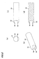
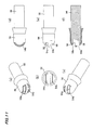
- FIG. 1 is a half section showing an applicator implement according to the embodiment of the invention.
- FIGS. 2 to 18 illustrate examples of individual parts. Parts allotted with the same reference numerals show identical components.
- the applicator implement is able to apply an application liquid by bringing an applying part 52 of an applicator body 50 impregnated with the application liquid into contact with a target object.
- the applicator implement includes applicator body 50 having a flat applying surface 58 (see FIG. 2 ) in applying part 52, and an applicator cover 56 that is fitted on the applicator body 50 to cover the applying part 52 and formed with a slit 54 for creating communication between the outside and the inside.
- applying surface 58 of the applying part 52 is positioned inside the slit 54.
- the applicator implement is constructed such that an approximately cylindrical outer barrel 10 with an open rear end 10b has a tank-like inner barrel 12 arranged movably forward and backward within outer barrel 10, inner barrel 12 moves forward relative to outer barrel 10 as the user clicks a rear end part 12b of inner barrel 12 so as to operate an aftermentioned valve mechanism 14 arranged inside front end part 12a of inner barrel 12, thereby supply the application liquid to applicator body 50 arranged at a front end part 10a of outer barrel 10.
- the part projected forward from front barrel 22 in applicator body 50 is covered with an aftermentioned applicator cover 56.
- Front end part 10a of outer barrel 10 is made small stepwise in diameter. Abutted on the front face of the front end part 10a is the outer periphery (spreading flange-like) of bowl-shaped front end part 18a of an ink feed pipe (a pipe passage for flowing the application liquid from valve mechanism 14 to the applicator body 50 side) 18. The rear part of applicator body 50 is inserted into front end part 18a of the ink feed pipe 18 with a seal ring 20 therebetween.
- Hollow-tubular tapering front barrel 22 is fitted on the outer barrel front end part 10a, enclosing by the hollow of front barrel 22, the applicator body 50 from its middle part to the rear, seal ring 20 and the front end part 18a of ink feed pipe 18, so as to fix applicator body 50, seal ring 20 and the front end part of ink feed pipe 18 to outer barrel 10.
- a cap 24 that encloses and protects applicator body 50 is removably fitted on outer barrel front end part 10a.
- Cap 24 has an inner cap 24 therein, which is urged by a spring 24b so as to press front barrel 22.
- the inner barrel 12 is closed at rear end 12b to form a liquid reserving space 12c for reserving the application liquid therein (in which an agitator ball 12d may be held).
- the valve mechanism 14 is mounted in front end part (the front end part of the inner barrel) 12a and fixed inside by inner front barrel 26.
- rear end part 18b of ink feed pipe 18 is slidably connected to valve mechanism 14 while inner front barrel 26 is fixed to front end part 12a of the inner barrel by screw-fitting or any other means with a packing 28 inserted between itself and the front end part of valve mechanism 14.
- valve mechanism 14 allows and stops supply of the application liquid toward applicator body 50 when a valve seat 30 and valve rod 38 relatively move in the axial direction, on the communication path between the liquid reserving space 12c for reserving the application liquid and applicator body 50.
- Valve seat body 30 of valve mechanism 14 is an approximate cylinder that is open at both ends in the axial direction and has liquid-tight portions that are formed therein on the front side (front side valve member 32) and on the rear side (rear side valve member 34) and come in sliding contact with valve rod. 38.
- the rear side opening faces liquid reserving space 12c while the front side opening faces the applicator body 50 side.
- valve rod 38 Projected radially inward from the interior wall of rear side valve member 34 of valve seat body 30 is a rib that extends from the approximate longitudinal center of the wall to the rear side to guide valve rod 38.
- the valve rod 38 is accommodated in the hollow of front side valve member 32 and rear side valve member 34 of valve seat body 30 so as to be movable forward and rearward.
- a spring member 36 that is fit on the valve rod 38 is disposed inside the same hollow so as to urge the valve rod 38 forward.
- front valve member 32 overall has an approximately cylindrical shape with a large-diametric flange at the front end and the rear side interior peripheral surface greater in diameter than the front interior peripheral surface. This rear side interior peripheral surface forms the front side liquid-tight portion.
- rear side valve member 34 has a hollowed, approximately cylindrical shape with large-diametric flange at the front end and the rear end reduced stepwise in diameter. The interior peripheral surface of this reduced-diametric portion forms the rear side liquid-tight portion.
- the front side valve member 32 is concentrically inserted overlappedly into rear side valve member 34 from the front side until the aforementioned flanges abut each other.
- inner front barrel 26 is screwed and fixed to cover front end part 12a of the inner barrel.
- the front face of the reduced-diametric portion at the rear side end of rear side valve member 34 serves as a seat for the spring member 36.
- valve rod 38 Formed on the outer periphery of valve rod 38 are a front side piston part 38a that liquid-tightly slides on the front side liquid-tight portion of front side valve member 32 in the valve seat body 30, and a rear side piston part 38b that liquid-tightly slides on the rear side liquid-tight portion of rear side valve member 34 in the valve seat body 30 while a space 40 that allows communication of the application liquid is formed between the outer periphery in the approximately center of the valve rod 38 and the interior surface of the valve seat body 30.
- front side piston part 38a of valve rod 38 is formed with a flexible large-diametric umbrella-like flange.
- Rear side piston part 38b is formed with a smooth outer peripheral surface tapering rearwards.
- An annular projection 42 is formed on the inner wall of outer barrel 10. When inner barrel 12 moves rearwards by a certain distance or greater, inner front barrel 26 abuts this annular projection 42 so as to prevent inner barrel 12 from moving to the rear further and coming off.
- ink feed pipe 18 communicating with applicator body 50 is inserted into the front side opening of valve seat body 30. Inserted into this ink feed pipe 18 is an induction rod 44 for inducing the application liquid toward applicator body 50.
- applicator body 50 may use a fabric body of acryl, nylon, polyester, polyacetal (POM) or the like.
- the inner barrel and output barrel 10 may use polypropylene (PP), polybutylene naphthalate (PBT), nylon (PA) and polyacrylonitrile (PAN); front barrel 22, cap 24, inner cap 24a and inner front barrel 26 may use polybutyl-terephthalate (PBT), polypropylene (PP), nylon (PA) and polyacrylonitrile (PAN); packing 28 may use EPDM, silicone, NBR (nitrile rubber), IIR (polyisobutylene rubber) and fluorine; the seal ring may use low-density polyethylene (LDPE, LLDPE), high-density polyethylene (HDPE), polypropylene (PP); front side valve member 32, rear side valve member 34 and valve rod 38 of valve seat body 30 may use high-density polyethylene (HDPE), low-density polyethylene (LDPE, LLDPE), polypropylene (PP); and, spring 24b of cap 24 and spring member 36 may use stainless steel (SUS).
- PP polypropylene
- PBT poly
- Induction rod 44 is preferably formed of a material presenting good wettability to the application liquid, for examples including, metals such as stainless steel (SUS), resin such as polyacetal (POM), fiber bundle core or sintered compact of polyester, acryl or the like, or synthesized resin molding core having liquid flow channels in the axial direction such as polyacetal (POM).
- metals such as stainless steel (SUS)
- resin such as polyacetal (POM)
- synthesized resin molding core having liquid flow channels in the axial direction such as polyacetal (POM).
- the applicator implement is preferably used for French nails, or applying the application liquid to nails tips.
- the application liquid for French nails should have a viscosity that enables applicator body 50 made of fibers to absorb/apply and apply the liquid on nails. It is preferably that the viscosity falls within a range from 50 mpa ⁇ s to 200 mpa ⁇ s.
- the material of applicator cover 5 6 may be high-polymer plastics such as polypropylene (PP), polyethylene (PE), polybutyl-telephthalate (PBT), polyacetal (POM), and nylon (PA), or metals, and preferably presents chemical resistance against the organic solvent liquids used for French nails.
- PP polypropylene
- PE polyethylene
- PBT polybutyl-telephthalate
- POM polyacetal
- PA nylon
- FIG. 2 shows applicator body 50 according to example 1.
- the applicator implement used in example 1 has the same outside diameter with that of applicator body 50 of the applicator implement of FIG. 1 .
- applicator body 50 roughly has a bar-shaped configuration with its applying part 52 at the front end cut out in a U-shape when viewed from side.
- opposing applying surfaces 58 are formed in the U-shaped arrangement.
- the U-shaped arrangement was formed of 1. 5 mm deep and 1. 5 mm wide. Accordingly, the insert limit of the nail is 1.5 mm, and it is possible to paint nails having the maximum thickness of 1.5 mm.
- This fabric body was assembled in the applicator implement of FIG. 1 , and application performance was evaluated.
- the nail was put into the fabric body up to the insert limit, and the nail was fixed at the point of the insert limit of the fabric body.
- the nail was painted by sliding the fabric body along the top edge of the nail. As a result, it was possible to draw a line of 1.5 mm wide easily and beautifully.
- Example 2 relates to an applicator cover.
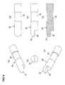
- FIG. 3 is a component drawing of an applicator cover.
- FIG. 4 is a component drawing of applicator body 50.
- FIG. 5 is an assembly diagram of applicator cover 56 and applicator body 50.
- applicator cover 56 forms a cap-like configuration in which the front end is spherically shape while the rear part become slightly spread like a skirt.
- Applicator cover 56 is formed in its front end with a window-forming slit 54 that is rectangularly cut out.
- One endface of slit 54 is continuously extended like a tread forming a step 54a inside applicator cover 56.
- the other endface of slit 54 is extended spherically both on the inner and outer surfaces.
- the slit 54 is 1.5 mm wide with the nail insert limit set at 1.8 mm.
- the outside diameter of applicator cover 56 is 5.3 mm.
- the cover has a key-like inner hollow similar to the shape of the applicator body and establishes communication.
- applicator body 50 of example 2 is formed such that, as shown in FIG. 4 , the one side of the front end part of applying part 52 is cut out like a notch to form a flat applying surface 58 extending in the axial direction of the applicator body 50.
- Applicator body 50 has an outside diameter of 4.5mm with its front end spherically shaped which is to become applying part 52, and is ground in flat along the axial direction, forming applying surface 58.
- the middle part is annularly cut out to be reduced to 4 mm in diameter, forming a depressed portion 60.
- the fabric body having a porosity of 50% or more was used as applicator body 50.
- applicator body 50 As applicator body 50 is fitted into applicator cover 56, applying surface 58 is exposed 0.5 mm relative to slit 54 as shown in FIG. 5 . Accordingly, it is possible to insert a nail without difficulty if the nail is as thick as about 1 mm.
- Applicator body 50 is positioned by the spherical part of applicator cover 56 or by step 54a of applicator cover 56. With the thus constructed applying part 52, the nail was inserted into slit 54 and fixed at the insert limit while the applicator implement was moved right and left along the top edge of the nail, whereby it was possible to draw a painting line of uniform width easily and beautifully.
- Variational example 1 of example 2 gives a configuration in which applicator cover 56 shown in FIG. 6 is formed with a slit 54 that is wider (deeper in side view) than that shown in FIG. 3 . Replacement of the applicator cover 56 shown in FIG. 3 with this configuration provides the assembly shown in FIG. 7 so that it is possible to change the application width of slit 54.
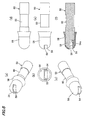
- FIG. 8 is an illustrative diagram of applicator cover 56 of example 3.
- FIG. 9 is an assembly diagram of applicator cover 56 and applicator body 50 of example 3.
- the applicator body 50 of example 3 is the same as that of example 2 shown in FIG. 4 .
- This example 3 is a further improved version of the assembly of example 2.
- Another hole 56a is formed in the top of applicator cover 56, separately from slit 54, so that the outer peripheral surface of applying part 52 is exposed from the hole 56a.
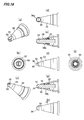
- FIG. 10 is a component drawing of applicator cover 56 according to example 4, and FIG. 11 is an illustrative diagram of the assembly.
- the applicator body 50 shown in FIG. 2 is used, and the applicator cover 56 shown in FIG. 11 and the applicator body 50 are assembled.
- two slits 54a and 54b different in depth (and width) are formed in applicator cover 56, and applicator body 50 is inserted into this applicator cover 56.
- applying surfaces 58, 58 opposing each other are made to face (exposed) through slits 54a and 54b, respectively.
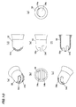
- FIG. 12 is a component drawing of an applicator body of example 5
- FIG. 13 is an illustrative diagram of the assembly of example 5.
- the applicator cover 56 of example 4 shown in FIG. 10 is assembled with applicator body of FIG. 12 , forming the assembly shown in FIG. 13 .
- applicator body 50 is different from example 4, in that applying part 52 as the front end of applicator body 50 is cut out from both side across the axis to form an inverted T shape and applying surfaces 58, 58 are formed on both the sides of inverted T-shaped applying part 52.
- applying surfaces 58 and 58 are exposed through slits 54a and 54b, respectively.
- FIG. 14 shows applicator cover 56 of variational example 2 of example 2
- FIG. 15 shows applicator cover 56 with applicator body 50 inserted therein.
- This variational example 2 gives a configuration in which, as shown in FIG. 14 , the skirt-like portion that is formed continuously or integrally from the rear part of applicator cover 56 is further extended so that applicator cover 56 is integrated with front barrel 22.
- applicator body 50 the one shown in FIG. 4 having applying part 52 cut out like a notch on one side forming applying surface 58 is used.
- FIGS. 14 and 15 the part of applicator cover 56 corresponding to the front barrel is shown by reference numeral 22A.
- This variational example 2 when used for the applicator implement shown in the embodiment of FIG. 1 , has the advantage of reducing the number of parts for front barrel 22 compared to the above examples 1 to 5.
- FIG. 16 is a partial assembly diagram of an applicator body (fabric body) according to example 6 inserted in applicator cover 56 and attached to front barrel 22.
- FIG. 17 is a partial assembly diagram of the applicator body (fabric body) inserted in the applicator cover before being attached to the front barrel 22.
- FIG. 18 is a component drawing of the applicator cover.
- Example 6 is a further improved version of example 3 described with FIGS. 8 and 9 above, in that the rear part of applicator cover 56 is extended tube-like (shown by a tubular portion 56b) compared to the configuration of example 3.
- applicator cover 56 is assembled so that applicator body 50 and tubular portion 56b in the rear part of applicator cover 56 are inserted into front barrel 22.
- the umbrella-like spreading portion in the front part of applicator cover 56 abuts the front end of front barrel 22 while tubular portion 56b is plunged into front barrel 22.
- Applicator body 50 is pressed by front barrel 22 through tubular portion 56b of applicator cover 56.
- applying part 52 in the conical side surface of applicator body 50 is exposed through the top hole 56a while flat applying surface 58 is exposed from slit 54.
- applicator implements including applicator body 50 and applicator cover 56 of the above examples 1 to 6, variational examples 1 and 2, in the applicator implement using applicator body 50 that can absorb and apply a liquid to paint the tips of nails by dispensing a content liquid in liquid reserving space 12c of inner barrel 12 to applicator body 50 by means of valve mechanism 14 that supplies the content liquid as rear end part 12b of inner barrel 12 is clicked, when the portion for painting nail tips is formed in a U-shape, a nail inserted into slit 54 up to the insert limit of the U-shape can be positioned and fixed, whereby it is possible to provide an applying part for nail art that enables easy application of the liquid dispensed from the container to applicator body 50, to the nail, by moving applying part 52 left and right along the top edge of the nail.
- the applicator body 50 maybe formed with a curved surface. It is also possible to omit applicator cover 56 if application can be done with applicator body 50 alone. Omission of applicator cover 56 enables easy application with a simple configuration.
- the applicator implement of the present invention is not only suitable for French nails, or painting around nail tips in association with making up of fingertips of the hands, but can also be used when lines of uniform width need to be drawn on a tip of a small object like nail tips.
Landscapes
- Coating Apparatus (AREA)
- Pens And Brushes (AREA)
Applications Claiming Priority (3)
| Application Number | Priority Date | Filing Date | Title |
|---|---|---|---|
| JP2012004760 | 2012-01-13 | ||
| JP2013003512A JP6145272B2 (ja) | 2012-01-13 | 2013-01-11 | 塗布具 |
| PCT/JP2013/050572 WO2013105669A1 (ja) | 2012-01-13 | 2013-01-15 | 塗布具 |
Publications (3)
| Publication Number | Publication Date |
|---|---|
| EP2803291A1 true EP2803291A1 (de) | 2014-11-19 |
| EP2803291A4 EP2803291A4 (de) | 2015-07-22 |
| EP2803291B1 EP2803291B1 (de) | 2017-03-08 |
Family
ID=48781609
Family Applications (1)
| Application Number | Title | Priority Date | Filing Date |
|---|---|---|---|
| EP13736173.9A Not-in-force EP2803291B1 (de) | 2012-01-13 | 2013-01-15 | Applikatorvorrichtung |
Country Status (4)
| Country | Link |
|---|---|
| US (1) | US20140360525A1 (de) |
| EP (1) | EP2803291B1 (de) |
| JP (1) | JP6145272B2 (de) |
| WO (1) | WO2013105669A1 (de) |
Cited By (2)
| Publication number | Priority date | Publication date | Assignee | Title |
|---|---|---|---|---|
| GB2534275A (en) * | 2014-11-15 | 2016-07-20 | Moore Amy | A device for fluid application |
| US20170252624A1 (en) * | 2016-03-07 | 2017-09-07 | Pe Redskaber A/S | Gymnastics Gear |
Families Citing this family (6)
| Publication number | Priority date | Publication date | Assignee | Title |
|---|---|---|---|---|
| US10306969B1 (en) * | 2015-11-25 | 2019-06-04 | Noushin Laaly | Nail pen nib |
| WO2019083325A1 (ko) * | 2017-10-26 | 2019-05-02 | (주)아우딘퓨쳐스 | 아이라이너 |
| KR102000783B1 (ko) * | 2017-10-26 | 2019-07-16 | (주)아우딘퓨쳐스 | 아이라이너 |
| CN110754770A (zh) * | 2019-10-29 | 2020-02-07 | 上海魅奈儿科技有限公司 | 一种美甲方法及美甲机 |
| JP2021132833A (ja) * | 2020-02-26 | 2021-09-13 | Wit株式会社 | 塗布具 |
| JP7813448B2 (ja) * | 2020-11-05 | 2026-02-13 | Wit株式会社 | 塗布具 |
Family Cites Families (23)
| Publication number | Priority date | Publication date | Assignee | Title |
|---|---|---|---|---|
| US2117053A (en) * | 1937-02-23 | 1938-05-10 | Bickley Elmer | Fingernail file |
| US2399463A (en) * | 1943-12-02 | 1946-04-30 | Frederick W Bryant | Holder and applicator for cosmetic liquids and the like |
| US2568328A (en) * | 1948-08-06 | 1951-09-18 | Elby Joseph | Nail polish applicator |
| US3146806A (en) * | 1962-08-09 | 1964-09-01 | Ginsburg Henry | Dispensing container for liquids |
| US4712571A (en) * | 1984-06-29 | 1987-12-15 | Chesebrough-Pond's, Inc. | Nail polish compositions and means for applying same |
| GB2191396A (en) * | 1986-06-10 | 1987-12-16 | Lamberto De Santis | A portable powered device for the care of finger nails |
| US4747419A (en) * | 1986-06-17 | 1988-05-31 | Chesebrough-Pond's, Inc. | Nail polish compositions and means for applying same |
| US4944318A (en) * | 1988-11-07 | 1990-07-31 | Gaylord Jr Thurmond O | Nail polish applicator |
| US5161552A (en) * | 1991-10-28 | 1992-11-10 | Kathuria Mineshwar K | Nail filer |
| US6209548B1 (en) * | 1999-03-08 | 2001-04-03 | Beauty Innovations | Method and apparatus for nail coloring |
| FR2825592B1 (fr) * | 2001-06-08 | 2003-08-08 | Oreal | Dispositif pour l'application en meches d'un produit capillaire, et procede de traitement capillaire |
| JP3927034B2 (ja) * | 2002-01-07 | 2007-06-06 | 株式会社呉竹 | 筆穂カバー部材及び筆具 |
| FR2836029B1 (fr) * | 2002-02-21 | 2004-05-07 | Oreal | Dispositif pour appliquer un produit sur les ongles |
| JP2004059035A (ja) | 2002-07-26 | 2004-02-26 | Mitsubishi Pencil Co Ltd | 液体塗布容器 |
| JP3978167B2 (ja) | 2003-10-16 | 2007-09-19 | 株式会社ディーエイチシー | フレンチネイル用ブラシ付きネイルアート容器 |
| JP2006204332A (ja) * | 2005-01-25 | 2006-08-10 | Aubex Corp | ネイルアート用塗布具 |
| JP2006296620A (ja) | 2005-04-19 | 2006-11-02 | Mika Takagi | フレンチネイル用粘着シール |
| FR2903869B1 (fr) * | 2006-07-19 | 2009-01-09 | Oreal | Dispositif et procede pour appliquer un produit sur un ongle ensemble de stockage et d'application d'un tel produit |
| CN101896364B (zh) * | 2007-12-12 | 2012-01-25 | 三菱铅笔株式会社 | 涂布器 |
| US20100083976A1 (en) * | 2008-10-06 | 2010-04-08 | Maryann Montana-Selers | Method and apparatus for completing a French manicure |
| FR2939620B1 (fr) * | 2008-12-17 | 2011-05-20 | Oreal | Procede de revetement de l'extremite des ongles. |
| FR2948266B1 (fr) * | 2009-07-22 | 2011-08-26 | Oreal | Applicateur de vernis a ongles de type french manucure |
| WO2012050632A1 (en) * | 2010-10-15 | 2012-04-19 | Laaly Noushin A | Apparatus and device for distal-nail-portion varnish application |
-
2013
- 2013-01-11 JP JP2013003512A patent/JP6145272B2/ja active Active
- 2013-01-15 WO PCT/JP2013/050572 patent/WO2013105669A1/ja not_active Ceased
- 2013-01-15 EP EP13736173.9A patent/EP2803291B1/de not_active Not-in-force
- 2013-01-15 US US14/371,879 patent/US20140360525A1/en not_active Abandoned
Cited By (2)
| Publication number | Priority date | Publication date | Assignee | Title |
|---|---|---|---|---|
| GB2534275A (en) * | 2014-11-15 | 2016-07-20 | Moore Amy | A device for fluid application |
| US20170252624A1 (en) * | 2016-03-07 | 2017-09-07 | Pe Redskaber A/S | Gymnastics Gear |
Also Published As
| Publication number | Publication date |
|---|---|
| JP2013163016A (ja) | 2013-08-22 |
| US20140360525A1 (en) | 2014-12-11 |
| EP2803291A4 (de) | 2015-07-22 |
| WO2013105669A1 (ja) | 2013-07-18 |
| JP6145272B2 (ja) | 2017-06-07 |
| EP2803291B1 (de) | 2017-03-08 |
Similar Documents
| Publication | Publication Date | Title |
|---|---|---|
| EP2803291B1 (de) | Applikatorvorrichtung | |
| EP2319358B1 (de) | Werkzeug zur aufbringung von flüssigkeiten | |
| KR101833957B1 (ko) | 화장품 디스펜서 | |
| US11540613B2 (en) | Nail pen nib | |
| US7461988B2 (en) | Packaging and applicator device for applying a substance | |
| US9908362B2 (en) | Liquid applying container | |
| EP2223811A1 (de) | Applikator | |
| US20190001368A1 (en) | Device for applying adhesive and/or Sealant | |
| US7972075B2 (en) | Applicator | |
| JP2017538560A (ja) | 美容用またはケア用の製品を塗布するためのアプリケータ | |
| JP6159590B2 (ja) | マッサージ機能付き液体塗布具 | |
| US8905666B2 (en) | Liquid applicator | |
| TWI576066B (zh) | Applying applicator and container for double eyelid formation solution | |
| US9073200B2 (en) | Pliant removeable airbrush grip | |
| CA2742738C (en) | An apparatus for applying a fluid substance | |
| KR930003162Y1 (ko) | 유동체 도포구 | |
| EP4115766B1 (de) | Vorrichtung zum schminken der augenkontur | |
| TWM538348U (zh) | 直液式雙頭化妝筆 | |
| RU2778609C1 (ru) | Картридж для нанесения татуировок | |
| TWM534549U (zh) | 可轉動眉筆的雙頭式化妝筆 | |
| JP6424019B2 (ja) | 液体塗布具 | |
| US20170079406A1 (en) | Cosmetic product applicator with a felt tip | |
| JP5328323B2 (ja) | 塗布具 | |
| JP2026005085A (ja) | ブラシ型塗布具 | |
| KR101673149B1 (ko) | 아이라이너 |
Legal Events
| Date | Code | Title | Description |
|---|---|---|---|
| PUAI | Public reference made under article 153(3) epc to a published international application that has entered the european phase |
Free format text: ORIGINAL CODE: 0009012 |
|
| 17P | Request for examination filed |
Effective date: 20140717 |
|
| AK | Designated contracting states |
Kind code of ref document: A1 Designated state(s): AL AT BE BG CH CY CZ DE DK EE ES FI FR GB GR HR HU IE IS IT LI LT LU LV MC MK MT NL NO PL PT RO RS SE SI SK SM TR |
|
| DAX | Request for extension of the european patent (deleted) | ||
| RA4 | Supplementary search report drawn up and despatched (corrected) |
Effective date: 20150619 |
|
| RIC1 | Information provided on ipc code assigned before grant |
Ipc: A45D 34/04 20060101ALI20150615BHEP Ipc: A45D 29/00 20060101AFI20150615BHEP |
|
| RAP1 | Party data changed (applicant data changed or rights of an application transferred) |
Owner name: MITSUBISHI PENCIL COMPANY, LIMITED |
|
| RIN1 | Information on inventor provided before grant (corrected) |
Inventor name: UEHARA, JUNYA |
|
| GRAP | Despatch of communication of intention to grant a patent |
Free format text: ORIGINAL CODE: EPIDOSNIGR1 |
|
| INTG | Intention to grant announced |
Effective date: 20160811 |
|
| GRAS | Grant fee paid |
Free format text: ORIGINAL CODE: EPIDOSNIGR3 |
|
| STAA | Information on the status of an ep patent application or granted ep patent |
Free format text: STATUS: GRANT OF PATENT IS INTENDED |
|
| GRAA | (expected) grant |
Free format text: ORIGINAL CODE: 0009210 |
|
| STAA | Information on the status of an ep patent application or granted ep patent |
Free format text: STATUS: THE PATENT HAS BEEN GRANTED |
|
| AK | Designated contracting states |
Kind code of ref document: B1 Designated state(s): AL AT BE BG CH CY CZ DE DK EE ES FI FR GB GR HR HU IE IS IT LI LT LU LV MC MK MT NL NO PL PT RO RS SE SI SK SM TR |
|
| REG | Reference to a national code |
Ref country code: GB Ref legal event code: FG4D |
|
| REG | Reference to a national code |
Ref country code: CH Ref legal event code: EP Ref country code: AT Ref legal event code: REF Ref document number: 872734 Country of ref document: AT Kind code of ref document: T Effective date: 20170315 |
|
| REG | Reference to a national code |
Ref country code: IE Ref legal event code: FG4D |
|
| REG | Reference to a national code |
Ref country code: DE Ref legal event code: R096 Ref document number: 602013018295 Country of ref document: DE |
|
| REG | Reference to a national code |
Ref country code: LT Ref legal event code: MG4D |
|
| REG | Reference to a national code |
Ref country code: NL Ref legal event code: MP Effective date: 20170308 |
|
| PG25 | Lapsed in a contracting state [announced via postgrant information from national office to epo] |
Ref country code: LT Free format text: LAPSE BECAUSE OF FAILURE TO SUBMIT A TRANSLATION OF THE DESCRIPTION OR TO PAY THE FEE WITHIN THE PRESCRIBED TIME-LIMIT Effective date: 20170308 Ref country code: HR Free format text: LAPSE BECAUSE OF FAILURE TO SUBMIT A TRANSLATION OF THE DESCRIPTION OR TO PAY THE FEE WITHIN THE PRESCRIBED TIME-LIMIT Effective date: 20170308 Ref country code: NO Free format text: LAPSE BECAUSE OF FAILURE TO SUBMIT A TRANSLATION OF THE DESCRIPTION OR TO PAY THE FEE WITHIN THE PRESCRIBED TIME-LIMIT Effective date: 20170608 Ref country code: GR Free format text: LAPSE BECAUSE OF FAILURE TO SUBMIT A TRANSLATION OF THE DESCRIPTION OR TO PAY THE FEE WITHIN THE PRESCRIBED TIME-LIMIT Effective date: 20170609 Ref country code: FI Free format text: LAPSE BECAUSE OF FAILURE TO SUBMIT A TRANSLATION OF THE DESCRIPTION OR TO PAY THE FEE WITHIN THE PRESCRIBED TIME-LIMIT Effective date: 20170308 |
|
| REG | Reference to a national code |
Ref country code: AT Ref legal event code: MK05 Ref document number: 872734 Country of ref document: AT Kind code of ref document: T Effective date: 20170308 |
|
| PG25 | Lapsed in a contracting state [announced via postgrant information from national office to epo] |
Ref country code: LV Free format text: LAPSE BECAUSE OF FAILURE TO SUBMIT A TRANSLATION OF THE DESCRIPTION OR TO PAY THE FEE WITHIN THE PRESCRIBED TIME-LIMIT Effective date: 20170308 Ref country code: ES Free format text: LAPSE BECAUSE OF FAILURE TO SUBMIT A TRANSLATION OF THE DESCRIPTION OR TO PAY THE FEE WITHIN THE PRESCRIBED TIME-LIMIT Effective date: 20170308 Ref country code: RS Free format text: LAPSE BECAUSE OF FAILURE TO SUBMIT A TRANSLATION OF THE DESCRIPTION OR TO PAY THE FEE WITHIN THE PRESCRIBED TIME-LIMIT Effective date: 20170308 Ref country code: SE Free format text: LAPSE BECAUSE OF FAILURE TO SUBMIT A TRANSLATION OF THE DESCRIPTION OR TO PAY THE FEE WITHIN THE PRESCRIBED TIME-LIMIT Effective date: 20170308 Ref country code: BG Free format text: LAPSE BECAUSE OF FAILURE TO SUBMIT A TRANSLATION OF THE DESCRIPTION OR TO PAY THE FEE WITHIN THE PRESCRIBED TIME-LIMIT Effective date: 20170608 |
|
| PG25 | Lapsed in a contracting state [announced via postgrant information from national office to epo] |
Ref country code: NL Free format text: LAPSE BECAUSE OF FAILURE TO SUBMIT A TRANSLATION OF THE DESCRIPTION OR TO PAY THE FEE WITHIN THE PRESCRIBED TIME-LIMIT Effective date: 20170308 |
|
| PG25 | Lapsed in a contracting state [announced via postgrant information from national office to epo] |
Ref country code: SK Free format text: LAPSE BECAUSE OF FAILURE TO SUBMIT A TRANSLATION OF THE DESCRIPTION OR TO PAY THE FEE WITHIN THE PRESCRIBED TIME-LIMIT Effective date: 20170308 Ref country code: RO Free format text: LAPSE BECAUSE OF FAILURE TO SUBMIT A TRANSLATION OF THE DESCRIPTION OR TO PAY THE FEE WITHIN THE PRESCRIBED TIME-LIMIT Effective date: 20170308 Ref country code: EE Free format text: LAPSE BECAUSE OF FAILURE TO SUBMIT A TRANSLATION OF THE DESCRIPTION OR TO PAY THE FEE WITHIN THE PRESCRIBED TIME-LIMIT Effective date: 20170308 Ref country code: AT Free format text: LAPSE BECAUSE OF FAILURE TO SUBMIT A TRANSLATION OF THE DESCRIPTION OR TO PAY THE FEE WITHIN THE PRESCRIBED TIME-LIMIT Effective date: 20170308 Ref country code: CZ Free format text: LAPSE BECAUSE OF FAILURE TO SUBMIT A TRANSLATION OF THE DESCRIPTION OR TO PAY THE FEE WITHIN THE PRESCRIBED TIME-LIMIT Effective date: 20170308 |
|
| PG25 | Lapsed in a contracting state [announced via postgrant information from national office to epo] |
Ref country code: IS Free format text: LAPSE BECAUSE OF FAILURE TO SUBMIT A TRANSLATION OF THE DESCRIPTION OR TO PAY THE FEE WITHIN THE PRESCRIBED TIME-LIMIT Effective date: 20170708 Ref country code: PL Free format text: LAPSE BECAUSE OF FAILURE TO SUBMIT A TRANSLATION OF THE DESCRIPTION OR TO PAY THE FEE WITHIN THE PRESCRIBED TIME-LIMIT Effective date: 20170308 Ref country code: SM Free format text: LAPSE BECAUSE OF FAILURE TO SUBMIT A TRANSLATION OF THE DESCRIPTION OR TO PAY THE FEE WITHIN THE PRESCRIBED TIME-LIMIT Effective date: 20170308 Ref country code: PT Free format text: LAPSE BECAUSE OF FAILURE TO SUBMIT A TRANSLATION OF THE DESCRIPTION OR TO PAY THE FEE WITHIN THE PRESCRIBED TIME-LIMIT Effective date: 20170710 |
|
| REG | Reference to a national code |
Ref country code: FR Ref legal event code: PLFP Year of fee payment: 6 Ref country code: DE Ref legal event code: R097 Ref document number: 602013018295 Country of ref document: DE |
|
| PLBE | No opposition filed within time limit |
Free format text: ORIGINAL CODE: 0009261 |
|
| STAA | Information on the status of an ep patent application or granted ep patent |
Free format text: STATUS: NO OPPOSITION FILED WITHIN TIME LIMIT |
|
| PG25 | Lapsed in a contracting state [announced via postgrant information from national office to epo] |
Ref country code: DK Free format text: LAPSE BECAUSE OF FAILURE TO SUBMIT A TRANSLATION OF THE DESCRIPTION OR TO PAY THE FEE WITHIN THE PRESCRIBED TIME-LIMIT Effective date: 20170308 |
|
| 26N | No opposition filed |
Effective date: 20171211 |
|
| PG25 | Lapsed in a contracting state [announced via postgrant information from national office to epo] |
Ref country code: IT Free format text: LAPSE BECAUSE OF FAILURE TO SUBMIT A TRANSLATION OF THE DESCRIPTION OR TO PAY THE FEE WITHIN THE PRESCRIBED TIME-LIMIT Effective date: 20170308 Ref country code: SI Free format text: LAPSE BECAUSE OF FAILURE TO SUBMIT A TRANSLATION OF THE DESCRIPTION OR TO PAY THE FEE WITHIN THE PRESCRIBED TIME-LIMIT Effective date: 20170308 |
|
| REG | Reference to a national code |
Ref country code: DE Ref legal event code: R119 Ref document number: 602013018295 Country of ref document: DE |
|
| REG | Reference to a national code |
Ref country code: CH Ref legal event code: PL |
|
| GBPC | Gb: european patent ceased through non-payment of renewal fee |
Effective date: 20180115 |
|
| PG25 | Lapsed in a contracting state [announced via postgrant information from national office to epo] |
Ref country code: LU Free format text: LAPSE BECAUSE OF NON-PAYMENT OF DUE FEES Effective date: 20180115 Ref country code: DE Free format text: LAPSE BECAUSE OF NON-PAYMENT OF DUE FEES Effective date: 20180801 |
|
| REG | Reference to a national code |
Ref country code: IE Ref legal event code: MM4A |
|
| REG | Reference to a national code |
Ref country code: BE Ref legal event code: MM Effective date: 20180131 |
|
| PG25 | Lapsed in a contracting state [announced via postgrant information from national office to epo] |
Ref country code: LI Free format text: LAPSE BECAUSE OF NON-PAYMENT OF DUE FEES Effective date: 20180131 Ref country code: GB Free format text: LAPSE BECAUSE OF NON-PAYMENT OF DUE FEES Effective date: 20180115 Ref country code: BE Free format text: LAPSE BECAUSE OF NON-PAYMENT OF DUE FEES Effective date: 20180131 Ref country code: CH Free format text: LAPSE BECAUSE OF NON-PAYMENT OF DUE FEES Effective date: 20180131 |
|
| PG25 | Lapsed in a contracting state [announced via postgrant information from national office to epo] |
Ref country code: IE Free format text: LAPSE BECAUSE OF NON-PAYMENT OF DUE FEES Effective date: 20180115 |
|
| PG25 | Lapsed in a contracting state [announced via postgrant information from national office to epo] |
Ref country code: MC Free format text: LAPSE BECAUSE OF FAILURE TO SUBMIT A TRANSLATION OF THE DESCRIPTION OR TO PAY THE FEE WITHIN THE PRESCRIBED TIME-LIMIT Effective date: 20170308 |
|
| PG25 | Lapsed in a contracting state [announced via postgrant information from national office to epo] |
Ref country code: MT Free format text: LAPSE BECAUSE OF NON-PAYMENT OF DUE FEES Effective date: 20180115 |
|
| PG25 | Lapsed in a contracting state [announced via postgrant information from national office to epo] |
Ref country code: TR Free format text: LAPSE BECAUSE OF FAILURE TO SUBMIT A TRANSLATION OF THE DESCRIPTION OR TO PAY THE FEE WITHIN THE PRESCRIBED TIME-LIMIT Effective date: 20170308 |
|
| PG25 | Lapsed in a contracting state [announced via postgrant information from national office to epo] |
Ref country code: HU Free format text: LAPSE BECAUSE OF FAILURE TO SUBMIT A TRANSLATION OF THE DESCRIPTION OR TO PAY THE FEE WITHIN THE PRESCRIBED TIME-LIMIT; INVALID AB INITIO Effective date: 20130115 |
|
| PG25 | Lapsed in a contracting state [announced via postgrant information from national office to epo] |
Ref country code: CY Free format text: LAPSE BECAUSE OF FAILURE TO SUBMIT A TRANSLATION OF THE DESCRIPTION OR TO PAY THE FEE WITHIN THE PRESCRIBED TIME-LIMIT Effective date: 20170308 Ref country code: MK Free format text: LAPSE BECAUSE OF NON-PAYMENT OF DUE FEES Effective date: 20170308 |
|
| PG25 | Lapsed in a contracting state [announced via postgrant information from national office to epo] |
Ref country code: AL Free format text: LAPSE BECAUSE OF FAILURE TO SUBMIT A TRANSLATION OF THE DESCRIPTION OR TO PAY THE FEE WITHIN THE PRESCRIBED TIME-LIMIT Effective date: 20170308 |
|
| PGFP | Annual fee paid to national office [announced via postgrant information from national office to epo] |
Ref country code: FR Payment date: 20211217 Year of fee payment: 10 |
|
| PG25 | Lapsed in a contracting state [announced via postgrant information from national office to epo] |
Ref country code: FR Free format text: LAPSE BECAUSE OF NON-PAYMENT OF DUE FEES Effective date: 20230131 |