EP2802869B1 - Lame d'essai d'immunodosage - Google Patents
Lame d'essai d'immunodosage Download PDFInfo
- Publication number
- EP2802869B1 EP2802869B1 EP13736046.7A EP13736046A EP2802869B1 EP 2802869 B1 EP2802869 B1 EP 2802869B1 EP 13736046 A EP13736046 A EP 13736046A EP 2802869 B1 EP2802869 B1 EP 2802869B1
- Authority
- EP
- European Patent Office
- Prior art keywords
- housing
- slide
- immunoassay test
- test slide
- porous carrier
- Prior art date
- Legal status (The legal status is an assumption and is not a legal conclusion. Google has not performed a legal analysis and makes no representation as to the accuracy of the status listed.)
- Active
Links
- 238000003018 immunoassay Methods 0.000 title claims description 104
- 239000011159 matrix material Substances 0.000 claims description 92
- 239000003153 chemical reaction reagent Substances 0.000 claims description 80
- 239000012530 fluid Substances 0.000 claims description 57
- 239000000463 material Substances 0.000 claims description 48
- 238000012360 testing method Methods 0.000 claims description 43
- 239000012491 analyte Substances 0.000 claims description 38
- 239000007788 liquid Substances 0.000 claims description 17
- 239000004793 Polystyrene Substances 0.000 claims description 13
- 229920002223 polystyrene Polymers 0.000 claims description 13
- 229920003023 plastic Polymers 0.000 claims description 6
- 239000004033 plastic Substances 0.000 claims description 6
- 239000003365 glass fiber Substances 0.000 claims description 3
- 239000011230 binding agent Substances 0.000 claims description 2
- 238000004891 communication Methods 0.000 claims description 2
- 239000000523 sample Substances 0.000 description 75
- 239000000126 substance Substances 0.000 description 30
- -1 polypropylene Polymers 0.000 description 17
- 238000003556 assay Methods 0.000 description 14
- 238000005259 measurement Methods 0.000 description 13
- 239000004698 Polyethylene Substances 0.000 description 12
- 229920000573 polyethylene Polymers 0.000 description 11
- 239000000758 substrate Substances 0.000 description 11
- 239000002250 absorbent Substances 0.000 description 10
- 230000002745 absorbent Effects 0.000 description 10
- 230000009870 specific binding Effects 0.000 description 10
- 239000006226 wash reagent Substances 0.000 description 10
- 238000000034 method Methods 0.000 description 9
- 239000000243 solution Substances 0.000 description 9
- 230000027455 binding Effects 0.000 description 8
- 239000011148 porous material Substances 0.000 description 8
- 239000000203 mixture Substances 0.000 description 7
- 230000003287 optical effect Effects 0.000 description 7
- 210000002966 serum Anatomy 0.000 description 7
- 229920002799 BoPET Polymers 0.000 description 6
- 239000005041 Mylar™ Substances 0.000 description 6
- 230000007246 mechanism Effects 0.000 description 6
- 239000012528 membrane Substances 0.000 description 6
- 241000282324 Felis Species 0.000 description 5
- 210000004369 blood Anatomy 0.000 description 5
- 239000008280 blood Substances 0.000 description 5
- 238000001514 detection method Methods 0.000 description 5
- 239000003085 diluting agent Substances 0.000 description 5
- 238000003466 welding Methods 0.000 description 5
- 239000004677 Nylon Substances 0.000 description 4
- 239000000853 adhesive Substances 0.000 description 4
- 230000001070 adhesive effect Effects 0.000 description 4
- 239000000427 antigen Substances 0.000 description 4
- 102000036639 antigens Human genes 0.000 description 4
- 108091007433 antigens Proteins 0.000 description 4
- 229920002678 cellulose Polymers 0.000 description 4
- 239000001913 cellulose Substances 0.000 description 4
- 239000013078 crystal Substances 0.000 description 4
- 238000003780 insertion Methods 0.000 description 4
- 230000037431 insertion Effects 0.000 description 4
- 238000002156 mixing Methods 0.000 description 4
- 229920001778 nylon Polymers 0.000 description 4
- 230000007723 transport mechanism Effects 0.000 description 4
- OKKJLVBELUTLKV-UHFFFAOYSA-N Methanol Chemical compound OC OKKJLVBELUTLKV-UHFFFAOYSA-N 0.000 description 3
- 102000019280 Pancreatic lipases Human genes 0.000 description 3
- 108050006759 Pancreatic lipases Proteins 0.000 description 3
- 239000004699 Ultra-high molecular weight polyethylene Substances 0.000 description 3
- 230000004927 fusion Effects 0.000 description 3
- 239000011521 glass Substances 0.000 description 3
- 229940116369 pancreatic lipase Drugs 0.000 description 3
- 230000002093 peripheral effect Effects 0.000 description 3
- 239000007790 solid phase Substances 0.000 description 3
- 239000012780 transparent material Substances 0.000 description 3
- 229920000785 ultra high molecular weight polyethylene Polymers 0.000 description 3
- 239000011534 wash buffer Substances 0.000 description 3
- UAIUNKRWKOVEES-UHFFFAOYSA-N 3,3',5,5'-tetramethylbenzidine Chemical compound CC1=C(N)C(C)=CC(C=2C=C(C)C(N)=C(C)C=2)=C1 UAIUNKRWKOVEES-UHFFFAOYSA-N 0.000 description 2
- XUIIKFGFIJCVMT-GFCCVEGCSA-N D-thyroxine Chemical compound IC1=CC(C[C@@H](N)C(O)=O)=CC(I)=C1OC1=CC(I)=C(O)C(I)=C1 XUIIKFGFIJCVMT-GFCCVEGCSA-N 0.000 description 2
- 102000004190 Enzymes Human genes 0.000 description 2
- 108090000790 Enzymes Proteins 0.000 description 2
- 239000000020 Nitrocellulose Substances 0.000 description 2
- 102000003992 Peroxidases Human genes 0.000 description 2
- 239000004952 Polyamide Substances 0.000 description 2
- 229920002873 Polyethylenimine Polymers 0.000 description 2
- 239000004743 Polypropylene Substances 0.000 description 2
- VYPSYNLAJGMNEJ-UHFFFAOYSA-N Silicium dioxide Chemical compound O=[Si]=O VYPSYNLAJGMNEJ-UHFFFAOYSA-N 0.000 description 2
- PPBRXRYQALVLMV-UHFFFAOYSA-N Styrene Chemical compound C=CC1=CC=CC=C1 PPBRXRYQALVLMV-UHFFFAOYSA-N 0.000 description 2
- XTXRWKRVRITETP-UHFFFAOYSA-N Vinyl acetate Chemical compound CC(=O)OC=C XTXRWKRVRITETP-UHFFFAOYSA-N 0.000 description 2
- BZHJMEDXRYGGRV-UHFFFAOYSA-N Vinyl chloride Chemical compound ClC=C BZHJMEDXRYGGRV-UHFFFAOYSA-N 0.000 description 2
- 150000001336 alkenes Chemical class 0.000 description 2
- 238000002820 assay format Methods 0.000 description 2
- 239000011575 calcium Substances 0.000 description 2
- 239000007795 chemical reaction product Substances 0.000 description 2
- 229920001577 copolymer Polymers 0.000 description 2
- 238000011161 development Methods 0.000 description 2
- 201000010099 disease Diseases 0.000 description 2
- 208000037265 diseases, disorders, signs and symptoms Diseases 0.000 description 2
- 229940088598 enzyme Drugs 0.000 description 2
- 238000011534 incubation Methods 0.000 description 2
- 238000011068 loading method Methods 0.000 description 2
- 238000004519 manufacturing process Methods 0.000 description 2
- 230000013011 mating Effects 0.000 description 2
- 229920001220 nitrocellulos Polymers 0.000 description 2
- 230000009871 nonspecific binding Effects 0.000 description 2
- JRZJOMJEPLMPRA-UHFFFAOYSA-N olefin Natural products CCCCCCCC=C JRZJOMJEPLMPRA-UHFFFAOYSA-N 0.000 description 2
- 239000000123 paper Substances 0.000 description 2
- 239000002245 particle Substances 0.000 description 2
- 239000012466 permeate Substances 0.000 description 2
- 108040007629 peroxidase activity proteins Proteins 0.000 description 2
- 229920002647 polyamide Polymers 0.000 description 2
- 239000004417 polycarbonate Substances 0.000 description 2
- 229920000515 polycarbonate Polymers 0.000 description 2
- 229920001155 polypropylene Polymers 0.000 description 2
- 229920002689 polyvinyl acetate Polymers 0.000 description 2
- 239000011118 polyvinyl acetate Substances 0.000 description 2
- 239000004800 polyvinyl chloride Substances 0.000 description 2
- 229920000915 polyvinyl chloride Polymers 0.000 description 2
- 238000011002 quantification Methods 0.000 description 2
- 230000002441 reversible effect Effects 0.000 description 2
- 229920006395 saturated elastomer Polymers 0.000 description 2
- 238000009738 saturating Methods 0.000 description 2
- 239000004094 surface-active agent Substances 0.000 description 2
- 229920001169 thermoplastic Polymers 0.000 description 2
- 239000012815 thermoplastic material Substances 0.000 description 2
- 229920000936 Agarose Polymers 0.000 description 1
- OYPRJOBELJOOCE-UHFFFAOYSA-N Calcium Chemical compound [Ca] OYPRJOBELJOOCE-UHFFFAOYSA-N 0.000 description 1
- 229920000742 Cotton Polymers 0.000 description 1
- 229920002307 Dextran Polymers 0.000 description 1
- LFQSCWFLJHTTHZ-UHFFFAOYSA-N Ethanol Chemical compound CCO LFQSCWFLJHTTHZ-UHFFFAOYSA-N 0.000 description 1
- 241000714165 Feline leukemia virus Species 0.000 description 1
- 108010010803 Gelatin Proteins 0.000 description 1
- WQZGKKKJIJFFOK-GASJEMHNSA-N Glucose Natural products OC[C@H]1OC(O)[C@H](O)[C@@H](O)[C@@H]1O WQZGKKKJIJFFOK-GASJEMHNSA-N 0.000 description 1
- 102400001066 Growth hormone-binding protein Human genes 0.000 description 1
- 101800000194 Growth hormone-binding protein Proteins 0.000 description 1
- 108010001336 Horseradish Peroxidase Proteins 0.000 description 1
- 206010061598 Immunodeficiency Diseases 0.000 description 1
- 208000029462 Immunodeficiency disease Diseases 0.000 description 1
- CKLJMWTZIZZHCS-REOHCLBHSA-N L-aspartic acid Chemical compound OC(=O)[C@@H](N)CC(O)=O CKLJMWTZIZZHCS-REOHCLBHSA-N 0.000 description 1
- 229920002472 Starch Polymers 0.000 description 1
- 241000700605 Viruses Species 0.000 description 1
- 239000002253 acid Substances 0.000 description 1
- 229940009098 aspartate Drugs 0.000 description 1
- QVGXLLKOCUKJST-UHFFFAOYSA-N atomic oxygen Chemical compound [O] QVGXLLKOCUKJST-UHFFFAOYSA-N 0.000 description 1
- 239000011324 bead Substances 0.000 description 1
- 239000012472 biological sample Substances 0.000 description 1
- 230000015572 biosynthetic process Effects 0.000 description 1
- 229910052791 calcium Inorganic materials 0.000 description 1
- 229920002301 cellulose acetate Polymers 0.000 description 1
- 229910010293 ceramic material Inorganic materials 0.000 description 1
- 230000000295 complement effect Effects 0.000 description 1
- 150000001875 compounds Chemical class 0.000 description 1
- 238000011109 contamination Methods 0.000 description 1
- 238000007796 conventional method Methods 0.000 description 1
- 229920003020 cross-linked polyethylene Polymers 0.000 description 1
- 239000004703 cross-linked polyethylene Substances 0.000 description 1
- 238000000151 deposition Methods 0.000 description 1
- 239000010432 diamond Substances 0.000 description 1
- 238000001035 drying Methods 0.000 description 1
- 238000005516 engineering process Methods 0.000 description 1
- 239000004744 fabric Substances 0.000 description 1
- 239000000835 fiber Substances 0.000 description 1
- 239000011152 fibreglass Substances 0.000 description 1
- 239000010419 fine particle Substances 0.000 description 1
- 239000000499 gel Substances 0.000 description 1
- 239000008273 gelatin Substances 0.000 description 1
- 229920000159 gelatin Polymers 0.000 description 1
- 235000019322 gelatine Nutrition 0.000 description 1
- 235000011852 gelatine desserts Nutrition 0.000 description 1
- 239000008103 glucose Substances 0.000 description 1
- 229920001903 high density polyethylene Polymers 0.000 description 1
- 239000004700 high-density polyethylene Substances 0.000 description 1
- 230000005660 hydrophilic surface Effects 0.000 description 1
- 229940127121 immunoconjugate Drugs 0.000 description 1
- 230000007813 immunodeficiency Effects 0.000 description 1
- 230000036046 immunoreaction Effects 0.000 description 1
- 238000010348 incorporation Methods 0.000 description 1
- 238000002844 melting Methods 0.000 description 1
- 230000008018 melting Effects 0.000 description 1
- 239000003960 organic solvent Substances 0.000 description 1
- 229910052760 oxygen Inorganic materials 0.000 description 1
- 239000001301 oxygen Substances 0.000 description 1
- 239000011236 particulate material Substances 0.000 description 1
- 229920002492 poly(sulfone) Polymers 0.000 description 1
- 229920000728 polyester Polymers 0.000 description 1
- 238000000159 protein binding assay Methods 0.000 description 1
- 230000000284 resting effect Effects 0.000 description 1
- 238000007789 sealing Methods 0.000 description 1
- 239000000741 silica gel Substances 0.000 description 1
- 229910002027 silica gel Inorganic materials 0.000 description 1
- 239000000377 silicon dioxide Substances 0.000 description 1
- 238000005245 sintering Methods 0.000 description 1
- 239000012798 spherical particle Substances 0.000 description 1
- 239000008107 starch Substances 0.000 description 1
- 235000019698 starch Nutrition 0.000 description 1
- 229940034208 thyroxine Drugs 0.000 description 1
- XUIIKFGFIJCVMT-UHFFFAOYSA-N thyroxine-binding globulin Natural products IC1=CC(CC([NH3+])C([O-])=O)=CC(I)=C1OC1=CC(I)=C(O)C(I)=C1 XUIIKFGFIJCVMT-UHFFFAOYSA-N 0.000 description 1
- 229920002554 vinyl polymer Polymers 0.000 description 1
- 239000011800 void material Substances 0.000 description 1
- 238000005406 washing Methods 0.000 description 1
- XLYOFNOQVPJJNP-UHFFFAOYSA-N water Substances O XLYOFNOQVPJJNP-UHFFFAOYSA-N 0.000 description 1
Images


Classifications
-
- G—PHYSICS
- G01—MEASURING; TESTING
- G01N—INVESTIGATING OR ANALYSING MATERIALS BY DETERMINING THEIR CHEMICAL OR PHYSICAL PROPERTIES
- G01N33/00—Investigating or analysing materials by specific methods not covered by groups G01N1/00 - G01N31/00
- G01N33/48—Biological material, e.g. blood, urine; Haemocytometers
- G01N33/50—Chemical analysis of biological material, e.g. blood, urine; Testing involving biospecific ligand binding methods; Immunological testing
- G01N33/53—Immunoassay; Biospecific binding assay; Materials therefor
- G01N33/573—Immunoassay; Biospecific binding assay; Materials therefor for enzymes or isoenzymes
-
- G—PHYSICS
- G01—MEASURING; TESTING
- G01N—INVESTIGATING OR ANALYSING MATERIALS BY DETERMINING THEIR CHEMICAL OR PHYSICAL PROPERTIES
- G01N33/00—Investigating or analysing materials by specific methods not covered by groups G01N1/00 - G01N31/00
- G01N33/48—Biological material, e.g. blood, urine; Haemocytometers
- G01N33/50—Chemical analysis of biological material, e.g. blood, urine; Testing involving biospecific ligand binding methods; Immunological testing
- G01N33/53—Immunoassay; Biospecific binding assay; Materials therefor
- G01N33/543—Immunoassay; Biospecific binding assay; Materials therefor with an insoluble carrier for immobilising immunochemicals
- G01N33/54366—Apparatus specially adapted for solid-phase testing
-
- G—PHYSICS
- G01—MEASURING; TESTING
- G01N—INVESTIGATING OR ANALYSING MATERIALS BY DETERMINING THEIR CHEMICAL OR PHYSICAL PROPERTIES
- G01N35/00—Automatic analysis not limited to methods or materials provided for in any single one of groups G01N1/00 - G01N33/00; Handling materials therefor
- G01N35/00029—Automatic analysis not limited to methods or materials provided for in any single one of groups G01N1/00 - G01N33/00; Handling materials therefor provided with flat sample substrates, e.g. slides
- G01N2035/00099—Characterised by type of test elements
- G01N2035/00138—Slides
-
- G—PHYSICS
- G01—MEASURING; TESTING
- G01N—INVESTIGATING OR ANALYSING MATERIALS BY DETERMINING THEIR CHEMICAL OR PHYSICAL PROPERTIES
- G01N2333/00—Assays involving biological materials from specific organisms or of a specific nature
- G01N2333/90—Enzymes; Proenzymes
- G01N2333/914—Hydrolases (3)
- G01N2333/916—Hydrolases (3) acting on ester bonds (3.1), e.g. phosphatases (3.1.3), phospholipases C or phospholipases D (3.1.4)
- G01N2333/918—Carboxylic ester hydrolases (3.1.1)
Definitions
- the present invention relates to devices for performing assays to determine the presence or quantity of a specific analyte of interest in a fluid sample.
- lateral flow devices include a solid phase fluid permeable flow path through which a sample and various reagents travel by capillary action.
- the flow path has immobilized thereon various binding reagents for the analyte (or analog thereof), other binding partners, or conjugates involving binding partners for the analyte and members of signal producing systems (e.g., a label).
- the various assay formats used with these devices are well known for the direct or indirect detection of the analyte of interest in the test sample.
- Region one is where a solution having the sample mixed with either a labeled antibody or antigen is added.
- Region two also called the detection zone, contains the second antibody or antigen, which is immobilized to a solid phase.
- Region three contains a site to apply a wash solution.
- Region four contains an absorbent reservoir located near region one and makes the flow go in the opposite direction.
- the device also includes means to detect the presence or quantity of an analyte.
- the reversible lateral flow device disclosed in the Clark patents works quite well in detecting an analyte in a fluid sample.
- it like other lateral flow devices, requires relatively significant sample volume and other reagents so that the matrix can be sufficiently wetted to allow for lateral flow of the sample liquid, wash and substrate. More specifically, such lateral flow devices may require approximately 0.35 grams (0.35 milliliters) of the sample liquid. Thus, samples often need to be diluted when sample volumes are small.
- Dry chemical reagent test slides having a film surrounded by a frame are also well known in the art and are used to analyze a blood or fluid sample deposited thereon in a chemical analyzer, such as disclosed in U.S. Patent No. 5,089,229 (Heidt, et al. ) and U.S. Patent Application Publication No. 2010/0254854 (Rich, et al. ).
- the sample deposited on the slides reacts with the chemical reagent on the film, and the reflectance or fluorescence of the slides is then measured by the chemical analyzer to detect a compound or substance found in the sample, such as calcium (Ca), aspartate transminase (AST) or glucose (Glu), which could be an indication of a condition or disease.
- a compound or substance found in the sample such as calcium (Ca), aspartate transminase (AST) or glucose (Glu), which could be an indication of a condition or disease.
- WO99/23475 discloses a diagnostic assay device comprising a fluorophore element carrying a plurality of projections and a reagent element.
- the immunoassay test slide of the present invention which is defined in its broadest sense by the appended claims, comprises a housing (4), the housing (4) defining a cavity (10); and a porous carrier matrix (12), the porous carrier matrix (12) being disposed within the cavity (10) of the housing (4) for receiving a fluid sample containing an analyte, or one or more liquid reagents; wherein the housing (4) includes a bottom side which is formed from a light transmissive material, a top side (74), the top side (74) including a recessed portion (72) to at least partially define the cavity (10) for receiving the porous carrier matrix (12), a front side (44), a rear side (46) situated opposite the front side (44), and opposite lateral sides (48), the cavity (10) being situated between the front and rear sides (44, 46) and between the opposite lateral sides (48) of the housing
- An immunoassay test slide for use in a dry chemistry analytical instrument, and for performing assays for detecting the presence or quantity of an analyte includes a slide housing or case formed from two matable sections - a generally planar slide cover piece and a generally planar slide bottom piece joinable to the cover piece.
- the slide housing formed from the cover piece and bottom piece, when joined together, is substantially leakproof during use and defines an interior cavity.
- a sheet-like porous carrier matrix is disposed within the confines of the housing cavity.
- the slide cover piece has an opening formed through the thickness thereof to expose a central portion of the fluid flow matrix.
- the opening in the cover piece is provided to expose a central portion of the porous carrier matrix so that a precise volume of fluid sample (e.g., blood, serum and the like), preferably pre-mixed with a conjugate reagent, as will be explained, a wash reagent and a substrate (detector reagent), may be deposited on the matrix through the cover opening by a metering device of the analytical instrument.
- the central portion of the carrier matrix has deposited thereon a dried and immobilized specific binding reagent situated in alignment with the central opening in the cover piece.
- the bottom piece of the immunoassay test slide also includes a central opening formed through the thickness thereof, which opening may be covered by a thin sheet of transparent (clear) material, such as Mylar, to avoid contamination and maintain the leakproofness of the housing.
- the opening in the bottom piece is provided so that reflectance or fluorescence measurements may be made of the immunoassay slide as it is transported by the analytical instrument over a reflectometer or fluorometer forming part of the analytical instrument.
- the bottom piece of the immunoassay test slide may be formed of a transparent material, in lieu of having the opening formed in the bottom piece, in order to conduct such measurements on the slide.
- the overall shape of immunoassay test slide is preferably either rectangular or square, similar to the chemical reagent test slides disclosed in the aforementioned Heidt, et al. '229 patent ( U.S. Patent No. 5,089,229 ), or trapezoidal, similar to the chemical reagent test slides disclosed in the aforementioned Rich, et al. published application (Publication No. 2010/0254854 ).
- the thickness of the immunoassay test slide is preferably the same as or slightly greater than that of conventional dry chemistry slides so that they may be useable with existing dry chemistry analytical instruments which accept such dry chemistry slides, as disclosed in the aforementioned Heidt, et al. patent and Rich, et al. published application.
- the immunoassay test slide is loaded into a transport mechanism of the analytical instrument, which moves the slide under a sample metering device and above a reflectometer or fluorometer.
- An aliquot of fluid sample contained in a vial is also loaded into the analytical instrument.
- the fluid sample may have been pre-mixed with a conjugate reagent prior to being loaded into the analytical instrument, or mixed with the conjugate reagent by the instrument.
- the conjugate reagent may specifically bind to an analyte in the fluid sample to form a complex of the analyte and the conjugate reagent.
- the conjugate reagent includes an analyte analog, which does not complex with the analyte.
- the sample/conjugate reagent mixture is then incubated for a predetermined period of time.
- a predetermined volume of sample/conjugate is metered onto the immunoassay test slide through the opening formed in the cover piece by the metering device of the analytical instrument.
- a series of washes of the test slide is performed by having the metering device of the analytical instrument deposit predetermined volumes of a wash reagent on to the slide through the top opening of the cover piece.
- a predetermined volume of a substrate such as a detector reagent, is added to the slide through the top opening by the metering device of the analytical instrument.
- Reflectance or fluorescence measurements are then taken of the slide through the clear bottom piece or bottom opening of the slide at a particular wavelength.
- the presence or quantity of a specific analyte of interest in the fluid sample may be determined by such measurements.
- there is a detectable color reaction on the slide which is measured by the analytical instrument that is used in the detection and quantification of the analyte in the fluid sample.
- the immunoassay test slide may be formed by placing a die cut section of porous carrier matrix from a sheet of the same material between a cover piece and a bottom piece of a plastic material, such as polystyrene, specifically shaped to be matable.
- the two pieces may be joined together by applying heat or an adhesive to define a substantially leakproof housing in which resides the porous carrier matrix.
- the porous carrier matrix may be spotted with an immobilized specific binding reagent prior to its insertion between the two mating slide pieces, or may be spotted with the specific binding reagent and heated to a specific temperature and for a predetermined period time to dry and immobilize the binding reagent in the central portion of the matrix under the opening in the cover piece.
- a bottom opening, formed in the bottom piece of the immunoassay test slide, is provided, then prior to the insertion of the porous carrier matrix between the cover piece and the bottom piece, a thin sheet of transparent (clear) material, such as Mylar, is placed within the interior cavity defined by the slide housing over the bottom opening.
- transparent (clear) material such as Mylar
- an immunoassay test slide 2 includes a substantially leakproof housing or case 4 formed of two sections - a cover piece 6, and a bottom piece 8 joinable to the cover piece 6.
- the cover piece 6 and the bottom piece 8 of the housing 4 are formed from a plastic material, such as polystyrene, polypropylene or polyethylene.
- Each of the cover piece 6 and the bottom piece 8 includes an inner surface 14, 18, facing the interior cavity 10 of the housing 4, and an opposite outer surface 22, 24 which is exposed.
- the bottom piece 8 includes one or more projections or ribs 28 extending outwardly from the inner surface 18 of the bottom piece, which ribs 28 are set slightly inwardly from the peripheral edge of the bottom piece 8.
- the ribs 28 are provided to help secure the cover piece 6 to the bottom piece 8, i.e. ribs 28 provide material that can flow during a welding operation.
- the cover piece 6 includes a continuous side wall 30 which extends about the periphery of the cover piece.
- the preferred thickness of the side wall 30 of the cover piece 6 is preferably equal to the distance the ribs 28 of the bottom piece 8 are set inwardly from the peripheral edge thereof so that, when the cover piece 6 is mounted on the bottom piece 8, the lower edge of the side wall 30 of the cover piece rests on the inner surface 18 of the bottom piece 8, with the outer surface of the side wall 30 being flush with the peripheral edge of the bottom piece 8, and further with the ribs 28 of the bottom piece being situated in contact with or in close proximity to the inner surface of the side wall 30 of the cover piece.
- the structure described previously with respect to the cover piece 6 and the bottom piece 8 may be reversed, that is, with the ribs 28 situated on the cover piece 6, and the side wall 30 situated on the bottom piece 8.
- cover piece 6 and the bottom piece 8 are joined together with an adhesive or by heat sealing the two pieces together so as to form a substantially leakproof seal for the housing 4 of the immunoassay test slide.
- portions of the cover piece 6 and bottom piece 8 may be joined together by melting those portions, such as by sonic welding or heat stamping, those portions being allowed to harden and fuse together.
- the cover piece 6 may include one or more (preferably four) posts 32 which extend perpendicularly outwardly from the inner surface 14 of the cover piece 6 a predetermined distance into the interior cavity 10.
- the bottom piece 8 may include one or more (preferably four) columns or supports 34 extending perpendicularly outwardly from the inner surface 18 of the bottom piece 8 a predetermined distance into the interior cavity 10.
- Each column or support 34 of the bottom piece includes a bore 36 formed at least partially axially therein, which is dimensioned to receive a corresponding post 32 of the cover piece 6.
- the columns or supports 34 of the bottom piece 8 are positioned to be in alignment with the posts 32 of the cover piece 6 so that, when the cover piece 6 is mated to the bottom piece 8, the posts 32 of the cover piece are received by the bores 36 in the supports or columns 34 of the bottom piece, with the free ends of the posts 32 preferably resting on the inner surface 18 of the bottom piece 8 within their respective columns or supports 34.
- the posts 32 and columns 34 respectively of the cover piece 6 and bottom piece 8 add further strength and rigidity to the immunoassay test slide 2, especially for the interior portion thereof, and help maintain the overall thickness of the housing 4 of the immunoassay test slide 2 to a desired dimension.
- the cover piece 6 of the immunoassay test slide 2 has an opening 38 formed through the thickness thereof which may be circular, rectangular or, as shown in the drawings, oval in shape.
- This top opening 38 is provided so that a precise amount of a sample fluid, such as blood, serum and the like, and reagents may be metered onto the test slide 2 and deposited on the absorbent material 12 (the porous carrier matrix or fluid flow matrix) situated under the opening 38, by a sample metering device of the dry chemistry analytical instrument, such as disclosed in the aforementioned Heidt, et al. '229 patent and the Rich, et al. published application, as will be described in greater detail.
- the bottom piece 8 may have an opening 40 formed through the thickness thereof, which bottom opening 40 is situated in alignment with the top opening 38 of the cover piece 6 when the two pieces are mated together.
- the bottom opening 40 is provided so that light emitted by a reflectometer or fluorometer of the analytical instrument may pass therethrough and impinge on the fluid flow matrix 12 within the immunoassay test slide 2, and be reflected or fluoresced thereby, the reflected or fluoresced light being detected by the reflectometer or fluorometer during measurements conducted on the immunoassay test slide as it is moved over the reflectometer or fluorometer by a transport mechanism of the analytical instrument.
- the bottom opening 40 like the top opening 38, may be rectangular, oval or, as shown in the drawings, circular in shape.
- Both the top opening 38 in the cover piece 6 and the bottom opening 40 in the bottom piece 8 are situated substantially centrally on each respective piece and in alignment with each other, and are further situated essentially between the four posts 32 and columns 34.
- a transparent or clear (light transmissive) thin sheet of material 42 such as Mylar
- a transparent or clear (light transmissive) thin sheet of material 42 such as Mylar
- the bottom piece 8 may be formed from a transparent or clear (light transmissive) material (glass or plastic, for example), and the bottom opening may be omitted.
- the material from which the bottom piece 8 is fabricated is chosen to allow visible or infrared light, or more preferably, light at a wavelength of about 645 nanometers, to permeate therethrough.
- Light emitted by the reflectometer or fluorometer of the analytical instrument will pass through the transparent Mylar cover 42 or the transparent bottom piece 8 to impinge on the absorbent material 12 when the analytical instrument is conducting reflectance or fluorescence measurements on the immunoassay test slide 2.
- the housing 4 of the immunoassay test slide defined by the cover piece 6 and the bottom piece 8, when joined together, preferably has an overall rectangular shape like that of the conventional dry chemistry reagent tests slides disclosed in the aforementioned Heidt, et al. '229 patent, or an overall trapezoidal shape like the chemical reagent test slides disclosed in the aforementioned Rich, et al. published application.
- the housing 4 includes a front wall 44, a rear wall 46 situated opposite the front wall, and two opposite lateral walls 48, each of which is defined at least in part by the side wall 30 of the cover piece 6.
- each wall 44-48 is perpendicularly joined to its next adjacent wall, as shown in Figure 12A .
- the immunoassay test slide housing has a trapezoidal shape, such as shown in Figures 9-12 and 12A-20 , then the front and rear walls 44, 46 are generally parallel to each other and the rear wall 46 has a length which is greater than that of the front wall 44, and the opposite lateral walls 48 are non-parallel to each other and mutually converge from the rear wall 46 toward the front wall 44.
- the overall dimensions of the immunoassay test slide 2, and the overall thickness thereof, are substantially the same as the dimensions and thickness of the dry chemistry reagent tests slides disclosed in the Heidt, et al. patent and the Rich, et al. published application.
- the immunoassay test slides 2 may be used with such analytical instruments disclosed in the Heidt, et al. patent and the Rich, et al. published application, and with other conventional analytical instruments, just like the dry chemistry test slides having a frame surrounding a film portion carrying a reagent, as disclosed in the aforementioned Heidt, et al. patent and the Rich, et al. published application.
- each of the cover piece 6 and the bottom piece 8 is formed to include, and to define the housing 4 of the immunoassay test slide 2 with, an indexing notch 50 for proper orientation of the test slide on the analytical instrument, and lateral side recesses 54 used for loading the test slides on the analytical instrument, in the same manner and in the same locations as the notch and lateral side recesses included in the dry chemistry test slides disclosed in the aforementioned Heidt, et al. patent and the Rich, et al. published application. It should be noted that the side wall 30 of the cover piece 6 extends about the notch 50 and the lateral side recesses 54 to insure that the housing 4 is substantially leakproof.
- an absorbent material 12 i.e., the porous carrier matrix or fluid flow matrix
- the fluid flow matrix 12 is preferably die cut from a sheet of such material and shaped to conform to the inner dimensions of the housing 4. More specifically, and as can be seen in the drawings, the fluid flow matrix 12 includes a notched-out portion 56 and recessed side portions 58 to accommodate the notch 50 and lateral recesses 54 formed in the housing 4, and includes four cutouts 60 formed through its thickness which are aligned with and dimensioned to receive the columns or supports 34 of the bottom piece 8 so as not to interfere with the ability of the posts 32 of the cover piece 6 being received by the bores 36 of the columns of the bottom piece 8.
- the columns 34 and posts 32 respectively of the bottom piece 8 and cover piece 6, passing through the thickness of the fluid flow matrix 12 help to hold the fluid flow matrix in place within the interior cavity 10 of the housing, without shifting.
- the fluid flow matrix 12 is dimensioned and shaped to fit within the confines of the interior cavity 10 of the test slide housing 4.
- the matrix is dimensioned to be slightly smaller than the dimensions of the interior cavity 10 so that its lateral edges are spaced slightly away from the inner surface of the side wall 30 of the cover piece 6 to define a channel or well 62 (see Figure 20 ) between the matrix 12 and side wall 30 at least partially about the periphery of the housing.
- This channel or well 62 is provided to receive any overflow of fluid sample, reagent or wash solution from the matrix 12 which is envisioned to become saturated with such fluids.
- the well or channel 62 provides capacity in excess of the volume of the fluid sample, reagents and wash solutions saturating the fluid flow matrix 12.
- the preferred volume of the interior cavity 10 defined by the housing 4 of the immunoassay test slide is between about 20 microliters and about 200 microliters, and is preferably about 270 microliters.
- the absorbent matrix 12 may have a volume that occupies about 50 percent, or about 60 percent, or about 70 percent, or about 80 percent, or about 90 percent, of the interior space 10 defined by the housing.
- the flow matrix material preferably possesses the following characteristics: (1) low non-specific affinity for sample materials and labeled specific binding reagents, (2) ability to transport a liquid by capillary action over a distance with a consistent liquid flow across the matrix 12, and (3) ready binding to immobilized specific binding reagents (e.g., by covalent or non-covalent attachment or by physical entrapment).
- Materials possessing these characteristics include fibrous mats composed of synthetic or natural fibers (e.g., glass or cellulose-based materials or thermoplastic polymers, such as, polyethylene, polypropylene, or polyester); sintered structures composed of particulate materials (e.g., glass or various thermoplastic polymers); or cast membrane films composed of nitrocellulose, nylon, polysulfone or the like (generally synthetic in nature).
- the invention may utilize a flow matrix 12 composed of sintered, fine particles of polyethylene, commonly known as porous polyethylene, such as sintered polyethylene beads; preferably, such materials possess a density of between 0.35 and 0.55 grams per cubic centimeter, a pore size of between 5 and 40 microns, and a void volume of between 40 and 60 percent.
- Particulate polyethylene composed of cross-linked or ultra high molecular weight polyethylene is preferable.
- a flow matrix 12 composed of porous polyethylene possesses all of the desirable features listed above, and in addition, is easily fabricated into various sizes and shapes.
- a particularly preferred material is 10-15 micron porous polyethylene from Chromex Corporation FN# 38-244-1 (Brooklyn, N.Y.).
- Another preferred material is Fusion 5TM lateral flow matrix available from Whatman, Inc., USA.
- the porous carrier matrix 12 may be made from a material which has a low affinity for the analyte and test reagents. This is to minimize or avoid pretreatment of the test matrix to prevent nonspecific binding of analyte and/or reagents.
- materials that require pretreatment may provide advantages over materials that do no require pretreatment. Therefore, materials need not be avoided simply because they require pretreatment.
- Hydrophilic matrices generally decrease the amount of non-specific binding to the matrix 12.
- the porous carrier matrix 12 may have an open pore structure with an average pore diameter of 1 to 250 micrometers and, in further aspects, about 3 to 100 micrometers, or about 10 to about 50 micrometers.
- the matrices 12 are from a few mils (0.001 in) to several mils in thickness, typically in the range of from about 10 mils to about 20 mils and, most preferably, about 16 mils.
- porous carrier matrix 12 in which omni-directional flow occurs is the high density or ultra high molecular weight polyethylene sheet material manufactured by Porex Technologies Corp. of Fairburn, Ga., USA. This material is made from fusing spherical particles of ultra-high molecular weight polyethylene (UHWM-PE) by sintering. This creates a porous structure with an average pore size of eight to 20 microns, depending on the size of the particles (20 to 60 microns, respectively).
- the polyethylene surface is treated with an oxygen plasma and then coated with alternating layers of polyethylenimine (PEI) and poly acylic acid (PAA) to create surfactant-free hydrophilic surface having a wicking rate of 0.01-0.5 cm/s.
- PEI polyethylenimine
- PAA poly acylic acid
- matrices 12 made of polyethylene have been found to be highly satisfactory, omni-directional flow materials formed of other olefin or other thermoplastic materials, e.g., polyvinyl chloride, polyvinyl acetate, copolymers of vinyl acetate and vinyl chloride, polyamide, polycarbonate, polystyrene, etc., can be used.
- suitable materials include Magna Nylon Supported Membrane from GE Osmonics (Minnetonka, Minn.), Novylon Nylon Membrane from CUNO Inc. (Meriden, Conn.) and Durapore Membrane from Millipore (Billerica, Mass.).
- the matrix materials may be slit, cut, die-cut or punched into a variety of shapes prior to incorporation into the immunoassay test slide 2 of the present invention.
- porous materials suitable for the absorbent carrier 12 may include natural, synthetic, or naturally occurring or synthetically modified materials: papers (fibrous) or membranes (microporous) of cellulose materials such as paper, cellulose, and cellulose derivatives such as cellulose acetate and nitrocellulose, fiberglass, glass fiber, cloth, both naturally occurring (e.g., cotton) and synthetic (e.g., nylon); porous gels such as silica gel, agarose, dextran, and gelatin; porous fibrous matrices; starch based materials, cross-linked dextran chains; ceramic materials; olefin or thermoplastic materials including films of polyvinyl chloride, polyethylene, polyvinyl acetate, polyamide, polycarbonate, polystyrene, copolymers of vinyl acetate and vinyl chloride and combinations of polyvinyl chloride-silica; and the like. This list is representative, and not meant to be limiting.
- porous materials, and specifications, for the fluid flow matrix set forth in U.S. Patent No. 5,726,010 , for example, mentioned previously may be used in the immunoassay test slide 2 of the present invention.
- One or more analyte capture reagents are immobilized on the fluid flow matrix 12 and situated thereon above the bottom opening 40 formed in the bottom piece 8 and beneath the top opening 38 formed in the cover piece 6.
- the analyte capture reagent is a molecule which is bound to the matrix and which has a specific affinity for an analyte of interest.
- the affinity arises by virtue of the reagent possessing a complementary three-dimensional structure to the analyte, e.g., as seen in the relationship between an enzyme and a substrate or an antigen and an antibody.
- either member may be considered to be the analyte or the capture reagent.
- This definition serves only to differentiate the component to be detected in the sample (i.e., the analyte) from the reagent included in the immunoassay test slide 2 (i.e., the analyte capture reagent).
- analyte capture reagents may be immobilized on the matrix 12 for different tests.
- one analyte capture reagent may include an immobilized antibody specific for feline immunodeficiency vims, and another may include an immobilized antibody specific feline leukemia virus.
- a single biological sample e.g., a sample of feline serum
- the immobilized analyte binding partner may be pre-deposited on the immunoassay test slide 2 prior to its assembly, or may be deposited on the assembled slide and optionally heat dried.
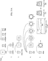
- FIG. 21A-28 A method of performing an assay using the immunoassay test slide 2 of the present invention will now be described, and reference should be had to Figures 21A-28 of the drawings.
- an assay is performed of thyroxine (T4) using an antibody-horseradish peroxidase conjugate.
- T4 thyroxine
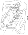
- Figure 22 illustrates a chemical analyzer 64 similar to that disclosed in the Rich, et al. published application, and related Figures 23-28 showing referenced components of the chemical analyzer.
- the assay consumables are envisioned to include the T4 slide; a "CTdx" diluent drawer package which includes a conjugate, a wash buffer and a substrate; and a sample, such as serum or plasma.
- the first step in the method is to load all of the consumables into the chemical analyzer. More specifically, one or more of the immunoassay test slides 2 of the present invention are loaded onto a slide inserter mechanism 20 (see Figure 23 ) (also reference no. 20 in the Rich, et al. application) situated behind doors 16 (see Figure 23 ) of the chemical analyzer (also reference no. 16 in the Rich, et al. application), which open to gain access to one of two slide inserter mechanisms.
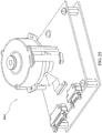
- the slide inserter mechanism loads the immunoassay test slide, among other chemical reagent test slides, onto a slide transport mechanism 26 (see Figure 24 ) (also reference no. 26 in the Rich, et al. application).
- the slide transport mechanism 26 selectively positions the immunoassay test slide under a fluid sample metering device 84 (see Figure 24 ) (also reference no. 84 in the Rich, et al. application) and above either or both of a reflectometer 684 (see Figure 25 ) (also reference no. 684 in the Rich, et al. application) and a fluorometer 654 (see Figure 26 ) (also reference no. 654 in the Rich, et al. application) to conduct colorimetric or fluorescence measurements.
- a fluid sample metering device 84 see Figure 24
- a reflectometer 684 see Figure 25
- a fluorometer 654 see Figure 26
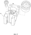
- a predetermined volume of fluid sample such as blood, serum or the like, is added to a sample vial 242 (see Figure 27 ) (also reference no. 242 in the Rich, et al. application), and the sample vial is placed on the slide inserter mechanism 20 in a well 206 (see Figure 27 ) (also reference no. 206 in the Rich, et al. application) for holding the vial.
- a sample vial 242 also reference no. 242 in the Rich, et al. application
- TMB detector reagent
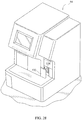
- separate vials containing a liquid conjugate reagent, a wash reagent and a detector reagent (TMB) can be loaded into respective wells formed in a diluent drawer 136 (see Figure 28 ) behind door 132 (see reference nos. 36 and 32 in the Rich, et al. application) of the chemical analyzer or in any other suitable location so long as the reagents are accessible to the analyzer's fluid metering system (see Step 1 in Figure 21
- Step 2 the fluid sample and the conjugate reagent are mixed by the metering device 84 of the chemical analyzer 64 either in a conjugate vial or in a separate empty vial situated in the diluent drawer 136 behind door 132.
- the mixing of the sample and conjugate may be performed in the manner disclosed in the Rich, et al. published application.
- the sample/conjugate mixture is then incubated within the chemical analyzer 64 at a predetermined temperature (for example, 37°C) for a predetermined period of time (for example, five minutes).
- a predetermined temperature for example, 37°C
- a predetermined period of time for example, five minutes.
- a relatively small amount (preferably 8 microliters) of the sample/conjugate mixture is dispensed on the immunoassay test slide 2 by the metering device 84 of the chemical analyzer, as set forth in Step 3 shown in Figure 21A .
- unbound T4-antibody*HRP binds to the immobilized capture reagent spot on the fluid flow matrix 12, which in the example shown is T3-PAA.
- One useable method of aspirating the sample/conjugate mixture from the vial and depositing the mixture on the immunoassay test slide 2 by the metering device 84 of the chemical analyzer is disclosed in the aforementioned Rich, et al. published application.
- the immunoassay test slide 2 is washed multiple times. More specifically, the test slide preferably undergoes four washes using 8 microliters of wash reagent for each wash dispensed by the metering device 84 of the chemical analyzer, each wash being preferably spaced apart in time by about 30 seconds.
- the metering device 84 of the chemical analyzer aspirates preferably at least 32 microliters of wash reagent from a vial in the diluent drawer containing such solution, and periodically dispenses preferably 8 microliters of the wash reagent onto the slide 2. With such washes, the T4-antibody*HRP bound to serum T4 is washed away.
- the wash solution is a liquid reagent that serves to remove unbound material from at least the central portion of the fluid flow matrix 12 situated above the bottom opening 40 in the bottom piece 8 or in the region of the matrix 12 which is subjected to measurement tests by the reflectometer or fluorometer.
- the wash reagent contains a surface active agent, such as a surfactant, or any other component capable of allowing the wash to wet the fluid flow matrix 12.
- Some other examples of wash reagents are alcohol (e.g. methanol) or any other water miscible organic solvent.
- Step 3 in Figure 21A There should be sufficient time allotted between dispensing the sample/conjugate mixture on the slide (Step 3 in Figure 21A ) and the start of the multiple wash step (Step 4 in Figure 21A ) to maximize the binding of the sample analyte to the specific binding reagent.
- the substrate, or detector reagent is dispensed on the immunoassay test slide 2 in a predetermined volume, preferably about 8 microliters (see Step 5 in Figure 21A ).
- the substrate, or detector reagent produces a detectable signal upon reaction with the enzyme-antibody conjugate at the central portion of the matrix 12.
- An example of a detector reagent, or substrate, which produces an insoluble end product following reaction with the enzyme, horseradish peroxidase, is tetramethybenzidine, or TMB, such as TMBlue, available from TSI Incorporated of Worcester, Massachusetts, Part no. TM 101.
- the end product produced by the TMBlue substrate is a dye that absorbs light.
- the T4-antibody*HRP bound to the spotted T3-PAA develops color, which is detectable by the reflectometer 684 of the chemical analyzer.
- a detector reagent, or substrate may be chosen to cause light to be emitted from the slide upon eradiation, e.g. fluorescence, by a fluorometer 654 of the chemical analyzer.
- the degree of color change of the matrix is reflective of the amount of analyte in the fluid sample.
- Figure 21B shows a graph plotting exemplary test results of reflectance measurements versus time for a T4 slide following the steps of the method described above and shown in Figure 21A .
- Reflectance measurements are preferably performed at 645 nanometers every 15 seconds on the T4 slide spotted with sample (labeled as "7.0 ug/dL T4" in Figure 21A ) and preferably a control T4 slide not spotted with sample (labeled as "0.0 ug/dL T4" in Figure 21A ).
- Exemplary reflectance measurements of both the sample T4 slide (shown by the line with diamonds) and the control T4 slide (shown by the line with squares) are plotted in the graph of Figure 21B .
- the manufacture and use of a Feline Pancreatic Lipase (fPL) immunoassay test slide will now be described.
- the fPL immunoassay test slide may have the structure shown in Figures 9-20 or the embodiments shown in Figures 1-4 , as will be described in greater detail.
- the porous matrix 12 which is preferably formed from a Fusion 5TM absorbent material, is placed into the slide housing 4 having a crystal clear (i.e., light transmissive) bottom side.
- Ten microliters of fPL 17A reagent particles are spotted onto the porous matrix (either on the top side or the bottom side of the matrix).
- the spotted slides are then dried in a drying tunnel for about 0.5 hour at about 95° Fahrenheit.
- the dried slides may then be used immediately or stored at preferably about 4° Celsius.
- a two-step protocol for testing for Feline Pancreatic Lipase is described below and shown in Figures 5 and 6 of the drawings. Sixteen microliters of sample are aspirated from a sample cup, and then dispensed onto the test slide at 4 microliter aliquot portions. Then, 16 microliters of conjugate are aspirated from the conjugate cup, and then dispensed onto the slide at 4 microliter aliquot portions. After this, 24 microliters of a wash buffer are aspirated from the wash cup, and then dispensed onto the slide at 4 microliter aliquot portions.
- TMB substrate i.e., a detector reagent
- TMB substrate i.e., a detector reagent
- blue color development of the spot of the matrix is recorded by optical reflectances (at 645 nanometers) for 60 seconds in preferably in one second intervals.
- the data is plotted, and the resulting linear curve fitted in ExcelTM to obtain the kinetic read of the assay.
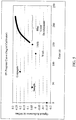
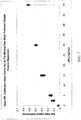
- the fPL progress curve and the fPL calibrated dose curve for this two-step protocol using the immunoassay test slide of the present invention are respectively shown in Figures 5 and 6 of the drawings.
- a one-step protocol using the fPL immunoassay test slide of the present invention will now be described.
- the sample and conjugate are mixed in the chemical analyzer's pipette tip beforehand and the mixture is then dispensed.
- An in-tip-mixing one-step protocol for testing a multiple of three fPL immunoassay slides is described below.
- 80 microliters of sample are first aspirated from the sample cup into the pipette tip of the chemical analyzer.
- 80 microliters of conjugate are then aspirated from the conjugate cup into the analyzer's pipette tip containing the sample.
- the sample and conjugate are mixed inside the analyzer's pipette tip for 10 seconds with a tip-mix-volume of 10 microliters.
- 15 microliters of the sample/conjugate premix are dispensed onto the immunoassay test slides of the present invention at 15 microliter aliquot portions preferably with a 90 second post-premix dispense time delay.
- the post-premix dispense time delay is preferably provided to permit sufficient incubation time for the immuno-reaction on the slides.
- the color change of the slide 2 detected by the reflectometer, or the fluorescence of the slide detected by the fluorometer, of the chemical analyzer may be measured quantitatively or qualitatively to determine the amount of analyte in the fluid sample (see Figure 21B and Step 6 in Figure 21A ).
- the immunoassay test slide 2 of the present invention may be loaded into the chemical analyzer with other immunoassay slides or with dry chemistry reagent test slides, the slides being tested concurrently.
- Another advantage of the immunoassay test slide over other conventional methods and devices for performing assays is the minute quantity of fluid sample and liquid reagents required for detecting the presence of an analyte in the fluid sample.
- the immunoassay test slide 2 may be formed by placing a die cut section of porous carrier matrix 12 from a sheet of the same material between a cover piece 6 and a bottom piece 8 of a plastic material, such as polystyrene, specifically shaped to be matable. The two pieces may be joined together by applying heat or an adhesive to define a substantially leakproof housing 4 in which resides the porous carrier matrix 12.
- the porous carrier matrix 12 may be spotted with an immobilized specific binding reagent prior to its insertion between the two mating slide pieces, or may be spotted with the specific binding reagent and heated to a specific temperature and for a predetermined period time to dry and immobilize the binding reagent in the central portion of the matrix 12.
- a bottom opening 40, formed in the bottom piece 8 of the immunoassay test slide 2 is provided, then prior to the insertion of the porous carrier matrix 12 between the cover piece 6 and the bottom piece 8, a thin sheet of transparent (clear) material 42, such as Mylar, is preferably used and placed within the interior cavity 10 defined by the slide housing 4 over the bottom opening 40.
- a transparent (clear) material 42 such as Mylar
- no such bottom opening or covering sheet is required if the bottom piece 8 of the slide is formed from a light transmissible or transparent material, such as polystyrene.
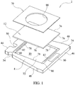
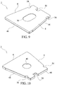
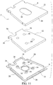
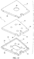
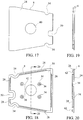
- the immunoassay test slide 2 of the present invention are shown in Figures 1-4 .
- Each of the test slides 2 of the invention includes a slide housing 4, a porous carrier matrix or membrane 12, such as described previously, and a film or cover sheet 70.
- the slide housing 4 is preferably trapezoidal in overall shape, but may be rectangular or square.
- the slide housing includes a front wall 44, a rear wall 46 situated opposite the front wall, and two opposite lateral walls 48. If the immunoassay test slide housing 4 is rectangular in shape, than each wall 44-48 is perpendicularly joined to its next adjacent wall. If the immunoassay test slide housing has a trapezoidal shape, such as shown in Figures 1-4 , then the front and rear walls 44, 46 are generally parallel to each other, and the rear wall 46 has a length which is greater than that of the front wall 44, and the opposite lateral walls 48 are non-parallel to each other and mutually converge from the rear wall 46 toward the front wall 44.
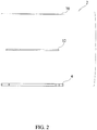
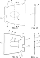
- the embodiment of the immunoassay test slide shown in Figure 4 is similar in structure to that of the immunoassay test slide shown in Figures 1-3 except that the two opposite lateral walls 48 are longer than those of the test slide shown in Figures 1-3 , giving the embodiment of the slide housing shown in Figure 4 an elongated trapezoidal shape.
- the immunoassay test slides 2 shown in Figures 1-4 may include an indexing notch 50 for proper orientation of the test slide on an analytical instrument, and lateral side recesses 54 used for loading the test slides on an analytical instrument, in the same manner and in the same locations as the notch and lateral side recesses included in the dry chemistry test slides disclosed in the aforementioned Heidt, et al. patent and the Rich, et al.
- the test slide housing 4 includes a recessed portion 72 of the top side 74 thereof to define a recess or cavity 10 which may be square, rectangular or even trapezoidal in shape.
- This cavity 10 is dimensioned to at least partially receive therein the porous carrier matrix 12.
- the matrix 12 performs the same function and may be made from the same material as the matrix described previously, that is, for holding a specific binding reagent and for absorbing a predetermined volume of fluid sample and conjugate reagent.
- the porous carrier matrix 12 is formed in the same manner as described previously, and is preferably dimensioned to be slightly smaller than the dimensions of the cavity 10 formed in the slide housing 4 so that its lateral edges 76 are spaced slightly away from the interior side walls 78 of the slide housing 4 defining the cavity 10 so as to define a channel or well 62 between the matrix 12 and the interior side walls 78 at least partially about the periphery of the housing.
- this channel or well 62 is provided to receive any overflow of fluid sample, reagent or wash solution from the matrix 12 which is envisioned to become saturated with such fluids.
- the well or channel 62 provides capacity in excess of the volume of fluid sample, reagents and wash solutions saturating the porous matrix 12.
- the preferred volume of the cavity 10 defined by the recessed portion 72 of the housing 4 is the same as that described previously.
- the preferred material from which the porous matrix 12 is formed is referred to by the trademark Fusion 5TM available from Whatman, Inc., USA, which is a glass fiber-based material that contains a plastic binder.
- the slide housing 4 is formed from crystal polystyrene, although it may be formed from the same materials which were described previously.
- the crystal polystyrene is transparent or at least translucent.
- a bottom opening 40 such as shown in Figure 10 , may be formed through the bottom side of the housing 4 if the housing is formed from a less light transmissive or opaque material.
- a transparent or clear (light transmissive) thin sheet of material 42 may be placed over the bottom opening and adhesively joined or heat sealed to the inner surface of the bottom side in alignment with the recess or cavity 10 of the slide housing, that is, interposed between the inner surface of the bottom side of the housing and the absorbent porous material 12, to insure the leakproofness of the housing 4.
- the crystal styrene material from which the slide housing 4 is preferably formed allows visible or infrared light, and more preferably, light at a wavelength of about 645 nanometers, to permeate therethrough.
- light emitted by the reflectometer 684 or fluorometer 652 of the analytical instrument will pass through the transparent bottom side of the slide housing 4 when the analytical instrument is conducting reflectance or fluorescence measurements on the immunoassay test slide.
- a recessed ledge 80 raised above the floor of the recessed portion 72 that receives the matrix 12 but slightly below the surface of the top side 74 of the slide housing, is formed on at least two opposite sides of the recess or cavity 10.
- each ledge 80 includes an elongated rib 82 which protrudes slightly above and outwardly from the top surface of the ledge 80.
- the elongated ribs 82 are used as "energy directors" and are provided for welding purposes.
- the ribs 82 bond to the flat underside surface of the covering film 70 to affix the covering film 70 to the slide housing 4 thereby securing the matrix 12 within the recess 10 under the film covering when the slide is being assembled.
- the top side 74 of the slide housing may include a bar code 86 situated thereon to identify the type of reagent used on the slide, which bar code 86 is read by an optical code reader forming part of the chemical analyzer.
- a thin polystyrene film 70 is placed over the porous matrix 12 and preferably resides in or above the recess or cavity 10 formed in the top side 74 of the slide housing 4.
- this polystyrene film 70 has a thickness of about .2 millimeters.
- the film 70 is preferably dimensioned to closely fit within the recess 10 in which the energy directors or ribs 82 reside, the opposite interior side walls 78 of the slide housing 10 being situated and dimensioned to help position the covering film 70 therebetween.
- the polystyrene covering film 70 includes an opening 88 formed through the thickness thereof, in much the same way as the cover piece 6 of the immunoassay test slides described previously has an opening 38.
- the top opening 88 is provided so that a precise amount of a sample fluid, such as blood, serum and the like, and reagents may be metered onto the test slide 2 and deposited on the porous matrix 12 situated under the opening 88, by a sample metering device 84 of the dry chemistry analytical instrument such as disclosed in the aforementioned Heidt et al. '229 patent and the Rich, et al. published application.
- This top opening 88 may be circular, as shown in Figures 1-3 , rectangular, or oval or elongated in shape, as shown in Figure 4 .
- the opening 88 formed through the top film portion 70 has a width along a minor axis thereof of between about 6 millimeters and about 12 millimeters, and more preferably about 10 millimeters, if the opening is oblong in shape, and has a diameter of between about 6 millimeters and about 12 millimeters, and more preferably about 10 millimeters, if the opening is circular in shape.
- the covering film 70 is situated on the test slide housing 4 by closely positioning the covering film within the recess 10 defined by the lateral walls 78 of the housing so that the film 70 completely covers the porous matrix 12 situated within the recess or cavity 10 of the slide housing.
- the covering film 70 may be joined to the slide housing 4 by an adhesive, or by sonic welding or heat stamping the film to the housing. Even more preferably, the underside surface of the film 70 rests on the ledges 80 and contacts the energy directors or ribs 82, and the film 70 is joined to the ledges 80 by sonic welding using the energy directors 82.
Claims (10)
- Lame de test (2) pour essai immunologique, qui comprend :- un boîtier (4), le boîtier (4) définissant une cavité (10) ; et- une matrice porteuse poreuse (12), la matrice porteuse poreuse (12) étant disposée à l'intérieur de la cavité (10) du boîtier (4) pour recevoir un échantillon de fluide contenant un analyte, ou un ou plusieurs réactifs liquides ; dans laquelle le boîtier (4) inclut un côté inférieur qui est formé d'un matériau qui transmet la lumière, un côté supérieur (74), le côté supérieur (74) incluant une portion évidée (72) pour définir au moins partiellement la cavité (10) destinée à recevoir la matrice porteuse poreuse (12), un côté avant (44), un côté arrière (46) situé à l'opposé du côté avant (44), et des côtés latéraux opposés (48), la cavité (10) étant située entre le côté avant et le côté arrière (44, 46) et entre les côtés latéraux opposés (48) du boîtier (4) ;et dans laquelle la lame de test (2) comprend en outre :une portion supérieure en film (70), la portion supérieure en film (70) étant située sur le boîtier (4) à l'opposé du côté inférieur et en alignement avec la matrice porteuse poreuse (12) de manière à couvrir celle-ci, la portion supérieure en film (70) ayant une ouverture (88) formée à travers l'épaisseur de celle-ci, qui communique avec la cavité (10) du boîtier (4) et qui est prévue pour recevoir l'échantillon de fluide contenant un analyte ou lesdits un ou plusieurs réactifs liquides, la matrice porteuse poreuse (12) étant disposée à l'intérieur du boîtier (4) et située en alignement avec l'ouverture supérieure (88) formée dans la portion en film (70) afin de recevoir sur celle-ci l'échantillon de fluide ou lesdits un ou plusieurs réactifs liquides ; etdans laquelle le côté supérieur (74) du boîtier (4) inclut au moins un rebord évidé (80), ledit au moins un rebord évidé (80) étant situé adjacent à la portion évidée (72) qui reçoit la matrice porteuse poreuse (12), ledit au moins un rebord évidé (80) ayant une surface supérieure sur laquelle repose une portion de la surface du côté inférieur de la portion supérieure en film (70).
- Lame de test pour essai immunologique (2) selon la revendication 1, dans laquelle le boîtier (4) a une forme généralement trapézoïdale, et dans laquelle le côté avant et le côté arrière (44, 46) du boîtier (4) sont généralement parallèles l'un à l'autre et le côté arrière (46) est plus long que le côté avant (44).
- Lame de test pour essai immunologique (2) selon la revendication 1, dans lequel la portion supérieure en film (70) est formée d'un matériau à base de polystyrène.
- Lame de test pour essai immunologique (2) selon la revendication 1, dans laquelle la portion supérieure en film (70) a une épaisseur de 0,2 mm.
- Lame de test pour essai immunologique (2) selon la revendication 1, dans laquelle l'ouverture (88) formée à travers la portion supérieure en film (70) est soit circulaire soit oblongue.
- Lame de test pour essai immunologique (2) selon la revendication 5, dans laquelle l'ouverture (88) formée à travers la portion supérieure en film (70) présente une largeur le long de son petit axe, comprise entre 6 mm et 12 mm si l'ouverture (88) a une forme oblongue, et possède un diamètre entre 6 mm et 12 mm si l'ouverture (88) est de forme circulaire.
- Lame de test pour essai immunologique (2) selon la revendication 1, dans laquelle la matrice porteuse poreuse (12) est formée à partir d'un matériau à base de fibres de verre qui contient un liant en matière plastique.
- Lame de test pour essai immunologique (2) selon la revendication 1, dans laquelle le boîtier de la lame (4) est formé d'un matériau à base de polystyrène.
- Lame de test pour essai immunologique (2) selon la revendication 1, dans laquelle le côté supérieur (74) du boîtier de la lame (4) inclut un code à barres (86) situé sur celui-ci.
- Lame de test pour essai immunologique (2) selon la revendication 1, dans laquelle le boîtier (4) inclut une paroi latérale (78) qui entoure la cavité (10), au moins une portion de la paroi latérale (78) étant espacée latéralement depuis la matrice porteuse poreuse (12) pour définir entre celles-ci un canal (62) pour recevoir un volume en excès de l'échantillon de fluide ou desdits un ou plusieurs réactifs liquides.
Applications Claiming Priority (2)
| Application Number | Priority Date | Filing Date | Title |
|---|---|---|---|
| US201261585050P | 2012-01-10 | 2012-01-10 | |
| PCT/US2013/020483 WO2013106269A2 (fr) | 2012-01-10 | 2013-01-07 | Lame d'essai d'immunodosage |
Publications (3)
| Publication Number | Publication Date |
|---|---|
| EP2802869A2 EP2802869A2 (fr) | 2014-11-19 |
| EP2802869A4 EP2802869A4 (fr) | 2015-12-09 |
| EP2802869B1 true EP2802869B1 (fr) | 2018-03-07 |
Family
ID=48782068
Family Applications (1)
| Application Number | Title | Priority Date | Filing Date |
|---|---|---|---|
| EP13736046.7A Active EP2802869B1 (fr) | 2012-01-10 | 2013-01-07 | Lame d'essai d'immunodosage |
Country Status (8)
| Country | Link |
|---|---|
| US (2) | US9933428B2 (fr) |
| EP (1) | EP2802869B1 (fr) |
| JP (1) | JP6373191B2 (fr) |
| CN (1) | CN104204794B (fr) |
| AU (1) | AU2013208289B2 (fr) |
| CA (1) | CA2857522C (fr) |
| ES (1) | ES2672268T3 (fr) |
| WO (1) | WO2013106269A2 (fr) |
Cited By (1)
| Publication number | Priority date | Publication date | Assignee | Title |
|---|---|---|---|---|
| EP3368220A4 (fr) * | 2015-10-26 | 2019-03-20 | IDEXX Laboratories, Inc. | Lame de test d'hématologie |
Families Citing this family (4)
| Publication number | Priority date | Publication date | Assignee | Title |
|---|---|---|---|---|
| WO2013106269A2 (fr) * | 2012-01-10 | 2013-07-18 | Idexx Laboratories, Inc. | Lame d'essai d'immunodosage |
| WO2015106008A1 (fr) | 2014-01-10 | 2015-07-16 | Idexx Laboratories, Inc. | Analyseur chimique |
| CN107250795B (zh) | 2015-02-20 | 2021-07-30 | 艾德克斯实验室公司 | 带有对背景信号的补偿的均相免疫测定 |
| MX2020003523A (es) | 2017-10-19 | 2020-07-22 | Idexx Lab Inc | Deteccion de dimetilarginina simetrica. |
Family Cites Families (57)
| Publication number | Priority date | Publication date | Assignee | Title |
|---|---|---|---|---|
| JPH0131957Y2 (fr) * | 1980-03-28 | 1989-10-02 | ||
| JPS56142454A (en) | 1980-04-09 | 1981-11-06 | Nippon Kokan Kk <Nkk> | Steel pipe's upset flaw inspecting device |
| IE903118A1 (en) * | 1989-09-21 | 1991-03-27 | Becton Dickinson Co | Test device including flow control means |
| US5185127A (en) | 1989-09-21 | 1993-02-09 | Becton, Dickinson And Company | Test device including flow control means |
| US5089229A (en) | 1989-11-22 | 1992-02-18 | Vettest S.A. | Chemical analyzer |
| US5376551A (en) * | 1991-03-12 | 1994-12-27 | University Of Utah Research Foundation | Apparatus for using fluorescently labeled ligands in studying interaction of a native ligand and its receptor |
| US5726010A (en) | 1991-07-31 | 1998-03-10 | Idexx Laboratories, Inc. | Reversible flow chromatographic binding assay |
| JP3299330B2 (ja) | 1993-03-18 | 2002-07-08 | 持田製薬株式会社 | 簡易測定装置および方法 |
| ATE224053T1 (de) * | 1993-11-12 | 2002-09-15 | Inverness Medical Switzerland | Vorrichtung zum ablesen von teststreifen |
| JPH07191020A (ja) * | 1993-12-27 | 1995-07-28 | Fuji Photo Film Co Ltd | 全血分析要素を用いた全血試料の分析方法 |
| GB9419267D0 (en) | 1994-09-23 | 1994-11-09 | Unilever Plc | Assay devices |
| US5597532A (en) | 1994-10-20 | 1997-01-28 | Connolly; James | Apparatus for determining substances contained in a body fluid |
| IL113920A (en) | 1995-05-30 | 1999-09-22 | Avraham Reinhartz | Apparatus and method for detection of analytes in a sample |
| US5962215A (en) * | 1996-04-05 | 1999-10-05 | Mercury Diagnostics, Inc. | Methods for testing the concentration of an analyte in a body fluid |
| US5770441A (en) * | 1996-09-30 | 1998-06-23 | Lipton; Stewart | Methods, apparatuses and kits for the growth and/or identification of microorganisms |
| WO1999023475A1 (fr) | 1997-10-31 | 1999-05-14 | Dade Behring Inc. | Dispositif d'analyse chromogene et turbidimetrique |
| US6344333B2 (en) * | 1998-09-08 | 2002-02-05 | Synectig Corporation | Reagent-free immunoassay monitoring electrode assembly |
| DE60043049D1 (de) | 1999-12-28 | 2009-11-12 | Arkray Inc | Bluttestvorrichtung |
| US20020025278A1 (en) * | 2001-01-09 | 2002-02-28 | Gel Manipulation Apparatus | Gel manipulation apparatus |
| AU2001275277B2 (en) * | 2000-06-02 | 2005-05-19 | Biocontrol Systems, Inc. | Self-contained devices for detecting biological contaminants |
| US7041468B2 (en) | 2001-04-02 | 2006-05-09 | Therasense, Inc. | Blood glucose tracking apparatus and methods |
| WO2002084291A1 (fr) * | 2001-04-12 | 2002-10-24 | Arkray, Inc. | Instrument d'analyse de prelevement |
| US6890484B2 (en) * | 2001-05-18 | 2005-05-10 | Acon Laboratories, Inc. | In line test device and methods of use |
| DE10126583C2 (de) * | 2001-05-31 | 2003-05-08 | Envitec Wismar Gmbh | Vorrichtung zum Sammeln von flüssigen Proben |
| US6977722B2 (en) * | 2001-06-29 | 2005-12-20 | Meso Scale Technologies, Llc. | Assay plates, reader systems and methods for luminescence test measurements |
| EP1474692B1 (fr) | 2001-12-28 | 2014-12-17 | Polymer Technology Systems, Inc. | Batonnet diagnostique permettant de determiner une concentration de plusieurs analytes dans un echantillon de fluide unique |
| US7220573B2 (en) * | 2002-06-21 | 2007-05-22 | Agilent Technologies, Inc. | Array assay devices and methods of using the same |
| US7025864B2 (en) * | 2003-03-10 | 2006-04-11 | Elchrom Scientific A.G. | Method and apparatus for recovering target molecules from a gel containing said target molecules |
| DE10321320A1 (de) * | 2003-05-13 | 2004-12-02 | Degussa Ag | Organofunktionelle Siloxangemische |
| DE102004041595A1 (de) * | 2004-04-30 | 2005-12-01 | Markus Gruber | Messzelle sowie Verfahren zum Herstellen einer Messzelle und Messvorrichtung zur Aufnahme einer derartigen Messzelle |
| US20090054255A1 (en) * | 2004-07-01 | 2009-02-26 | The Regents Of The University Of California | Microfluidic devices and methods |
| JP2006098229A (ja) * | 2004-09-29 | 2006-04-13 | Fuji Photo Film Co Ltd | 生化学分析装置 |
| AU2005301045B2 (en) * | 2004-11-01 | 2012-10-18 | International Bio-Therapeutic Research Inc. | Disposable immunodiagnostic test system |
| US8475735B2 (en) | 2004-11-01 | 2013-07-02 | Uma Mahesh Babu | Disposable immunodiagnostic test system |
| JP2008522160A (ja) * | 2004-11-24 | 2008-06-26 | アイデックス ラボラトリーズ インコーポレイテッド | 化学分析装置において使用する反射率計および関連の光源 |
| US20060199276A1 (en) * | 2005-03-07 | 2006-09-07 | Bernhard Armani | Device for multiple rapid detection and testing of diseases, disorders and immunity in human, animals and the environment |
| JP2008533989A (ja) * | 2005-03-22 | 2008-08-28 | アイアールエム・リミテッド・ライアビリティ・カンパニー | 化合物をプロファイル解析するデバイス、システムおよび関連方法 |
| WO2006105110A2 (fr) * | 2005-03-29 | 2006-10-05 | Inverness Medical Switzerland Gmbh | Dispositifs de dosage et procedes |
| WO2006119203A2 (fr) * | 2005-04-29 | 2006-11-09 | Beckman Coulter | Dosage immunologique a ecoulement lateral par fluorescence |
| WO2007009125A2 (fr) * | 2005-07-14 | 2007-01-18 | Nano-Ditech Corporation | Dispositifs microfluidiques et leurs methodes de preparation et d'utilisation |
| US7816122B2 (en) * | 2005-10-18 | 2010-10-19 | Idexx Laboratories, Inc. | Lateral flow device with onboard reagents |
| US20070092401A1 (en) * | 2005-10-26 | 2007-04-26 | Feier Liao | Devices and methods for sample collection and analysis |
| AU2007217765A1 (en) * | 2006-02-21 | 2007-08-30 | Nanogen, Inc. | Methods and compositions for analyte detection |
| WO2008063135A1 (fr) * | 2006-11-24 | 2008-05-29 | Agency For Science, Technology And Research | Appareil pour traiter un échantillon dans une gouttelette de liquide et procédé d'utilisation |
| US8357538B2 (en) * | 2007-04-06 | 2013-01-22 | Qiagen Gaithersburg, Inc. | Automated assay and system |
| WO2008140742A1 (fr) | 2007-05-08 | 2008-11-20 | Idexx Laboratories, Inc. | Analyseur chimique |
| CN102047102A (zh) * | 2008-05-27 | 2011-05-04 | 皇家飞利浦电子股份有限公司 | 等电聚焦生物芯片 |
| US9103785B2 (en) * | 2008-06-25 | 2015-08-11 | Emergence Genomics, Llc | Method and apparatus for melting curve analysis of nucleic acids in microarray format |
| WO2010042766A1 (fr) * | 2008-10-08 | 2010-04-15 | Sage Science, Inc. | Système d'électrophorèse préparatoire à canaux multiples |
| US8361299B2 (en) * | 2008-10-08 | 2013-01-29 | Sage Science, Inc. | Multichannel preparative electrophoresis system |
| US8784752B2 (en) * | 2009-04-17 | 2014-07-22 | Curiox Biosystems Pte Ltd | Use of chemically patterned substrate for liquid handling, chemical and biological reactions |
| CN201449486U (zh) | 2009-06-24 | 2010-05-05 | 贾璋林 | 一种带有多个反应池的多功能载玻片 |
| CN201540288U (zh) | 2009-07-09 | 2010-08-04 | 上海科华生物工程股份有限公司 | 定量测定人体血液尿素含量的干化学试纸 |
| US9588111B2 (en) * | 2009-11-24 | 2017-03-07 | Ingibio, Ltd. | Membrane biosensor having multi-hole film attached thereto and method for measuring immunological reaction or enzymatic reaction using the same |
| AU2011236503B2 (en) | 2010-04-07 | 2014-10-30 | Biosensia Patents Limited | Flow control device for assays |
| US8815532B2 (en) * | 2011-06-07 | 2014-08-26 | Diagnostic Innovations, Llc | Color-producing diagnostic systems, reagents and methods |
| WO2013106269A2 (fr) * | 2012-01-10 | 2013-07-18 | Idexx Laboratories, Inc. | Lame d'essai d'immunodosage |
-
2013
- 2013-01-07 WO PCT/US2013/020483 patent/WO2013106269A2/fr active Application Filing
- 2013-01-07 US US14/358,280 patent/US9933428B2/en active Active
- 2013-01-07 AU AU2013208289A patent/AU2013208289B2/en active Active
- 2013-01-07 JP JP2014552226A patent/JP6373191B2/ja active Active
- 2013-01-07 CN CN201380005166.6A patent/CN104204794B/zh active Active
- 2013-01-07 CA CA2857522A patent/CA2857522C/fr active Active
- 2013-01-07 ES ES13736046.7T patent/ES2672268T3/es active Active
- 2013-01-07 EP EP13736046.7A patent/EP2802869B1/fr active Active
-
2018
- 2018-02-28 US US15/908,313 patent/US11047857B2/en active Active
Non-Patent Citations (1)
| Title |
|---|
| None * |
Cited By (1)
| Publication number | Priority date | Publication date | Assignee | Title |
|---|---|---|---|---|
| EP3368220A4 (fr) * | 2015-10-26 | 2019-03-20 | IDEXX Laboratories, Inc. | Lame de test d'hématologie |
Also Published As
| Publication number | Publication date |
|---|---|
| CN104204794B (zh) | 2017-07-11 |
| WO2013106269A2 (fr) | 2013-07-18 |
| CA2857522C (fr) | 2020-04-14 |
| ES2672268T3 (es) | 2018-06-13 |
| JP2015505054A (ja) | 2015-02-16 |
| AU2013208289B2 (en) | 2016-08-11 |
| EP2802869A4 (fr) | 2015-12-09 |
| US20180188250A1 (en) | 2018-07-05 |
| US9933428B2 (en) | 2018-04-03 |
| US20140315216A1 (en) | 2014-10-23 |
| AU2013208289A1 (en) | 2014-08-28 |
| CN104204794A (zh) | 2014-12-10 |
| JP6373191B2 (ja) | 2018-08-15 |
| EP2802869A2 (fr) | 2014-11-19 |
| CA2857522A1 (fr) | 2013-07-18 |
| WO2013106269A3 (fr) | 2014-09-04 |
| US11047857B2 (en) | 2021-06-29 |
Similar Documents
| Publication | Publication Date | Title |
|---|---|---|
| US11047857B2 (en) | Immunoassay test slide | |
| US8470588B2 (en) | Rotatable test element | |
| AU2001253354B8 (en) | Diagnostic device with multiple independent flow paths | |
| US9857365B2 (en) | Freeze-dried conjugate structure for point-of-care testing (POCT) immunochromatography, immunoassay kit comprising the same, and method for analysis using the kit | |
| US7816122B2 (en) | Lateral flow device with onboard reagents | |
| CA2280902C (fr) | Cassette pour dosages immunologiques automatises | |
| EP0296415B1 (fr) | Plaque à plusieurs trous contenant des insertions de membrane | |
| US9709562B2 (en) | Lateral flow assay devices for use in clinical diagnostic apparatus and configuration of clinical diagnostic apparatus for same | |
| US5288648A (en) | Multiwell stat test | |
| AU2001253354A1 (en) | Diagnostic device with multiple independent flow paths | |
| WO2005029073A2 (fr) | Procedes et dispositif de dosage chromatographique | |
| EP1436621B1 (fr) | Dispositif de test multi-analytes a zone de detection multipoints | |
| US20030073121A1 (en) | Multi-analyte assay device with multi-spot detection zone | |
| US20210055284A1 (en) | Microchip immunoassay device having precise incubation time control and signal scaling and related methods | |
| EP0439917A1 (fr) | Appareil pour la détection et la mesure semiquantitative de composés | |
| US20130337580A1 (en) | Immunoassay Device and Method |
Legal Events
| Date | Code | Title | Description |
|---|---|---|---|
| PUAI | Public reference made under article 153(3) epc to a published international application that has entered the european phase |
Free format text: ORIGINAL CODE: 0009012 |
|
| 17P | Request for examination filed |
Effective date: 20140728 |
|
| AK | Designated contracting states |
Kind code of ref document: A2 Designated state(s): AL AT BE BG CH CY CZ DE DK EE ES FI FR GB GR HR HU IE IS IT LI LT LU LV MC MK MT NL NO PL PT RO RS SE SI SK SM TR |
|
| RIN1 | Information on inventor provided before grant (corrected) |
Inventor name: CHAN, EUGENE Inventor name: NASSIF, KEITH |
|
| DAX | Request for extension of the european patent (deleted) | ||
| RIC1 | Information provided on ipc code assigned before grant |
Ipc: G01N 33/543 20060101AFI20150716BHEP |
|
| A4 | Supplementary search report drawn up and despatched |
Effective date: 20151109 |
|
| RIC1 | Information provided on ipc code assigned before grant |
Ipc: G01N 33/543 20060101AFI20151103BHEP |
|
| STAA | Information on the status of an ep patent application or granted ep patent |
Free format text: STATUS: REQUEST FOR EXAMINATION WAS MADE |
|
| R17P | Request for examination filed (corrected) |
Effective date: 20140728 |
|
| REG | Reference to a national code |
Ref country code: DE Ref legal event code: R079 Ref document number: 602013034035 Country of ref document: DE Free format text: PREVIOUS MAIN CLASS: G01N0033240000 Ipc: G01N0035000000 |
|
| RIC1 | Information provided on ipc code assigned before grant |
Ipc: G01N 35/00 20060101AFI20170621BHEP Ipc: G01N 33/543 20060101ALI20170621BHEP |
|
| GRAP | Despatch of communication of intention to grant a patent |
Free format text: ORIGINAL CODE: EPIDOSNIGR1 |
|
| STAA | Information on the status of an ep patent application or granted ep patent |
Free format text: STATUS: GRANT OF PATENT IS INTENDED |
|
| INTG | Intention to grant announced |
Effective date: 20170731 |
|
| RIN1 | Information on inventor provided before grant (corrected) |
Inventor name: NASSIF, KEITH Inventor name: CHAN, EUGENE |
|
| GRAS | Grant fee paid |
Free format text: ORIGINAL CODE: EPIDOSNIGR3 |
|
| GRAA | (expected) grant |
Free format text: ORIGINAL CODE: 0009210 |
|
| STAA | Information on the status of an ep patent application or granted ep patent |
Free format text: STATUS: THE PATENT HAS BEEN GRANTED |
|
| AK | Designated contracting states |
Kind code of ref document: B1 Designated state(s): AL AT BE BG CH CY CZ DE DK EE ES FI FR GB GR HR HU IE IS IT LI LT LU LV MC MK MT NL NO PL PT RO RS SE SI SK SM TR |
|
| REG | Reference to a national code |
Ref country code: GB Ref legal event code: FG4D |
|
| REG | Reference to a national code |
Ref country code: CH Ref legal event code: EP Ref country code: AT Ref legal event code: REF Ref document number: 977130 Country of ref document: AT Kind code of ref document: T Effective date: 20180315 |
|
| REG | Reference to a national code |
Ref country code: IE Ref legal event code: FG4D |
|
| REG | Reference to a national code |
Ref country code: DE Ref legal event code: R096 Ref document number: 602013034035 Country of ref document: DE |
|
| REG | Reference to a national code |
Ref country code: NL Ref legal event code: FP |
|
| REG | Reference to a national code |
Ref country code: ES Ref legal event code: FG2A Ref document number: 2672268 Country of ref document: ES Kind code of ref document: T3 Effective date: 20180613 |
|
| REG | Reference to a national code |
Ref country code: LT Ref legal event code: MG4D |
|
| PG25 | Lapsed in a contracting state [announced via postgrant information from national office to epo] |
Ref country code: LT Free format text: LAPSE BECAUSE OF FAILURE TO SUBMIT A TRANSLATION OF THE DESCRIPTION OR TO PAY THE FEE WITHIN THE PRESCRIBED TIME-LIMIT Effective date: 20180307 Ref country code: NO Free format text: LAPSE BECAUSE OF FAILURE TO SUBMIT A TRANSLATION OF THE DESCRIPTION OR TO PAY THE FEE WITHIN THE PRESCRIBED TIME-LIMIT Effective date: 20180607 Ref country code: HR Free format text: LAPSE BECAUSE OF FAILURE TO SUBMIT A TRANSLATION OF THE DESCRIPTION OR TO PAY THE FEE WITHIN THE PRESCRIBED TIME-LIMIT Effective date: 20180307 Ref country code: FI Free format text: LAPSE BECAUSE OF FAILURE TO SUBMIT A TRANSLATION OF THE DESCRIPTION OR TO PAY THE FEE WITHIN THE PRESCRIBED TIME-LIMIT Effective date: 20180307 Ref country code: CY Free format text: LAPSE BECAUSE OF FAILURE TO SUBMIT A TRANSLATION OF THE DESCRIPTION OR TO PAY THE FEE WITHIN THE PRESCRIBED TIME-LIMIT Effective date: 20180307 |
|
| REG | Reference to a national code |
Ref country code: AT Ref legal event code: MK05 Ref document number: 977130 Country of ref document: AT Kind code of ref document: T Effective date: 20180307 |
|
| PG25 | Lapsed in a contracting state [announced via postgrant information from national office to epo] |
Ref country code: SE Free format text: LAPSE BECAUSE OF FAILURE TO SUBMIT A TRANSLATION OF THE DESCRIPTION OR TO PAY THE FEE WITHIN THE PRESCRIBED TIME-LIMIT Effective date: 20180307 Ref country code: LV Free format text: LAPSE BECAUSE OF FAILURE TO SUBMIT A TRANSLATION OF THE DESCRIPTION OR TO PAY THE FEE WITHIN THE PRESCRIBED TIME-LIMIT Effective date: 20180307 Ref country code: GR Free format text: LAPSE BECAUSE OF FAILURE TO SUBMIT A TRANSLATION OF THE DESCRIPTION OR TO PAY THE FEE WITHIN THE PRESCRIBED TIME-LIMIT Effective date: 20180608 Ref country code: BG Free format text: LAPSE BECAUSE OF FAILURE TO SUBMIT A TRANSLATION OF THE DESCRIPTION OR TO PAY THE FEE WITHIN THE PRESCRIBED TIME-LIMIT Effective date: 20180607 Ref country code: RS Free format text: LAPSE BECAUSE OF FAILURE TO SUBMIT A TRANSLATION OF THE DESCRIPTION OR TO PAY THE FEE WITHIN THE PRESCRIBED TIME-LIMIT Effective date: 20180307 |
|
| PG25 | Lapsed in a contracting state [announced via postgrant information from national office to epo] |
Ref country code: AL Free format text: LAPSE BECAUSE OF FAILURE TO SUBMIT A TRANSLATION OF THE DESCRIPTION OR TO PAY THE FEE WITHIN THE PRESCRIBED TIME-LIMIT Effective date: 20180307 Ref country code: PL Free format text: LAPSE BECAUSE OF FAILURE TO SUBMIT A TRANSLATION OF THE DESCRIPTION OR TO PAY THE FEE WITHIN THE PRESCRIBED TIME-LIMIT Effective date: 20180307 Ref country code: EE Free format text: LAPSE BECAUSE OF FAILURE TO SUBMIT A TRANSLATION OF THE DESCRIPTION OR TO PAY THE FEE WITHIN THE PRESCRIBED TIME-LIMIT Effective date: 20180307 Ref country code: RO Free format text: LAPSE BECAUSE OF FAILURE TO SUBMIT A TRANSLATION OF THE DESCRIPTION OR TO PAY THE FEE WITHIN THE PRESCRIBED TIME-LIMIT Effective date: 20180307 |
|
| PG25 | Lapsed in a contracting state [announced via postgrant information from national office to epo] |
Ref country code: SM Free format text: LAPSE BECAUSE OF FAILURE TO SUBMIT A TRANSLATION OF THE DESCRIPTION OR TO PAY THE FEE WITHIN THE PRESCRIBED TIME-LIMIT Effective date: 20180307 Ref country code: CZ Free format text: LAPSE BECAUSE OF FAILURE TO SUBMIT A TRANSLATION OF THE DESCRIPTION OR TO PAY THE FEE WITHIN THE PRESCRIBED TIME-LIMIT Effective date: 20180307 Ref country code: SK Free format text: LAPSE BECAUSE OF FAILURE TO SUBMIT A TRANSLATION OF THE DESCRIPTION OR TO PAY THE FEE WITHIN THE PRESCRIBED TIME-LIMIT Effective date: 20180307 Ref country code: AT Free format text: LAPSE BECAUSE OF FAILURE TO SUBMIT A TRANSLATION OF THE DESCRIPTION OR TO PAY THE FEE WITHIN THE PRESCRIBED TIME-LIMIT Effective date: 20180307 |
|
| REG | Reference to a national code |
Ref country code: DE Ref legal event code: R097 Ref document number: 602013034035 Country of ref document: DE |
|
| PG25 | Lapsed in a contracting state [announced via postgrant information from national office to epo] |
Ref country code: PT Free format text: LAPSE BECAUSE OF FAILURE TO SUBMIT A TRANSLATION OF THE DESCRIPTION OR TO PAY THE FEE WITHIN THE PRESCRIBED TIME-LIMIT Effective date: 20180709 |
|
| PLBE | No opposition filed within time limit |
Free format text: ORIGINAL CODE: 0009261 |
|
| STAA | Information on the status of an ep patent application or granted ep patent |
Free format text: STATUS: NO OPPOSITION FILED WITHIN TIME LIMIT |
|
| PG25 | Lapsed in a contracting state [announced via postgrant information from national office to epo] |
Ref country code: DK Free format text: LAPSE BECAUSE OF FAILURE TO SUBMIT A TRANSLATION OF THE DESCRIPTION OR TO PAY THE FEE WITHIN THE PRESCRIBED TIME-LIMIT Effective date: 20180307 |
|
| 26N | No opposition filed |
Effective date: 20181210 |
|
| PG25 | Lapsed in a contracting state [announced via postgrant information from national office to epo] |
Ref country code: SI Free format text: LAPSE BECAUSE OF FAILURE TO SUBMIT A TRANSLATION OF THE DESCRIPTION OR TO PAY THE FEE WITHIN THE PRESCRIBED TIME-LIMIT Effective date: 20180307 |
|
| PG25 | Lapsed in a contracting state [announced via postgrant information from national office to epo] |
Ref country code: MC Free format text: LAPSE BECAUSE OF FAILURE TO SUBMIT A TRANSLATION OF THE DESCRIPTION OR TO PAY THE FEE WITHIN THE PRESCRIBED TIME-LIMIT Effective date: 20180307 |
|
| REG | Reference to a national code |
Ref country code: CH Ref legal event code: PL |
|
| PG25 | Lapsed in a contracting state [announced via postgrant information from national office to epo] |
Ref country code: LU Free format text: LAPSE BECAUSE OF NON-PAYMENT OF DUE FEES Effective date: 20190107 |
|
| REG | Reference to a national code |
Ref country code: BE Ref legal event code: MM Effective date: 20190131 |
|
| REG | Reference to a national code |
Ref country code: IE Ref legal event code: MM4A |
|
| PG25 | Lapsed in a contracting state [announced via postgrant information from national office to epo] |
Ref country code: BE Free format text: LAPSE BECAUSE OF NON-PAYMENT OF DUE FEES Effective date: 20190131 |
|
| PG25 | Lapsed in a contracting state [announced via postgrant information from national office to epo] |
Ref country code: LI Free format text: LAPSE BECAUSE OF NON-PAYMENT OF DUE FEES Effective date: 20190131 Ref country code: CH Free format text: LAPSE BECAUSE OF NON-PAYMENT OF DUE FEES Effective date: 20190131 |
|
| PG25 | Lapsed in a contracting state [announced via postgrant information from national office to epo] |
Ref country code: IE Free format text: LAPSE BECAUSE OF NON-PAYMENT OF DUE FEES Effective date: 20190107 |
|
| PG25 | Lapsed in a contracting state [announced via postgrant information from national office to epo] |
Ref country code: TR Free format text: LAPSE BECAUSE OF FAILURE TO SUBMIT A TRANSLATION OF THE DESCRIPTION OR TO PAY THE FEE WITHIN THE PRESCRIBED TIME-LIMIT Effective date: 20180307 |
|
| PG25 | Lapsed in a contracting state [announced via postgrant information from national office to epo] |
Ref country code: MT Free format text: LAPSE BECAUSE OF NON-PAYMENT OF DUE FEES Effective date: 20190107 |
|
| PG25 | Lapsed in a contracting state [announced via postgrant information from national office to epo] |
Ref country code: IS Free format text: LAPSE BECAUSE OF FAILURE TO SUBMIT A TRANSLATION OF THE DESCRIPTION OR TO PAY THE FEE WITHIN THE PRESCRIBED TIME-LIMIT Effective date: 20180707 |
|
| PG25 | Lapsed in a contracting state [announced via postgrant information from national office to epo] |
Ref country code: HU Free format text: LAPSE BECAUSE OF FAILURE TO SUBMIT A TRANSLATION OF THE DESCRIPTION OR TO PAY THE FEE WITHIN THE PRESCRIBED TIME-LIMIT; INVALID AB INITIO Effective date: 20130107 |
|
| PG25 | Lapsed in a contracting state [announced via postgrant information from national office to epo] |
Ref country code: MK Free format text: LAPSE BECAUSE OF FAILURE TO SUBMIT A TRANSLATION OF THE DESCRIPTION OR TO PAY THE FEE WITHIN THE PRESCRIBED TIME-LIMIT Effective date: 20180307 |
|
| PGFP | Annual fee paid to national office [announced via postgrant information from national office to epo] |
Ref country code: FR Payment date: 20230125 Year of fee payment: 11 Ref country code: ES Payment date: 20230201 Year of fee payment: 11 |
|
| PGFP | Annual fee paid to national office [announced via postgrant information from national office to epo] |
Ref country code: IT Payment date: 20230120 Year of fee payment: 11 Ref country code: GB Payment date: 20230127 Year of fee payment: 11 Ref country code: DE Payment date: 20230127 Year of fee payment: 11 |
|
| P01 | Opt-out of the competence of the unified patent court (upc) registered |
Effective date: 20230522 |
|
| PGFP | Annual fee paid to national office [announced via postgrant information from national office to epo] |
Ref country code: NL Payment date: 20230126 Year of fee payment: 11 |
|
| PGFP | Annual fee paid to national office [announced via postgrant information from national office to epo] |
Ref country code: NL Payment date: 20240126 Year of fee payment: 12 |
|
| PGFP | Annual fee paid to national office [announced via postgrant information from national office to epo] |
Ref country code: ES Payment date: 20240201 Year of fee payment: 12 |