EP2802779B1 - Compressor for pressurized fluid output - Google Patents
Compressor for pressurized fluid output Download PDFInfo
- Publication number
- EP2802779B1 EP2802779B1 EP13736400.6A EP13736400A EP2802779B1 EP 2802779 B1 EP2802779 B1 EP 2802779B1 EP 13736400 A EP13736400 A EP 13736400A EP 2802779 B1 EP2802779 B1 EP 2802779B1
- Authority
- EP
- European Patent Office
- Prior art keywords
- compressor
- rotating shaft
- piston rod
- piston
- seal
- Prior art date
- Legal status (The legal status is an assumption and is not a legal conclusion. Google has not performed a legal analysis and makes no representation as to the accuracy of the status listed.)
- Not-in-force
Links
- 239000012530 fluid Substances 0.000 title description 11
- 239000007789 gas Substances 0.000 description 13
- 230000009977 dual effect Effects 0.000 description 11
- 238000006073 displacement reaction Methods 0.000 description 5
- 239000000463 material Substances 0.000 description 4
- 229920006362 Teflon® Polymers 0.000 description 3
- OKTJSMMVPCPJKN-UHFFFAOYSA-N Carbon Chemical compound [C] OKTJSMMVPCPJKN-UHFFFAOYSA-N 0.000 description 2
- 239000004809 Teflon Substances 0.000 description 2
- 239000003570 air Substances 0.000 description 2
- QVGXLLKOCUKJST-UHFFFAOYSA-N atomic oxygen Chemical compound [O] QVGXLLKOCUKJST-UHFFFAOYSA-N 0.000 description 2
- 229910052799 carbon Inorganic materials 0.000 description 2
- 230000006835 compression Effects 0.000 description 2
- 238000007906 compression Methods 0.000 description 2
- 239000007788 liquid Substances 0.000 description 2
- 229910052760 oxygen Inorganic materials 0.000 description 2
- 239000001301 oxygen Substances 0.000 description 2
- 229910000975 Carbon steel Inorganic materials 0.000 description 1
- 229920006364 Rulon (plastic) Polymers 0.000 description 1
- 229910000831 Steel Inorganic materials 0.000 description 1
- 229910052782 aluminium Inorganic materials 0.000 description 1
- XAGFODPZIPBFFR-UHFFFAOYSA-N aluminium Chemical compound [Al] XAGFODPZIPBFFR-UHFFFAOYSA-N 0.000 description 1
- 230000000712 assembly Effects 0.000 description 1
- 238000000429 assembly Methods 0.000 description 1
- 235000013361 beverage Nutrition 0.000 description 1
- 238000011109 contamination Methods 0.000 description 1
- 239000000428 dust Substances 0.000 description 1
- 238000007667 floating Methods 0.000 description 1
- 238000003754 machining Methods 0.000 description 1
- 229910052751 metal Inorganic materials 0.000 description 1
- 239000002184 metal Substances 0.000 description 1
- 238000000034 method Methods 0.000 description 1
- 238000012986 modification Methods 0.000 description 1
- 230000004048 modification Effects 0.000 description 1
- 230000002093 peripheral effect Effects 0.000 description 1
- 238000005086 pumping Methods 0.000 description 1
- 239000011435 rock Substances 0.000 description 1
- 238000007789 sealing Methods 0.000 description 1
- 239000010959 steel Substances 0.000 description 1
- 229920002994 synthetic fiber Polymers 0.000 description 1
Images


Classifications
-
- F—MECHANICAL ENGINEERING; LIGHTING; HEATING; WEAPONS; BLASTING
- F04—POSITIVE - DISPLACEMENT MACHINES FOR LIQUIDS; PUMPS FOR LIQUIDS OR ELASTIC FLUIDS
- F04B—POSITIVE-DISPLACEMENT MACHINES FOR LIQUIDS; PUMPS
- F04B27/00—Multi-cylinder pumps specially adapted for elastic fluids and characterised by number or arrangement of cylinders
- F04B27/08—Multi-cylinder pumps specially adapted for elastic fluids and characterised by number or arrangement of cylinders having cylinders coaxial with, or parallel or inclined to, main shaft axis
- F04B27/10—Multi-cylinder pumps specially adapted for elastic fluids and characterised by number or arrangement of cylinders having cylinders coaxial with, or parallel or inclined to, main shaft axis having stationary cylinders
- F04B27/1036—Component parts, details, e.g. sealings, lubrication
- F04B27/1054—Actuating elements
- F04B27/1063—Actuating-element bearing means or driving-axis bearing means
-
- F—MECHANICAL ENGINEERING; LIGHTING; HEATING; WEAPONS; BLASTING
- F04—POSITIVE - DISPLACEMENT MACHINES FOR LIQUIDS; PUMPS FOR LIQUIDS OR ELASTIC FLUIDS
- F04B—POSITIVE-DISPLACEMENT MACHINES FOR LIQUIDS; PUMPS
- F04B35/00—Piston pumps specially adapted for elastic fluids and characterised by the driving means to their working members, or by combination with, or adaptation to, specific driving engines or motors, not otherwise provided for
- F04B35/01—Piston pumps specially adapted for elastic fluids and characterised by the driving means to their working members, or by combination with, or adaptation to, specific driving engines or motors, not otherwise provided for the means being mechanical
-
- F—MECHANICAL ENGINEERING; LIGHTING; HEATING; WEAPONS; BLASTING
- F04—POSITIVE - DISPLACEMENT MACHINES FOR LIQUIDS; PUMPS FOR LIQUIDS OR ELASTIC FLUIDS
- F04B—POSITIVE-DISPLACEMENT MACHINES FOR LIQUIDS; PUMPS
- F04B1/00—Multi-cylinder machines or pumps characterised by number or arrangement of cylinders
- F04B1/04—Multi-cylinder machines or pumps characterised by number or arrangement of cylinders having cylinders in star- or fan-arrangement
- F04B1/0404—Details or component parts
- F04B1/0413—Cams
-
- F—MECHANICAL ENGINEERING; LIGHTING; HEATING; WEAPONS; BLASTING
- F04—POSITIVE - DISPLACEMENT MACHINES FOR LIQUIDS; PUMPS FOR LIQUIDS OR ELASTIC FLUIDS
- F04B—POSITIVE-DISPLACEMENT MACHINES FOR LIQUIDS; PUMPS
- F04B39/00—Component parts, details, or accessories, of pumps or pumping systems specially adapted for elastic fluids, not otherwise provided for in, or of interest apart from, groups F04B25/00 - F04B37/00
- F04B39/12—Casings; Cylinders; Cylinder heads; Fluid connections
-
- F—MECHANICAL ENGINEERING; LIGHTING; HEATING; WEAPONS; BLASTING
- F04—POSITIVE - DISPLACEMENT MACHINES FOR LIQUIDS; PUMPS FOR LIQUIDS OR ELASTIC FLUIDS
- F04B—POSITIVE-DISPLACEMENT MACHINES FOR LIQUIDS; PUMPS
- F04B9/00—Piston machines or pumps characterised by the driving or driven means to or from their working members
- F04B9/02—Piston machines or pumps characterised by the driving or driven means to or from their working members the means being mechanical
- F04B9/04—Piston machines or pumps characterised by the driving or driven means to or from their working members the means being mechanical the means being cams, eccentrics or pin-and-slot mechanisms
- F04B9/047—Piston machines or pumps characterised by the driving or driven means to or from their working members the means being mechanical the means being cams, eccentrics or pin-and-slot mechanisms the means being pin-and-slot mechanisms
-
- F—MECHANICAL ENGINEERING; LIGHTING; HEATING; WEAPONS; BLASTING
- F04—POSITIVE - DISPLACEMENT MACHINES FOR LIQUIDS; PUMPS FOR LIQUIDS OR ELASTIC FLUIDS
- F04B—POSITIVE-DISPLACEMENT MACHINES FOR LIQUIDS; PUMPS
- F04B1/00—Multi-cylinder machines or pumps characterised by number or arrangement of cylinders
- F04B1/02—Multi-cylinder machines or pumps characterised by number or arrangement of cylinders having two cylinders
-
- F—MECHANICAL ENGINEERING; LIGHTING; HEATING; WEAPONS; BLASTING
- F04—POSITIVE - DISPLACEMENT MACHINES FOR LIQUIDS; PUMPS FOR LIQUIDS OR ELASTIC FLUIDS
- F04B—POSITIVE-DISPLACEMENT MACHINES FOR LIQUIDS; PUMPS
- F04B27/00—Multi-cylinder pumps specially adapted for elastic fluids and characterised by number or arrangement of cylinders
- F04B27/005—Multi-cylinder pumps specially adapted for elastic fluids and characterised by number or arrangement of cylinders with two cylinders
-
- F—MECHANICAL ENGINEERING; LIGHTING; HEATING; WEAPONS; BLASTING
- F04—POSITIVE - DISPLACEMENT MACHINES FOR LIQUIDS; PUMPS FOR LIQUIDS OR ELASTIC FLUIDS
- F04B—POSITIVE-DISPLACEMENT MACHINES FOR LIQUIDS; PUMPS
- F04B27/00—Multi-cylinder pumps specially adapted for elastic fluids and characterised by number or arrangement of cylinders
- F04B27/02—Multi-cylinder pumps specially adapted for elastic fluids and characterised by number or arrangement of cylinders having cylinders arranged oppositely relative to main shaft
Definitions
- the invention relates to the field of gas compressors that have an input for a gas and an output for the gas, wherein the gas has an adjusted pressure at the output due to the operation of pistons within the compressor.
- Piston pumps are well known in the area of compressors. Piston pumps traditionally include a rotating shaft having a concentric attached with a piston moving up and down (i.e., reciprocating).
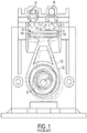
- a piston pump is a wobble piston pump ( Figure 1 ) and has the piston rod (20) attached to the piston (18) on one end and an eccentric bearing assembly (25) on the opposite end.
- piston rod (20) changes positions (as shown in the dotted lines of Figure 1 ) and causes the piston (18) to shift up and down from one side to the other (i.e., the piston "wobbles")
- the piston (18) rocks up an down from left t0 right and uses a Teflon seal or cup (14) to apply pressure to opposite sides (16A, 16B) of a chamber (17) such that one side of the chamber creates a vacuum (e.g., an inlet (10)) and one side of the chamber creates positively pressurized displacement (e.g., outlet (12)).
- a vacuum e.g., an inlet (10)
- a side of the chamber creates positively pressurized displacement (e.g., outlet (12)).
- These pumps have limited up and down travel and displacement and are good for pressure adjustment, but for volume they have a short compression stroke and displacement size per revolution.
- FIG. 2 Another kind of prior art compressor includes a rotary vane pump ( Figure 2 ). As shown by the image of a Gast® compressor in Figure 2 , the compressor includes a rotating shaft in an off center, or “eccentric” position with respect to the interior of the compressor. Piston rods (40) connect sliding vanes (42) to chambers (43), and the eccentric position of the rotary shaft provides different travel lengths for the vanes to slide inwardly and outwardly at positions about an inner circumference (45) of the compressor.
- Piston rods (40) connect sliding vanes (42) to chambers (43), and the eccentric position of the rotary shaft provides different travel lengths for the vanes to slide inwardly and outwardly at positions about an inner circumference (45) of the compressor.
- rotary vane compressors are very heavy and have a carbon dust problem and tend to wear out (vanes) quickly and must have costly machining due to close tolerances. They do move high volumes of air.
- the rotary compressor is quiet, has low vibration and is not designed for high pressure when oil-less they and wear out quickly but have a smooth non-pulsating output flow.
- JP 2000064953 specifies a pump for pumping liquid from an inlet to an outlet and providing a pressure differential between the inlet and the outlet, the pump comprising a rotating shaft, at least a pair of piston rods perpendicular to said rotating shaft, each of said piston rods connecting a corresponding piston at an end of said piston rod, said piston rods moving back and forth relative to said rotating shaft such that said each one of said pair of pistons are alternately closer to and farther from said rotating shaft, said pair of pistons moving back and forth on the same axis, a grooved plate perpendicular to said rotating shaft, said grooved plate defining a groove which is off-center with respect to said rotating shaft and a bearing extending from each of said piston rods and received in said groove such that each said bearing slides within said groove when rotational motion of the shaft rotates said grooved plate, each position of the bearing within the groove determining a corresponding position of the corresponding piston rod relative to said rotating shaft.
- US 4 443 163 or US 6 162 030 specifies a fluid displacement device in which two opposing pistons share a common rod aligned between them.
- Compressors in many industrial environments would benefit from better efficiencies in allowing for multiple pistons driven by common shafts with less duplication in parts and therefore lighter weight assemblies.
- a compressor for moving a gas from an inlet to an outlet provides a pressure differential between the inlet and the outlet as defined in Claim 1.
- Figures 3A to 3C included herein illustrate a compressor that is useful for compressing air, specific gases (e.g., oxygen compression), or even fluids.
- gases e.g., oxygen compression
- fluids is used in its broadest sense to encompass any matter that flows and can be subject to pressure, whether in gaseous or liquid form.
- the compressor may be referred to as a fluid compressor, an oxygen compressor, or an air compressor because the nature of the medium being compressed does not change the structure of the invention claimed herein.
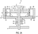
- the compressor of Figure 3A shows an overview of one embodiment of the invention.
- the compressor (50) incorporates a base end plate (70) extending across the compressor (50) and allowing a rotating shaft (60) to extend there through.
- the rotating shaft (50) is connected to a power source delivering rotational energy in standard mechanical embodiments that are not shown in the art (e.g., motors driving the rotating shaft).
- the rotating shaft (60) can rotate in either a forward or reverse direction, depending on the desired orientation for an inlet and outlet of compressed gases or fluids.
- the rotating shaft (60) extends through the compressor (50) in a vertical orientation when the base end plate (70) crosses the compressor (50) in a substantially horizontal configuration.
- the rotating shaft (60) extends from the base end plate (70) through the compressor body (52) and terminates at or near a grooved end plate (72).
- the grooved end plate (72) is characterized in part by defining a groove (58), which in one embodiment is a substantially circular groove (58).
- the circular nature of the groove (58), however, is not limiting of the invention, and the groove (58) may take any shape that affords the convenience of providing a track for guiding pistons within the compressor.
- the groove (58) may include elliptical or oblong shapes or have portions of the groove (58) that define straight segments instead of arcuate paths.
- the groove (58) in the grooved end plate (72) is configured to receive a bearing (65) that adjusts the position of associated pistons (55A, 55B) by traversing the stationary groove (58).
- the groove (58) may traverse a stationary bearing (65).
- the rotating shaft (60) may be attached to the grooved end plate (72) and impart rotational energy to the grooved end plate (72) so that the groove (58) moves about a bearing (65).
- the bearing (65) is attached to a piston rod (75) that terminates on opposite ends with respective pistons (55A, 55B).
- the pistons (55A, 55B) move back and forth within piston chambers (54A, 54B).
- the compressor (50) accommodates a sliding lateral movement by the piston rod (75), and the position is determined by the forces acting upon the bearing (65) attached to the piston rod (75).
- the piston rod (75) is a single, continuous piston rod with no breaks or interruptions along the length between the pistons (55A, 55B).
- the piston chambers (54A, 54B) are sized to provide appropriate space for the pistons to move back and forth.
- the piston rod (75) defines an opening (78) (also shown in Figures 5A and 5B ) through which the rotating shaft (60) extends; the rotating shaft (60) continues through the piston rod (75) to the grooved end plate (72).
- the rotating shaft (60) may be physically connected to either the piston rod (75) or the grooved end plate (72) and impart rotational motion to either. The rotational motion from the rotating shaft (60), applied to the piston rod (75), allows the bearing (65) to traverse the groove (58) in the grooved end plate (72).
- the grooved end plate When the rotational motion from the rotating shaft (60) is applied to grooved end plate (72), the grooved end plate actually turns so that the groove (58) actually traverses the bearing (65). Whether the rotating shaft (60) attaches and imparts rotational motion to the piston rod (75) or the grooved end plate (72), the result is that the groove (58) determines the rotational forces on the bearing (65) that in turn applies forces to the piston rod (75).
- Figure 3A shows the grooved end plate (72) turning with the bearing (65) within the “eccentric” or “off-center” groove (58).
- the term “eccentric” or “off-center” means that the center of the groove (58) is not identical with the vertical axis of the compressor or the rotating shaft (60).
- the eccentric groove (58) allows the bearing to adjust the lateral position of the piston rod (75) because as the bearing (65) traverses the groove (58), or the groove (58) slides over the bearing (65), the orientation of the groove and bearing contact pushes the associated piston rod in a lateral, or horizontal direction.
- FIG. 3A shows a network of ports (62A-62D) connecting the piston chambers with appropriate inlets (62D) and outlets (62A) within the device.
- Properly oriented valves may be utilized to ensure proper input and output flow from the piston chambers (54A, 54B), respectively.
- the network of ports may be bored into the body of the compressor (50) by known means.
- the porting (62A-62D) is normally designed into the stationary portion of the compressor (50) so that outside instruments or attachments can utilize the compressed fluid on the outlet side.
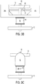
- Figures 3A-3C also show a lip seal (80) surrounding the porting section (62B, 62C) of the compressor (50).
- the seal for the porting is a lip seal (80).
- Figures 3B and 3C show the different perspectives of the compressor (50) along with the output ports for the seal (80).
- the seal body (84) is shown even more clearly in Figure 4 , which is a side cross section of the embodiment of Figure 3 .
- the seal body (84) surrounds a portion of the compressor (50) proximate the base end plate (70) and surrounds a portion of the rotating shaft (60) between the base end plate (70) and the piston rod (75).
- the ports (62A-62D) defined within the compressor body (52) match the corresponding ports (82A, 82B) of the seal.
- the embodiment of Figure 3 may also be expanded to the embodiment of Figures 5A-5D , showing that the compressor may incorporate more than one piston rod and more than one set of pistons within the same device.
- the compressor (51) includes dual piston rods (75A, 75B) which operate upon the same principles discussed above in regard to Figure 3 .
- Each piston rod (75A, 75B) includes a respective bearing (65A, 65B) that engages a single groove (58) within a grooved end plate (72).
- Each piston rod of course, terminates in opposite pistons with respective piston chambers.
- the rotating shaft (60) turns the dual piston rods (75A, 75B) simultaneously so that each traverses the same groove (58).
- piston rods (75A, 75B) are positioned such that on is on top of the other, but this embodiment is for illustration purposes only. As shown in the Figures, the piston chambers (54A - 54D) are all at equal heights, so the pistons terminating a top piston rod (75B) would be adjusted in height to fit an appropriate piston chamber that is level will all other piston chambers.
- Figure 6 shows one example of an exploded view of a compressor according to Figure 5 utilizing dual piston rods (75A, 75B).
- Figure 6 illustrates that the orientation of the components of the compressor may be adjusted for the use at hand, and in the embodiment of Figure 6 , the rotating shaft (60) fits through the eccentrically grooved end plate (72) passes through washers (91, 96A, 96B) as well as housing gasket (94).
- the head component (99) provides appropriate ports and seals for arranging the dual piston rods (75A, 75B) so that the pistons (55A-55D) move back and forth within appropriate piston chambers (54A-54D).
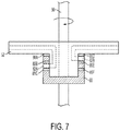
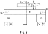
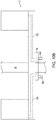
- Figures 7-10 illustrate methods of developing port networks within the body of a compressor and providing an appropriate seal therein.
- the porting may be either individualized with each piston chamber having a discrete set of input and output ports, or the porting may be combinable so that a given set of ports serves more than one piston chamber.
- Figure 7 illustrates that the compressor body (52) extends around the rotating shaft (60) and includes appropriate input and output ports (82A, 82B).
- the lip seal (80) includes proper lip seal elements (86A-86F) to ensure that peripheral equipment has access to the porting network with no loss of efficiency in terms of flow rate or pressure differential.
- Figure 8 illustrates a labyrinth seal (105A, 105B) as another option for sealing the ports (62A, 62B).
- the labyrinth seal (105) may include dual portions (105A, 105B) that fit together to allow the input and output ports to maintain maximum efficiency in operation.
- Figure 9 shows that the ports may be managed by appropriate check valves, while Figures 10A and 10B illustrate numerous locations for the ports on both the compressor body and the associated seal.
- the materials used in forming the compressor described above may include Teflon® or Rulon® piston seals or other slippery, low friction piston seals which are self-entering and floating and maintain the alignment of the piston.
- the seals may be dual facing.
- the body of the compressor, the piston rods, the pistons, and the plates within the compressor may be made of durable materials, such as low carbon steels, aluminum, and even polymeric synthetic materials. The appropriate materials can be selected for both the compressor and the associated seals to minimize or at least control thermal expansion of the components during use.
Landscapes
- Engineering & Computer Science (AREA)
- Mechanical Engineering (AREA)
- General Engineering & Computer Science (AREA)
- Compressors, Vaccum Pumps And Other Relevant Systems (AREA)
- Compressor (AREA)
- Applications Or Details Of Rotary Compressors (AREA)
Applications Claiming Priority (2)
| Application Number | Priority Date | Filing Date | Title |
|---|---|---|---|
| US201261585828P | 2012-01-12 | 2012-01-12 | |
| PCT/US2013/021394 WO2013106810A1 (en) | 2012-01-12 | 2013-01-14 | Compressor for pressurized fluid output |
Publications (3)
| Publication Number | Publication Date |
|---|---|
| EP2802779A1 EP2802779A1 (en) | 2014-11-19 |
| EP2802779A4 EP2802779A4 (en) | 2015-12-02 |
| EP2802779B1 true EP2802779B1 (en) | 2018-06-13 |
Family
ID=48781978
Family Applications (1)
| Application Number | Title | Priority Date | Filing Date |
|---|---|---|---|
| EP13736400.6A Not-in-force EP2802779B1 (en) | 2012-01-12 | 2013-01-14 | Compressor for pressurized fluid output |
Country Status (7)
Families Citing this family (4)
| Publication number | Priority date | Publication date | Assignee | Title |
|---|---|---|---|---|
| US10215166B2 (en) | 2016-12-29 | 2019-02-26 | Stuart H. Bassine | Medical air compressor |
| US11293554B2 (en) | 2017-03-09 | 2022-04-05 | Johnson Controls Technology Company | Back to back bearing sealing systems |
| US10724516B2 (en) * | 2017-06-13 | 2020-07-28 | Forum Us, Inc. | Reciprocating piston |
| CN111249772B (zh) * | 2020-02-29 | 2021-12-14 | 烟台沃尔姆真空技术有限公司 | 一种具有油水分离功能的真空泵系统 |
Family Cites Families (19)
| Publication number | Priority date | Publication date | Assignee | Title |
|---|---|---|---|---|
| GB191319203A (en) * | 1913-08-25 | 1914-08-20 | Thomas Edgar Lewis | Improvements in or relating to (Internal Combustion) Turbines. |
| US1336846A (en) * | 1915-10-08 | 1920-04-13 | Lewis Thomas Edgar | Engine |
| US1503540A (en) * | 1922-11-20 | 1924-08-05 | Au To Compressor Company | Air compressor |
| US1748443A (en) * | 1927-05-09 | 1930-02-25 | Dawson Reciprocating Crank Act | Crank mechanism |
| US3002504A (en) * | 1959-05-27 | 1961-10-03 | Clarence R Taylor | Fluid motor |
| US3216355A (en) * | 1963-02-25 | 1965-11-09 | Seeger Wanner Corp | Two-cylinder pump |
| US3300997A (en) * | 1965-08-10 | 1967-01-31 | Vilter Manufacturing Corp | Oil free refrigerant compressor |
| US3680444A (en) * | 1970-09-29 | 1972-08-01 | Leonard R Casey | Rotary kinetic device with coplaner tandem pistons |
| US4038949A (en) * | 1975-04-16 | 1977-08-02 | Farris Victor W | Rotary-radial internal combustion engine |
| DE2557811C3 (de) | 1975-12-22 | 1982-06-09 | BURDOSA Ing. Herwig Burgert, 6305 Buseck | Geradschubkurbeltrieb mit einer als Antrieb dienenden Kreuzscheibenkupplung |
| US4443163A (en) * | 1982-07-15 | 1984-04-17 | Gaither Luis A | Fluid motor or pump |
| US5076769A (en) | 1990-07-16 | 1991-12-31 | The Dow Chemical Company | Double acting pump |
| US6283723B1 (en) | 1997-01-27 | 2001-09-04 | Vairex Corporation | Integrated compressor expander apparatus |
| US6162030A (en) | 1997-06-13 | 2000-12-19 | Encynova International, Inc. | Zero leakage valveless positive fluid displacement device |
| JP2000064953A (ja) * | 1998-08-20 | 2000-03-03 | Satoshi Yamaoka | 制御ポンプ |
| DE10055445C1 (de) | 2000-11-09 | 2002-08-29 | Piotr Zontek | Kompressor mit umlaufenden Zylindern |
| GB2421981A (en) | 2005-01-07 | 2006-07-12 | David Clark | Crankless opposed-cylinder internal combustion engine with hydraulic output |
| US7475627B2 (en) * | 2005-09-27 | 2009-01-13 | Ragain Air Compressors, Inc. | Rotary to reciprocal power transfer device |
| US20070258831A1 (en) * | 2006-05-05 | 2007-11-08 | Ragain Air Compressors, Inc. | Single stage to two stage compressor |
-
2013
- 2013-01-14 US US14/370,707 patent/US11187220B2/en active Active
- 2013-01-14 ES ES13736400.6T patent/ES2684365T3/es active Active
- 2013-01-14 CA CA2859075A patent/CA2859075C/en active Active
- 2013-01-14 WO PCT/US2013/021394 patent/WO2013106810A1/en active Application Filing
- 2013-01-14 EP EP13736400.6A patent/EP2802779B1/en not_active Not-in-force
- 2013-01-14 JP JP2014552365A patent/JP6262150B2/ja not_active Expired - Fee Related
- 2013-01-14 KR KR1020147021320A patent/KR101882701B1/ko not_active Expired - Fee Related
Non-Patent Citations (1)
| Title |
|---|
| None * |
Also Published As
| Publication number | Publication date |
|---|---|
| EP2802779A4 (en) | 2015-12-02 |
| JP2015504133A (ja) | 2015-02-05 |
| WO2013106810A1 (en) | 2013-07-18 |
| CA2859075C (en) | 2020-08-11 |
| JP6262150B2 (ja) | 2018-01-17 |
| EP2802779A1 (en) | 2014-11-19 |
| KR101882701B1 (ko) | 2018-08-24 |
| KR20140135152A (ko) | 2014-11-25 |
| US20140369873A1 (en) | 2014-12-18 |
| US11187220B2 (en) | 2021-11-30 |
| CA2859075A1 (en) | 2013-07-18 |
| ES2684365T3 (es) | 2018-10-02 |
Similar Documents
| Publication | Publication Date | Title |
|---|---|---|
| US10215166B2 (en) | Medical air compressor | |
| EP2802779B1 (en) | Compressor for pressurized fluid output | |
| US8608455B2 (en) | Fluid rotary machine | |
| US20090191071A1 (en) | Compressors | |
| CN111692083A (zh) | 带有偏移滑块曲柄的电动隔膜泵 | |
| CN104074709A (zh) | 可变排量的斜盘式压缩机 | |
| CN101605993A (zh) | 往复运动压缩机和氧浓缩装置 | |
| JP6636356B2 (ja) | 極低温冷凍機 | |
| EP1536138A1 (en) | Rotor machine | |
| US12158149B2 (en) | Fluid transfer apparatus | |
| JP2019049364A (ja) | 流路切換弁 | |
| CN113677889B (zh) | 活塞式压缩机 | |
| KR102405381B1 (ko) | 회전식 유체전달장치 | |
| US20130011289A1 (en) | Improved fluid compressor and/or pump arrangement | |
| CN109519377B (zh) | 转缸活塞压缩机的泵体结构及转缸活塞压缩机 | |
| US7314354B2 (en) | Rotor machine | |
| CN108350882B (zh) | 回转式压缩机装置 | |
| KR101586473B1 (ko) | 스크롤 압축기 | |
| KR20230166387A (ko) | 정량펌프 | |
| CN118088413A (zh) | 流体机械和换热设备 | |
| JP2006037892A (ja) | 吸気排気装置用ロータリー弁型ポンプ | |
| JP2015110933A (ja) | 流体回転機 | |
| WO2017090089A1 (ja) | ロータリ式圧縮機、及びこれを搭載したヒートポンプ装置 | |
| JPH0988810A (ja) | マルチフローポンプ | |
| JP2008309026A (ja) | 流体圧縮機 |
Legal Events
| Date | Code | Title | Description |
|---|---|---|---|
| PUAI | Public reference made under article 153(3) epc to a published international application that has entered the european phase |
Free format text: ORIGINAL CODE: 0009012 |
|
| 17P | Request for examination filed |
Effective date: 20140624 |
|
| AK | Designated contracting states |
Kind code of ref document: A1 Designated state(s): AL AT BE BG CH CY CZ DE DK EE ES FI FR GB GR HR HU IE IS IT LI LT LU LV MC MK MT NL NO PL PT RO RS SE SI SK SM TR |
|
| DAX | Request for extension of the european patent (deleted) | ||
| RA4 | Supplementary search report drawn up and despatched (corrected) |
Effective date: 20151029 |
|
| RIC1 | Information provided on ipc code assigned before grant |
Ipc: F01B 3/02 20060101ALI20151023BHEP Ipc: F04B 9/10 20060101ALI20151023BHEP Ipc: F04B 49/00 20060101ALI20151023BHEP Ipc: F04B 53/14 20060101AFI20151023BHEP |
|
| GRAP | Despatch of communication of intention to grant a patent |
Free format text: ORIGINAL CODE: EPIDOSNIGR1 |
|
| STAA | Information on the status of an ep patent application or granted ep patent |
Free format text: STATUS: GRANT OF PATENT IS INTENDED |
|
| INTG | Intention to grant announced |
Effective date: 20180110 |
|
| GRAS | Grant fee paid |
Free format text: ORIGINAL CODE: EPIDOSNIGR3 |
|
| GRAA | (expected) grant |
Free format text: ORIGINAL CODE: 0009210 |
|
| STAA | Information on the status of an ep patent application or granted ep patent |
Free format text: STATUS: THE PATENT HAS BEEN GRANTED |
|
| AK | Designated contracting states |
Kind code of ref document: B1 Designated state(s): AL AT BE BG CH CY CZ DE DK EE ES FI FR GB GR HR HU IE IS IT LI LT LU LV MC MK MT NL NO PL PT RO RS SE SI SK SM TR |
|
| REG | Reference to a national code |
Ref country code: GB Ref legal event code: FG4D |
|
| REG | Reference to a national code |
Ref country code: CH Ref legal event code: EP Ref country code: AT Ref legal event code: REF Ref document number: 1008793 Country of ref document: AT Kind code of ref document: T Effective date: 20180615 |
|
| REG | Reference to a national code |
Ref country code: IE Ref legal event code: FG4D |
|
| REG | Reference to a national code |
Ref country code: DE Ref legal event code: R096 Ref document number: 602013038883 Country of ref document: DE |
|
| REG | Reference to a national code |
Ref country code: ES Ref legal event code: FG2A Ref document number: 2684365 Country of ref document: ES Kind code of ref document: T3 Effective date: 20181002 |
|
| REG | Reference to a national code |
Ref country code: NL Ref legal event code: MP Effective date: 20180613 |
|
| REG | Reference to a national code |
Ref country code: LT Ref legal event code: MG4D |
|
| PG25 | Lapsed in a contracting state [announced via postgrant information from national office to epo] |
Ref country code: SE Free format text: LAPSE BECAUSE OF FAILURE TO SUBMIT A TRANSLATION OF THE DESCRIPTION OR TO PAY THE FEE WITHIN THE PRESCRIBED TIME-LIMIT Effective date: 20180613 Ref country code: LT Free format text: LAPSE BECAUSE OF FAILURE TO SUBMIT A TRANSLATION OF THE DESCRIPTION OR TO PAY THE FEE WITHIN THE PRESCRIBED TIME-LIMIT Effective date: 20180613 Ref country code: CY Free format text: LAPSE BECAUSE OF FAILURE TO SUBMIT A TRANSLATION OF THE DESCRIPTION OR TO PAY THE FEE WITHIN THE PRESCRIBED TIME-LIMIT Effective date: 20180613 Ref country code: FI Free format text: LAPSE BECAUSE OF FAILURE TO SUBMIT A TRANSLATION OF THE DESCRIPTION OR TO PAY THE FEE WITHIN THE PRESCRIBED TIME-LIMIT Effective date: 20180613 Ref country code: BG Free format text: LAPSE BECAUSE OF FAILURE TO SUBMIT A TRANSLATION OF THE DESCRIPTION OR TO PAY THE FEE WITHIN THE PRESCRIBED TIME-LIMIT Effective date: 20180913 Ref country code: NO Free format text: LAPSE BECAUSE OF FAILURE TO SUBMIT A TRANSLATION OF THE DESCRIPTION OR TO PAY THE FEE WITHIN THE PRESCRIBED TIME-LIMIT Effective date: 20180913 |
|
| PG25 | Lapsed in a contracting state [announced via postgrant information from national office to epo] |
Ref country code: GR Free format text: LAPSE BECAUSE OF FAILURE TO SUBMIT A TRANSLATION OF THE DESCRIPTION OR TO PAY THE FEE WITHIN THE PRESCRIBED TIME-LIMIT Effective date: 20180914 Ref country code: LV Free format text: LAPSE BECAUSE OF FAILURE TO SUBMIT A TRANSLATION OF THE DESCRIPTION OR TO PAY THE FEE WITHIN THE PRESCRIBED TIME-LIMIT Effective date: 20180613 Ref country code: RS Free format text: LAPSE BECAUSE OF FAILURE TO SUBMIT A TRANSLATION OF THE DESCRIPTION OR TO PAY THE FEE WITHIN THE PRESCRIBED TIME-LIMIT Effective date: 20180613 Ref country code: HR Free format text: LAPSE BECAUSE OF FAILURE TO SUBMIT A TRANSLATION OF THE DESCRIPTION OR TO PAY THE FEE WITHIN THE PRESCRIBED TIME-LIMIT Effective date: 20180613 |
|
| REG | Reference to a national code |
Ref country code: AT Ref legal event code: MK05 Ref document number: 1008793 Country of ref document: AT Kind code of ref document: T Effective date: 20180613 |
|
| PG25 | Lapsed in a contracting state [announced via postgrant information from national office to epo] |
Ref country code: NL Free format text: LAPSE BECAUSE OF FAILURE TO SUBMIT A TRANSLATION OF THE DESCRIPTION OR TO PAY THE FEE WITHIN THE PRESCRIBED TIME-LIMIT Effective date: 20180613 |
|
| PG25 | Lapsed in a contracting state [announced via postgrant information from national office to epo] |
Ref country code: CZ Free format text: LAPSE BECAUSE OF FAILURE TO SUBMIT A TRANSLATION OF THE DESCRIPTION OR TO PAY THE FEE WITHIN THE PRESCRIBED TIME-LIMIT Effective date: 20180613 Ref country code: PL Free format text: LAPSE BECAUSE OF FAILURE TO SUBMIT A TRANSLATION OF THE DESCRIPTION OR TO PAY THE FEE WITHIN THE PRESCRIBED TIME-LIMIT Effective date: 20180613 Ref country code: SK Free format text: LAPSE BECAUSE OF FAILURE TO SUBMIT A TRANSLATION OF THE DESCRIPTION OR TO PAY THE FEE WITHIN THE PRESCRIBED TIME-LIMIT Effective date: 20180613 Ref country code: RO Free format text: LAPSE BECAUSE OF FAILURE TO SUBMIT A TRANSLATION OF THE DESCRIPTION OR TO PAY THE FEE WITHIN THE PRESCRIBED TIME-LIMIT Effective date: 20180613 Ref country code: AT Free format text: LAPSE BECAUSE OF FAILURE TO SUBMIT A TRANSLATION OF THE DESCRIPTION OR TO PAY THE FEE WITHIN THE PRESCRIBED TIME-LIMIT Effective date: 20180613 Ref country code: EE Free format text: LAPSE BECAUSE OF FAILURE TO SUBMIT A TRANSLATION OF THE DESCRIPTION OR TO PAY THE FEE WITHIN THE PRESCRIBED TIME-LIMIT Effective date: 20180613 Ref country code: IS Free format text: LAPSE BECAUSE OF FAILURE TO SUBMIT A TRANSLATION OF THE DESCRIPTION OR TO PAY THE FEE WITHIN THE PRESCRIBED TIME-LIMIT Effective date: 20181013 |
|
| PG25 | Lapsed in a contracting state [announced via postgrant information from national office to epo] |
Ref country code: SM Free format text: LAPSE BECAUSE OF FAILURE TO SUBMIT A TRANSLATION OF THE DESCRIPTION OR TO PAY THE FEE WITHIN THE PRESCRIBED TIME-LIMIT Effective date: 20180613 |
|
| REG | Reference to a national code |
Ref country code: DE Ref legal event code: R097 Ref document number: 602013038883 Country of ref document: DE |
|
| PLBE | No opposition filed within time limit |
Free format text: ORIGINAL CODE: 0009261 |
|
| STAA | Information on the status of an ep patent application or granted ep patent |
Free format text: STATUS: NO OPPOSITION FILED WITHIN TIME LIMIT |
|
| 26N | No opposition filed |
Effective date: 20190314 |
|
| PG25 | Lapsed in a contracting state [announced via postgrant information from national office to epo] |
Ref country code: SI Free format text: LAPSE BECAUSE OF FAILURE TO SUBMIT A TRANSLATION OF THE DESCRIPTION OR TO PAY THE FEE WITHIN THE PRESCRIBED TIME-LIMIT Effective date: 20180613 Ref country code: DK Free format text: LAPSE BECAUSE OF FAILURE TO SUBMIT A TRANSLATION OF THE DESCRIPTION OR TO PAY THE FEE WITHIN THE PRESCRIBED TIME-LIMIT Effective date: 20180613 |
|
| PG25 | Lapsed in a contracting state [announced via postgrant information from national office to epo] |
Ref country code: MC Free format text: LAPSE BECAUSE OF FAILURE TO SUBMIT A TRANSLATION OF THE DESCRIPTION OR TO PAY THE FEE WITHIN THE PRESCRIBED TIME-LIMIT Effective date: 20180613 |
|
| REG | Reference to a national code |
Ref country code: CH Ref legal event code: PL |
|
| PG25 | Lapsed in a contracting state [announced via postgrant information from national office to epo] |
Ref country code: LU Free format text: LAPSE BECAUSE OF NON-PAYMENT OF DUE FEES Effective date: 20190114 |
|
| REG | Reference to a national code |
Ref country code: BE Ref legal event code: MM Effective date: 20190131 |
|
| REG | Reference to a national code |
Ref country code: IE Ref legal event code: MM4A |
|
| PG25 | Lapsed in a contracting state [announced via postgrant information from national office to epo] |
Ref country code: BE Free format text: LAPSE BECAUSE OF NON-PAYMENT OF DUE FEES Effective date: 20190131 Ref country code: AL Free format text: LAPSE BECAUSE OF FAILURE TO SUBMIT A TRANSLATION OF THE DESCRIPTION OR TO PAY THE FEE WITHIN THE PRESCRIBED TIME-LIMIT Effective date: 20180613 |
|
| PG25 | Lapsed in a contracting state [announced via postgrant information from national office to epo] |
Ref country code: CH Free format text: LAPSE BECAUSE OF NON-PAYMENT OF DUE FEES Effective date: 20190131 Ref country code: LI Free format text: LAPSE BECAUSE OF NON-PAYMENT OF DUE FEES Effective date: 20190131 |
|
| PG25 | Lapsed in a contracting state [announced via postgrant information from national office to epo] |
Ref country code: IE Free format text: LAPSE BECAUSE OF NON-PAYMENT OF DUE FEES Effective date: 20190114 |
|
| PG25 | Lapsed in a contracting state [announced via postgrant information from national office to epo] |
Ref country code: TR Free format text: LAPSE BECAUSE OF FAILURE TO SUBMIT A TRANSLATION OF THE DESCRIPTION OR TO PAY THE FEE WITHIN THE PRESCRIBED TIME-LIMIT Effective date: 20180613 |
|
| PG25 | Lapsed in a contracting state [announced via postgrant information from national office to epo] |
Ref country code: PT Free format text: LAPSE BECAUSE OF FAILURE TO SUBMIT A TRANSLATION OF THE DESCRIPTION OR TO PAY THE FEE WITHIN THE PRESCRIBED TIME-LIMIT Effective date: 20181015 Ref country code: MT Free format text: LAPSE BECAUSE OF NON-PAYMENT OF DUE FEES Effective date: 20190114 |
|
| PG25 | Lapsed in a contracting state [announced via postgrant information from national office to epo] |
Ref country code: HU Free format text: LAPSE BECAUSE OF FAILURE TO SUBMIT A TRANSLATION OF THE DESCRIPTION OR TO PAY THE FEE WITHIN THE PRESCRIBED TIME-LIMIT; INVALID AB INITIO Effective date: 20130114 |
|
| PGFP | Annual fee paid to national office [announced via postgrant information from national office to epo] |
Ref country code: GB Payment date: 20211213 Year of fee payment: 10 |
|
| PGFP | Annual fee paid to national office [announced via postgrant information from national office to epo] |
Ref country code: DE Payment date: 20220112 Year of fee payment: 10 |
|
| PGFP | Annual fee paid to national office [announced via postgrant information from national office to epo] |
Ref country code: IT Payment date: 20211222 Year of fee payment: 10 Ref country code: FR Payment date: 20220116 Year of fee payment: 10 Ref country code: ES Payment date: 20220217 Year of fee payment: 10 |
|
| PG25 | Lapsed in a contracting state [announced via postgrant information from national office to epo] |
Ref country code: MK Free format text: LAPSE BECAUSE OF FAILURE TO SUBMIT A TRANSLATION OF THE DESCRIPTION OR TO PAY THE FEE WITHIN THE PRESCRIBED TIME-LIMIT Effective date: 20180613 |
|
| REG | Reference to a national code |
Ref country code: DE Ref legal event code: R119 Ref document number: 602013038883 Country of ref document: DE |
|
| GBPC | Gb: european patent ceased through non-payment of renewal fee |
Effective date: 20230114 |
|
| PG25 | Lapsed in a contracting state [announced via postgrant information from national office to epo] |
Ref country code: GB Free format text: LAPSE BECAUSE OF NON-PAYMENT OF DUE FEES Effective date: 20230114 Ref country code: DE Free format text: LAPSE BECAUSE OF NON-PAYMENT OF DUE FEES Effective date: 20230801 |
|
| PG25 | Lapsed in a contracting state [announced via postgrant information from national office to epo] |
Ref country code: FR Free format text: LAPSE BECAUSE OF NON-PAYMENT OF DUE FEES Effective date: 20230131 |
|
| PG25 | Lapsed in a contracting state [announced via postgrant information from national office to epo] |
Ref country code: IT Free format text: LAPSE BECAUSE OF NON-PAYMENT OF DUE FEES Effective date: 20230114 |
|
| REG | Reference to a national code |
Ref country code: ES Ref legal event code: FD2A Effective date: 20240327 |
|
| PG25 | Lapsed in a contracting state [announced via postgrant information from national office to epo] |
Ref country code: ES Free format text: LAPSE BECAUSE OF NON-PAYMENT OF DUE FEES Effective date: 20230115 |
|
| PG25 | Lapsed in a contracting state [announced via postgrant information from national office to epo] |
Ref country code: ES Free format text: LAPSE BECAUSE OF NON-PAYMENT OF DUE FEES Effective date: 20230115 |