EP2802438B1 - Rotierender rasierkopf mit arretierhalterung - Google Patents
Rotierender rasierkopf mit arretierhalterung Download PDFInfo
- Publication number
- EP2802438B1 EP2802438B1 EP13771615.5A EP13771615A EP2802438B1 EP 2802438 B1 EP2802438 B1 EP 2802438B1 EP 13771615 A EP13771615 A EP 13771615A EP 2802438 B1 EP2802438 B1 EP 2802438B1
- Authority
- EP
- European Patent Office
- Prior art keywords
- shaving head
- retainer
- support member
- head according
- holes
- Prior art date
- Legal status (The legal status is an assumption and is not a legal conclusion. Google has not performed a legal analysis and makes no representation as to the accuracy of the status listed.)
- Not-in-force
Links
- 210000004209 hair Anatomy 0.000 claims description 15
- 230000015572 biosynthetic process Effects 0.000 description 4
- 238000005755 formation reaction Methods 0.000 description 4
- 238000004140 cleaning Methods 0.000 description 3
- 239000000463 material Substances 0.000 description 3
- 230000008901 benefit Effects 0.000 description 2
- 238000012423 maintenance Methods 0.000 description 2
- 230000007246 mechanism Effects 0.000 description 2
- 238000012986 modification Methods 0.000 description 2
- 230000004048 modification Effects 0.000 description 2
- 230000009471 action Effects 0.000 description 1
- 230000004913 activation Effects 0.000 description 1
- 230000005540 biological transmission Effects 0.000 description 1
- 238000010276 construction Methods 0.000 description 1
- 230000008878 coupling Effects 0.000 description 1
- 238000010168 coupling process Methods 0.000 description 1
- 238000005859 coupling reaction Methods 0.000 description 1
- 230000003993 interaction Effects 0.000 description 1
- 229910052751 metal Inorganic materials 0.000 description 1
- 239000002184 metal Substances 0.000 description 1
- 150000002739 metals Chemical class 0.000 description 1
- 238000000034 method Methods 0.000 description 1
- 230000000007 visual effect Effects 0.000 description 1
Images



Classifications
-
- B—PERFORMING OPERATIONS; TRANSPORTING
- B26—HAND CUTTING TOOLS; CUTTING; SEVERING
- B26B—HAND-HELD CUTTING TOOLS NOT OTHERWISE PROVIDED FOR
- B26B19/00—Clippers or shavers operating with a plurality of cutting edges, e.g. hair clippers, dry shavers
- B26B19/14—Clippers or shavers operating with a plurality of cutting edges, e.g. hair clippers, dry shavers of the rotary-cutter type; Cutting heads therefor; Cutters therefor
- B26B19/145—Cutters being movable in the cutting head
Definitions
- the present invention relates to shaving devices of the rotary type and in particular to a rotary shaving head having at least one cutter unit and a retainer for locking the elements of the cutter unit together.
- the invention also relates to a shaver incorporating such a rotary shaving head.
- Electrical shavers are frequently used consumer items which generally comprise an assembly of moving and stationary elements that interact to cut the hairs at the surface of a user's skin.
- the shaving elements such as a cutter and cap or guard, have to be fixed to the body of the shaver.
- the shaving elements may be resiliently mounted and are generally removable for cleaning and maintenance.
- the shaving elements usually comprise an outer cap and a rotating cutter located within the cap.
- the outer cap has apertures allowing hairs to protrude therethrough and the rotary cutter has internal cutting elements that move past the apertures to cut the hairs.
- the cap and rotary cutter are held together with other components as a cutter unit and the shaver may have a number of cutter units mounted together e.g. in a bracket forming part of a head of the shaver.
- Rotary shavers with two or three cutter units are most common.
- the bracket and cutter unit or units can be removed or hinged away from the remainder of the shaver so that hair can be removed from a hair chamber located within the body or head.
- the components of the cutter units stay together.
- These components may include the cap and rotary cutter as described above but also include other parts such as springs, washers, supports and drive members required for operation of the cutter unit and its interaction with the motor which is located within the body of the shaver.
- a mechanism or retainer is usually provided to hold these components together.
- this mechanism which holds the cutter unit together will usually be associated with a single cutter unit.
- US 2007/0124936 discloses a rotary shaving head according to the preamble of claim 1.
- a rotary shaving head having at least one cutter unit, wherein each cutter unit comprises a cap, having an external surface with hair-entry openings for engaging the skin of a user; and a rotary cutter, having cutting elements supported by a carrier, the rotary cutter being locatable within and rotatable with respect to the cap,and wherein the shaving head further comprises a support member for supporting the cutter unit and a retainer, arranged to engage and lock with the support member by relative rotation therewith and retain the cap and the rotary cutter therebetween, wherein the retainer comprises an annular body defining a drive opening, the body being provided with one or more holes allowing cut hairs to pass through, and the holes are shaped as directional indicators indicating a direction of rotation of the retainer with respect to the support member.
- the retainer As a result of the proposed design, a user can identify the retainer as being a rotational component even though it is located within the support member.
- the directional indicators provide an intuitive and also tactile indication of how to open or otherwise release the retainer. In general, the indicated direction of rotation will be the direction of unlocking. Nevertheless, it will be understood that it may also indicate the direction of locking or in fact both directions.
- the retainer and support member may comprise appropriate locking elements that engage and lock against one another by rotation.
- the locking elements comprise bayonet elements having lugs on an outer circumference of the retainer which engage beneath inwardly extending flanges formed on the support member. Nevertheless, it will be understood that any other suitable rotational locking arrangement may be considered.
- the locking elements are provided with detent elements to prevent undesired loosening of the retainer during use.
- the detent elements may be in the form of snap or spring elements formed on engaging surfaces of the locking elements. Overcoming the detent will require a threshold force to be applied.
- these detents will, in general be formed on the locking elements, it will be understood that they may alternatively be provided at other locations between the retainer and support member.
- the retainer and the support member are preferably both formed of plastic material and the detents may operate by snap action due to the resiliency of the material. It will be understood that other materials may also be considered e.g. metals.
- the retainer is provided with gripping protrusions for rotating the retainer with respect to the support.
- the gripping protrusions may allow a user to grasp and turn the retainer by inserting their fingers into the cap. Alternatively, they may be engaged by a suitable tool or other object.
- the gripping protrusions preferably protrude from the surface of the retainer by at least sufficient that a force can be applied to overcome the force required to release the locking elements or detents described above.
- a height of at least 0.5 mm is desirable, preferably at least 1 mm.
- these gripping protrusions may be embodied as further directional indicators which also indicate a direction of rotation of the retainer with respect to the support member. They may thus have the shape of arrows, chevrons, triangles or the like, pointing in an intended direction of movement.
- the directional indicators provided by the shaped holes may be omitted and plain holes may be used instead, given that the gripping protrusions provide sufficient indication of the direction of rotation.
- the holes may be formed in the shape of arrows, chevrons or the like.
- arrows or chevrons should be construed in the broadest possible meaning of this term as being any form that indicates movement in the rotational direction.
- holes these holes do not necessarily need to be enclosed around their periphery and could be at least partially open to an outside or an inside of the annular body. The function of the holes is to allow hairs to pass through the retainer while retaining the necessary rigidity in order to lock against the support.
- the retainer is provided with at least three holes arranged around a circumference of the annular body.
- the holes may be identical although this need not necessarily be the case. Most preferably, four holes or more are provided.
- the annular body may comprise an inner ring which surrounds the drive opening to keep the rotary cutter in position, the one or more holes being located radially outwardly of the inner ring.
- the annular body may also have an outer ring which may engage with the support member and which can carry the locking elements. The holes may then be formed between the inner ring and the outer ring e.g. by cross-members.
- the annular body may be provided with lifting elements for assisting a user in withdrawing the retainer from the support member once unlocked.
- the lifting elements may comprise undercut portions at an outer circumference of the inner ring, assisting a user in exerting a retraction force.
- the function of the holes is to allow cut hairs and other shaving debris to pass through the retainer towards a hair collection chamber.
- the annular body is provided with tapered surfaces at a side directed towards the external surface of the cap. The tapered surfaces facilitate passage of cut hairs through the one or more holes.
- the shaving head according to the present invention may be constructed in various forms.
- the cutter unit comprises a spring-loaded spindle resiliently engaged with the carrier and passing through the drive opening when the retainer is engaged and locked with the support member.
- a spring-loaded coupling is advantageous for providing flexibility with respect to the shaver drive, in particular if a plurality of cutter units is provided which can float with respect to each other. Nevertheless, the skilled person will be aware that an engaging drive spindle on the side of the body may also be spring loaded.
- the support member is a pivotable, skin supporting rim which surrounds the cap and is mounted to pivot with respect to a housing of the shaving head during use, as generally described in WO96/02368 , the contents of which are incorporated herein by reference in their entirety.
- Such an arrangement allows the support member to better follow the skin of a user during shaving.
- the head comprises a plurality of cutter units, each supported by a respective pivotable, skin supporting rim.
- each cap support can move with respect to the housing.
- the housing may have a number of apertures formed therethrough with a support member being pivotally held within each of the apertures. Nevertheless, it will be understood that a plurality of cutter units may be mounted together without relative movement.
- the support members of each cutter unit may be integrally formed together as part of the housing.
- the support member may form part of a first housing part of the shaving head which can be moved or pivoted relative to a second housing part of the shaving head into an open position allowing access to the retainer for unlocking the retainer from the support member.
- a first housing part is sometimes referred to as a bracket assembly.
- the invention also relates to a shaver comprising a main body and a shaving head as described above.
- a shaver comprising a main body and a shaving head as described above.
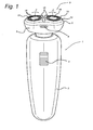
- FIG. 1 shows a perspective view of a shaver 1 according to the invention.
- the shaver 1 has a main body 2 and a head 3.
- the body 2 are housed motor, transmission, power supply, control electronics and the like which are otherwise conventional and will not be described further.
- a switch 4 for activation of the shaver is provided on the front of the body 2.
- the head 3 comprises a first housing part 5 and a second housing part 6 on which are mounted a pair of cutter units 10.
- Each cutter unit 10 comprises a support member 12 which has an opening 14 through which a cap 16 protrudes.
- the support members 12 are mounted to float with respect to the second housing part 6, whereby they pivot about a transverse axis Z.
- the cap 16 has slots 18 formed through its external surface 20 as is generally conventional.
- the second housing part 6 is connected to the first housing part 5 and can be released by a catch 8 which allows access to the rear side of the cutter units 10
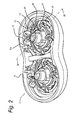
- FIG 2 shows in perspective view, the underside of the second housing part 6 of Figure 1 , detached from the body 2 of the shaver 1.
- each cutter unit 10 comprises a rotary cutter 24 having a carrier 26 and a spindle 28.
- a retainer 30 overlies the rotary cutter 24 and holds it in engagement with the support member 12.
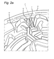
- Figure 2a shows a detail of Figure 2 illustrating the manner in which the support member 12 is held together with the second housing part 6.
- Trunnions 7 are formed at diametrically opposite sides of the second housing part 6 aligned with the axis Z.
- Clips 13 provided on the support member 12 engage the trunnions 7 to form a pivoting connection.
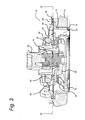
- FIG 3 shows a cross-section through the cutter unit 10 of Figure 2 along line III-III.
- Cap 16 protrudes through opening 14 in support member 12 such that its external surface 20 extends slightly beyond the support member 12.
- the rotary cutter 24 has cutting elements 32 supported by carrier 26.
- the cutting elements 32 engage against the cap 16 under the force of a spring 34 which is mounted between the carrier 26 and the spindle 28.
- the retainer 30 comprises an inner ring 36 and an outer ring 38 with holes 40 formed between them.
- the inner ring 36 defines a drive opening 42 through which the spindle 28 extends.
- the outer ring 38 carries lugs 44 at its outer circumference, which engage beneath inwardly extending flanges 46 formed on the support 12.
- Lugs 44 and flanges 46 act as locking elements forming a bayonet connection between the retainer 30 and support member 12.
- a lower surface of the inner ring 36 directed towards the external surface 20 of the cap 16 is provided with tapered surfaces 35. In use, the tapered surfaces 35 facilitate passage of cut hairs and shaving debris through the holes 40.
- Figure 4 shows the retainer 30 of Figure 3 in perspective view illustrating the inner ring 36, the outer ring 38, the drive opening 42, the holes 40 and the lugs 44.
- the inner ring 36 and the outer ring 38 are joined to each other by cross-members 50 whereby the retainer 30 defines a generally annular body 48 surrounding the drive opening 42.
- Formed on the cross-members 50 are gripping protrusions 52 having the form of chevrons.
- a tip 54 of the chevron shaped protrusion 52 points in an anti-clockwise direction when viewed from above.
- Each hole 40 has the shape of an arrow with a tip 56 of each arrow shape pointing in the same anti-clockwise direction as the tips 54 of the chevrons.
- Figure 5 shows a horizontal cross-sectional view from below through the cutter unit of Figure 3 along line V-V illustrating the manner in which the bayonet connection is formed between retainer 30 and support member 12.
- Lugs 44 formed on outer ring 38 are shown engaged with abutments 58 on the support member 12, which limit the degree of relative rotation of these two components.
- detents 60 are also shown on the support member 12 at the point of engagement with the lugs 44. It will be noted in this view that only four lugs are shown engaging with four abutments.
- the lugs 44 disengage from beneath the flanges 46 and the retainer 30 can be retracted from the support member 12.
- the rotary cutter 24 can also be removed and cleaned or replaced, as can be the cap 16. Re-assembly takes place in the same way by reversing the above sequence.
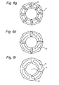
- Figures 6a to 6i represent a number of alternative designs for the retainer 30.
- the directional formations are provided by the holes 40 only.
- the gripping protrusions 52 are formed as directional formations and the holes 40 are generally rectangular.
- no gripping protrusions are present.
- the number of holes 40 is greater than in the other devices.
- the holes 40 extend through the outer ring 38, which is discontinuous.
- the holes 40 extend through the inner ring 36 which is discontinuous.
- Figure 6i represents a particular example where the drive opening 42 is provided with directional formations 68.
- Figure 7 shows a retainer 130 according to a second embodiment of the invention.
- the inner ring 136 is provided with lifting elements 164.
- the lifting elements 164 are formed as partial undercut portions at an outer circumference of the inner ring 136. Operation of the retainer 130 of Figure 7 is substantially the same as that of Figure 4 . On release of the retainer from the support member, a user's fingers can engage beneath the lifting elements in order to better withdraw the retainer 130 from the support member.
Landscapes
- Life Sciences & Earth Sciences (AREA)
- Forests & Forestry (AREA)
- Engineering & Computer Science (AREA)
- Mechanical Engineering (AREA)
- Dry Shavers And Clippers (AREA)
Claims (16)
- Rotierender Scherkopf (3) mit mindestens einer Schneideeinheit (10), wobei jede Schneideeinheit umfasst:eine Kappe (16), die eine Außenoberfläche (20) mit Haareintrittsöffnungen (18) aufweist, um in die Haut eines Benutzers einzugreifen; sowieein rotierendes Messer (24), das von einem Träger (26) getragene Schneidelemente (32) aufweist, wobei das rotierende Messer innerhalb der Kappe positionierbar und dieser gegenüber rotierbar ist;und wobei der Scherkopf weiterhin umfasst:ein Auflageelement (12), um die Schneideeinheit zu tragen; sowieeine Halterung (30), die so angeordnet ist, dass sie mit dem Auflageelement in Eingriff kommt und durch relative Rotation mit diesem verrastet und die Kappe sowie das rotierende Messer dazwischen festhält, wobei die Halterung einen eine Antriebsöffnung (42) definierenden ringförmigen Körper (48) umfasst, dadurch gekennzeichnet, dass der ringförmige Körper mit einem oder mehreren Löchern (40) versehen ist, durch die geschnittene Haare passieren können, wobei die Löcher als eine Rotationsrichtung der Halterung gegenüber dem Auflageelement zeigende Richtungsindikatoren geformt sind.
- Scherkopf nach Anspruch 1, wobei die Halterung und das Auflageelement Arretierelemente umfassen, die miteinander Eingriff kommen und durch Drehung gegeneinander verrasten.
- Scherkopf nach Anspruch 2, wobei die Arretierelemente Bajonettelemente umfassen, welche Ansätze auf einem äußeren Umfang der Halterung aufweisen, die unterhalb sich nach innen erstreckenden, auf dem Auflageelement ausgebildeten Flanschen eingreifen.
- Scherkopf nach Anspruch 2 oder Anspruch 3, wobei die Arretierelemente mit Rastelementen versehen sind.
- Scherkopf nach einem der vorangegangenen Ansprüche, wobei die Halterung mit Greifvorsprüngen versehen ist, um die Halterung gegenüber dem Auflageelement zu drehen.
- Scherkopf nach Anspruch 5, wobei die Greifvorsprünge als weitere Richtungsindikatoren ausgebildet sind, die ebenfalls eine Rotationsrichtung der Halterung gegenüber dem Auflageelement zeigen.
- Scherkopf nach einem der vorangegangenen Ansprüche, wobei die Löcher in Form von Pfeilen oder Chevrons ausgebildet sind.
- Scherkopf nach einem der vorangegangenen Ansprüche mit mindestens drei, um einen Umfang des ringförmigen Körpers angeordneten Löchern.
- Scherkopf nach einem der vorangegangenen Ansprüche, wobei der ringförmige Körper einen äußeren Ring und einen inneren Ring umfasst, der die Antriebsöffnung umgibt, wobei das eine oder mehrere Löcher von dem inneren Ring zwischen dem äußeren Ring und dem inneren Ring radial nach außen angeordnet sind.
- Scherkopf nach Anspruch 9, wobei der ringförmige Körper mit Hubelementen versehen ist, um einem Benutzer zu helfen, die Halterung nach Entriegelung aus dem Auflageelement herauszuziehen, wobei die Hubelemente an einem äußeren Umfang der inneren Rings hinterschnittene Teile umfassen.
- Scherkopf nach einem der vorangegangenen Ansprüche, wobei der ringförmige Körper auf einer zu der Außenoberfläche der Kappe hin gerichteten Seite mit sich verjüngenden Oberflächen versehen ist, wobei die sich verjüngenden Oberflächen den Durchgang des geschnittenen Haares durch das eine oder mehrere Löcher erleichtern.
- Scherkopf nach einem der vorangegangenen Ansprüche, wobei das rotierende Messer eine federbelastete Antriebsspindel umfasst, die mit dem Träger federnd im Eingriff ist und durch die Antriebsöffnung hindurchgeht, wenn die Halterung mit dem Auflageelement in Eingriff kommt und mit diesem verrastet.
- Scherkopf nach einem der vorangegangenen Ansprüche, wobei das Auflageelement ein schwenkbarer, die Haut stützender Kranz ist, der die Kappe umgibt und so angebracht ist, dass er bei Gebrauch gegenüber einem Gehäuse des Scherkopfes schwenkt.
- Scherkopf nach Anspruch 13 mit mehreren Schneideeinheiten, die jeweils von einem entsprechenden schwenkbaren, die Haut stützenden Kranz getragen werden.
- Scherkopf nach einem der vorangegangenen Ansprüche, wobei das Auflageelement einen Teil eines ersten Gehäuseteils des Scherkopfes bildet, der relativ zu einem zweiten Gehäuseteil des Scherkopfes in eine offene Position bewegt oder geschwenkt werden kann, wodurch der Halterung ein Zugang ermöglicht wird und diese aus dem Auflageelement entarretiert werden kann.
- Rasierapparat mit einem Hauptkörper und einem Scherkopf nach einem der vorangegangenen Ansprüche.
Applications Claiming Priority (2)
| Application Number | Priority Date | Filing Date | Title |
|---|---|---|---|
| US201261679098P | 2012-08-03 | 2012-08-03 | |
| PCT/IB2013/056093 WO2014020500A1 (en) | 2012-08-03 | 2013-07-25 | Rotary shaving head having a locking retainer |
Publications (2)
| Publication Number | Publication Date |
|---|---|
| EP2802438A1 EP2802438A1 (de) | 2014-11-19 |
| EP2802438B1 true EP2802438B1 (de) | 2015-06-17 |
Family
ID=49301561
Family Applications (1)
| Application Number | Title | Priority Date | Filing Date |
|---|---|---|---|
| EP13771615.5A Not-in-force EP2802438B1 (de) | 2012-08-03 | 2013-07-25 | Rotierender rasierkopf mit arretierhalterung |
Country Status (6)
| Country | Link |
|---|---|
| US (1) | US20150224654A1 (de) |
| EP (1) | EP2802438B1 (de) |
| JP (1) | JP5782578B2 (de) |
| CN (1) | CN104159713B (de) |
| RU (1) | RU2014139693A (de) |
| WO (1) | WO2014020500A1 (de) |
Families Citing this family (17)
| Publication number | Priority date | Publication date | Assignee | Title |
|---|---|---|---|---|
| WO2010103425A1 (en) * | 2009-03-09 | 2010-09-16 | Koninklijke Philips Electronics N.V. | Shaving device with improved contour following |
| EP2964429B1 (de) * | 2013-05-16 | 2016-08-24 | Koninklijke Philips N.V. | Rasierkopf mit schwenkbarer rasiereinheit |
| JP6688049B2 (ja) * | 2015-11-24 | 2020-04-28 | マクセルイズミ株式会社 | ロータリー式電気かみそりおよびロータリー式電気かみそりの内刃の製造方法 |
| RU2732393C1 (ru) * | 2017-01-27 | 2020-09-16 | Конинклейке Филипс Н.В. | Бритвенный блок, содержащий режущие блоки с промывочным отверстием для очистки камеры для сбора волос |
| AU201715869S (en) * | 2017-03-31 | 2017-10-19 | Koninklijke Philips Nv | Shaver |
| AU201715925S (en) * | 2017-03-31 | 2017-10-23 | Koninklijke Philips Nv | Shaver |
| CN107379031B (zh) * | 2017-07-25 | 2023-03-21 | 深圳素士科技股份有限公司 | 内刀固定结构以及具有该结构的剃须刀 |
| EP3486047A1 (de) | 2017-11-21 | 2019-05-22 | Koninklijke Philips N.V. | Haarschneideeinheit mit einer kopplungsstruktur |
| CN109807948B (zh) * | 2017-11-21 | 2023-04-14 | 皇家飞利浦有限公司 | 具有保持结构的剃刮单元 |
| EP3732005B1 (de) * | 2017-11-21 | 2022-03-23 | Koninklijke Philips N.V. | Rasiereinheit mit einer haltestruktur |
| EP3488981A1 (de) * | 2017-11-22 | 2019-05-29 | Koninklijke Philips N.V. | Rasiereinheit mit einer haltestruktur |
| WO2020019242A1 (zh) * | 2018-07-26 | 2020-01-30 | 舒可士(深圳)科技有限公司 | 联接结构及剃须装置 |
| WO2020030642A1 (en) * | 2018-08-07 | 2020-02-13 | Koninklijke Philips N.V. | Hair cutting appliance |
| EP3626415A1 (de) * | 2018-09-21 | 2020-03-25 | Koninklijke Philips N.V. | Verbesserte haarschneideeinheit für einen rasierapparat |
| USD845545S1 (en) | 2018-08-21 | 2019-04-09 | E. Mishan & Sons, Inc. | Rotary shaver |
| EP3647001A1 (de) * | 2018-11-05 | 2020-05-06 | Koninklijke Philips N.V. | Rasierapparat mit verbesserter kappenfunktionalität |
| CN109877884B (zh) * | 2019-01-30 | 2024-05-07 | 浙江超人科技股份有限公司 | 一种剃毛装置的剃刀头 |
Family Cites Families (18)
| Publication number | Priority date | Publication date | Assignee | Title |
|---|---|---|---|---|
| BE526029A (de) * | 1953-10-01 | |||
| CH363588A (fr) * | 1960-04-13 | 1962-07-31 | Affolter Andre | Tête de rasoir mécanique |
| US3019525A (en) * | 1960-06-29 | 1962-02-06 | Bruecker John | Shear plate and cutter assembly for rotary type dry shaver |
| US4648630A (en) * | 1983-02-16 | 1987-03-10 | David A. Zornes | Fire hose coupling lock |
| US5625950A (en) | 1994-07-19 | 1997-05-06 | U.S. Philips Corporation | Shaving apparatus |
| US6158323A (en) * | 1998-10-15 | 2000-12-12 | Tenryu Seikyo Kabushiki Kaisha | Disk cutter |
| JP3896506B2 (ja) * | 2000-07-06 | 2007-03-22 | 貞三 佐藤 | 電気剃刀 |
| US20040201215A1 (en) * | 2003-04-10 | 2004-10-14 | Steingass Robert W. | Safety lock for a hose coupling |
| WO2006067721A1 (en) * | 2004-12-22 | 2006-06-29 | Koninklijke Philips Electronics N.V. | Shaving apparatus |
| US7210474B2 (en) * | 2005-03-23 | 2007-05-01 | Saint-Gobain Abrasives Technology Company | Saw blade with cutting depth gauge |
| JP4756908B2 (ja) * | 2005-05-18 | 2011-08-24 | 株式会社泉精器製作所 | ロータリー式電気かみそり |
| JP2007151925A (ja) * | 2005-12-07 | 2007-06-21 | Izumi Products Co | ロータリー式電気かみそり |
| CN201179659Y (zh) * | 2008-04-25 | 2009-01-14 | 曹伟明 | 多环剃须刀组 |
| JP5339338B2 (ja) * | 2008-06-27 | 2013-11-13 | 株式会社泉精器製作所 | 回転式電気かみそり |
| JP5207457B2 (ja) | 2008-06-27 | 2013-06-12 | 株式会社泉精器製作所 | 回転式電気かみそり |
| US9027251B2 (en) * | 2009-04-29 | 2015-05-12 | Spectrum Brands, Inc. | Rotary electric shaver |
| JP5473462B2 (ja) * | 2009-08-06 | 2014-04-16 | 株式会社泉精器製作所 | ロータリー式電気かみそり |
| JP6034193B2 (ja) * | 2009-11-09 | 2016-11-30 | コーニンクレッカ フィリップス エヌ ヴェKoninklijke Philips N.V. | シェービングヘッドユニット及び斯かるシェービングヘッドユニットを備えたシェーバ |
-
2013
- 2013-07-25 EP EP13771615.5A patent/EP2802438B1/de not_active Not-in-force
- 2013-07-25 CN CN201380012286.9A patent/CN104159713B/zh active Active
- 2013-07-25 JP JP2015505066A patent/JP5782578B2/ja not_active Expired - Fee Related
- 2013-07-25 RU RU2014139693A patent/RU2014139693A/ru not_active Application Discontinuation
- 2013-07-25 US US14/418,823 patent/US20150224654A1/en not_active Abandoned
- 2013-07-25 WO PCT/IB2013/056093 patent/WO2014020500A1/en not_active Ceased
Also Published As
| Publication number | Publication date |
|---|---|
| CN104159713A (zh) | 2014-11-19 |
| JP5782578B2 (ja) | 2015-09-24 |
| US20150224654A1 (en) | 2015-08-13 |
| RU2014139693A (ru) | 2016-09-27 |
| CN104159713B (zh) | 2016-01-20 |
| JP2015516205A (ja) | 2015-06-11 |
| WO2014020500A1 (en) | 2014-02-06 |
| EP2802438A1 (de) | 2014-11-19 |
Similar Documents
| Publication | Publication Date | Title |
|---|---|---|
| US20150224654A1 (en) | Rotary shaving head having a locking retainer | |
| US7487592B2 (en) | Electric rotary shaver | |
| EP2943319B1 (de) | Elektrischer rotationsrasierapparat | |
| EP2246159B1 (de) | Elektrischer Rotationsrasierapparat | |
| JP5215301B2 (ja) | 切除される毛を収集するための空間を有するシェーバ | |
| EP2138284B1 (de) | Elektrischer Rotationsrasierapparat | |
| EP1637293B1 (de) | Elektrischer Rotations-Rasierapparat | |
| EP2213427B1 (de) | Klingeneinheit für elektrischen Rasierapparat | |
| EP2368674A1 (de) | Nasenhaar-Schneidegerät | |
| US20120023753A1 (en) | knife having a locking mechanism | |
| CA2644993A1 (en) | Food product slicer knife and associated slicer and knife removal tool | |
| CN102946710A (zh) | 使用切割刀片的旋转切割头和包括这种切割头的切割设备 | |
| EP3002093B1 (de) | Elektrischer rotationsrasierapparat | |
| RU2005105195A (ru) | Режущее устройство | |
| CN104661512A (zh) | 用于旋转式割草机的切割头、适于安装至该切割头的切割元件以及包括该切割头的旋转式割草机 | |
| EP3651948A1 (de) | Haarführung für haarschneidevorrichtung | |
| WO2006118898A1 (en) | Protective cover | |
| JP2005333871A (ja) | 保護カバー及び刈払機 | |
| EP4197724A1 (de) | Rasierklingenaufsätze | |
| JP6143328B2 (ja) | 線状カッターの取付構造及びこれを備えた刈払機の接地体 | |
| JP5276495B2 (ja) | バリカンの櫛アタッチメント | |
| CN217967122U (zh) | 一种剃须刀的头部固定结构及剃须刀 | |
| JP2006304646A (ja) | 草刈機における絡み防止構造 | |
| JP4513703B2 (ja) | 排水栓用ケレップ軸構造 | |
| HK1084917A (en) | Electric rotary shaver |
Legal Events
| Date | Code | Title | Description |
|---|---|---|---|
| PUAI | Public reference made under article 153(3) epc to a published international application that has entered the european phase |
Free format text: ORIGINAL CODE: 0009012 |
|
| 17P | Request for examination filed |
Effective date: 20140814 |
|
| AK | Designated contracting states |
Kind code of ref document: A1 Designated state(s): AL AT BE BG CH CY CZ DE DK EE ES FI FR GB GR HR HU IE IS IT LI LT LU LV MC MK MT NL NO PL PT RO RS SE SI SK SM TR |
|
| GRAP | Despatch of communication of intention to grant a patent |
Free format text: ORIGINAL CODE: EPIDOSNIGR1 |
|
| DAX | Request for extension of the european patent (deleted) | ||
| INTG | Intention to grant announced |
Effective date: 20150129 |
|
| GRAS | Grant fee paid |
Free format text: ORIGINAL CODE: EPIDOSNIGR3 |
|
| GRAA | (expected) grant |
Free format text: ORIGINAL CODE: 0009210 |
|
| AK | Designated contracting states |
Kind code of ref document: B1 Designated state(s): AL AT BE BG CH CY CZ DE DK EE ES FI FR GB GR HR HU IE IS IT LI LT LU LV MC MK MT NL NO PL PT RO RS SE SI SK SM TR |
|
| REG | Reference to a national code |
Ref country code: GB Ref legal event code: FG4D |
|
| REG | Reference to a national code |
Ref country code: CH Ref legal event code: EP |
|
| REG | Reference to a national code |
Ref country code: AT Ref legal event code: REF Ref document number: 731643 Country of ref document: AT Kind code of ref document: T Effective date: 20150715 |
|
| REG | Reference to a national code |
Ref country code: IE Ref legal event code: FG4D |
|
| REG | Reference to a national code |
Ref country code: DE Ref legal event code: R096 Ref document number: 602013002049 Country of ref document: DE |
|
| PG25 | Lapsed in a contracting state [announced via postgrant information from national office to epo] |
Ref country code: FI Free format text: LAPSE BECAUSE OF FAILURE TO SUBMIT A TRANSLATION OF THE DESCRIPTION OR TO PAY THE FEE WITHIN THE PRESCRIBED TIME-LIMIT Effective date: 20150617 Ref country code: HR Free format text: LAPSE BECAUSE OF FAILURE TO SUBMIT A TRANSLATION OF THE DESCRIPTION OR TO PAY THE FEE WITHIN THE PRESCRIBED TIME-LIMIT Effective date: 20150617 Ref country code: LT Free format text: LAPSE BECAUSE OF FAILURE TO SUBMIT A TRANSLATION OF THE DESCRIPTION OR TO PAY THE FEE WITHIN THE PRESCRIBED TIME-LIMIT Effective date: 20150617 Ref country code: NO Free format text: LAPSE BECAUSE OF FAILURE TO SUBMIT A TRANSLATION OF THE DESCRIPTION OR TO PAY THE FEE WITHIN THE PRESCRIBED TIME-LIMIT Effective date: 20150917 |
|
| REG | Reference to a national code |
Ref country code: AT Ref legal event code: MK05 Ref document number: 731643 Country of ref document: AT Kind code of ref document: T Effective date: 20150617 |
|
| REG | Reference to a national code |
Ref country code: LT Ref legal event code: MG4D Ref country code: NL Ref legal event code: MP Effective date: 20150617 |
|
| PG25 | Lapsed in a contracting state [announced via postgrant information from national office to epo] |
Ref country code: RS Free format text: LAPSE BECAUSE OF FAILURE TO SUBMIT A TRANSLATION OF THE DESCRIPTION OR TO PAY THE FEE WITHIN THE PRESCRIBED TIME-LIMIT Effective date: 20150617 Ref country code: GR Free format text: LAPSE BECAUSE OF FAILURE TO SUBMIT A TRANSLATION OF THE DESCRIPTION OR TO PAY THE FEE WITHIN THE PRESCRIBED TIME-LIMIT Effective date: 20150918 Ref country code: BG Free format text: LAPSE BECAUSE OF FAILURE TO SUBMIT A TRANSLATION OF THE DESCRIPTION OR TO PAY THE FEE WITHIN THE PRESCRIBED TIME-LIMIT Effective date: 20150917 Ref country code: LV Free format text: LAPSE BECAUSE OF FAILURE TO SUBMIT A TRANSLATION OF THE DESCRIPTION OR TO PAY THE FEE WITHIN THE PRESCRIBED TIME-LIMIT Effective date: 20150617 |
|
| PG25 | Lapsed in a contracting state [announced via postgrant information from national office to epo] |
Ref country code: EE Free format text: LAPSE BECAUSE OF FAILURE TO SUBMIT A TRANSLATION OF THE DESCRIPTION OR TO PAY THE FEE WITHIN THE PRESCRIBED TIME-LIMIT Effective date: 20150617 |
|
| PGFP | Annual fee paid to national office [announced via postgrant information from national office to epo] |
Ref country code: DE Payment date: 20150930 Year of fee payment: 3 |
|
| PG25 | Lapsed in a contracting state [announced via postgrant information from national office to epo] |
Ref country code: PT Free format text: LAPSE BECAUSE OF FAILURE TO SUBMIT A TRANSLATION OF THE DESCRIPTION OR TO PAY THE FEE WITHIN THE PRESCRIBED TIME-LIMIT Effective date: 20151019 Ref country code: AT Free format text: LAPSE BECAUSE OF FAILURE TO SUBMIT A TRANSLATION OF THE DESCRIPTION OR TO PAY THE FEE WITHIN THE PRESCRIBED TIME-LIMIT Effective date: 20150617 Ref country code: RO Free format text: LAPSE BECAUSE OF NON-PAYMENT OF DUE FEES Effective date: 20150617 Ref country code: PL Free format text: LAPSE BECAUSE OF FAILURE TO SUBMIT A TRANSLATION OF THE DESCRIPTION OR TO PAY THE FEE WITHIN THE PRESCRIBED TIME-LIMIT Effective date: 20150617 Ref country code: CZ Free format text: LAPSE BECAUSE OF FAILURE TO SUBMIT A TRANSLATION OF THE DESCRIPTION OR TO PAY THE FEE WITHIN THE PRESCRIBED TIME-LIMIT Effective date: 20150617 Ref country code: SK Free format text: LAPSE BECAUSE OF FAILURE TO SUBMIT A TRANSLATION OF THE DESCRIPTION OR TO PAY THE FEE WITHIN THE PRESCRIBED TIME-LIMIT Effective date: 20150617 Ref country code: IS Free format text: LAPSE BECAUSE OF FAILURE TO SUBMIT A TRANSLATION OF THE DESCRIPTION OR TO PAY THE FEE WITHIN THE PRESCRIBED TIME-LIMIT Effective date: 20151017 Ref country code: ES Free format text: LAPSE BECAUSE OF FAILURE TO SUBMIT A TRANSLATION OF THE DESCRIPTION OR TO PAY THE FEE WITHIN THE PRESCRIBED TIME-LIMIT Effective date: 20150617 |
|
| REG | Reference to a national code |
Ref country code: DE Ref legal event code: R097 Ref document number: 602013002049 Country of ref document: DE |
|
| PG25 | Lapsed in a contracting state [announced via postgrant information from national office to epo] |
Ref country code: MC Free format text: LAPSE BECAUSE OF FAILURE TO SUBMIT A TRANSLATION OF THE DESCRIPTION OR TO PAY THE FEE WITHIN THE PRESCRIBED TIME-LIMIT Effective date: 20150617 |
|
| REG | Reference to a national code |
Ref country code: IE Ref legal event code: MM4A |
|
| PLBE | No opposition filed within time limit |
Free format text: ORIGINAL CODE: 0009261 |
|
| STAA | Information on the status of an ep patent application or granted ep patent |
Free format text: STATUS: NO OPPOSITION FILED WITHIN TIME LIMIT |
|
| PG25 | Lapsed in a contracting state [announced via postgrant information from national office to epo] |
Ref country code: DK Free format text: LAPSE BECAUSE OF FAILURE TO SUBMIT A TRANSLATION OF THE DESCRIPTION OR TO PAY THE FEE WITHIN THE PRESCRIBED TIME-LIMIT Effective date: 20150617 Ref country code: IT Free format text: LAPSE BECAUSE OF FAILURE TO SUBMIT A TRANSLATION OF THE DESCRIPTION OR TO PAY THE FEE WITHIN THE PRESCRIBED TIME-LIMIT Effective date: 20150617 |
|
| 26N | No opposition filed |
Effective date: 20160318 |
|
| REG | Reference to a national code |
Ref country code: FR Ref legal event code: PLFP Year of fee payment: 4 |
|
| PG25 | Lapsed in a contracting state [announced via postgrant information from national office to epo] |
Ref country code: IE Free format text: LAPSE BECAUSE OF NON-PAYMENT OF DUE FEES Effective date: 20150725 |
|
| PG25 | Lapsed in a contracting state [announced via postgrant information from national office to epo] |
Ref country code: SI Free format text: LAPSE BECAUSE OF FAILURE TO SUBMIT A TRANSLATION OF THE DESCRIPTION OR TO PAY THE FEE WITHIN THE PRESCRIBED TIME-LIMIT Effective date: 20150617 |
|
| PGFP | Annual fee paid to national office [announced via postgrant information from national office to epo] |
Ref country code: FR Payment date: 20160728 Year of fee payment: 4 |
|
| PG25 | Lapsed in a contracting state [announced via postgrant information from national office to epo] |
Ref country code: BE Free format text: LAPSE BECAUSE OF FAILURE TO SUBMIT A TRANSLATION OF THE DESCRIPTION OR TO PAY THE FEE WITHIN THE PRESCRIBED TIME-LIMIT Effective date: 20150617 |
|
| PGFP | Annual fee paid to national office [announced via postgrant information from national office to epo] |
Ref country code: TR Payment date: 20160719 Year of fee payment: 4 |
|
| REG | Reference to a national code |
Ref country code: DE Ref legal event code: R119 Ref document number: 602013002049 Country of ref document: DE |
|
| REG | Reference to a national code |
Ref country code: CH Ref legal event code: PL |
|
| PG25 | Lapsed in a contracting state [announced via postgrant information from national office to epo] |
Ref country code: MT Free format text: LAPSE BECAUSE OF FAILURE TO SUBMIT A TRANSLATION OF THE DESCRIPTION OR TO PAY THE FEE WITHIN THE PRESCRIBED TIME-LIMIT Effective date: 20150617 |
|
| PG25 | Lapsed in a contracting state [announced via postgrant information from national office to epo] |
Ref country code: LI Free format text: LAPSE BECAUSE OF NON-PAYMENT OF DUE FEES Effective date: 20160731 Ref country code: DE Free format text: LAPSE BECAUSE OF NON-PAYMENT OF DUE FEES Effective date: 20170201 Ref country code: CH Free format text: LAPSE BECAUSE OF NON-PAYMENT OF DUE FEES Effective date: 20160731 |
|
| PG25 | Lapsed in a contracting state [announced via postgrant information from national office to epo] |
Ref country code: HU Free format text: LAPSE BECAUSE OF FAILURE TO SUBMIT A TRANSLATION OF THE DESCRIPTION OR TO PAY THE FEE WITHIN THE PRESCRIBED TIME-LIMIT; INVALID AB INITIO Effective date: 20130725 |
|
| PG25 | Lapsed in a contracting state [announced via postgrant information from national office to epo] |
Ref country code: CY Free format text: LAPSE BECAUSE OF FAILURE TO SUBMIT A TRANSLATION OF THE DESCRIPTION OR TO PAY THE FEE WITHIN THE PRESCRIBED TIME-LIMIT Effective date: 20150617 Ref country code: SE Free format text: LAPSE BECAUSE OF FAILURE TO SUBMIT A TRANSLATION OF THE DESCRIPTION OR TO PAY THE FEE WITHIN THE PRESCRIBED TIME-LIMIT Effective date: 20150617 Ref country code: NL Free format text: LAPSE BECAUSE OF FAILURE TO SUBMIT A TRANSLATION OF THE DESCRIPTION OR TO PAY THE FEE WITHIN THE PRESCRIBED TIME-LIMIT Effective date: 20150617 |
|
| PG25 | Lapsed in a contracting state [announced via postgrant information from national office to epo] |
Ref country code: LU Free format text: LAPSE BECAUSE OF NON-PAYMENT OF DUE FEES Effective date: 20150725 |
|
| GBPC | Gb: european patent ceased through non-payment of renewal fee |
Effective date: 20170725 |
|
| REG | Reference to a national code |
Ref country code: FR Ref legal event code: ST Effective date: 20180330 |
|
| PG25 | Lapsed in a contracting state [announced via postgrant information from national office to epo] |
Ref country code: GB Free format text: LAPSE BECAUSE OF NON-PAYMENT OF DUE FEES Effective date: 20170725 |
|
| PG25 | Lapsed in a contracting state [announced via postgrant information from national office to epo] |
Ref country code: SM Free format text: LAPSE BECAUSE OF FAILURE TO SUBMIT A TRANSLATION OF THE DESCRIPTION OR TO PAY THE FEE WITHIN THE PRESCRIBED TIME-LIMIT Effective date: 20150617 Ref country code: FR Free format text: LAPSE BECAUSE OF NON-PAYMENT OF DUE FEES Effective date: 20170731 |
|
| PG25 | Lapsed in a contracting state [announced via postgrant information from national office to epo] |
Ref country code: MK Free format text: LAPSE BECAUSE OF FAILURE TO SUBMIT A TRANSLATION OF THE DESCRIPTION OR TO PAY THE FEE WITHIN THE PRESCRIBED TIME-LIMIT Effective date: 20150617 |
|
| PG25 | Lapsed in a contracting state [announced via postgrant information from national office to epo] |
Ref country code: AL Free format text: LAPSE BECAUSE OF FAILURE TO SUBMIT A TRANSLATION OF THE DESCRIPTION OR TO PAY THE FEE WITHIN THE PRESCRIBED TIME-LIMIT Effective date: 20150617 |
|
| PG25 | Lapsed in a contracting state [announced via postgrant information from national office to epo] |
Ref country code: TR Free format text: LAPSE BECAUSE OF NON-PAYMENT OF DUE FEES Effective date: 20170725 |