EP2802124B1 - Method and system for file transfer, and main control device - Google Patents
Method and system for file transfer, and main control device Download PDFInfo
- Publication number
- EP2802124B1 EP2802124B1 EP13840359.7A EP13840359A EP2802124B1 EP 2802124 B1 EP2802124 B1 EP 2802124B1 EP 13840359 A EP13840359 A EP 13840359A EP 2802124 B1 EP2802124 B1 EP 2802124B1
- Authority
- EP
- European Patent Office
- Prior art keywords
- layout
- controlling device
- controlled device
- manipulation environment
- selected file
- Prior art date
- Legal status (The legal status is an assumption and is not a legal conclusion. Google has not performed a legal analysis and makes no representation as to the accuracy of the status listed.)
- Active
Links
Images


Classifications
-
- H—ELECTRICITY
- H04—ELECTRIC COMMUNICATION TECHNIQUE
- H04L—TRANSMISSION OF DIGITAL INFORMATION, e.g. TELEGRAPHIC COMMUNICATION
- H04L67/00—Network arrangements or protocols for supporting network services or applications
- H04L67/01—Protocols
- H04L67/06—Protocols specially adapted for file transfer, e.g. file transfer protocol [FTP]
-
- H—ELECTRICITY
- H04—ELECTRIC COMMUNICATION TECHNIQUE
- H04L—TRANSMISSION OF DIGITAL INFORMATION, e.g. TELEGRAPHIC COMMUNICATION
- H04L65/00—Network arrangements, protocols or services for supporting real-time applications in data packet communication
- H04L65/40—Support for services or applications
- H04L65/403—Arrangements for multi-party communication, e.g. for conferences
-
- G—PHYSICS
- G06—COMPUTING OR CALCULATING; COUNTING
- G06F—ELECTRIC DIGITAL DATA PROCESSING
- G06F3/00—Input arrangements for transferring data to be processed into a form capable of being handled by the computer; Output arrangements for transferring data from processing unit to output unit, e.g. interface arrangements
- G06F3/01—Input arrangements or combined input and output arrangements for interaction between user and computer
- G06F3/048—Interaction techniques based on graphical user interfaces [GUI]
- G06F3/0484—Interaction techniques based on graphical user interfaces [GUI] for the control of specific functions or operations, e.g. selecting or manipulating an object, an image or a displayed text element, setting a parameter value or selecting a range
-
- H—ELECTRICITY
- H04—ELECTRIC COMMUNICATION TECHNIQUE
- H04L—TRANSMISSION OF DIGITAL INFORMATION, e.g. TELEGRAPHIC COMMUNICATION
- H04L67/00—Network arrangements or protocols for supporting network services or applications
- H04L67/01—Protocols
- H04L67/10—Protocols in which an application is distributed across nodes in the network
-
- H—ELECTRICITY
- H04—ELECTRIC COMMUNICATION TECHNIQUE
- H04L—TRANSMISSION OF DIGITAL INFORMATION, e.g. TELEGRAPHIC COMMUNICATION
- H04L67/00—Network arrangements or protocols for supporting network services or applications
- H04L67/50—Network services
- H04L67/52—Network services specially adapted for the location of the user terminal
-
- G—PHYSICS
- G06—COMPUTING OR CALCULATING; COUNTING
- G06F—ELECTRIC DIGITAL DATA PROCESSING
- G06F3/00—Input arrangements for transferring data to be processed into a form capable of being handled by the computer; Output arrangements for transferring data from processing unit to output unit, e.g. interface arrangements
- G06F3/01—Input arrangements or combined input and output arrangements for interaction between user and computer
- G06F3/048—Interaction techniques based on graphical user interfaces [GUI]
- G06F3/0487—Interaction techniques based on graphical user interfaces [GUI] using specific features provided by the input device, e.g. functions controlled by the rotation of a mouse with dual sensing arrangements, or of the nature of the input device, e.g. tap gestures based on pressure sensed by a digitiser
- G06F3/0488—Interaction techniques based on graphical user interfaces [GUI] using specific features provided by the input device, e.g. functions controlled by the rotation of a mouse with dual sensing arrangements, or of the nature of the input device, e.g. tap gestures based on pressure sensed by a digitiser using a touch-screen or digitiser, e.g. input of commands through traced gestures
-
- H—ELECTRICITY
- H04—ELECTRIC COMMUNICATION TECHNIQUE
- H04L—TRANSMISSION OF DIGITAL INFORMATION, e.g. TELEGRAPHIC COMMUNICATION
- H04L65/00—Network arrangements, protocols or services for supporting real-time applications in data packet communication
- H04L65/40—Support for services or applications
-
- H—ELECTRICITY
- H04—ELECTRIC COMMUNICATION TECHNIQUE
- H04W—WIRELESS COMMUNICATION NETWORKS
- H04W4/00—Services specially adapted for wireless communication networks; Facilities therefor
- H04W4/02—Services making use of location information
- H04W4/025—Services making use of location information using location based information parameters
Definitions
- Embodiments of the present invention relate to the field of communications device technologies, and in particular, to a file transmission method and system and a controlling device.
- interconnection between home devices for example, interconnection between devices such as a television set, a desktop computer, an acoustic equipment, a set-top box, a tablet computer, and a mobile phone.
- devices such as a television set, a desktop computer, an acoustic equipment, a set-top box, a tablet computer, and a mobile phone.
- an Airplay technology of Apple Inc. for multimedia play a Digital Living Network Alliance (Digital Living Network Alliance, DLNA) technology, a technology used by a Wireless Mobile Multimedia Transmission Protocol (Wireless Mobile Multimedia Transmission Protocol, WiMO) advocated by China Mobile, basic file transmission, or other interaction or the like can implement interconnection between home devices, thereby implementing file transmission and sharing between the home devices.
- DLNA Digital Living Network Alliance
- WiMO Wireless Mobile Multimedia Transmission Protocol
- a device for sharing or transmitting a file to other devices is referred to as a controlling device
- a device for receiving the file shared or transmitted by the controlling device is referred to as a controlled device.
- the controlling device is generally a device with a display screen. All controlled devices in a specific scope are generally displayed on the controlling device in the form of a list or a grid. After connection succeeds, a device model, an icon, a name or a customized identifier of the controlled device is generally used as a display identifier. Then, the display identifier of the controlled device that needs to accept sharing may be selected on the controlling device, and a file to be shared is transmitted to the controlled device, so that the controlled device can receive and share the file transmitted by the controlling device.
- a user who uses a controlling device has to memorize models, names, icons or customized display identifiers of controlled devices to implement file transmission between the controlling device and the controlled device, which leads to inconvenience of using the technical solution to file transmission between devices in the prior art.
- US 20090017799 A1 discloses a method and a system for transmitting a selected file from a transmitting mobile terminal to a receiving mobile terminal where a user selects a file, such as a picture, a message, e-payments or the like, gets a good grip of the mobile terminal, and makes a throwing gesture towards a desired receiver of the selected file.
- the throwing gesture is detected and converted into analogue/digital signals.
- the signals are then transferred and used to control/steer the functionality of the mobile terminal in accordance therewith.
- US 20090195445 A1 provides a system to predefine multiple allowed activities of a wireless computing device based on geographic location and, specifically, for security parameters associated with wireless access of such devices.
- Wireless access can be controlled on a movable computing device by ascertaining a geographic location of computing device, using a position sensing device; coupling motion sensing device with computing device; determining whether geographic location is within a predefined zone; and generating a command for controlling wireless access in response to determining.
- Commands can be derived from a predetermined table of allowed wireless activities in a geographically defined area and, specifically, for security parameters associated with the computing device.
- Wireless activities can include Internet protocols, instant messaging, email, and newsgroups.
- the commands can include blocking all wireless access, restricting file sharing, restricting Internet access, restricting email, restricting newsgroups, restricting instant messaging, and generating reports.
- Embodiments of the present invention provide a file transmission method and a controlling device according to the independent claims, so as to overcome a disadvantage of inconvenience of using a technical solution to file transmission between devices in the prior art.
- the controlling device recognizes an absolute operation direction of operating a selected file; and determines, according to the absolute operation direction, layout of a manipulation environment, and a location of a controlled device in the layout of the manipulation environment, a target controlled device with which the selected file is shared, where the layout of the manipulation environment is a structural diagram of a configuration of a manipulation environment in which the controlling device and the controlled device coexist; and transmits the selected file to the target controlled device to share the selected file.
- a user when a file is transmitted between devices, a user does not need to memorize a model, a name, an icon or a customized identifier of each controlled device, and can transmit a selected file to and share the selected file with a controlled device simply by pushing the selected file on the controlling device toward the target controlled device.
- the technical solutions in the embodiments of the present invention are easy to implement and facilitate an operation, and can effectively improve user experience.
- FIG. 1 is a flowchart of a file transmission method according to an embodiment of the present invention. As shown in FIG. 1 , the file transmission method in this embodiment may specifically include the following steps: 100. A controlling device recognizes an absolute operation direction of operating a selected file.
- the controlling device in this embodiment is a device with a touchscreen.
- the selected file is a file selected by a user for transmission and sharing.
- the file may be a file of a video, music, an email, an SMS message, a photo, or the like.
- the controlling device may recognize the absolute operation direction in which the user performs the operation on the selected file.
- the absolute operation direction refers to an operation direction identified by a geographic direction, and thus may also be referred to as a geographic operation direction.
- the geographic operation direction may be denoted by X degrees east by south or X degrees west by north.
- the controlling device determines a target controlled device with which the selected file is shared.
- the manipulation environment in this embodiment is typically an indoor environment, such as a home or an office.
- the layout of the manipulation environment in this embodiment is a structural diagram of a configuration of a manipulation environment in which the controlling device and the controlled device coexist.
- the controlling device transmits the selected file to the target controlled device to share the selected file.
- the manipulation environment is a home.
- the user wants to share a picture in the tablet computer with a television set and enable the television set to play the shared picture, the user needs to first roughly estimate a direction according to a target controlled device with which the to-be-shared picture is shared, and then pushes the to-be-shared picture toward the direction.
- the tablet computer recognizes an absolute operation direction of operating the selected file, and determines, according to the absolute operation direction, a home manipulation environment layout, and a location of the controlled device in the layout of the manipulation environment, that the target controlled device with which the to-be-shared picture is shared is the television set.
- the tablet computer transmits the to-be-shared picture to the television set, and the television set plays the shared picture.
- the selected file is the picture
- the controlling device is the tablet computer.
- the selected file in this embodiment of the present invention includes but is not limited to the picture; and the controlling device includes but is not limited to the tablet computer, for example, may also include a mobile terminal such as a mobile phone with a touchscreen.
- the controlling device may be any device with a touchscreen.
- each layer corresponds to layout of a manipulation environment.
- a layer at which the controlling device is located is determined using barometric pressure value information obtained by using a sensor of the controlling device, and then the controlling device switches the current manipulation environment layout to layout of a manipulation environment corresponding to the current layer, and then continues to perform step 101.
- a controlling device recognizes an absolute operation direction of operating a selected file; and determines, according to the absolute operation direction, layout of a manipulation environment, and a location of a controlled device in the layout of the manipulation environment, a target controlled device with which the selected file is shared, where the layout of the manipulation environment is a structural diagram of a configuration of a manipulation environment in which the controlling device and the controlled device coexist; and transmits the selected file to the target controlled device to share the selected file.
- a user when a file is transmitted between devices, a user does not need to memorize a model, a name, an icon or a customized identifier of each controlled device, and can transmit a selected file to a controlled device simply by pushing the selected file on the controlling device toward the target controlled device, so that the selected file is transmitted to and shared with the controlled device.
- the technical solution in this embodiment is easy to implement and facilitate an operation, and can effectively improve user experience.
- the method may further include: acquiring, by the controlling device, the layout of the manipulation environment.
- the step of "acquiring, by the controlling device, the layout of the manipulation environment” is also performed before step 100.
- the acquiring, by the controlling device, the layout of the manipulation environment may specifically further include the following manner: acquiring, by the controlling device, the layout of the manipulation environment from a cloud side or a network side, or creating, by the controlling device, the layout of the manipulation environment.
- a sensor such as an electronic compass, a gyroscope, or an acceleration sensor (or an integrated sensor may have standard configuration, where the sensor integrates the electronic compass, the gyroscope, the acceleration sensor, and the like to function as a component, such as a 10-axis sensor) that is in standard configuration of a digital device such as a mobile phone or a tablet computer can already implement an indoor navigation function and determine the layout of the manipulation environment.
- indoor navigation may also be implemented with the assistance of an external device.
- the indoor navigation is implemented by Google map 6.0.
- the device When GPS is enabled on a device 1 and the device is located successfully and gains access to a radio signal, the device has a unique Media Access Control (Media Access Control, MAC) address regardless of a radio access point (Access Point, AP) such as a radio router. Therefore, the device 1 opens a Google map by means of the radio AP. The map is downloaded, and at the same time geographic information and the MAC of the radio AP are uploaded. In this way, when another device uses this AP to connect to the network next time to exchange data with a Google map server, the server preferentially sends a geographic location of this MAC to the device, and can implement locating without using the GPS.
- Media Access Control Media Access Control
- an external sensor may also be used to specially implement locating between devices.
- multiple location signal transceiver apparatuses are used to form a network in place of a function of a "navigation satellite". These apparatuses may be disposed on a ceiling and may implement real-time tracking for a target and determine layout of a manipulation environment. A maximum precision of this technology can reach 30 cm.
- layout of a manipulation environment may also be created in this embodiment of the present invention.
- the controlling device creates the layout of the manipulation environment.
- sensors such as an electronic compass, a gyroscope, and an acceleration sensor are in standard configuration of a mobile phone. Specifically, the following steps may be included:
- a process in which the controlling device creates the layout of the manipulation environment in this embodiment may also be implemented using other manners in the prior art.
- (1) comprehensive measurement may be performed by using the acceleration sensor, a barometric pressure sensor, and the electronic compass, or the layout of the manipulation environment may be created by using an integrated and more precise 10-axis sensor;
- measurement may be performed by using a difference between relative signal strengths, that is, the layout of the manipulation environment is created by using a triangular locating manner of a base station;
- a signal may be transferred by using a sensing device, where each device (a controlling device and each controlled device) reports its own distance and location that are relative to the sensing device to the sensing device, and the sensing device delivers location information of all devices within a working scope to each device, performs a relative operation, and finds and finally determines relative locations between the devices.
- the layout of the manipulation environment can be created. The foregoing manner of creating the layout
- the method may further include: identifying, by the controlling device, the location of the controlled device in the layout of the manipulation environment. For example, specifically, coordinates may be used to express the location of the controlled device in the layout of the manipulation environment, and the location of the controlled device in the layout of the manipulation environment is stored in the controlling device. A location of each controlled device may also be determined by using the manner of creating the layout of the manipulation environment.
- a relative location of the controlled device in the manipulation environment can be measured, for example, by using the acceleration sensor and the electronic compass in the controlling device.
- the relative location of the controlled device in the manipulation environment may be identified by referring to other conventional manners of creating the manipulation manner, which is not described here repeatedly.
- a center of the manipulation environment may be defined as an origin. Therefore, the location of each controlled device in the manipulation environment is identified by using this origin as a base point.
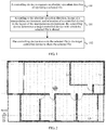
- FIG. 2 is a schematic diagram of a manipulation environment W according to an embodiment of the present invention.
- coordinates may be assigned to W according to actual east, south, west and north.
- a two-dimensional coordinate axis is generated by using a center point of W as an origin and using a recognition precision N as a minimum unit. Therefore, it can be learned that coordinates of La are (3, 4), whose unit is the recognition precision N.
- a controlled device is disposed at the location of La.
- coordinates of other devices such as Lb and Lc are obtained and recorded in the controlling device. It should be noted that a shape of an outer rim of the manipulation environment W is unrestricted.
- an initial location Lo of the mobile phone in layout of a manipulation environment is automatically acquired when the mobile phone is powered on; or a user sets a current location of the mobile phone in the layout of the manipulation environment as the initial location Lo, records coordinates corresponding to Lo, and at the same time enables functions of an acceleration sensor and an electronic compass. Then, the mobile phone acquires a movement direction and a distance of the mobile phone according to the acceleration sensor and the electronic compass at intervals of an update period of time T. According to a comparison with the initial location Lo, a current location Lx of the mobile phone in the layout of the manipulation environment is learnt.
- the mobile phone moves 5N along 30° northeast after the initial location Lo is set. Therefore, according to the Pythagorean theorem, it is deduced that the mobile phone moves 4N east and moves 3N north. If the initial location of Lo is northwest of the origin and the coordinates are (1, -2), Lx is (4, 2) in this case, and so on.
- a calculated current coordinate location of the mobile phone is continuously updated at intervals of the update period of time T.
- the layout of the manipulation environment of the manipulation environment is obtained by recording the movement track of moving in a circle around a rim of the manipulation environment using the manner described in the foregoing embodiment.
- a coordinate location of each controlled device in the manipulation environment may also be identified using the manner described in the foregoing embodiment, and recorded in the mobile phone.
- the step 100 "A controlling device recognizes an absolute operation direction of operating a selected file" may specifically include the following steps, which are described by using an example in which a sensor such as an electronic compass is in standard configuration of a mobile phone:
- the controlling device recognizes the user's operation direction as a specific absolute operation direction.
- step 101 “According to the absolute operation direction and a location of a controlled device in the layout of the manipulation environment, the controlling device determines a target controlled device with which the selected file is shared” may specifically include the following steps:
- FIG. 3 is a status diagram of the manipulation environment W shown in FIG. 2 .
- sensors such as an electronic compass, a gyroscope, and an acceleration sensor are in standard configuration of a mobile phone.
- a controlling device is a mobile phone with a touchscreen.
- the mobile phone recognizes the direction of the user operation relative to a mobile phone screen and the electronic compass recognizes a direction to which the mobile phone is currently facing, and the mobile phone recognizes the user's operation direction as a specific absolute operation direction.
- a reference area of the mobile phone is a cone that uses a current location Lx as a vertex, uses an absolute operation direction P as a vertical line, and uses an identification scope D as a degree of a vertex angle.
- a base side of the reference area of the cone should be the outer rim of the manipulation environment W. Coordinates of locations La, Lb, and Lc...of other devices are compared, and a controlled device within this scope is possible a target controlled device of the user operation.
- the current location Lx of the mobile phone is (4, 2).
- the electronic compass recognizes that the user is dragging a file eastward, the identification scope D is 10°, and a current layout coordinate state is shown in the schematic diagram FIG. 3 .
- a system matching scope is to find a cone whose vertex is Lx (4, 2) and whose vertex angle is 10°.
- a scope of a triangle covered by a cone section is (4, 2) (5, 13) (3, 13). Therefore, according to previous records of device coordinates, Lc (3, 13) falls within this scope, and it may be determined that the user operation is for Lc. That is, it indicates that the selected file in the current mobile phone is shared with the target controlled device at the Lc location.
- the controlling device displays display identifiers of the at least two controlled devices; the controlling device detects information about a selected controlled device; and the controlling device uses the selected controlled device as the target controlled device with which the selected file is shared.
- the information about the selected controlled device is information about the controlled device that is selected by the user.
- the user may select one controlled device by using a touchscreen of the controlling device, and the controlling device detects and determines the information about the controlled device selected by the user, and uses the controlled device as the target controlled device with which the selected file is shared.
- the controlling device may accordingly prompt the user (for example, display related prompt information on the touchscreen), and wait for the user to operate.
- a file transmission method in the foregoing embodiment when a file is transmitted between devices, a user does not need to memorize a model, a name, an icon or a customized identifier of each controlled device, and can transmit a selected file to a controlled device simply by pushing the selected file on the controlling device toward the target controlled device, thereby implementing transmission and sharing of the selected file to the controlled device.
- the technical solution in the embodiment is easy to implement and facilitate an operation, and can effectively improve user experience.
- the program may be stored in a computer readable storage medium.
- the storage medium includes various media capable of storing program codes, such as a ROM, a RAM, a magnetic disk, or an optical disc.
- FIG. 4 is a schematic structural diagram of a controlling device according to an embodiment of the present invention. As shown in FIG. 4 , the controlling device in this embodiment may specifically include an identifying module 10, a determining module 11, and a transmitting module 12.
- the recognizing module 10 is configured to recognize an absolute operation direction of operating a selected file; the determining module 11 is connected to the recognizing module 10, and the determining module 11 is configured to determine, according to the absolute operation direction recognized by the recognizing module 10, layout of a manipulation environment, and a location of a controlled device in the layout of the manipulation environment, a target controlled device with which the selected file is shared, where the layout of the manipulation environment is a structural diagram of a configuration of a manipulation environment in which the controlling device and the controlled device coexist; and the transmitting module 12 is connected to the determining module 11, and the transmitting module 12 is configured to transmit the selected file to the target controlled device determined by the determining module 11, so as to share the selected file.
- the controlling device in this embodiment uses the foregoing modules to implement file transmission, which is based on the same file transmission mechanism as that of the foregoing related method embodiment. For details, reference may be made to the description in the method embodiment, which is not described here repeatedly.
- each layer corresponds to layout of a manipulation environment.
- the recognizing module is further configured to obtain barometric pressure value information and determine the layer at which the controlling device is located, and then switch the current manipulation environment layout to layout of a manipulation environment corresponding to the current layer.
- a controlling device in this embodiment uses the foregoing modules to recognize an absolute operation direction of operating a selected file; determines, according to the absolute operation direction, layout of a manipulation environment, and a location of a controlled device in the layout of the manipulation environment, a target controlled device with which the selected file is shared; and transmits the selected file to the target controlled device to share the selected file.
- a user when a file is transmitted between devices, a user does not need to memorize a model, a name, an icon or a customized identifier of each controlled device, and can transmit a selected file to a controlled device simply by pushing the selected file on the controlling device toward the target controlled device, so that the selected file is transmitted to and shared with the controlled device.
- the technical solution in this embodiment is easy to implement and facilitate an operation, and can effectively improve user experience.
- FIG. 5 is a schematic structural diagram of a controlling device according to another embodiment of the present invention.
- the controlling device in this embodiment may further include the following technical solution:
- the controlling device in this embodiment may further include an acquiring module 13.
- the acquiring module 13 is connected to the determining module 11, and the acquiring module 13 is configured to acquire the layout of the manipulation environment before the determining module 11 determines, according to the absolute operation direction, the layout of the manipulation environment, and the location of the controlled device in the layout of the manipulation environment, the target controlled device with which the selected file is shared.
- the corresponding determining module 11 determines the controlled device with which the selected file is shared.
- the acquiring module 13 is specifically configured to acquire the layout of the manipulation environment from a cloud side or a network side, or is specifically configured to create the layout of the manipulation environment.
- the acquiring module 13 is specifically configured to acquire movement distance information according to an acceleration value acquired by an acceleration sensor.
- sensors such as an electronic compass, a gyroscope, and an acceleration sensor are in standard configuration of a mobile phone.
- the acquiring module 13 is specifically configured to obtain the movement distance information by performing quadratic integral according to the acceleration value acquired by the acceleration sensor; acquire movement direction information of the controlling device according to the electronic compass; acquire a movement track according to the movement distance information and the movement direction information of the controlling device; and obtain the layout of the manipulation environment of a manipulation environment by recording the movement track of moving in a circle around a rim of the manipulation environment.
- the controlling device in this embodiment further includes an identifying module 14.
- the identifying module 14 is separately connected to the acquiring module 13 and the determining module 11, and the identifying module 14 is configured to identify the location of the controlled device in the layout of the manipulation environment after the acquiring module 13 acquires the layout of the manipulation environment and before the determining module 11 determines, according to the absolute operation direction, the layout of the manipulation environment, and the location of the controlled device in the layout of the manipulation environment, the target controlled device with which the selected file is shared, where the layout of the manipulation environment is acquired by the acquiring module 13.
- the corresponding determining module 11 determines the controlled device with which the selected file is shared, where the location is identified by the identifying module 14.
- the recognizing module 10 in the controlling device in this embodiment is specifically configured to recognize an operation direction of operating the selected file on a display screen of the controlling device; determine a current geographic direction according to the electronic compass; and, determine, according to the operation direction in which a user performs an operation on the selected file on the display screen of the controlling device and the current geographic direction, the absolute operation direction of operating the selected file.
- the determining module 11 in the controlling device in this embodiment is specifically configured to: acquire a reference area of the location of the controlled device, where the reference area is an area determined by using an operation start point of the selected file on the display screen of the controlling device as a vertex, by using the absolute operation direction as an angle bisector or a side of an angle, and by using an identification scope of a vertex angle as an angle; acquire a controlled device in the reference area according to the location of the controlled device in the layout of the manipulation environment, where the location is identified by the identifying module 14; and use the controlled device in the reference area as the target controlled device with which the selected file is shared.
- the determining module 11 in the controlling device in this embodiment is further configured to: when the reference area includes at least two controlled devices, display display identifiers of the at least two controlled devices; detect information about a selected controlled device; and use the selected controlled device as the target controlled device with which the selected file is shared.
- FIG. 5 describes the technical solution of the present invention by using an example in which various aforementioned solutions are included.
- the various aforementioned technical solutions may be combined in any manner to form an optional technical solution of the embodiment of the present invention, which is not described here repeatedly.
- the controlling device in this embodiment uses the foregoing modules to implement file transmission, which is based on the same file transmission mechanism as that of the foregoing related method embodiment. For details, reference may be made to the description in the method embodiment, which is not described here repeatedly.
- a controlling device in this embodiment, which uses the foregoing modules, when a file is transmitted between devices, a user does not need to memorize a model, a name, an icon or a customized identifier of each controlled device, and can transmit a selected file to a controlled device simply by pushing the selected file on the controlling device toward the target controlled device, so that the selected file is transmitted to and shared with the controlled device.
- the technical solution in this embodiment is easy to implement and facilitate an operation, and can effectively improve user experience.
- FIG. 6 is a schematic structural diagram of a mobile terminal used as a controlling device according to an embodiment of the present invention.
- the mobile terminal in this embodiment may include a mobile phone, a tablet computer, a PDA (Personal Digital Assistant, personal digital assistant), a POS (Point of Sales, point of sales), or a vehicle-mounted computer, or the like.
- PDA Personal Digital Assistant
- POS Point of Sales, point of sales
- vehicle-mounted computer or the like.
- FIG. 6 is a block diagram of a partial structure of a mobile phone 600 related to this embodiment of the present invention.
- the mobile phone 600 includes components such as an RF (Radio Frequency, radio frequency) circuit 610, a memory 620, an input unit 630, a display 640, a sensor 650, an audio circuit 660, a WiFi (wireless fidelity, wireless fidelity) module 670, a processor 680, and a power supply 690.
- RF Radio Frequency, radio frequency
- the mobile phone structure shown in FIG. 6 constitutes no limitation on the mobile phone, and the mobile phone may include more or fewer components than the shown components, some components may be combined, or the components may be disposed differently.
- the RF circuit 610 may be configured to receive and send a signal in an information sending or receiving process or a call process, and in particular, after receiving downlink information of a base station, send the downlink information to the processor 680 for processing; and in addition, send designed uplink data to the base station.
- the RF circuit includes but is not limited to an antenna, at least one amplifier, a transceiver, a coupler, an LNA (Low Noise Amplifier, low noise amplifier), a duplexer, and the like.
- the RF circuit 610 may also communicate with a network and other devices by means of radio communication.
- the radio communication may use any communication standard or protocol, including but not limited to GSM (Global System of Mobile communication, Global System of Mobile Communications), GPRS (General Packet Radio Service, General Packet Radio Service), CDMA (Code Division Multiple Access, Code Division Multiple Access), WCDMA (Wideband Code Division Multiple Access, Wideband Code Division Multiple Access), LTE (Long Term Evolution, Long Term Evolution), email, SMS (Short Messaging Service, short messaging service), and the like.
- GSM Global System of Mobile communication, Global System of Mobile Communications
- GPRS General Packet Radio Service, General Packet Radio Service
- CDMA Code Division Multiple Access, Code Division Multiple Access
- WCDMA Wideband Code Division Multiple Access
- LTE Long Term Evolution, Long Term Evolution
- SMS Short Messaging Service, short messaging service
- the memory 620 may be configured to store a software program and a module, and the processor 680 executes various function applications of the mobile phone 600 and performs data processing by running the software program and the module that are stored in the memory 620.
- the memory 620 may primarily include a program storage area and a data storage area, where the program storage area may store an operating system, and an application required by at least one function (such as an audio playback function or a video playback function), and the like; and the data storage area may store data (such as audio data or a phone book) created according to use of the mobile phone 600, and the like.
- the memory 620 may include a high-speed random access memory, and may further include a non-volatile memory, for example, at least one disk memory component, one flash memory component, or another volatile solid-state memory component.
- the input unit 630 may be configured to receive an entered numeral or character information, and generate a key signal input related to a user setting and function control of the mobile phone 600.
- the input unit 630 may include a touch panel 631 and other input devices 632.
- the touch panel 631 is also referred to as a touchscreen and can collect a touch operation (such as an operation performed by a user on the touch panel 631 or near the touch panel 631 by using a finger or any proper object or accessory such as a stylus) on or near the touch panel, and drive a corresponding connection apparatus according to a preset program.
- the touch panel 631 may include two parts: a touch detection apparatus and a touch controller.
- the touch detection apparatus detects a touch position of the user, detects a signal brought by the touch operation, and sends the signal to the touch controller.
- the touch controller receives touch information from the touch detection apparatus, converts the touch information into touch coordinates, and sends the touch coordinates to the processor 680, and can receive a command sent by the processor 680 and execute the command.
- the touch panel 631 may be implemented in multiple types, such as resistive, capacitive, infrared, and surface acoustic wave.
- the input unit 630 may include other input devices 632 in addition to the touch panel 631. Specifically, other input devices 632 may include but are not limited to one or more among a physical keyboard, a function key (such as a volume control key or a switch key), a trackball, a mouse, a joystick, or the like.
- the display 640 may be configured to display information entered by the user or information provided for the user, and various menus of the mobile phone 600.
- the display 640 may include a display panel 641.
- the display panel 641 may be configured in a form such as an LCD (Liquid Crystal Display, liquid crystal display) or an OLED (Organic Light-Emitting Diode, organic light-emitting diode).
- the touch panel 631 may cover the display panel 641. When detecting a touch operation on or near the touch panel, the touch panel 631 transmits the touch operation to the processor 680 to determine a type of a touch event, and then the processor 680 provides a corresponding visual output on the display panel 641 according to the type of the touch event.
- touch panel 631 and the display panel 641 in FIG. 6 are used as two independent parts to implement input and output functions of the mobile phone 600, in some embodiments, the touch panel 631 and the display panel 641 may be integrated to implement the input and output functions of the mobile phone 600.
- the mobile phone 600 may further include at least one sensor 650, such as an electronic compass, a gyroscope, or an acceleration sensor, and the sensor may be an integrated sensor that integrates the electronic compass, the gyroscope, the acceleration sensor, and the like to function as a component, such as a 10-axis sensor.
- an optical sensor may include an environment optical sensor and an proximity sensor. The environment optical sensor may adjust luminance of the display panel 641 according to brightness or dimness of environment light, and the approach sensor may close the display panel 641 or backlight or both when the mobile phone 600 approaches an ear.
- the acceleration sensor can detect an acceleration value in each direction (generally three axes), and detect a value and a direction of gravity when the acceleration sensor is static, and is applicable to an application for recognizing a mobile phone posture (for example, a switch between landscape and portrait screens, related games, and magnetometer posture calibration), a function related to vibration recognition (such as a pedometer or a knock), and the like.
- Other sensors such as a gyroscope, a barometer, a hygrometer, a thermometer, and an infrared sensor may also be disposed on the mobile phone 600, which is not described here repeatedly.
- An audio circuit 660, a speaker 661, and a microphone 662 may provide audio interfaces between the user and the mobile phone 600.
- the audio circuit 660 may transmit an electric signal to the speaker 661, where the electric signal is a result of converting received audio data, and the speaker 661 converts the electric signal into a sound signal for outputting.
- the microphone 662 converts a collected sound signal into an electric signal, and the audio circuit 660 receives the electric signal and converts it into audio data, and then outputs the audio data to an RF circuit 608 so that the audio data is sent to, for example, another mobile phone, or the audio data is output to a memory 620 for further processing.
- WiFi is a short-distance radio transmission technology.
- the mobile phone 600 uses a WiFi module 670 to help the user send and receive an email, browse a web page, gain access to streaming media, and the like.
- the WiFi module provides the user with wireless broadband Internet access.
- FIG. 6 shows the WiFi module 670, understandably the WiFi module is not a mandatory part of the mobile phone 600, and may completely be omitted according to a requirement without changing the essence of the present invention.
- the processor 680 is a control center of the mobile phone 600, and uses various interfaces and lines to connect all parts of the entire mobile phone. By running or executing a software program or a module or both that are stored in the memory 620 and invoking data stored in the memory 620, the processor executes various functions of the mobile phone 600 and processes data so as to perform overall monitoring on the mobile phone.
- the processor 680 may include one or more processing units.
- an application processor and a modem processor may be integrated into the processor 680, where the application processor primarily processes an operating system, a user interface, an application, and the like; and the modem processor primarily handles radio communication. Understandably, the modem processor is not necessarily integrated into the processor 180.
- the mobile phone 600 further includes a power supply 690 (such as a battery) that supplies power to each component.
- a power supply 690 such as a battery
- the power supply may be logically connected to the processor 680 by using a power supply management system. In this way, functions such as management of charging, discharging, and power consumption are implemented by using the power supply management system.
- the mobile phone 600 may further include a camera, a Bluetooth module, and the like, which are not shown in the diagram though and are not described here repeatedly.
- the processor 680 recognizes an absolute operation direction of operating a selected file; and determines, according to the recognized absolute operation direction, layout of a manipulation environment, and a location of a controlled device in the layout of the manipulation environment, a target controlled device with which the selected file is shared; and transmits the selected file to the determined target controlled device to share the selected file.
- the layout of the manipulation environment is a structural diagram of a configuration of a manipulation environment in which the controlling device and the controlled device coexist.
- the processor 680 may further acquire the layout of the manipulation environment before determining, according to the absolute operation direction, the layout of the manipulation environment, and the location of the target controlled device in the layout of the manipulation environment, the controlled device with which the selected file is shared.
- the processor 680 may acquire the layout of the manipulation environment from a cloud side or a network side, or the processor 680 may specifically create the layout of the manipulation environment.
- the processor 680 may specifically acquire movement distance information according to the acceleration value acquired by the acceleration sensor (for example, specifically, obtain the movement distance information by performing quadratic integral according to the acceleration value acquired by the acceleration sensor); acquire movement direction information of the controlling device according to the electronic compass; acquire a movement track according to the movement distance information and the movement direction information of the controlling device; and obtain the layout of the manipulation environment of a manipulation environment by recording the movement track of moving in a circle around a rim of the manipulation environment.
- the acceleration sensor for example, specifically, obtain the movement distance information by performing quadratic integral according to the acceleration value acquired by the acceleration sensor
- acquire movement direction information of the controlling device according to the electronic compass acquire a movement track according to the movement distance information and the movement direction information of the controlling device
- obtain the layout of the manipulation environment of a manipulation environment by recording the movement track of moving in a circle around a rim of the manipulation environment.
- the processor 680 may identify the location of the controlled device in the acquired manipulation environment layout after acquiring the layout of the manipulation environment and before determining, according to the absolute operation direction, the layout of the manipulation environment, and the location of the controlled device in the layout of the manipulation environment, the target controlled device with which the selected file is shared.
- the processor 680 may further recognize an operation direction of operating the selected file on a display screen of the controlling device; determine a current geographic direction according to the electronic compass; and determine, according to the operation direction in which a user performs an operation on the selected file on the display screen of the controlling device and the current geographic direction, the absolute operation direction of operating the selected file.
- the processor 680 may further acquire a reference area of the location of the controlled device, where the reference area is an area determined by using an operation start point of the selected file on the display screen of the controlling device as a vertex, by using the absolute operation direction as an angle bisector or a side of an angle, and by using an identification scope of a vertex angle as an angle; acquire a controlled device in the reference area according to the identified location of the controlled device in the layout of the manipulation environment; and use the controlled device in the reference area as the target controlled device with which the selected file is shared.
- the reference area is an area determined by using an operation start point of the selected file on the display screen of the controlling device as a vertex, by using the absolute operation direction as an angle bisector or a side of an angle, and by using an identification scope of a vertex angle as an angle
- the display 640 may display display identifiers of the at least two controlled devices; and the processor 680 detects information about a selected controlled device and uses the selected controlled device as the target controlled device with which the selected file is shared.
- each layer corresponds to layout of a manipulation environment.
- the processor 680 is further configured to receive barometric pressure value information sent by the sensor and determine the layer at which the controlling device is located, and then switch the current manipulation environment layout to layout of a manipulation environment corresponding to the current layer.
- a processor recognizes an absolute operation direction of operating a selected file; and determines, according to the absolute operation direction, layout of a manipulation environment, and a location of a controlled device in the layout of the manipulation environment, a target controlled device with which the selected file is shared, where the layout of the manipulation environment is a structural diagram of a configuration of a manipulation environment in which the controlling device and the controlled device coexist; and transmits the selected file to the target controlled device to share the selected file.
- a user when a file is transmitted between devices, a user does not need to memorize a model, a name, an icon or a customized identifier of each controlled device, and can transmit a selected file to a controlled device simply by pushing the selected file on the controlling device toward the target controlled device, so that the selected file is transmitted to and shared with the controlled device.
- the technical solution in this embodiment is easy to implement and facilitate an operation, and can effectively improve user experience.
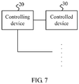
- FIG. 7 is a structural diagram of a file transmission system according to an embodiment of the present invention.
- the file transmission system in this embodiment includes a controlling device 20 and at least one controlled device 30, where the controlling device 20 and the at least one controlled device 30 are in a same manipulation environment.
- the controlling device 20 may have a communication connection with the at least one controlled device 30, and send the selected file to the controlled device 30 to share the selected file.
- the controlling device 20 is configured to: recognize an absolute operation direction of operating a selected file; determine, according to the recognized absolute operation direction, layout of a manipulation environment, and a location of at least one controlled device in the layout of the manipulation environment, a target controlled device with which the selected file is shared; and transmit the selected file to the determined target controlled device to share the selected file.
- controlling device 20 is the controlling device shown in FIG. 4 , FIG. 5, or FIG. 6 .
- the controlling device may be a controlling device described in the embodiment shown in FIG. 1 and subsequent optional embodiments.
- the file transmission system in this embodiment uses the controlling device to implement file transmission, which is based on the same file transmission mechanism as that of the foregoing related method embodiment. For details, reference may be made to the description in the method embodiment, which is not described here repeatedly.
- a file transmission system in this embodiment uses the foregoing controlling device to recognize an absolute operation direction of operating a selected file; determines, according to the absolute operation direction, layout of a manipulation environment, and a location of at least one controlled device in the layout of the manipulation environment, a target controlled device with which the selected file is shared; and transmits the selected file to the target controlled device to share the selected file.
- a user when a file is transmitted between devices, a user does not need to memorize a model, a name, an icon or a customized identifier of each controlled device, and can transmit a selected file to a controlled device simply by pushing the selected file on the controlling device toward the target controlled device, so that the selected file is transmitted to and shared with the controlled device.
- the technical solution in this embodiment is easy to implement and facilitate an operation, and can effectively improve user experience.
- the controlling device in this embodiment of the present invention may be a tablet computer, a mobile phone with a touchscreen, or the like; and the controlled device may be an acoustic system, a television set, or a desktop computer or the like, or may be a mobile phone with a touchscreen, a mobile phone with an ordinary screen (that is, a mobile phone with a non-touchscreen), or a tablet computer, or the like.
- the apparatus embodiment described above is merely illustrative; the units described as separate parts may or may not be physically separate, and the parts displayed as units may or may not be physical units, may be located in one location, or may be distributed on at least two network units; and a part or all of the modules may be selected according to actual needs to achieve the objectives of the solutions of the embodiments, which may be understood and implemented by a person of ordinary skill in the art without making creative efforts.
Landscapes
- Engineering & Computer Science (AREA)
- Computer Networks & Wireless Communication (AREA)
- Signal Processing (AREA)
- Theoretical Computer Science (AREA)
- General Engineering & Computer Science (AREA)
- Physics & Mathematics (AREA)
- Human Computer Interaction (AREA)
- General Physics & Mathematics (AREA)
- Multimedia (AREA)
- User Interface Of Digital Computer (AREA)
- Telephone Function (AREA)
- Selective Calling Equipment (AREA)
- Telephonic Communication Services (AREA)
Applications Claiming Priority (2)
| Application Number | Priority Date | Filing Date | Title |
|---|---|---|---|
| CN201210363524.8A CN102932412B (zh) | 2012-09-26 | 2012-09-26 | 文件传输方法及系统、主控设备 |
| PCT/CN2013/072980 WO2014048093A1 (zh) | 2012-09-26 | 2013-03-21 | 文件传输方法及系统、主控设备 |
Publications (3)
| Publication Number | Publication Date |
|---|---|
| EP2802124A1 EP2802124A1 (en) | 2014-11-12 |
| EP2802124A4 EP2802124A4 (en) | 2015-02-18 |
| EP2802124B1 true EP2802124B1 (en) | 2019-09-25 |
Family
ID=47647109
Family Applications (1)
| Application Number | Title | Priority Date | Filing Date |
|---|---|---|---|
| EP13840359.7A Active EP2802124B1 (en) | 2012-09-26 | 2013-03-21 | Method and system for file transfer, and main control device |
Country Status (6)
Families Citing this family (17)
| Publication number | Priority date | Publication date | Assignee | Title |
|---|---|---|---|---|
| CN102932412B (zh) * | 2012-09-26 | 2016-02-03 | 华为终端有限公司 | 文件传输方法及系统、主控设备 |
| CN104010204B (zh) * | 2013-02-27 | 2018-05-08 | 中国移动通信集团公司 | 图像信息处理方法及装置 |
| CN103198822B (zh) * | 2013-04-19 | 2015-12-09 | 广州市天汇计算机科技有限公司 | 一种具有无线推送功能的卡拉ok播控设备 |
| CN103338221B (zh) * | 2013-05-20 | 2017-10-24 | 魅族科技(中国)有限公司 | 数据传递、数据接收的方法和终端 |
| US9749395B2 (en) | 2013-05-31 | 2017-08-29 | International Business Machines Corporation | Work environment for information sharing and collaboration |
| US9537908B2 (en) * | 2013-06-11 | 2017-01-03 | Microsoft Technology Licensing, Llc | Collaborative mobile interaction |
| CN103595775B (zh) * | 2013-11-04 | 2018-01-19 | 惠州Tcl移动通信有限公司 | 媒体文件的共享方法及系统 |
| CN104506907B (zh) * | 2014-11-25 | 2018-03-13 | 上海众应信息科技有限公司 | 控制端与多个远程被控终端之间的交互操作方法及系统 |
| CN105809917A (zh) * | 2014-12-29 | 2016-07-27 | 中国移动通信集团公司 | 一种物联网消息传输的方法及设备 |
| CN104580511B (zh) * | 2015-01-27 | 2016-03-23 | 深圳市中兴移动通信有限公司 | 终端间文件传输方法和系统 |
| CN105992152A (zh) * | 2015-03-06 | 2016-10-05 | 中国移动通信集团辽宁有限公司 | 一种信息处理方法和终端 |
| CN106470478B (zh) * | 2015-08-20 | 2020-03-24 | 西安云景智维科技有限公司 | 一种定位数据处理方法、装置和系统 |
| CN106291646A (zh) * | 2016-08-15 | 2017-01-04 | 武汉中元通信股份有限公司 | 手持式s频段卫星/4g手机通信与北斗/gps定位装置 |
| WO2018173121A1 (ja) * | 2017-03-21 | 2018-09-27 | 株式会社Preferred Networks | サーバ装置、学習済モデル提供プログラム、学習済モデル提供方法及び学習済モデル提供システム |
| CN107241395A (zh) * | 2017-05-24 | 2017-10-10 | 努比亚技术有限公司 | 一种共享文件的传输方法、设备及计算机可读存储介质 |
| CN113810542B (zh) * | 2020-05-27 | 2022-10-28 | 华为技术有限公司 | 一种应用于电子设备的控制方法、电子设备及计算机存储介质 |
| CN115943621A (zh) * | 2020-05-27 | 2023-04-07 | 华为技术有限公司 | 一种应用于电子设备的控制方法及电子设备 |
Family Cites Families (22)
| Publication number | Priority date | Publication date | Assignee | Title |
|---|---|---|---|---|
| JP2002286492A (ja) * | 2001-03-26 | 2002-10-03 | Denso Corp | 携帯型ナビゲーション装置 |
| JP2002290606A (ja) * | 2001-03-27 | 2002-10-04 | Tdk Corp | 無線通信端末及び無線ネットワークシステムにおける接続機器の選択方法 |
| US7716585B2 (en) * | 2003-08-28 | 2010-05-11 | Microsoft Corporation | Multi-dimensional graphical display of discovered wireless devices |
| JP3841220B2 (ja) * | 2004-01-30 | 2006-11-01 | 船井電機株式会社 | 自律走行ロボットクリーナー |
| JP2007333998A (ja) * | 2006-06-15 | 2007-12-27 | Hitachi Ltd | 地図の自動生成装置 |
| JP2008299619A (ja) * | 2007-05-31 | 2008-12-11 | Toshiba Corp | モバイル機器、データ転送方法、およびデータ転送システム |
| US20090017799A1 (en) * | 2007-07-13 | 2009-01-15 | Sony Ericsson Mobile Communications Ab | System, device and method for transmitting a file by use of a throwing gesture to a mobile terminal |
| US20090195445A1 (en) * | 2008-01-31 | 2009-08-06 | Dehaas Ronald J | System and method for selecting parameters based on physical location of a computer device |
| US20100274852A1 (en) * | 2009-04-28 | 2010-10-28 | Nokia Corporation | Method and Apparatus for Sharing Context to One or More Users |
| US9571625B2 (en) * | 2009-08-11 | 2017-02-14 | Lg Electronics Inc. | Electronic device and control method thereof |
| US8457651B2 (en) * | 2009-10-02 | 2013-06-04 | Qualcomm Incorporated | Device movement user interface gestures for file sharing functionality |
| TW201115451A (en) * | 2009-10-20 | 2011-05-01 | Ind Tech Res Inst | A vectoring data transfer system and method based on sensor assisted positioning method |
| US20110162048A1 (en) * | 2009-12-31 | 2011-06-30 | Apple Inc. | Local device awareness |
| JP5488011B2 (ja) * | 2010-02-04 | 2014-05-14 | ソニー株式会社 | 通信制御装置、通信制御方法及びプログラム |
| GB201017711D0 (en) * | 2010-10-20 | 2010-12-01 | Sonitor Technologies As | Position determination system |
| US20120173204A1 (en) * | 2010-12-30 | 2012-07-05 | Honeywell International Inc. | Building map generation using location and tracking data |
| US9055162B2 (en) * | 2011-02-15 | 2015-06-09 | Lg Electronics Inc. | Method of transmitting and receiving data, display device and mobile terminal using the same |
| CN102843280B (zh) * | 2011-06-24 | 2015-03-25 | 联想(北京)有限公司 | 通信设备的通信方法、系统及通信设备 |
| CN102447969A (zh) * | 2011-08-25 | 2012-05-09 | 深圳市同洲电子股份有限公司 | 移动终端与数字电视接收终端进行数据交互的方法及系统 |
| CN102377823B (zh) * | 2011-10-18 | 2013-12-25 | 北京优朋普乐科技有限公司 | 一种通过滑屏实现多屏多用户之间互动分享的方法及系统 |
| US20140022183A1 (en) * | 2012-07-19 | 2014-01-23 | General Instrument Corporation | Sending and receiving information |
| CN102932412B (zh) * | 2012-09-26 | 2016-02-03 | 华为终端有限公司 | 文件传输方法及系统、主控设备 |
-
2012
- 2012-09-26 CN CN201210363524.8A patent/CN102932412B/zh active Active
-
2013
- 2013-03-21 KR KR1020147023599A patent/KR101602309B1/ko active Active
- 2013-03-21 WO PCT/CN2013/072980 patent/WO2014048093A1/zh active Application Filing
- 2013-03-21 JP JP2014559079A patent/JP5916261B2/ja active Active
- 2013-03-21 EP EP13840359.7A patent/EP2802124B1/en active Active
-
2014
- 2014-12-12 US US14/568,413 patent/US20150100900A1/en not_active Abandoned
Non-Patent Citations (1)
| Title |
|---|
| None * |
Also Published As
| Publication number | Publication date |
|---|---|
| EP2802124A1 (en) | 2014-11-12 |
| KR101602309B1 (ko) | 2016-03-21 |
| WO2014048093A1 (zh) | 2014-04-03 |
| EP2802124A4 (en) | 2015-02-18 |
| US20150100900A1 (en) | 2015-04-09 |
| CN102932412B (zh) | 2016-02-03 |
| CN102932412A (zh) | 2013-02-13 |
| JP2015513389A (ja) | 2015-05-11 |
| KR20140115370A (ko) | 2014-09-30 |
| JP5916261B2 (ja) | 2016-05-11 |
Similar Documents
| Publication | Publication Date | Title |
|---|---|---|
| EP2802124B1 (en) | Method and system for file transfer, and main control device | |
| AU2021269359B2 (en) | Display method and apparatus | |
| US10798544B2 (en) | Method for exchanging data with in-vehicle infotainment, server, mobile terminal, and apparatus | |
| CN107943489B (zh) | 数据分享方法及移动终端 | |
| CN105100390A (zh) | 移动终端和用于控制该移动终端的方法 | |
| CN106225792A (zh) | 通信终端及群组化领航、导航方法和装置 | |
| CN109932686A (zh) | 一种定位方法、移动终端及室内定位系统 | |
| CN104360307B (zh) | 一种定位方法和装置 | |
| KR101680667B1 (ko) | 이동 단말기 및 이동 단말기의 제어방법 | |
| EP3429176B1 (en) | Scenario-based sound effect control method and electronic device | |
| CN110427165B (zh) | 一种图标显示方法及移动终端 | |
| JP2017509051A (ja) | ストリーミングメディアデータに関する統計を収集するための方法およびシステム、ならびに関連する装置 | |
| CN108917766B (zh) | 一种导航方法和移动终端 | |
| CN110708673A (zh) | 一种位置确定方法和便捷式多功能设备 | |
| EP3105912B1 (en) | Application-based service providing method and system | |
| CN108632470B (zh) | 一种无线网络信号的显示方法及移动终端 | |
| CN108988413B (zh) | 一种移动终端充电的方法和移动终端 | |
| WO2014201839A1 (en) | Method and device for searching for parent virus | |
| EP3244598A1 (en) | User terminal dialing method and user terminal | |
| EP3402162B1 (en) | Terminal device and control method therefor | |
| CN108595081A (zh) | 一种转动控制的方法及终端 | |
| WO2019042479A1 (zh) | 基于陀螺仪的指纹操控方法、移动终端及存储介质 | |
| HK1204398A1 (en) | Method, terminal and system for geographical location sharing | |
| HK1204398B (en) | Method, terminal and system for geographical location sharing |
Legal Events
| Date | Code | Title | Description |
|---|---|---|---|
| PUAI | Public reference made under article 153(3) epc to a published international application that has entered the european phase |
Free format text: ORIGINAL CODE: 0009012 |
|
| 17P | Request for examination filed |
Effective date: 20140804 |
|
| AK | Designated contracting states |
Kind code of ref document: A1 Designated state(s): AL AT BE BG CH CY CZ DE DK EE ES FI FR GB GR HR HU IE IS IT LI LT LU LV MC MK MT NL NO PL PT RO RS SE SI SK SM TR |
|
| A4 | Supplementary search report drawn up and despatched |
Effective date: 20150116 |
|
| RIC1 | Information provided on ipc code assigned before grant |
Ipc: H04L 29/08 20060101AFI20150112BHEP |
|
| DAX | Request for extension of the european patent (deleted) | ||
| RAP1 | Party data changed (applicant data changed or rights of an application transferred) |
Owner name: HUAWEI DEVICE (DONGGUAN) CO., LTD. |
|
| STAA | Information on the status of an ep patent application or granted ep patent |
Free format text: STATUS: EXAMINATION IS IN PROGRESS |
|
| 17Q | First examination report despatched |
Effective date: 20181029 |
|
| GRAP | Despatch of communication of intention to grant a patent |
Free format text: ORIGINAL CODE: EPIDOSNIGR1 |
|
| STAA | Information on the status of an ep patent application or granted ep patent |
Free format text: STATUS: GRANT OF PATENT IS INTENDED |
|
| RAP1 | Party data changed (applicant data changed or rights of an application transferred) |
Owner name: HUAWEI DEVICE CO., LTD. |
|
| INTG | Intention to grant announced |
Effective date: 20190425 |
|
| GRAS | Grant fee paid |
Free format text: ORIGINAL CODE: EPIDOSNIGR3 |
|
| GRAA | (expected) grant |
Free format text: ORIGINAL CODE: 0009210 |
|
| STAA | Information on the status of an ep patent application or granted ep patent |
Free format text: STATUS: THE PATENT HAS BEEN GRANTED |
|
| AK | Designated contracting states |
Kind code of ref document: B1 Designated state(s): AL AT BE BG CH CY CZ DE DK EE ES FI FR GB GR HR HU IE IS IT LI LT LU LV MC MK MT NL NO PL PT RO RS SE SI SK SM TR |
|
| REG | Reference to a national code |
Ref country code: GB Ref legal event code: FG4D |
|
| REG | Reference to a national code |
Ref country code: CH Ref legal event code: EP |
|
| REG | Reference to a national code |
Ref country code: AT Ref legal event code: REF Ref document number: 1184943 Country of ref document: AT Kind code of ref document: T Effective date: 20191015 |
|
| REG | Reference to a national code |
Ref country code: IE Ref legal event code: FG4D |
|
| REG | Reference to a national code |
Ref country code: DE Ref legal event code: R096 Ref document number: 602013061058 Country of ref document: DE |
|
| REG | Reference to a national code |
Ref country code: NL Ref legal event code: MP Effective date: 20190925 |
|
| PG25 | Lapsed in a contracting state [announced via postgrant information from national office to epo] |
Ref country code: HR Free format text: LAPSE BECAUSE OF FAILURE TO SUBMIT A TRANSLATION OF THE DESCRIPTION OR TO PAY THE FEE WITHIN THE PRESCRIBED TIME-LIMIT Effective date: 20190925 Ref country code: LT Free format text: LAPSE BECAUSE OF FAILURE TO SUBMIT A TRANSLATION OF THE DESCRIPTION OR TO PAY THE FEE WITHIN THE PRESCRIBED TIME-LIMIT Effective date: 20190925 Ref country code: BG Free format text: LAPSE BECAUSE OF FAILURE TO SUBMIT A TRANSLATION OF THE DESCRIPTION OR TO PAY THE FEE WITHIN THE PRESCRIBED TIME-LIMIT Effective date: 20191225 Ref country code: SE Free format text: LAPSE BECAUSE OF FAILURE TO SUBMIT A TRANSLATION OF THE DESCRIPTION OR TO PAY THE FEE WITHIN THE PRESCRIBED TIME-LIMIT Effective date: 20190925 Ref country code: FI Free format text: LAPSE BECAUSE OF FAILURE TO SUBMIT A TRANSLATION OF THE DESCRIPTION OR TO PAY THE FEE WITHIN THE PRESCRIBED TIME-LIMIT Effective date: 20190925 Ref country code: NO Free format text: LAPSE BECAUSE OF FAILURE TO SUBMIT A TRANSLATION OF THE DESCRIPTION OR TO PAY THE FEE WITHIN THE PRESCRIBED TIME-LIMIT Effective date: 20191225 |
|
| REG | Reference to a national code |
Ref country code: LT Ref legal event code: MG4D |
|
| PG25 | Lapsed in a contracting state [announced via postgrant information from national office to epo] |
Ref country code: LV Free format text: LAPSE BECAUSE OF FAILURE TO SUBMIT A TRANSLATION OF THE DESCRIPTION OR TO PAY THE FEE WITHIN THE PRESCRIBED TIME-LIMIT Effective date: 20190925 Ref country code: RS Free format text: LAPSE BECAUSE OF FAILURE TO SUBMIT A TRANSLATION OF THE DESCRIPTION OR TO PAY THE FEE WITHIN THE PRESCRIBED TIME-LIMIT Effective date: 20190925 Ref country code: GR Free format text: LAPSE BECAUSE OF FAILURE TO SUBMIT A TRANSLATION OF THE DESCRIPTION OR TO PAY THE FEE WITHIN THE PRESCRIBED TIME-LIMIT Effective date: 20191226 |
|
| REG | Reference to a national code |
Ref country code: AT Ref legal event code: MK05 Ref document number: 1184943 Country of ref document: AT Kind code of ref document: T Effective date: 20190925 |
|
| PG25 | Lapsed in a contracting state [announced via postgrant information from national office to epo] |
Ref country code: ES Free format text: LAPSE BECAUSE OF FAILURE TO SUBMIT A TRANSLATION OF THE DESCRIPTION OR TO PAY THE FEE WITHIN THE PRESCRIBED TIME-LIMIT Effective date: 20190925 Ref country code: PT Free format text: LAPSE BECAUSE OF FAILURE TO SUBMIT A TRANSLATION OF THE DESCRIPTION OR TO PAY THE FEE WITHIN THE PRESCRIBED TIME-LIMIT Effective date: 20200127 Ref country code: PL Free format text: LAPSE BECAUSE OF FAILURE TO SUBMIT A TRANSLATION OF THE DESCRIPTION OR TO PAY THE FEE WITHIN THE PRESCRIBED TIME-LIMIT Effective date: 20190925 Ref country code: AL Free format text: LAPSE BECAUSE OF FAILURE TO SUBMIT A TRANSLATION OF THE DESCRIPTION OR TO PAY THE FEE WITHIN THE PRESCRIBED TIME-LIMIT Effective date: 20190925 Ref country code: RO Free format text: LAPSE BECAUSE OF FAILURE TO SUBMIT A TRANSLATION OF THE DESCRIPTION OR TO PAY THE FEE WITHIN THE PRESCRIBED TIME-LIMIT Effective date: 20190925 Ref country code: IT Free format text: LAPSE BECAUSE OF FAILURE TO SUBMIT A TRANSLATION OF THE DESCRIPTION OR TO PAY THE FEE WITHIN THE PRESCRIBED TIME-LIMIT Effective date: 20190925 Ref country code: EE Free format text: LAPSE BECAUSE OF FAILURE TO SUBMIT A TRANSLATION OF THE DESCRIPTION OR TO PAY THE FEE WITHIN THE PRESCRIBED TIME-LIMIT Effective date: 20190925 Ref country code: NL Free format text: LAPSE BECAUSE OF FAILURE TO SUBMIT A TRANSLATION OF THE DESCRIPTION OR TO PAY THE FEE WITHIN THE PRESCRIBED TIME-LIMIT Effective date: 20190925 Ref country code: AT Free format text: LAPSE BECAUSE OF FAILURE TO SUBMIT A TRANSLATION OF THE DESCRIPTION OR TO PAY THE FEE WITHIN THE PRESCRIBED TIME-LIMIT Effective date: 20190925 |
|
| PG25 | Lapsed in a contracting state [announced via postgrant information from national office to epo] |
Ref country code: SM Free format text: LAPSE BECAUSE OF FAILURE TO SUBMIT A TRANSLATION OF THE DESCRIPTION OR TO PAY THE FEE WITHIN THE PRESCRIBED TIME-LIMIT Effective date: 20190925 Ref country code: CZ Free format text: LAPSE BECAUSE OF FAILURE TO SUBMIT A TRANSLATION OF THE DESCRIPTION OR TO PAY THE FEE WITHIN THE PRESCRIBED TIME-LIMIT Effective date: 20190925 Ref country code: IS Free format text: LAPSE BECAUSE OF FAILURE TO SUBMIT A TRANSLATION OF THE DESCRIPTION OR TO PAY THE FEE WITHIN THE PRESCRIBED TIME-LIMIT Effective date: 20200224 Ref country code: SK Free format text: LAPSE BECAUSE OF FAILURE TO SUBMIT A TRANSLATION OF THE DESCRIPTION OR TO PAY THE FEE WITHIN THE PRESCRIBED TIME-LIMIT Effective date: 20190925 |
|
| REG | Reference to a national code |
Ref country code: DE Ref legal event code: R097 Ref document number: 602013061058 Country of ref document: DE |
|
| PG2D | Information on lapse in contracting state deleted |
Ref country code: IS |
|
| PG25 | Lapsed in a contracting state [announced via postgrant information from national office to epo] |
Ref country code: DK Free format text: LAPSE BECAUSE OF FAILURE TO SUBMIT A TRANSLATION OF THE DESCRIPTION OR TO PAY THE FEE WITHIN THE PRESCRIBED TIME-LIMIT Effective date: 20190925 Ref country code: IS Free format text: LAPSE BECAUSE OF FAILURE TO SUBMIT A TRANSLATION OF THE DESCRIPTION OR TO PAY THE FEE WITHIN THE PRESCRIBED TIME-LIMIT Effective date: 20200126 |
|
| PLBE | No opposition filed within time limit |
Free format text: ORIGINAL CODE: 0009261 |
|
| STAA | Information on the status of an ep patent application or granted ep patent |
Free format text: STATUS: NO OPPOSITION FILED WITHIN TIME LIMIT |
|
| 26N | No opposition filed |
Effective date: 20200626 |
|
| PG25 | Lapsed in a contracting state [announced via postgrant information from national office to epo] |
Ref country code: MC Free format text: LAPSE BECAUSE OF FAILURE TO SUBMIT A TRANSLATION OF THE DESCRIPTION OR TO PAY THE FEE WITHIN THE PRESCRIBED TIME-LIMIT Effective date: 20190925 |
|
| REG | Reference to a national code |
Ref country code: CH Ref legal event code: PL |
|
| PG25 | Lapsed in a contracting state [announced via postgrant information from national office to epo] |
Ref country code: SI Free format text: LAPSE BECAUSE OF FAILURE TO SUBMIT A TRANSLATION OF THE DESCRIPTION OR TO PAY THE FEE WITHIN THE PRESCRIBED TIME-LIMIT Effective date: 20190925 |
|
| REG | Reference to a national code |
Ref country code: BE Ref legal event code: MM Effective date: 20200331 |
|
| PG25 | Lapsed in a contracting state [announced via postgrant information from national office to epo] |
Ref country code: LU Free format text: LAPSE BECAUSE OF NON-PAYMENT OF DUE FEES Effective date: 20200321 |
|
| PG25 | Lapsed in a contracting state [announced via postgrant information from national office to epo] |
Ref country code: LI Free format text: LAPSE BECAUSE OF NON-PAYMENT OF DUE FEES Effective date: 20200331 Ref country code: IE Free format text: LAPSE BECAUSE OF NON-PAYMENT OF DUE FEES Effective date: 20200321 Ref country code: CH Free format text: LAPSE BECAUSE OF NON-PAYMENT OF DUE FEES Effective date: 20200331 |
|
| PG25 | Lapsed in a contracting state [announced via postgrant information from national office to epo] |
Ref country code: BE Free format text: LAPSE BECAUSE OF NON-PAYMENT OF DUE FEES Effective date: 20200331 |
|
| REG | Reference to a national code |
Ref country code: DE Ref legal event code: R079 Ref document number: 602013061058 Country of ref document: DE Free format text: PREVIOUS MAIN CLASS: H04L0029080000 Ipc: H04L0065000000 |
|
| PG25 | Lapsed in a contracting state [announced via postgrant information from national office to epo] |
Ref country code: TR Free format text: LAPSE BECAUSE OF FAILURE TO SUBMIT A TRANSLATION OF THE DESCRIPTION OR TO PAY THE FEE WITHIN THE PRESCRIBED TIME-LIMIT Effective date: 20190925 Ref country code: MT Free format text: LAPSE BECAUSE OF FAILURE TO SUBMIT A TRANSLATION OF THE DESCRIPTION OR TO PAY THE FEE WITHIN THE PRESCRIBED TIME-LIMIT Effective date: 20190925 Ref country code: CY Free format text: LAPSE BECAUSE OF FAILURE TO SUBMIT A TRANSLATION OF THE DESCRIPTION OR TO PAY THE FEE WITHIN THE PRESCRIBED TIME-LIMIT Effective date: 20190925 |
|
| PG25 | Lapsed in a contracting state [announced via postgrant information from national office to epo] |
Ref country code: MK Free format text: LAPSE BECAUSE OF FAILURE TO SUBMIT A TRANSLATION OF THE DESCRIPTION OR TO PAY THE FEE WITHIN THE PRESCRIBED TIME-LIMIT Effective date: 20190925 |
|
| P01 | Opt-out of the competence of the unified patent court (upc) registered |
Effective date: 20230510 |
|
| PGFP | Annual fee paid to national office [announced via postgrant information from national office to epo] |
Ref country code: DE Payment date: 20250204 Year of fee payment: 13 |
|
| PGFP | Annual fee paid to national office [announced via postgrant information from national office to epo] |
Ref country code: FR Payment date: 20250210 Year of fee payment: 13 |
|
| PGFP | Annual fee paid to national office [announced via postgrant information from national office to epo] |
Ref country code: GB Payment date: 20250130 Year of fee payment: 13 |