EP2802076B1 - Configuration d'amplificateur à double pont - Google Patents
Configuration d'amplificateur à double pont Download PDFInfo
- Publication number
- EP2802076B1 EP2802076B1 EP13167116.6A EP13167116A EP2802076B1 EP 2802076 B1 EP2802076 B1 EP 2802076B1 EP 13167116 A EP13167116 A EP 13167116A EP 2802076 B1 EP2802076 B1 EP 2802076B1
- Authority
- EP
- European Patent Office
- Prior art keywords
- amplifier
- output
- bridge
- clipping
- mode switch
- Prior art date
- Legal status (The legal status is an assumption and is not a legal conclusion. Google has not performed a legal analysis and makes no representation as to the accuracy of the status listed.)
- Active
Links
- 230000009977 dual effect Effects 0.000 title description 14
- 238000000034 method Methods 0.000 claims description 12
- 238000001514 detection method Methods 0.000 claims description 7
- 230000002401 inhibitory effect Effects 0.000 claims description 2
- 230000008901 benefit Effects 0.000 description 9
- 230000036961 partial effect Effects 0.000 description 8
- 230000003321 amplification Effects 0.000 description 5
- 238000013461 design Methods 0.000 description 5
- 238000003199 nucleic acid amplification method Methods 0.000 description 5
- 230000008859 change Effects 0.000 description 4
- 230000007423 decrease Effects 0.000 description 4
- 238000004088 simulation Methods 0.000 description 4
- 230000003044 adaptive effect Effects 0.000 description 3
- 230000006872 improvement Effects 0.000 description 3
- 238000005259 measurement Methods 0.000 description 3
- 238000013459 approach Methods 0.000 description 2
- 230000033228 biological regulation Effects 0.000 description 2
- 238000001914 filtration Methods 0.000 description 2
- 230000004048 modification Effects 0.000 description 2
- 238000012986 modification Methods 0.000 description 2
- 230000008569 process Effects 0.000 description 2
- 238000012546 transfer Methods 0.000 description 2
- 230000007704 transition Effects 0.000 description 2
- 230000008878 coupling Effects 0.000 description 1
- 238000010168 coupling process Methods 0.000 description 1
- 238000005859 coupling reaction Methods 0.000 description 1
- 230000003111 delayed effect Effects 0.000 description 1
- 230000001419 dependent effect Effects 0.000 description 1
- 238000005516 engineering process Methods 0.000 description 1
- 230000000670 limiting effect Effects 0.000 description 1
- 230000002265 prevention Effects 0.000 description 1
- 230000002829 reductive effect Effects 0.000 description 1
- 230000005236 sound signal Effects 0.000 description 1
Images


Classifications
-
- H—ELECTRICITY
- H03—ELECTRONIC CIRCUITRY
- H03F—AMPLIFIERS
- H03F3/00—Amplifiers with only discharge tubes or only semiconductor devices as amplifying elements
- H03F3/20—Power amplifiers, e.g. Class B amplifiers, Class C amplifiers
- H03F3/21—Power amplifiers, e.g. Class B amplifiers, Class C amplifiers with semiconductor devices only
- H03F3/217—Class D power amplifiers; Switching amplifiers
- H03F3/2173—Class D power amplifiers; Switching amplifiers of the bridge type
-
- H—ELECTRICITY
- H03—ELECTRONIC CIRCUITRY
- H03F—AMPLIFIERS
- H03F1/00—Details of amplifiers with only discharge tubes, only semiconductor devices or only unspecified devices as amplifying elements
- H03F1/52—Circuit arrangements for protecting such amplifiers
-
- H—ELECTRICITY
- H03—ELECTRONIC CIRCUITRY
- H03F—AMPLIFIERS
- H03F3/00—Amplifiers with only discharge tubes or only semiconductor devices as amplifying elements
- H03F3/181—Low-frequency amplifiers, e.g. audio preamplifiers
- H03F3/183—Low-frequency amplifiers, e.g. audio preamplifiers with semiconductor devices only
- H03F3/185—Low-frequency amplifiers, e.g. audio preamplifiers with semiconductor devices only with field-effect devices
-
- H—ELECTRICITY
- H03—ELECTRONIC CIRCUITRY
- H03F—AMPLIFIERS
- H03F3/00—Amplifiers with only discharge tubes or only semiconductor devices as amplifying elements
- H03F3/181—Low-frequency amplifiers, e.g. audio preamplifiers
- H03F3/183—Low-frequency amplifiers, e.g. audio preamplifiers with semiconductor devices only
- H03F3/187—Low-frequency amplifiers, e.g. audio preamplifiers with semiconductor devices only in integrated circuits
-
- H—ELECTRICITY
- H03—ELECTRONIC CIRCUITRY
- H03F—AMPLIFIERS
- H03F3/00—Amplifiers with only discharge tubes or only semiconductor devices as amplifying elements
- H03F3/45—Differential amplifiers
- H03F3/45071—Differential amplifiers with semiconductor devices only
- H03F3/45076—Differential amplifiers with semiconductor devices only characterised by the way of implementation of the active amplifying circuit in the differential amplifier
- H03F3/45179—Differential amplifiers with semiconductor devices only characterised by the way of implementation of the active amplifying circuit in the differential amplifier using MOSFET transistors as the active amplifying circuit
-
- H—ELECTRICITY
- H03—ELECTRONIC CIRCUITRY
- H03F—AMPLIFIERS
- H03F3/00—Amplifiers with only discharge tubes or only semiconductor devices as amplifying elements
- H03F3/45—Differential amplifiers
- H03F3/45071—Differential amplifiers with semiconductor devices only
- H03F3/45076—Differential amplifiers with semiconductor devices only characterised by the way of implementation of the active amplifying circuit in the differential amplifier
- H03F3/45475—Differential amplifiers with semiconductor devices only characterised by the way of implementation of the active amplifying circuit in the differential amplifier using IC blocks as the active amplifying circuit
-
- H—ELECTRICITY
- H03—ELECTRONIC CIRCUITRY
- H03F—AMPLIFIERS
- H03F3/00—Amplifiers with only discharge tubes or only semiconductor devices as amplifying elements
- H03F3/68—Combinations of amplifiers, e.g. multi-channel amplifiers for stereophonics
-
- H—ELECTRICITY
- H04—ELECTRIC COMMUNICATION TECHNIQUE
- H04R—LOUDSPEAKERS, MICROPHONES, GRAMOPHONE PICK-UPS OR LIKE ACOUSTIC ELECTROMECHANICAL TRANSDUCERS; DEAF-AID SETS; PUBLIC ADDRESS SYSTEMS
- H04R1/00—Details of transducers, loudspeakers or microphones
-
- H—ELECTRICITY
- H03—ELECTRONIC CIRCUITRY
- H03F—AMPLIFIERS
- H03F2200/00—Indexing scheme relating to amplifiers
- H03F2200/03—Indexing scheme relating to amplifiers the amplifier being designed for audio applications
-
- H—ELECTRICITY
- H03—ELECTRONIC CIRCUITRY
- H03F—AMPLIFIERS
- H03F2200/00—Indexing scheme relating to amplifiers
- H03F2200/33—Bridge form coupled amplifiers; H-form coupled amplifiers
-
- H—ELECTRICITY
- H03—ELECTRONIC CIRCUITRY
- H03F—AMPLIFIERS
- H03F2203/00—Indexing scheme relating to amplifiers with only discharge tubes or only semiconductor devices as amplifying elements covered by H03F3/00
- H03F2203/20—Indexing scheme relating to power amplifiers, e.g. Class B amplifiers, Class C amplifiers
- H03F2203/21—Indexing scheme relating to power amplifiers, e.g. Class B amplifiers, Class C amplifiers with semiconductor devices only
- H03F2203/211—Indexing scheme relating to power amplifiers, e.g. Class B amplifiers, Class C amplifiers with semiconductor devices only using a combination of several amplifiers
- H03F2203/21136—An input signal of a power amplifier being on/off switched
-
- H—ELECTRICITY
- H03—ELECTRONIC CIRCUITRY
- H03F—AMPLIFIERS
- H03F2203/00—Indexing scheme relating to amplifiers with only discharge tubes or only semiconductor devices as amplifying elements covered by H03F3/00
- H03F2203/45—Indexing scheme relating to differential amplifiers
- H03F2203/45171—Indexing scheme relating to differential amplifiers the input signal being switched to the one or more input terminals of the differential amplifier
Definitions
- This invention relates to a dual bridge amplifier configuration, which has recently been termed a Class-SB amplifier.
- the amplifier is a dual bridge design with two bridge amplifiers.
- a mode switch enables them to be configured in a series amplification mode.
- the switching of the mode switch is dynamic and enables re-use of signal current thereby improving overall system efficiency.
- Each amplifier is associated with its own load.
- the system When the amplitudes over the connected loads are such that they can be accommodated with the supply voltage, the system is in Class-SB operation mode and the mode switch is closed. With the switch closed, current can be shared between the two bridge tied load (“BTL”) amplifiers, thereby increasing system efficiency.
- BTL bridge tied load
- the two amplifiers When the mode switch is open, the two amplifiers operate as separate independent amplifiers. This can be considered to be a bridge tied load mode of operation, with the load (speaker) connected between two output stages.
- the current sharing switch connecting the two bridges, is opened and closed based on the magnitude of the input voltage and the available supply voltage.
- an amplifier comprising:
- the invention thus provides a dual bridge amplifier with selective coupling of outputs of the two bridges.
- the closing of the mode switch, to switch to a series amplification configuration, is prevented for a period of time after clipping is detected at the outputs of either of the bridge amplifiers. In this way, large currents in the system can be prevented which can otherwise arise when a feed-forward control system is used.
- the invention enables prevention of large cross currents, running through the switch connecting two or more bridge tied load (“BTL”) bridges, in a Class-SB based system during clipping output signal conditions. This prevents the occurrence of audio-holes and greatly improves system robustness.
- BTL bridge tied load
- the amplifier can comprise an audio amplifier.
- a first current source tail can be provided for the first bridge amplifier section and a second current source tail can be provided for the second bridge amplifier section.
- An amplifier can also be used which detects currents of an output differential amplifier of the first bridge amplifier section and an output differential amplifier of the second bridge amplifier for generating output currents which force the output differential amplifier output currents to flow in the same direction.
- the invention also provides a method of controlling an amplifier, the amplifier comprising:
- the invention provides a modification to the circuit presented in US 2011/0123040 .
- the invention provides a delay to the mode switch closure in the event of clipping of one of the amplifier outputs. This prevents large cross currents from flowing.
- the known circuit operation will first be described.
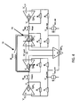
- Figure 1 shows a functional block schematic of partial model of the known dual bridge class SB amplifier.
- Figure 1 is termed a "partial model" because it omits a particular compensation current generator by assuming that the switch 16 resistance is zero.
- Figure 3 an example of dual bridge class SB amplifier having an example implementation of the compensation current generator omitted from the Figure 1 partial model is described.
- the partial model is assumed to receive a system power having a Vdd voltage.
- the absolute value of Vdd is not particular to the embodiments.
- Vdd may for example be +12 volts DC.
- the model includes a first bridge amplifier 12 and a second bridge amplifier 14, switchably connected to one another by a mode switch 16.
- the various criteria and definitions of conditions on which the mode switch 16 is controlled, i.e., opened and closed, are described in greater detail below. Circuitry for generating the signal(s) controlling the mode switch 16 is omitted from Figure 1 because, upon reading the various criteria and conditions on which the mode switch 16 may be controlled, i.e., opened and closed, a person of ordinary skill in the art may readily design and construct a circuit performing the switch control function(s), applying only conventional engineering design knowledge to the present disclosure.
- Figure 1 relates to an example environment having four speakers such as, for example, a front left, a rear left, a front right and a rear right speaker.
- the example of Figure 1 in a complete embodiment such as depicted at Figure 3 may, for example, drive the left front ("FRONT”) and left rear (“REAR") speakers of such a four-speaker example.
- the first bridge amplifier 12 will be referenced hereinafter as the "front” bridge amplifier 12
- the second bridge amplifier 14 will be referenced as the "rear" bridge amplifier 14.
- the front bridge amplifier 12 and the rear bridge amplifier may, but are not necessarily, structurally identical.
- the front bridge amplifier 12 includes a pair of differential amplifiers 18 and 22, the amplifier 18 termed an “inner” differential amplifier 18 and the amplifier 22 termed an “outer” differential amplifier 22.
- the output V1 of the outer differential amplifier 22 connects to one terminal of a front speaker 24.
- the output V2 of the inner differential amplifier 18 connects to the other terminal of the front speaker 24.
- the voltage at the output of the outer differential amplifier 22 is arbitrarily labelled "V1," and the voltage at the output of the inner differential amplifier 18 is arbitrarily labelled "V2" for purposes of reference in further detailed description.
- the outer differential amplifier 22 has a "+” terminal and a "-" terminal.
- the "+” terminal receives an externally generated signal, arbitrarily labelled as Vin_F, which may, for example, be a front fader/splitter (not shown in Figure 1 ) portion of a left channel of a two-channel stereo system (not shown in Figure 1 ).
- Vin_F may, for example, be the above-described example Audio_Front(t).
- the other externally generated signal, Vin_R shown as connected to the "+" input terminal of the outer differential amplifier 36 of the rear bridge amplifier 14, may be an inverted version of Vin_F, i.e., the counterphase of Vin_F
- the Vin_R signal may, for example, be the above-described example Audio_Rear(t) signal.
- Vin_F and Vin_R may or may not have the same magnitude, depending on the setting of, for example, a front-to-rear volume fader.
- Vin_F and Vin_R are not necessarily counterphases of the same signal.
- dual mode class SB amplifiers will provide statistical improvement in the power efficiency.
- the "+" input of amplifier 18 is connected, via connection 19, to the "+” input of the inner differential amplifier 20 of the second, or rear bridge amplifier 14.
- the connection 19 is termed “AC gnd", for reasons that will be readily apparent in view of further detailed descriptions at later sections.
- the "-" input terminal of the inner differential amplifier 18 is connected via feedback resistor 30 to the output of the amplifier and connected, via another feedback resistor 32, to the common node 33.
- the resistors 30 and 32 form a feedback circuit to control the output voltage, labelled V2, of the inner differential amplifier 18.
- the output of the outer differential amplifier 22 connects via feedback resistor 26 to the "-" input of the amplifier 22, and the "-" terminal also connects, through resistor 28, to the common node 33.
- the resistors 26 and 28 therefore form a feedback resistance circuit for the outer differential amplifier 22, and their ratio sets the V2/Vin_F gain.
- Figure 1 shows resistor 26 as having an "R2" value and shows resistor 28 having an "R1" value.
- the R2 value of the resistor 30 may be assumed equal to the R1 value of the resistor 32.
- the absolute resistance values R1 and R2, i.e., the absolute resistance value of resistors 26, 28, 30, and 32 are not particular to the present embodiments. Such values may be readily determined by applying conventional amplifier design methods.
- a front bridge amplifier compensation current source 34 connects to the common node 33, and is configured to feed or sink a current Icom_front to, or from, the common node 33, based on one or the other of Vin_F and Vin_R.
- Icom_front is based on Vin_F and, likewise, the Icom_rear current fed or sunk by the rear bridge compensation circuit 48 is based on Vin_R.
- a result of dual mode class SB amplifiers having the front and rear bridge compensation circuits 34 and 48 configured according to this aspect maintain the voltage Vcom_front at the front common node 33 equal to the voltage Vcom_rear at the rear common node 47 of the rear bridge amplifier 14.
- V2 and V3 are maintained equal to Vdd/2, which is the ACgnd voltage at the connection 19 between the "+" input terminal of the inner differential amplifier 18 of the front bridge amplifier 12 and the "+” input terminal of the inner differential amplifier 20 of the rear bridge amplifier 14.
- the fixed common node voltage embodiments also control the mode switch 16 to open, and thereby switch the dual mode class SB amplifier to the separate amplification mode, when either Vin_F (after being amplified to V1) exceeds Vdd/2, or Vin_R (after being amplified to V4 at the output of the outer differential amplifier 36 of the rear bridge amplifier 14) exceeds Vdd/2.
- the front bridge amplifier compensation current source 34 connected to the front common node 33 sources or sinks, a current Icom_front that is based on the Vin_R signal.
- the rear bridge amplifier compensation current source 48 connected to the rear common node 47 sources or sinks a current Icom_rear that is based on Vin_F.
- V2 is set equal to V3, but at a common voltage that is the average of Vin_F and Vin_R, hence the name "adaptive common node voltage”.
- the rear bridge amplifier 14 is configured identically to the front bridge amplifier 12. More particularly, the output terminal V3 of the inner differential amplifier 20 connects to one terminal of the second load 28. The other terminal of the second load 38 connects to the output terminal V4 of the outer differential amplifier 36. Resistors 40 and 42 form a feedback circuit for the inner differential amplifier 20, connecting the output of the inner differential amplifier 20 to the "-" input of that amplifier 20 and to the common node 47. Resistors 44 and 46 form a feedback circuit connecting the output of the outer differential amplifier 36 to the "-" input terminal of that amplifier 36 and to the common node 47.
- a rear bridge amplifier compensation circuit 48 connects to the common node 47 and is configured to feed or sink a current, Icom_rear, based on one or the other of Vin_F and Vin_R. Further, the given drive signal Vin_R is input to the "+" terminal of the outer differential amplifier 36.
- the purpose of the front and rear bridge amplifier compensation circuits 34 and 48 goal is to keep V2 and V3 constant and equal to each other when the mode switch 16 is closed, placing the front and rear bridge amplifiers 12, 14 in series.
- the only difference between V2 and V3 is the voltage over the mode switch 16, which is caused by the current passing from the output of the inner differential amplifier 18 of the front bridge amplifier 12 to the output of the inner differential amplifier 20 of the rear bridge amplifier 14, or vice versa, multiplied by Rswitch.
- Rswitch should be zero and, for purposes of assisting in focusing the description on the novel aspects of the embodiments, an ideal switch 16 will be assumed.
- the front bridge amplifier compensation circuit 34 and the rear bridge amplifier compensation circuit 48 may be configured to apply the currents Icom_front and Icom_rear, respectively, to the front common node 33 and the rear common node 47:
- Icom_front Vin_F R ⁇ 1 , assuming the resistance of resistor 28 is R ⁇ 1
- Icom_rear Vin_R R ⁇ 1 , assuming the resistance of resistor 46 is R ⁇ 1
- V2 and V3 are constant and equal to AC ground.
- the entire input voltage Vin_F is across the R1 resistance of resistor 28, and the entire input voltage Vin_R is across the same R1 resistance of resistor 46.
- the common output voltage of the amplifiers (virtual mid-tap of the speaker) varies with half the output voltage.
- Vin_max When V1 reaches its maximum value (1 ⁇ 2Vdd), hereinafter referred to as Vin_max, the mode switch 16 must be opened, because the front and rear amplifiers 12, 14 cannot be switched in series anymore and V2 and V3 will become unequal. Now the common output voltage has to go back to AC ground.
- Figure 2 shows an example graphical representation of one example current transfer function, according to the example Equation Nos. 1-4, for controlling the front bridge amplifier compensation circuit 34 and the rear bridge amplifier compensation circuit 48 to source or sink the currents Icom_front and Icom_rear to achieve the necessary values of V2 and V3.
- the horizontal axis 52 represents the voltage Vin relative to the voltage, where "Vin" is Vin_F for referencing the Figure 2 characteristic to the front bridge amplifier compensation circuit 34, and is Vin_R for referencing the Figure 2 characteristic to the rear bridge amplifier compensation circuit 48.
- the vertical axis 54 represents the Icom current with respect to Vin, where "Icom” represents the Icom_front current when referencing Figure 2 characteristic to the front bridge amplifier compensation circuit 34, and represents the Icom_rear current when referencing Figure 2 characteristic to the rear bridge amplifier compensation circuit 48.
- Equation Nos. 1 and 2 apply for the Vin voltage band between points 56 and 58 on Figure 2 , which is the band between negative Vmax/2 and positive Vmax/2. These are the voltages at which mode switch 16 is closed. If Vin is above Vmax/2 or below negative Vmax/2m the mode switch 16 is open. For Vin voltages ranging from negative Vmax/2 to negative Vmax, Equation Nos. 3 and 4 apply, whereupon Icom decreases until Vmas is reached. If Vin goes below Vmax the voltage across at least one of the front and rear speakers will clip. Similarly, for Vin voltages ranging from positive Vmax/2 to positive Vmax Equation Nos. 3 and 4 also apply, and Icom decreases until Vmax is reached, beyond which the amplifier clips. If Vin goes above Vmax, the voltage across at least one of the front and rear speakers will clip.
- V2 and V3 must have a difference equal to the current passing through the mode switch 16 multiplied by Rswitch. If this difference is not provided, the current cannot flow. Further, if V2 and V3 are set to correspond to the voltage drop across the mode switch 16 then, as discovered by the present inventors, the currents sourced or sunk by the inner differential amplifiers 18 and 20 will have the same magnitude, and be in the same direction. Based on this information, the following two example means may be used to control V2 and V3.
- the first is a feedforward control such as, for example, calculating the required V2 and V3 and feeding this forward, for example, to the inner differential amplifiers 18 and 20.
- the second is a feedback control, implemented by, for example, detecting the current output (or sunk) by each of the inner differential amplifiers 18 and 20 and, based on the detected difference, source or sink an additional compensation current to the front common node 33 and the rear common node 47.
- Figure 3 shows one example dual bridge switched SB amplifier according to one or more embodiments, having one example implementation of an exemplary switch voltage control circuit according to one feedback-type switch voltage control aspect for controlling V2 and V3 as previously described. It will be understood that the Figure 3 example is depicted as a modification of the Figure 1 partial model and, therefore, like components and features are labelled with like reference numbers.
- zero current should flow between the inner differential amplifiers 18 and 20 because, if this condition can be guaranteed, the current that is able to be shared between the front and the rear speakers 24, 28 will flow through the mode switch 16.
- One example means to guarantee the above-described condition is to measure the output currents of the inner differential amplifiers 18 and 20. Such measurement can be done by means of, for example, a scaled duplicate of these output currents.
- the common amplifier 62 based on detecting the currents 64 and 66 of the inner differential amplifiers 18 and 20, outputs currents 68R and 68F, which forces the amplifiers' respective output currents to flow in the same direction, because current will flow through the mode switch 16 due to the change in the common mode voltages V2 and V3.
- the resistance of the amplifiers remains low because the loads, e.g., the front load 24 and rear load 28 are voltage driven. Resistance of the mode switch 16 is not located in the signal path.
- the additional control loop 62, 64, 66, 68F and 68R only affects the common mode voltages because it is not in the signal path and, as previously described, the control loop also compensates for inaccuracy of the compensation currents Icom_front and Icom_rear generated by the front and rear compensation current sources 34 and 48.
- the voltage V2 and V3 may be made adaptive such that a dual mode class SB amplifier according to one or more embodiments may be maintained in the series amplification mode for a higher percentage of time, or at a higher statistical probability.
- this feature is obtained by adapting the common mode output voltage, i.e., V2 and V3 in the depicted example, to both of the input signals Vin_F and VinR.
- One example implementation according to this one aspect is to modify the Figure 3 version, as well as its included partial model, by applying different common currents at the tails than described by Equation Nos. 1-4 and depicted at Figure 2 .
- the generated Icom_front and Icom_rear currents are feedforward currents, which are generated in relation to Vin as shown in Figure 2 .
- the amplifier Gm5 is an additional feedback control needed to keep currents from Gm2 and Gm3 flowing in the same direction. In this way, the shared signal current is forced through the switch. This means a current will flow through the switch due to a common mode offset between two the BTL amplifiers.
- the current is derived that must be applied to the tail of the bridge tied load in order to keep V2 and V3 constant.
- the system decides to close the switch between stages Gm2 and Gm3 while, due to the delay, they are still at either supply or ground.
- the maximum cross-current is in the range of Vsupply/(Rswitch+RON,gm2+RON,gm3).
- the typical switch resistance is in the range of ohms, (for example around 0.1 Ohm) the current is mainly determined by the value of Rswitch. This means that given a certain switch resistance, cross-currents will be increase for increasing values of Vsupply.
- Figure 4 shows an example of two clipping BTL amplifiers where the output of Gm2 is at ground level and the output of Gm3 is at supply voltage level.
- the system decides to close the switch based on the feed-forward control, this results in a large cross current as shown by the arrow 70.
- Figure 5 shows the signals of a non-clipping BTL channel and Figure 6 shows the delay introduced when a BTL channel is clipping. As shown schematically, the signals in Figure 6 are larger to represent clipping. The delay following an input voltage change is shown in Figure 6 .
- the invention aims to prevent large currents in the system caused by the delay introduced in the output stages resulting from the feed forward based control of the switch.
- the invention is based on detecting if the outputs are still clipping, and then preventing the mode switch from being closed.
- Clipping of the outputs can be detected in following ways:
- the circuit is shown in Figure 7 . Only the relevant parts of the known circuit of Figure 1 are shown (the four amplifiers Gm1 to Gm4, the mode switch and the two loads).
- a clip detection circuit comprises two clip detection units 71,72 for detecting if the outputs connected to the switch (nodes V2 and V3) are clipping.
- the two clip detectors 71,72 detect high-side and low-side clipping of the outputs connected to the switch.
- the clip detect signals are combined with a logic OR gate 74 and then a delay is added by delay unit 76.
- the delay is added to introduce filtering of glitches and to add a safety margin before closing the mode switch after the output recovers from clipping.
- the threshold levels of the clip detect circuits 71,72 should be such that they are above the worst-case voltage drop over the power transistor during all use-case conditions (such as high temp, high current, process spread).
- the timing of the delay filter is in of order of a few micro-seconds, such as between 1 and 10 microseconds.
- a 20kHz maximum frequency for an audio signal corresponds to a period of 50 microseconds.
- Timing considerations are that the delay should be low enough to guarantee no interference in the worst-case operating conditions.
- the system is designed using soft-switching to improve total harmonic distortion ("THD") performance. When the switch closes too late, it can cause abrupt switching compromising THD.
- the delay should also be high enough to allow some filtering for glitches and have sufficient safety margin.
- Figure 8 shows simulation results of a Class-SB configuration without the improvement of the invention, during a clipping condition at a typical supply voltage of 14.4V.
- the top two plots show the two pairs of differential outputs V1,V2 and V3,V4.
- the fourth plot shows the current flowing through the mode switch Iswitch.
- a high cross-current spike 80 can be seen of more than 6A through the switch at the moment the full supply-voltage is over the switch. This cross current is superimposed on the already high supply current. The switch shorts V2 and V3 causing them to be forced to one another.
- Figure 9 shows the same simulation but using the circuit of Figure 3 . No large cross-currents through the mode switch are present.
- Figure 10 shows the voltages at the mode switch (V2 and V3).
- the voltage Vclip at the output of the OR gate 54 goes high. This signal is delayed by the delay 76 to generate the voltage Vcipdelay.
- the voltage Vclipdelay is provided to the control logic 78 and as long as Vclipdelay is high the switch is prevented from being closed.
- the invention can be used in audio amplifiers such as automotive audio amplifiers using the Class-SB high efficiency principle.
- the amplifier is a high efficiency quad class-AB amplifier with full diagnostics.
Landscapes
- Engineering & Computer Science (AREA)
- Power Engineering (AREA)
- Multimedia (AREA)
- Microelectronics & Electronic Packaging (AREA)
- Physics & Mathematics (AREA)
- Acoustics & Sound (AREA)
- Signal Processing (AREA)
- Amplifiers (AREA)
Claims (15)
- Amplificateur comprenant :- une première section d'amplificateur de pont (12) comprenant deux amplificateurs différentiels (18, 22) avec une première charge connectée entre leurs sorties ;- une seconde section d'amplificateur de pont (14) comportant deux amplificateurs différentiels (20, 36) avec une seconde charge connectée entre leurs sorties ;- un commutateur de mode (16) entre une première sortie d'un amplificateur différentiel de la première section d'amplificateur de pont et une seconde sortie d'un amplificateur différentiel de la seconde section d'amplificateur de pont ;- un circuit de commande (78) afin de commander le commutateur de mode en fonction de signaux d'entrée (in+, in-) vers les première et seconde sections d'amplificateur de pont ;- un système de détection de distorsion (71, 72) afin de détecter une distorsion dans les première ou seconde sorties ; et- un retardateur (76) afin de fournir une période de retard à partir du moment où la distorsion est détectée ;dans lequel le circuit de commande empêche la fermeture du commutateur de mode pendant la période de retard.
- Amplificateur selon la revendication 1, comprenant un amplificateur audio.
- Amplificateur selon l'une quelconque des revendications précédentes, comprenant une première queue de source de courant (34) pour la première section d'amplificateur de pont et une seconde queue de source de courant (48) pour la seconde section d'amplificateur de pont.
- Amplificateur selon la revendication 3, comprenant un amplificateur (62) qui détecte des courants d'un amplificateur différentiel de sortie de la première section d'amplificateur de pont et d'un amplificateur différentiel de sortie de la seconde section d'amplificateur de pont afin de générer des courants de sortie qui forcent les courants de sortie des amplificateurs différentiels de sortie à s'écouler dans la même direction.
- Amplificateur selon l'une quelconque des revendications précédentes, dans lequel le système de détection de distorsion (71, 72) comprend un moyen pour mesurer la tension de la sortie par rapport à la terre ou une tension d'alimentation.
- Amplificateur selon l'une quelconque des revendications précédentes, dans lequel le système de détection de distorsion est conçu pour détecter une distorsion côté haut et une distorsion côté bas des signaux de chaque côté du commutateur de mode (16).
- Amplificateur selon la revendication 6, comprenant en outre une grille OU logique (74) afin de combiner les signaux de distorsion de chaque côté du commutateur de mode (16) et fournir le signal combiné au retardateur (76).
- Amplificateur selon l'une quelconque des revendications précédentes, dans lequel la période de retard a une valeur de 1 à 10 microsecondes.
- Circuit de haut-parleur comprenant un amplificateur selon l'une quelconque des revendications précédentes, un premier haut-parleur qui comprend la première charge et un second haut-parleur qui comprend la seconde charge.
- Procédé de commande d'un amplificateur, lequel amplificateur comprend :- une première section d'amplificateur de pont (12) comprenant deux amplificateurs différentiels avec une première charge connectée entre leurs sorties ;- une seconde section d'amplificateur de pont (14) comportant deux amplificateurs différentiels avec une seconde charge connectée entre leurs sorties ;- un commutateur de mode (16) entre une première sortie d'un amplificateur différentiel de la première section d'amplificateur de pont et une seconde sortie d'un amplificateur différentiel de la seconde section d'amplificateur de pont ;lequel procédé consiste à :- commander le commutateur de mode (16) en fonction de signaux d'entrée vers les première et seconde sections d'amplificateur de pont ;- détecter une distorsion dans les première ou seconde sorties ; et- empêcher la fermeture du commutateur de mode pendant une période de retard à partir du moment où la distorsion est détectée.
- Procédé selon la revendication 10, consistant à détecter des courants d'un amplificateur différentiel de sortie de la première section d'amplificateur de pont et d'un amplificateur différentiel de sortie de la seconde section d'amplificateur de pont afin de générer ainsi des courants de sortie qui forcent les courants de sortie des amplificateurs différentiels de sortie à s'écouler dans la même direction.
- Procédé selon les revendications 10 ou 11, dans lequel la détection de la distorsion consiste à mesurer la tension de la sortie par rapport à la terre ou une tension d'alimentation.
- Procédé selon les revendications 10, 11 ou 12, dans lequel la détection de la distorsion consiste à détecter une distorsion côté haut et une distorsion côté bas des signaux de chaque côté du commutateur de mode.
- Procédé selon l'une quelconque des revendications 10 à 14, dans lequel la période de retard a une valeur de 1 à 10 microsecondes.
- Procédé selon l'une quelconque des revendications 10 à 14, permettant d'actionner un premier haut-parleur qui comprend la première charge, et un second haut-parleur qui comprend la seconde charge.
Priority Applications (3)
| Application Number | Priority Date | Filing Date | Title |
|---|---|---|---|
| EP13167116.6A EP2802076B1 (fr) | 2013-05-08 | 2013-05-08 | Configuration d'amplificateur à double pont |
| US14/268,135 US9385670B2 (en) | 2013-05-08 | 2014-05-02 | Dual bridge amplifier configuration |
| CN201410190488.9A CN104143963B (zh) | 2013-05-08 | 2014-05-07 | 双桥放大器结构 |
Applications Claiming Priority (1)
| Application Number | Priority Date | Filing Date | Title |
|---|---|---|---|
| EP13167116.6A EP2802076B1 (fr) | 2013-05-08 | 2013-05-08 | Configuration d'amplificateur à double pont |
Publications (2)
| Publication Number | Publication Date |
|---|---|
| EP2802076A1 EP2802076A1 (fr) | 2014-11-12 |
| EP2802076B1 true EP2802076B1 (fr) | 2015-11-18 |
Family
ID=48236794
Family Applications (1)
| Application Number | Title | Priority Date | Filing Date |
|---|---|---|---|
| EP13167116.6A Active EP2802076B1 (fr) | 2013-05-08 | 2013-05-08 | Configuration d'amplificateur à double pont |
Country Status (3)
| Country | Link |
|---|---|
| US (1) | US9385670B2 (fr) |
| EP (1) | EP2802076B1 (fr) |
| CN (1) | CN104143963B (fr) |
Families Citing this family (1)
| Publication number | Priority date | Publication date | Assignee | Title |
|---|---|---|---|---|
| CN113783532A (zh) | 2020-06-10 | 2021-12-10 | 武汉杰开科技有限公司 | 一种功率放大器及其控制方法、车载音频系统 |
Family Cites Families (7)
| Publication number | Priority date | Publication date | Assignee | Title |
|---|---|---|---|---|
| EP0613242B1 (fr) * | 1993-02-24 | 1997-10-29 | STMicroelectronics S.r.l. | Amplificateur à double pont, auto-configurable |
| DE69429660T2 (de) * | 1994-10-07 | 2002-11-14 | Stmicroelectronics S.R.L., Agrate Brianza | Brückenverstärker mit hohem Wirkungsgrad |
| DE19525410A1 (de) * | 1995-07-12 | 1997-01-23 | Philips Patentverwaltung | Schaltungsanordnung zum Übertragen von Tonsignalen |
| DE19525411A1 (de) | 1995-07-12 | 1997-01-16 | Philips Patentverwaltung | Signalverstärker |
| EP1496611A1 (fr) * | 2003-07-09 | 2005-01-12 | STMicroelectronics S.r.l. | Amplificateur multicanal de puissance à configuration automatique asymétrique ou en pont, en particulier pour applications audio |
| EP1548933B1 (fr) * | 2003-12-23 | 2007-11-28 | STMicroelectronics S.r.l. | Méthode pour la prévention des variations de tension abruptes à la sortie d'une paire de circuits d'amplificateur et circuit de régulation pour une paire de circuits d'amplificateur à autoconfiguration dans une configuration en pont |
| US8330539B2 (en) * | 2009-08-14 | 2012-12-11 | Nxp B.V. | Dynamic switchable mode dual bridge power amplifier |
-
2013
- 2013-05-08 EP EP13167116.6A patent/EP2802076B1/fr active Active
-
2014
- 2014-05-02 US US14/268,135 patent/US9385670B2/en active Active
- 2014-05-07 CN CN201410190488.9A patent/CN104143963B/zh active Active
Also Published As
| Publication number | Publication date |
|---|---|
| US9385670B2 (en) | 2016-07-05 |
| CN104143963B (zh) | 2017-05-10 |
| CN104143963A (zh) | 2014-11-12 |
| EP2802076A1 (fr) | 2014-11-12 |
| US20140334647A1 (en) | 2014-11-13 |
Similar Documents
| Publication | Publication Date | Title |
|---|---|---|
| US8723605B2 (en) | Efficient power amplifier | |
| CN101911479B (zh) | 差分放大器系统 | |
| US8674765B2 (en) | Fully differential amplifier topology to drive dynamic speakers in class AB mode | |
| JP2017529791A5 (fr) | ||
| US8502602B2 (en) | Class-D amplifier circuit | |
| US20150214902A1 (en) | Device and method for reducing clipping in an amplifier | |
| EP2284993B1 (fr) | Amplificateur d'alimentation de pont à double mode commutable dynamique | |
| US9602070B2 (en) | Power amplifying device | |
| KR20160007370A (ko) | 클래스 ab 오디오 증폭기 출력단 전압 보호 방법 및 장치 | |
| US9559648B2 (en) | Amplifier with reduced idle power loss using single-ended loops | |
| JP2005286815A (ja) | 電力増幅器 | |
| US8841965B2 (en) | Amplifier | |
| CN103929137A (zh) | 一种连续调节d类功放功率的电路及其功率调节方法 | |
| EP2802076B1 (fr) | Configuration d'amplificateur à double pont | |
| JP5502719B2 (ja) | 負荷装置 | |
| WO2017051490A1 (fr) | Nœud de communication | |
| US10256776B1 (en) | Steered current source for single-ended class-A amplifier | |
| US10367458B2 (en) | Signal amplifier | |
| JP5343782B2 (ja) | D級増幅器 | |
| GB2592877A (en) | Inverter-based differential amplifier | |
| US9281789B2 (en) | Integrated circuit for use in a hybrid output stage | |
| JP2009089289A (ja) | D級増幅器 | |
| WO2022264716A1 (fr) | Amplificateur haute tension | |
| JP2011211389A (ja) | 増幅回路、増幅回路のクリップ検出方法 | |
| KR20130032526A (ko) | 전력 증폭기 |
Legal Events
| Date | Code | Title | Description |
|---|---|---|---|
| PUAI | Public reference made under article 153(3) epc to a published international application that has entered the european phase |
Free format text: ORIGINAL CODE: 0009012 |
|
| 17P | Request for examination filed |
Effective date: 20140326 |
|
| AK | Designated contracting states |
Kind code of ref document: A1 Designated state(s): AL AT BE BG CH CY CZ DE DK EE ES FI FR GB GR HR HU IE IS IT LI LT LU LV MC MK MT NL NO PL PT RO RS SE SI SK SM TR |
|
| AX | Request for extension of the european patent |
Extension state: BA ME |
|
| GRAP | Despatch of communication of intention to grant a patent |
Free format text: ORIGINAL CODE: EPIDOSNIGR1 |
|
| RIC1 | Information provided on ipc code assigned before grant |
Ipc: H03F 3/45 20060101ALI20150303BHEP Ipc: H03F 3/185 20060101ALI20150303BHEP Ipc: H04R 1/00 20060101ALI20150303BHEP Ipc: H03F 3/68 20060101AFI20150303BHEP Ipc: H03F 3/217 20060101ALI20150303BHEP Ipc: H03F 3/187 20060101ALI20150303BHEP Ipc: H03F 1/52 20060101ALI20150303BHEP |
|
| INTG | Intention to grant announced |
Effective date: 20150319 |
|
| RBV | Designated contracting states (corrected) |
Designated state(s): AL AT BE BG CH CY CZ DE DK EE ES FI FR GB GR HR HU IE IS IT LI LT LU LV MC MK MT NL NO PL PT RO RS SE SI SK SM TR |
|
| GRAP | Despatch of communication of intention to grant a patent |
Free format text: ORIGINAL CODE: EPIDOSNIGR1 |
|
| INTG | Intention to grant announced |
Effective date: 20150813 |
|
| RIN1 | Information on inventor provided before grant (corrected) |
Inventor name: MARTIN, MAX Inventor name: MOSTERT, FRED Inventor name: HISSINK, DERK-JAN |
|
| GRAS | Grant fee paid |
Free format text: ORIGINAL CODE: EPIDOSNIGR3 |
|
| GRAA | (expected) grant |
Free format text: ORIGINAL CODE: 0009210 |
|
| AK | Designated contracting states |
Kind code of ref document: B1 Designated state(s): AL AT BE BG CH CY CZ DE DK EE ES FI FR GB GR HR HU IE IS IT LI LT LU LV MC MK MT NL NO PL PT RO RS SE SI SK SM TR |
|
| REG | Reference to a national code |
Ref country code: GB Ref legal event code: FG4D |
|
| REG | Reference to a national code |
Ref country code: CH Ref legal event code: EP |
|
| REG | Reference to a national code |
Ref country code: AT Ref legal event code: REF Ref document number: 761994 Country of ref document: AT Kind code of ref document: T Effective date: 20151215 |
|
| REG | Reference to a national code |
Ref country code: IE Ref legal event code: FG4D |
|
| REG | Reference to a national code |
Ref country code: DE Ref legal event code: R096 Ref document number: 602013003822 Country of ref document: DE |
|
| REG | Reference to a national code |
Ref country code: NL Ref legal event code: MP Effective date: 20160218 |
|
| REG | Reference to a national code |
Ref country code: LT Ref legal event code: MG4D |
|
| REG | Reference to a national code |
Ref country code: AT Ref legal event code: MK05 Ref document number: 761994 Country of ref document: AT Kind code of ref document: T Effective date: 20151118 |
|
| REG | Reference to a national code |
Ref country code: FR Ref legal event code: PLFP Year of fee payment: 4 |
|
| PG25 | Lapsed in a contracting state [announced via postgrant information from national office to epo] |
Ref country code: IT Free format text: LAPSE BECAUSE OF FAILURE TO SUBMIT A TRANSLATION OF THE DESCRIPTION OR TO PAY THE FEE WITHIN THE PRESCRIBED TIME-LIMIT Effective date: 20151118 Ref country code: HR Free format text: LAPSE BECAUSE OF FAILURE TO SUBMIT A TRANSLATION OF THE DESCRIPTION OR TO PAY THE FEE WITHIN THE PRESCRIBED TIME-LIMIT Effective date: 20151118 Ref country code: LT Free format text: LAPSE BECAUSE OF FAILURE TO SUBMIT A TRANSLATION OF THE DESCRIPTION OR TO PAY THE FEE WITHIN THE PRESCRIBED TIME-LIMIT Effective date: 20151118 Ref country code: NL Free format text: LAPSE BECAUSE OF FAILURE TO SUBMIT A TRANSLATION OF THE DESCRIPTION OR TO PAY THE FEE WITHIN THE PRESCRIBED TIME-LIMIT Effective date: 20151118 Ref country code: ES Free format text: LAPSE BECAUSE OF FAILURE TO SUBMIT A TRANSLATION OF THE DESCRIPTION OR TO PAY THE FEE WITHIN THE PRESCRIBED TIME-LIMIT Effective date: 20151118 Ref country code: IS Free format text: LAPSE BECAUSE OF FAILURE TO SUBMIT A TRANSLATION OF THE DESCRIPTION OR TO PAY THE FEE WITHIN THE PRESCRIBED TIME-LIMIT Effective date: 20160318 Ref country code: NO Free format text: LAPSE BECAUSE OF FAILURE TO SUBMIT A TRANSLATION OF THE DESCRIPTION OR TO PAY THE FEE WITHIN THE PRESCRIBED TIME-LIMIT Effective date: 20160218 |
|
| PG25 | Lapsed in a contracting state [announced via postgrant information from national office to epo] |
Ref country code: RS Free format text: LAPSE BECAUSE OF FAILURE TO SUBMIT A TRANSLATION OF THE DESCRIPTION OR TO PAY THE FEE WITHIN THE PRESCRIBED TIME-LIMIT Effective date: 20151118 Ref country code: SE Free format text: LAPSE BECAUSE OF FAILURE TO SUBMIT A TRANSLATION OF THE DESCRIPTION OR TO PAY THE FEE WITHIN THE PRESCRIBED TIME-LIMIT Effective date: 20151118 Ref country code: LV Free format text: LAPSE BECAUSE OF FAILURE TO SUBMIT A TRANSLATION OF THE DESCRIPTION OR TO PAY THE FEE WITHIN THE PRESCRIBED TIME-LIMIT Effective date: 20151118 Ref country code: PT Free format text: LAPSE BECAUSE OF FAILURE TO SUBMIT A TRANSLATION OF THE DESCRIPTION OR TO PAY THE FEE WITHIN THE PRESCRIBED TIME-LIMIT Effective date: 20160318 Ref country code: FI Free format text: LAPSE BECAUSE OF FAILURE TO SUBMIT A TRANSLATION OF THE DESCRIPTION OR TO PAY THE FEE WITHIN THE PRESCRIBED TIME-LIMIT Effective date: 20151118 Ref country code: PL Free format text: LAPSE BECAUSE OF FAILURE TO SUBMIT A TRANSLATION OF THE DESCRIPTION OR TO PAY THE FEE WITHIN THE PRESCRIBED TIME-LIMIT Effective date: 20151118 Ref country code: AT Free format text: LAPSE BECAUSE OF FAILURE TO SUBMIT A TRANSLATION OF THE DESCRIPTION OR TO PAY THE FEE WITHIN THE PRESCRIBED TIME-LIMIT Effective date: 20151118 |
|
| PG25 | Lapsed in a contracting state [announced via postgrant information from national office to epo] |
Ref country code: CZ Free format text: LAPSE BECAUSE OF FAILURE TO SUBMIT A TRANSLATION OF THE DESCRIPTION OR TO PAY THE FEE WITHIN THE PRESCRIBED TIME-LIMIT Effective date: 20151118 |
|
| REG | Reference to a national code |
Ref country code: DE Ref legal event code: R097 Ref document number: 602013003822 Country of ref document: DE |
|
| PG25 | Lapsed in a contracting state [announced via postgrant information from national office to epo] |
Ref country code: RO Free format text: LAPSE BECAUSE OF FAILURE TO SUBMIT A TRANSLATION OF THE DESCRIPTION OR TO PAY THE FEE WITHIN THE PRESCRIBED TIME-LIMIT Effective date: 20151118 Ref country code: DK Free format text: LAPSE BECAUSE OF FAILURE TO SUBMIT A TRANSLATION OF THE DESCRIPTION OR TO PAY THE FEE WITHIN THE PRESCRIBED TIME-LIMIT Effective date: 20151118 Ref country code: SK Free format text: LAPSE BECAUSE OF FAILURE TO SUBMIT A TRANSLATION OF THE DESCRIPTION OR TO PAY THE FEE WITHIN THE PRESCRIBED TIME-LIMIT Effective date: 20151118 Ref country code: BE Free format text: LAPSE BECAUSE OF NON-PAYMENT OF DUE FEES Effective date: 20160531 Ref country code: EE Free format text: LAPSE BECAUSE OF FAILURE TO SUBMIT A TRANSLATION OF THE DESCRIPTION OR TO PAY THE FEE WITHIN THE PRESCRIBED TIME-LIMIT Effective date: 20151118 Ref country code: SM Free format text: LAPSE BECAUSE OF FAILURE TO SUBMIT A TRANSLATION OF THE DESCRIPTION OR TO PAY THE FEE WITHIN THE PRESCRIBED TIME-LIMIT Effective date: 20151118 |
|
| PLBE | No opposition filed within time limit |
Free format text: ORIGINAL CODE: 0009261 |
|
| STAA | Information on the status of an ep patent application or granted ep patent |
Free format text: STATUS: NO OPPOSITION FILED WITHIN TIME LIMIT |
|
| 26N | No opposition filed |
Effective date: 20160819 |
|
| PG25 | Lapsed in a contracting state [announced via postgrant information from national office to epo] |
Ref country code: SI Free format text: LAPSE BECAUSE OF FAILURE TO SUBMIT A TRANSLATION OF THE DESCRIPTION OR TO PAY THE FEE WITHIN THE PRESCRIBED TIME-LIMIT Effective date: 20151118 |
|
| PG25 | Lapsed in a contracting state [announced via postgrant information from national office to epo] |
Ref country code: BE Free format text: LAPSE BECAUSE OF FAILURE TO SUBMIT A TRANSLATION OF THE DESCRIPTION OR TO PAY THE FEE WITHIN THE PRESCRIBED TIME-LIMIT Effective date: 20151118 Ref country code: LU Free format text: LAPSE BECAUSE OF FAILURE TO SUBMIT A TRANSLATION OF THE DESCRIPTION OR TO PAY THE FEE WITHIN THE PRESCRIBED TIME-LIMIT Effective date: 20160508 |
|
| REG | Reference to a national code |
Ref country code: CH Ref legal event code: PL |
|
| PG25 | Lapsed in a contracting state [announced via postgrant information from national office to epo] |
Ref country code: CH Free format text: LAPSE BECAUSE OF NON-PAYMENT OF DUE FEES Effective date: 20160531 Ref country code: LI Free format text: LAPSE BECAUSE OF NON-PAYMENT OF DUE FEES Effective date: 20160531 |
|
| REG | Reference to a national code |
Ref country code: IE Ref legal event code: MM4A |
|
| REG | Reference to a national code |
Ref country code: FR Ref legal event code: PLFP Year of fee payment: 5 |
|
| PG25 | Lapsed in a contracting state [announced via postgrant information from national office to epo] |
Ref country code: IE Free format text: LAPSE BECAUSE OF NON-PAYMENT OF DUE FEES Effective date: 20160508 |
|
| REG | Reference to a national code |
Ref country code: FR Ref legal event code: PLFP Year of fee payment: 6 |
|
| PG25 | Lapsed in a contracting state [announced via postgrant information from national office to epo] |
Ref country code: HU Free format text: LAPSE BECAUSE OF FAILURE TO SUBMIT A TRANSLATION OF THE DESCRIPTION OR TO PAY THE FEE WITHIN THE PRESCRIBED TIME-LIMIT; INVALID AB INITIO Effective date: 20130508 |
|
| PG25 | Lapsed in a contracting state [announced via postgrant information from national office to epo] |
Ref country code: GR Free format text: LAPSE BECAUSE OF FAILURE TO SUBMIT A TRANSLATION OF THE DESCRIPTION OR TO PAY THE FEE WITHIN THE PRESCRIBED TIME-LIMIT Effective date: 20151118 Ref country code: MC Free format text: LAPSE BECAUSE OF FAILURE TO SUBMIT A TRANSLATION OF THE DESCRIPTION OR TO PAY THE FEE WITHIN THE PRESCRIBED TIME-LIMIT Effective date: 20151118 Ref country code: MT Free format text: LAPSE BECAUSE OF NON-PAYMENT OF DUE FEES Effective date: 20160531 Ref country code: MK Free format text: LAPSE BECAUSE OF FAILURE TO SUBMIT A TRANSLATION OF THE DESCRIPTION OR TO PAY THE FEE WITHIN THE PRESCRIBED TIME-LIMIT Effective date: 20151118 Ref country code: CY Free format text: LAPSE BECAUSE OF FAILURE TO SUBMIT A TRANSLATION OF THE DESCRIPTION OR TO PAY THE FEE WITHIN THE PRESCRIBED TIME-LIMIT Effective date: 20151118 |
|
| PG25 | Lapsed in a contracting state [announced via postgrant information from national office to epo] |
Ref country code: BG Free format text: LAPSE BECAUSE OF FAILURE TO SUBMIT A TRANSLATION OF THE DESCRIPTION OR TO PAY THE FEE WITHIN THE PRESCRIBED TIME-LIMIT Effective date: 20151118 |
|
| PG25 | Lapsed in a contracting state [announced via postgrant information from national office to epo] |
Ref country code: AL Free format text: LAPSE BECAUSE OF FAILURE TO SUBMIT A TRANSLATION OF THE DESCRIPTION OR TO PAY THE FEE WITHIN THE PRESCRIBED TIME-LIMIT Effective date: 20151118 Ref country code: TR Free format text: LAPSE BECAUSE OF FAILURE TO SUBMIT A TRANSLATION OF THE DESCRIPTION OR TO PAY THE FEE WITHIN THE PRESCRIBED TIME-LIMIT Effective date: 20151118 |
|
| P01 | Opt-out of the competence of the unified patent court (upc) registered |
Effective date: 20230725 |
|
| PGFP | Annual fee paid to national office [announced via postgrant information from national office to epo] |
Ref country code: GB Payment date: 20240418 Year of fee payment: 12 |
|
| PGFP | Annual fee paid to national office [announced via postgrant information from national office to epo] |
Ref country code: DE Payment date: 20240418 Year of fee payment: 12 |
|
| PGFP | Annual fee paid to national office [announced via postgrant information from national office to epo] |
Ref country code: FR Payment date: 20240418 Year of fee payment: 12 |