EP2801846A1 - Élément optique doté d'un revêtement à haute diffusivité - Google Patents
Élément optique doté d'un revêtement à haute diffusivité Download PDFInfo
- Publication number
- EP2801846A1 EP2801846A1 EP14163993.0A EP14163993A EP2801846A1 EP 2801846 A1 EP2801846 A1 EP 2801846A1 EP 14163993 A EP14163993 A EP 14163993A EP 2801846 A1 EP2801846 A1 EP 2801846A1
- Authority
- EP
- European Patent Office
- Prior art keywords
- coating
- substrate body
- layer
- optical element
- hardcoat
- Prior art date
- Legal status (The legal status is an assumption and is not a legal conclusion. Google has not performed a legal analysis and makes no representation as to the accuracy of the status listed.)
- Granted
Links
- 238000000576 coating method Methods 0.000 title claims abstract description 150
- 239000011248 coating agent Substances 0.000 title claims abstract description 145
- 230000003287 optical effect Effects 0.000 title claims abstract description 102
- 238000009792 diffusion process Methods 0.000 title description 6
- 239000000758 substrate Substances 0.000 claims abstract description 120
- XLYOFNOQVPJJNP-UHFFFAOYSA-N water Substances O XLYOFNOQVPJJNP-UHFFFAOYSA-N 0.000 claims abstract description 53
- 239000004033 plastic Substances 0.000 claims abstract description 28
- 229920003023 plastic Polymers 0.000 claims abstract description 28
- 230000003595 spectral effect Effects 0.000 claims abstract description 9
- 239000004922 lacquer Substances 0.000 claims abstract description 6
- 239000000203 mixture Substances 0.000 claims description 23
- 239000002245 particle Substances 0.000 claims description 19
- 239000011148 porous material Substances 0.000 claims description 18
- 239000000126 substance Substances 0.000 claims description 18
- 239000002105 nanoparticle Substances 0.000 claims description 16
- 239000000654 additive Substances 0.000 claims description 12
- 230000000996 additive effect Effects 0.000 claims description 12
- 238000012360 testing method Methods 0.000 claims description 12
- 229910004298 SiO 2 Inorganic materials 0.000 claims description 9
- VYPSYNLAJGMNEJ-UHFFFAOYSA-N silicon dioxide Inorganic materials O=[Si]=O VYPSYNLAJGMNEJ-UHFFFAOYSA-N 0.000 claims description 7
- 238000010849 ion bombardment Methods 0.000 claims description 6
- 239000010453 quartz Substances 0.000 claims description 6
- 125000004429 atom Chemical group 0.000 claims description 5
- 229910018072 Al 2 O 3 Inorganic materials 0.000 claims description 4
- 238000004519 manufacturing process Methods 0.000 claims description 4
- 125000004432 carbon atom Chemical group C* 0.000 claims description 3
- PCHJSUWPFVWCPO-UHFFFAOYSA-N gold Chemical group [Au] PCHJSUWPFVWCPO-UHFFFAOYSA-N 0.000 claims description 3
- 229910052756 noble gas Inorganic materials 0.000 claims description 3
- 238000007639 printing Methods 0.000 claims description 2
- 238000005019 vapor deposition process Methods 0.000 claims description 2
- 239000010410 layer Substances 0.000 description 151
- 239000000463 material Substances 0.000 description 26
- 239000003570 air Substances 0.000 description 19
- 150000002500 ions Chemical class 0.000 description 19
- 239000007789 gas Substances 0.000 description 15
- XKRFYHLGVUSROY-UHFFFAOYSA-N Argon Chemical compound [Ar] XKRFYHLGVUSROY-UHFFFAOYSA-N 0.000 description 12
- 238000000034 method Methods 0.000 description 11
- 239000006117 anti-reflective coating Substances 0.000 description 8
- QVGXLLKOCUKJST-UHFFFAOYSA-N atomic oxygen Chemical compound [O] QVGXLLKOCUKJST-UHFFFAOYSA-N 0.000 description 7
- 238000010894 electron beam technology Methods 0.000 description 7
- 239000011521 glass Substances 0.000 description 7
- 239000001301 oxygen Substances 0.000 description 7
- 229910052760 oxygen Inorganic materials 0.000 description 7
- 229910052786 argon Inorganic materials 0.000 description 6
- 239000012535 impurity Substances 0.000 description 6
- 238000006748 scratching Methods 0.000 description 5
- 230000002393 scratching effect Effects 0.000 description 5
- IJGRMHOSHXDMSA-UHFFFAOYSA-N Atomic nitrogen Chemical compound N#N IJGRMHOSHXDMSA-UHFFFAOYSA-N 0.000 description 4
- 229910010413 TiO 2 Inorganic materials 0.000 description 4
- 230000008901 benefit Effects 0.000 description 4
- 230000000694 effects Effects 0.000 description 4
- 238000012986 modification Methods 0.000 description 4
- 230000004048 modification Effects 0.000 description 4
- 238000005240 physical vapour deposition Methods 0.000 description 4
- 229920000642 polymer Polymers 0.000 description 4
- 229920001296 polysiloxane Polymers 0.000 description 4
- OGIDPMRJRNCKJF-UHFFFAOYSA-N titanium oxide Inorganic materials [Ti]=O OGIDPMRJRNCKJF-UHFFFAOYSA-N 0.000 description 4
- LYCAIKOWRPUZTN-UHFFFAOYSA-N Ethylene glycol Chemical compound OCCO LYCAIKOWRPUZTN-UHFFFAOYSA-N 0.000 description 3
- GWEVSGVZZGPLCZ-UHFFFAOYSA-N Titan oxide Chemical compound O=[Ti]=O GWEVSGVZZGPLCZ-UHFFFAOYSA-N 0.000 description 3
- 238000010521 absorption reaction Methods 0.000 description 3
- PNEYBMLMFCGWSK-UHFFFAOYSA-N aluminium oxide Inorganic materials [O-2].[O-2].[O-2].[Al+3].[Al+3] PNEYBMLMFCGWSK-UHFFFAOYSA-N 0.000 description 3
- 230000007547 defect Effects 0.000 description 3
- JEGUKCSWCFPDGT-UHFFFAOYSA-N h2o hydrate Chemical compound O.O JEGUKCSWCFPDGT-UHFFFAOYSA-N 0.000 description 3
- 238000010884 ion-beam technique Methods 0.000 description 3
- 230000035699 permeability Effects 0.000 description 3
- 230000008569 process Effects 0.000 description 3
- 229920006395 saturated elastomer Polymers 0.000 description 3
- 238000003860 storage Methods 0.000 description 3
- 239000010936 titanium Substances 0.000 description 3
- 238000007740 vapor deposition Methods 0.000 description 3
- CSCPPACGZOOCGX-UHFFFAOYSA-N Acetone Chemical compound CC(C)=O CSCPPACGZOOCGX-UHFFFAOYSA-N 0.000 description 2
- CBENFWSGALASAD-UHFFFAOYSA-N Ozone Chemical compound [O-][O+]=O CBENFWSGALASAD-UHFFFAOYSA-N 0.000 description 2
- 206010042674 Swelling Diseases 0.000 description 2
- 238000005299 abrasion Methods 0.000 description 2
- 230000001133 acceleration Effects 0.000 description 2
- 230000008859 change Effects 0.000 description 2
- 238000006243 chemical reaction Methods 0.000 description 2
- 238000004140 cleaning Methods 0.000 description 2
- 239000011247 coating layer Substances 0.000 description 2
- 238000010276 construction Methods 0.000 description 2
- 239000007772 electrode material Substances 0.000 description 2
- 238000005566 electron beam evaporation Methods 0.000 description 2
- 125000002887 hydroxy group Chemical group [H]O* 0.000 description 2
- 229910010272 inorganic material Inorganic materials 0.000 description 2
- 239000011147 inorganic material Substances 0.000 description 2
- 239000007788 liquid Substances 0.000 description 2
- 229910052751 metal Inorganic materials 0.000 description 2
- 239000002184 metal Substances 0.000 description 2
- 229910052757 nitrogen Inorganic materials 0.000 description 2
- 229920000058 polyacrylate Polymers 0.000 description 2
- -1 polysiloxane Polymers 0.000 description 2
- 239000005368 silicate glass Substances 0.000 description 2
- 239000002356 single layer Substances 0.000 description 2
- 230000008961 swelling Effects 0.000 description 2
- 229910016569 AlF 3 Inorganic materials 0.000 description 1
- 229910016036 BaF 2 Inorganic materials 0.000 description 1
- ZOXJGFHDIHLPTG-UHFFFAOYSA-N Boron Chemical compound [B] ZOXJGFHDIHLPTG-UHFFFAOYSA-N 0.000 description 1
- 229910004261 CaF 2 Inorganic materials 0.000 description 1
- BVKZGUZCCUSVTD-UHFFFAOYSA-L Carbonate Chemical compound [O-]C([O-])=O BVKZGUZCCUSVTD-UHFFFAOYSA-L 0.000 description 1
- MDNWOSOZYLHTCG-UHFFFAOYSA-N Dichlorophen Chemical compound OC1=CC=C(Cl)C=C1CC1=CC(Cl)=CC=C1O MDNWOSOZYLHTCG-UHFFFAOYSA-N 0.000 description 1
- MYMOFIZGZYHOMD-UHFFFAOYSA-N Dioxygen Chemical compound O=O MYMOFIZGZYHOMD-UHFFFAOYSA-N 0.000 description 1
- 239000004593 Epoxy Substances 0.000 description 1
- LFQSCWFLJHTTHZ-UHFFFAOYSA-N Ethanol Chemical compound CCO LFQSCWFLJHTTHZ-UHFFFAOYSA-N 0.000 description 1
- JOYRKODLDBILNP-UHFFFAOYSA-N Ethyl urethane Chemical compound CCOC(N)=O JOYRKODLDBILNP-UHFFFAOYSA-N 0.000 description 1
- 208000032912 Local swelling Diseases 0.000 description 1
- 229920000877 Melamine resin Polymers 0.000 description 1
- 238000004497 NIR spectroscopy Methods 0.000 description 1
- RTAQQCXQSZGOHL-UHFFFAOYSA-N Titanium Chemical compound [Ti] RTAQQCXQSZGOHL-UHFFFAOYSA-N 0.000 description 1
- 238000005411 Van der Waals force Methods 0.000 description 1
- 239000003082 abrasive agent Substances 0.000 description 1
- 238000000862 absorption spectrum Methods 0.000 description 1
- 239000012790 adhesive layer Substances 0.000 description 1
- 150000001335 aliphatic alkanes Chemical class 0.000 description 1
- 230000000712 assembly Effects 0.000 description 1
- 238000000429 assembly Methods 0.000 description 1
- 230000004888 barrier function Effects 0.000 description 1
- 239000011324 bead Substances 0.000 description 1
- 230000005540 biological transmission Effects 0.000 description 1
- 230000000903 blocking effect Effects 0.000 description 1
- 229910052796 boron Inorganic materials 0.000 description 1
- 239000005388 borosilicate glass Substances 0.000 description 1
- 239000000919 ceramic Substances 0.000 description 1
- 238000012412 chemical coupling Methods 0.000 description 1
- 229910052804 chromium Inorganic materials 0.000 description 1
- 238000007796 conventional method Methods 0.000 description 1
- 229920001577 copolymer Polymers 0.000 description 1
- 238000013461 design Methods 0.000 description 1
- 238000011161 development Methods 0.000 description 1
- 230000018109 developmental process Effects 0.000 description 1
- MTHSVFCYNBDYFN-UHFFFAOYSA-N diethylene glycol Chemical compound OCCOCCO MTHSVFCYNBDYFN-UHFFFAOYSA-N 0.000 description 1
- NZZFYRREKKOMAT-UHFFFAOYSA-N diiodomethane Chemical compound ICI NZZFYRREKKOMAT-UHFFFAOYSA-N 0.000 description 1
- 239000004205 dimethyl polysiloxane Substances 0.000 description 1
- 238000003618 dip coating Methods 0.000 description 1
- 238000007598 dipping method Methods 0.000 description 1
- KPUWHANPEXNPJT-UHFFFAOYSA-N disiloxane Chemical class [SiH3]O[SiH3] KPUWHANPEXNPJT-UHFFFAOYSA-N 0.000 description 1
- 230000003670 easy-to-clean Effects 0.000 description 1
- 150000002148 esters Chemical class 0.000 description 1
- 150000002222 fluorine compounds Chemical class 0.000 description 1
- 230000001771 impaired effect Effects 0.000 description 1
- 238000010348 incorporation Methods 0.000 description 1
- 229910052809 inorganic oxide Inorganic materials 0.000 description 1
- 238000009434 installation Methods 0.000 description 1
- 238000011835 investigation Methods 0.000 description 1
- 230000002427 irreversible effect Effects 0.000 description 1
- 239000011159 matrix material Substances 0.000 description 1
- JDSHMPZPIAZGSV-UHFFFAOYSA-N melamine Chemical compound NC1=NC(N)=NC(N)=N1 JDSHMPZPIAZGSV-UHFFFAOYSA-N 0.000 description 1
- 150000001247 metal acetylides Chemical class 0.000 description 1
- 150000002739 metals Chemical class 0.000 description 1
- 238000012544 monitoring process Methods 0.000 description 1
- 150000004767 nitrides Chemical class 0.000 description 1
- 229910052755 nonmetal Inorganic materials 0.000 description 1
- 150000002843 nonmetals Chemical class 0.000 description 1
- TWNQGVIAIRXVLR-UHFFFAOYSA-N oxo(oxoalumanyloxy)alumane Chemical compound O=[Al]O[Al]=O TWNQGVIAIRXVLR-UHFFFAOYSA-N 0.000 description 1
- 125000004430 oxygen atom Chemical group O* 0.000 description 1
- 239000012071 phase Substances 0.000 description 1
- 238000000623 plasma-assisted chemical vapour deposition Methods 0.000 description 1
- 229920000435 poly(dimethylsiloxane) Polymers 0.000 description 1
- 229920003229 poly(methyl methacrylate) Polymers 0.000 description 1
- 229920000515 polycarbonate Polymers 0.000 description 1
- 239000004417 polycarbonate Substances 0.000 description 1
- 239000004926 polymethyl methacrylate Substances 0.000 description 1
- 229920002578 polythiourethane polymer Polymers 0.000 description 1
- 229920002635 polyurethane Polymers 0.000 description 1
- 239000004814 polyurethane Substances 0.000 description 1
- 239000000047 product Substances 0.000 description 1
- 230000003763 resistance to breakage Effects 0.000 description 1
- 239000006120 scratch resistant coating Substances 0.000 description 1
- 230000003678 scratch resistant effect Effects 0.000 description 1
- 239000011265 semifinished product Substances 0.000 description 1
- 125000005372 silanol group Chemical group 0.000 description 1
- 229910021332 silicide Inorganic materials 0.000 description 1
- 229910052710 silicon Inorganic materials 0.000 description 1
- 239000010703 silicon Substances 0.000 description 1
- 229920002050 silicone resin Polymers 0.000 description 1
- 229910052709 silver Inorganic materials 0.000 description 1
- 239000007787 solid Substances 0.000 description 1
- 238000004528 spin coating Methods 0.000 description 1
- 238000005507 spraying Methods 0.000 description 1
- 238000004544 sputter deposition Methods 0.000 description 1
- 238000010186 staining Methods 0.000 description 1
- 230000003075 superhydrophobic effect Effects 0.000 description 1
- 229910052715 tantalum Inorganic materials 0.000 description 1
- 150000003568 thioethers Chemical class 0.000 description 1
- 229910052719 titanium Inorganic materials 0.000 description 1
- 238000013519 translation Methods 0.000 description 1
- 229910052721 tungsten Inorganic materials 0.000 description 1
- 238000001947 vapour-phase growth Methods 0.000 description 1
- 238000005406 washing Methods 0.000 description 1
Images


Classifications
-
- G—PHYSICS
- G02—OPTICS
- G02C—SPECTACLES; SUNGLASSES OR GOGGLES INSOFAR AS THEY HAVE THE SAME FEATURES AS SPECTACLES; CONTACT LENSES
- G02C7/00—Optical parts
- G02C7/02—Lenses; Lens systems ; Methods of designing lenses
-
- B—PERFORMING OPERATIONS; TRANSPORTING
- B29—WORKING OF PLASTICS; WORKING OF SUBSTANCES IN A PLASTIC STATE IN GENERAL
- B29D—PRODUCING PARTICULAR ARTICLES FROM PLASTICS OR FROM SUBSTANCES IN A PLASTIC STATE
- B29D11/00—Producing optical elements, e.g. lenses or prisms
- B29D11/00009—Production of simple or compound lenses
- B29D11/00432—Auxiliary operations, e.g. machines for filling the moulds
-
- B—PERFORMING OPERATIONS; TRANSPORTING
- B29—WORKING OF PLASTICS; WORKING OF SUBSTANCES IN A PLASTIC STATE IN GENERAL
- B29D—PRODUCING PARTICULAR ARTICLES FROM PLASTICS OR FROM SUBSTANCES IN A PLASTIC STATE
- B29D11/00—Producing optical elements, e.g. lenses or prisms
- B29D11/00865—Applying coatings; tinting; colouring
-
- G—PHYSICS
- G02—OPTICS
- G02B—OPTICAL ELEMENTS, SYSTEMS OR APPARATUS
- G02B1/00—Optical elements characterised by the material of which they are made; Optical coatings for optical elements
- G02B1/10—Optical coatings produced by application to, or surface treatment of, optical elements
- G02B1/11—Anti-reflection coatings
- G02B1/113—Anti-reflection coatings using inorganic layer materials only
-
- G—PHYSICS
- G02—OPTICS
- G02B—OPTICAL ELEMENTS, SYSTEMS OR APPARATUS
- G02B1/00—Optical elements characterised by the material of which they are made; Optical coatings for optical elements
- G02B1/10—Optical coatings produced by application to, or surface treatment of, optical elements
- G02B1/12—Optical coatings produced by application to, or surface treatment of, optical elements by surface treatment, e.g. by irradiation
-
- G—PHYSICS
- G02—OPTICS
- G02B—OPTICAL ELEMENTS, SYSTEMS OR APPARATUS
- G02B1/00—Optical elements characterised by the material of which they are made; Optical coatings for optical elements
- G02B1/10—Optical coatings produced by application to, or surface treatment of, optical elements
- G02B1/14—Protective coatings, e.g. hard coatings
-
- G—PHYSICS
- G02—OPTICS
- G02C—SPECTACLES; SUNGLASSES OR GOGGLES INSOFAR AS THEY HAVE THE SAME FEATURES AS SPECTACLES; CONTACT LENSES
- G02C7/00—Optical parts
- G02C7/02—Lenses; Lens systems ; Methods of designing lenses
- G02C7/022—Ophthalmic lenses having special refractive features achieved by special materials or material structures
Definitions
- the invention relates to an optical element, in particular a spectacle lens or a spectacle lens blank, having a substrate body produced from a plastic, which is preferably transparent in the visible spectral range, and having a coating having a plurality of layers and comprising a hardcoat layer adjoining the substrate body.
- Such an optical element is in the form of an optical lens formed as a spectacle lens, for example from the EP 2 437 084 A1 known.
- plastic optical lenses in particular for spectacle lenses, instead of silicate glass, plastic is increasingly being used today as the material, which is transparent in the visible spectral range. Compared to silicate glass, plastic offers the advantages of lower weight, higher resistance to breakage, dyeability and the possibility of applying borderless frames.
- plastic optical lenses a known disadvantage of plastic optical lenses is that their surface is very susceptible to mechanical stress and can easily be damaged by scratching.
- a coating with a hardcoat layer is applied to the plastic, which is intended to protect the optical lens from mechanical influences.
- Coatings for the antireflection coating generally contain at least one layer of an inorganic, oxidic material which is optically transparent.
- a coating for the antireflection coating may in particular contain a sequence of layers of optically transparent, inorganic, oxidic material, in which layers with a first refractive index and layers having a second, compared to the first refractive index higher second refractive index are alternately alternated.
- an optical element with a coating for the anti-reflection, which also protects against scratching.
- a coating for the anti-reflection is proposed, which contains a layer of borosilicate glass, which is vapor-deposited by means of a PVD (Physical Vapor Deposition) method onto a precoated substrate body.
- defects may arise which are caused by the incorporation of water vapor or water molecules into the substrate body when it is exposed to moisture, i. Water or water vapor but also with common cleaning media such. Alcohol or acetone comes into contact.
- a coating has an at least passage-obstructing, often even blocking effect for these substances, with which in particular a spectacle lens comes into contact over its service life.
- an optically effective surface of the optical element can easily be damaged in an area extending over one square millimeter or even several square millimeters. In this area, an optically effective surface of the optical element can also lift, often by 0.1 ⁇ m or even by up to 1 ⁇ m.
- the object of the invention is therefore to provide an optical element with a durable and scratch-resistant coating on a plastic substrate body, and to provide a method for producing such an optical element.
- the inventors have recognized that, in the case of an optical element, the occurrence of defects of a coating applied to a plastic substrate body can be prevented by ensuring that the coating has, in particular, a permeability to water vapor or water molecules which prevents the storage and removal of water molecules in the plastic body on a time scale, which allows the time scale for the storage and removal of water molecules at the points where a coating is damaged, ie the time scale for the storage and removal of water molecules when the plastic body uncoated is not more than five times, that is, not more than about half an order of magnitude.
- An inventive optical element may be formed as a lens, in particular as a spectacle lens. It has a plastic substrate body, which is preferably transparent in the visible spectral range.
- An optical element according to the invention has a coating with a plurality of layers, which comprises a hardcoat layer adjoining the substrate body.
- the diffusivity D F of a coating is understood to mean the permeability of the coating, in particular for water molecules and water vapor, ie the ability of the coating, in particular the diffusion of water vapor and water molecules through the coating.
- the amount of water molecules stored in the substrate body is in an equilibrium state when the number of water molecules incorporated in the substrate body does not change by more than 1% within 24 hours.
- the amount of water molecules stored in a substrate body can be measured gravimetrically, for example, or also, as in the publication by U. Schulz et al., Near-infrared spectroscopy for monitoring water permeability of optical coatings on plastics, Applied Optics, 862 26 (1997 ) are determined by measuring an absorption spectrum for the substrate body in the infrared spectral range.
- the relative humidity is understood here as meaning the ratio of the actually contained to the maximum possible mass of water vapor in the air.
- the relative air humidity is the ratio between the absolute humidity and the maximum air humidity of air at a certain temperature T, ie the ratio of the water vapor mass m W contained in an air volume V to the maximum possible in the air volume V water vapor mass at the temperature T, if the Water vapor partial pressure in the air is as high as the saturation vapor pressure of the water.
- the plastic of the substrate body may be, for example, a polyurethane, a polythiourethane, PMMA, a polycarbonate, a polyacrylate or a Polydiethylenglycolbisallylcarbonat (CR 39).
- the plastic may also be a material from the MR product series from Mitsui Chemicals, for example the material MR- 10® , MR- 7® , MR- 8® or MR- 174® , or the material Trivex act.
- the hardcoat layer in the optical element according to the invention is preferably transparent in the visible spectral range. If possible, it has a refractive index which corresponds to the refractive index of the plastic of the substrate body or which lies in the vicinity of this refractive index in order to ensure good optical transmission and to avoid undesired color interferences.
- the hardcoat layer is e.g. applied to the substrate body by a dipping method, a spraying method or a spin-coat method. In principle, however, it is also possible to apply the hardcoat layer to the substrate body using another known method.
- the hardcoat layer is made from a sol-gel hardcoat composition, e.g. a sol-gel hardcoat composition based on an acrylic polymer, an epoxy polymer, a urethane polymer, a melamine polymer, or else an inorganic material, in particular a quartz-based inorganic material, e.g. Siloxane.
- the material for the sol-gel hardcoat composition may also be an organically modified ceramic in which a metal atom, such as titanium, is incorporated in a polysiloxane matrix instead of an oxygen atom.
- the sol-gel hardcoat composition is an inorganic-organic silicone resin.
- An optical element according to the invention preferably has a coating with a scratch resistance which is determined in an extended Bayer test, the scratch resistance of a coating characterizing Bayer coating Z B with Z B ⁇ 8, preferably Z B ⁇ 10, in particular Z B ⁇ 14 corresponds.
- An extended Bayer test for characterizing the scratch resistance of a coating of an optical element is understood here to mean the scratch resistance test of Colts Laboratories for spectacle lenses used in accordance with such a coating.
- This test a certain amount of sharp-edged particles is applied over the surface of the spectacle lens guided and then optically evaluated the lens.
- this is carried out on an attached bottom of a small tub test glasses and reference glasses in the form of uncoated lenses made of the plastic CR39 (Polyallyldiglycolcarbonat) with 0 diopters of optical power by lateral movement of the tub an abrasive material.
- the test glasses are evaluated by measuring the quantity of scattered light generated by the scratching.
- the result of the test is a number indicating how much more resistant the test glass is to the reference glass of the uncoated material CR39, i. Polyallyl diglycol carbonate is.
- An optical element according to the invention may in particular have a coating applied to the plastic body which contains at least one antireflection coating with at least one layer, which is preferably densified by ion bombardment, preferably by ion bombardment at an ionic current density I ⁇ 30 ⁇ A / cm 2 at the location of the partial layer during the Duration of a vapor deposition process for the production of the partial layer.
- the anti-reflection coating applied to the hardcoat layer can thus have a single-layer or multi-layered structure in the case of an optical element according to the invention.
- a two-, three-, four-, five-, or six-layered construction is selected for an antireflective coating.
- antireflective coatings having a two- or multi-layered construction a layer sequence of advantage in which a layer with a high refractive index adjoins a layer with a low refractive index.
- layers having a low refractive index and layers having a high refractive index alternately alternate.
- further layers for example adhesive layers (eg having a thickness in the range of about 5 nm to 5 ⁇ m), which need not have any optical function, but which may be advantageous for durability, adhesion properties, climatic resistance, etc., can be provided.
- adhesive layers eg having a thickness in the range of about 5 nm to 5 ⁇ m
- suitable materials for such antireflective coating are e.g. Silicon or boron, but also oxides, fluorides, silicides, borides, carbides, nitrides and sulfides of metals and non-metals.
- these substances may be used singly or as a mixture of two or more of these materials.
- the materials SiO, SiO 2 , ZrO 2 , Al 2 O 3 , TiO, TiO 2 , Ti 2 O 3 , Ti 3 O 4 , CrO x are suitable for generating an antireflection coating, such as eg Cr 2 O 3 , Y 2 O 3 , Yb 2 O 3 , MgO, Nb 2 O 5 , Ta 2 O 5 , CeO 2 and HfO 2 etc. or corresponding mixed oxides, the materials MgF 2 , AlF 3 , BaF 2 , CaF 2 , Na 3 AlF 6 and Na 5 Al 3 F 14 , as well as the materials Cr, W, Ta and Ag.
- an antireflection coating such as eg Cr 2 O 3 , Y 2 O 3 , Yb 2 O 3 , MgO, Nb 2 O 5 , Ta 2 O 5 , CeO 2 and HfO 2 etc. or corresponding mixed oxides, the materials MgF 2 , AlF 3 , BaF 2 ,
- a suitable antireflection or mirror coating can be applied by conventional methods, wherein it is preferred to produce the individual layers by means of vapor deposition, sputtering and / or by means of CVD, in particular by means of plasma-assisted CVD methods. It is particularly preferred to use an antireflection coating by means of vapor phase deposition applied so that a compacted layer with a high abrasion resistance is formed.
- the layer thickness d A of an antireflection coating with a single-layer or multi-layer structure is fundamentally subject to no particular restriction. However, it is preferably set to a thickness d A with d a ⁇ 2000 nm, preferably d A ⁇ 1500 nm, particularly preferably d A ⁇ 500 nm.
- the minimum layer thickness d Am of the antireflection coating is, however, as far as possible at about d Am ⁇ 100 nm.
- Such a multilayer multilayer antireflection coating can be produced in particular by means of known PVD (physical vapor deposition) methods.
- the respective coating In order for the respective coating to have a high scratch resistance for the optical element, it is advantageous if it comprises at least one quartz layer consisting essentially of SiO 2 or one consisting of a mixture of SiO 2 and Al 2 O 3 with a layer thickness d ⁇ 100 nm contains.
- the inventors have recognized that the nature of the surface of the hardcoat layer, in particular the interfacial energy ⁇ S of this surface for the diffusivity D F of a coating which comprises further layers applied to the hardcoat layer, such as, for example, applied to the hardcoat layer sublayers for an antireflection coating a significant role plays.
- the interfacial energy ⁇ S of the surface of a substrate is a measure of the energy required to change that surface. It is determined by the intermolecular forces at the surface, which can be decomposed into a dispersive fraction, which is due to the intermolecular van der Waals forces, and a polar part, the cause of which are permanent dipole moments of molecules in the hardcoat layer.
- the interfacial energy ⁇ S of a surface can therefore be as in the publication Kui-Xiang Ma et al., Investigation of surface energy for organic light-emitting and inorganic oxides, Thin Solid Films, 140, 371 (2000 ) In a caused by the permanent dipoles of the molecules dispersive component S ⁇ dispersive and a polar portion ⁇ polar be decomposed S, the cause of the van der Waals are forces.
- this is achieved in particular by treating the hardcoat layer on the substrate with a corona discharge.
- the substrate with the hard coat layer applied thereto is placed in a gas atmosphere at atmospheric pressure between two electrodes to which a kV-range alternating voltage is applied.
- the design of the electrodes is chosen so that there is a dielectric barrier discharge in which only electrons are accelerated whose mean free path is small. Surface modifications can Here, however, not only by the corona discharge itself, but also by the resulting ozone can be induced in a chemical manner.
- the increase in the polar fraction of the interfacial energy can also be achieved according to the invention by treating the hardcoat layer on the substrate with a low-pressure air plasma.
- An optical element in the form of a spectacle glass or blank is for this purpose in a retaining ring, e.g. placed in the retaining ring of a washing frame in a plasma chamber.
- a low-pressure plasma discharge is maintained with microwaves.
- the plasma generated thereby is preferably a non-thermal plasma, i. the electrons have a high temperature in the plasma, while the temperature of the ions in the low-pressure plasma is low.
- the low-pressure plasma is preferably operated in the pressure range P ⁇ 10 Pa.
- Such a plasma chamber can be operated in particular with a gas atmosphere of pure oxygen, argon, a mixture of oxygen and nitrogen or a mixture of oxygen and argon.
- the substrate with a hardcoat layer applied thereto is placed in a vacuum chamber with a low-pressure gas atmosphere, the pressure of which lies in the pressure range between 0.1 Pa and 1 Pa.
- the vacuum chamber contains a glow electrode for generating a glow discharge which interacts with the surface of the hard coat layer.
- the gas atmosphere in the vacuum chamber preferably consists of oxygen, argon, air or corresponding mixtures of these gases.
- these structures not to be diffractively disruptive, they preferably do not form regular patterns with period lengths on the order of the wavelength of light, but rather microscopic or mesoscopic pores which are distributed irregularly on the relevant optical element.
- the structures in at least one section of the coating can also be arranged translationally symmetrical. This translation symmetry but may only exist on a length range whose magnitude is outside the wavelengths of visible light.
- the spatial frequency k of the arrangement of the microscopic and / or mesoscopic pores must satisfy the following relationship: k >> 1 / 400nm or k ⁇ 1 / 800nm.
- these structures in question are in the form of holes, e.g. much like a shotgun spread randomly across the surface. These holes then act as microscopic or mesoscopic diffusion channels. These are so dense that the swelling processes no longer cause macroscopic local swellings that appear optically disturbing or as a result of which the anti-reflection layers deform so locally that their adhesion to the underlying layers is impaired.
- the diameter D L of the holes is sufficient in this case preferably the following relationship: D L ⁇ 5 microns, preferably D L ⁇ 1 micron, more preferably D L ⁇ 0.2 micron.
- the mesoscopic pores are used according to the invention e.g. by producing the coating with a preferably high-energy particle beam, in particular by applying it with a particle jet containing noble gas atoms and / or carbon atoms and / or gold atoms.
- a particle jet containing noble gas atoms and / or carbon atoms and / or gold atoms.
- the mesoscopic pores can be e.g. be prepared by subjecting the coating with a preferably high-energy particle beam, in particular by applying a particle beam containing noble gas atoms and / or carbon atoms and / or gold atoms, so as to obtain a high value for the diffusivity of the coating on the substrate body.
- an optical element 10 shown in a not to scale partial section has a substrate body 12 made of plastic, such as the plastic CR39.
- a hardcoat layer 14 which is adjacent to the substrate body 12.
- the hardcoat layer 14 is applied with a sol-gel hardcoat composition which is preferably spin-coated onto the substrate body 12 by means of spin coating or applied by means of dip coating.
- a coating 15 formed as a layer stack with an antireflection coating comprising a plurality of partial layers and a top coat.
- This layer stack comprises a layer 16 of aluminum oxide (Al 2 O 3 ) having a thickness of 57 nm applied to the hardcoat layer 14.
- alumina whose thickness is 44 nm.
- a further layer 22 of quartz 61 nm thick. This is coated with a 60 nm thick layer 23 of alumina.
- a first visible light-refracting layer 24 made of titanium oxide and 8.5 nm thick.
- a layer 26 of alumina with a thickness of 45 nm which is covered by a second high refractive index layer 28 of titanium oxide with a thickness of 22 nm.
- a layer 30 of quartz with a thickness of 106 nm is applied to the layer 28 of titanium oxide.
- the layer stack of the antireflection coating is produced by an electron beam evaporation system.
- an electron beam evaporation system Such has a vacuum chamber in which the substrate body 12 of the optical element is disposed with the hardcoat layer 14 mounted thereon.
- the material of the individual layers is sequentially evaporated in the vacuum chamber, so that it is deposited sequentially on the substrate body.
- the electron beam evaporation system preferably contains an ion source which makes it possible to densify the layers deposited on the substrate body 12 during the vapor deposition.
- the layer 32 consists of a superhydrophobic material which ensures that the optical element 10 is easy to clean.
- the material of the layer 32 is preferably a material from the class of perfluorinated alkanes, which are then coupled chemically via a silane-functional group to the OH groups of the quartz-based layer 30. These OH groups on the surface are also referred to in the art as so-called silanol groups.
- a layer based on such perfluorinated molecules is resistant to abrasion due to the chemical coupling described above, ie Functionality is not worn away in the case of use of the spectacle lens, so even after 2 years of daily cleaning by the wearer, for example. Due to the chemical properties of such a top coat, water drops form a large contact angle (> 90 °) with the surface. Macroscopic water droplets then bead off this surface.
- the coating 15 prepared as described above is highly scratch resistant. In fact, it has a Bayer number Z B determined by the Bayer test described above for which the following applies: Z B ⁇ 10.
- FIG. 16 illustrates in the graph 33 the diffusivity of the coating 15 on the substrate body 12 of an optical element 10.
- the Fig. 2 shows with the curve 34 the increase of the density c FS for the water molecules embedded in the substrate body 12 as a function of the time t when the optical element 10 out of a dry environment in which the humidity is low, is placed in a high humidity environment. After approximately 24 h, the density c FS for the water molecules stored in the substrate body 12 is saturated, ie this density is then invariant with respect to time.
- the curve 35 shows the increase in the density c FS of the water molecules embedded in an uncoated substrate body 12, which, moreover, is identical to the substrate body 12 on which the curve 35 is based.
- the adjustment of the equilibrium state for the density c FS of the coating 15 at the optical element 10 is slowed down.
- the diffusivity D F of the coating is so great that it does not extend the length of time interval required to set the equilibrium state to more than 5 times the length of the time interval required for it to be identical to the substrate body 12 , but uncoated substrate body sets the appropriate state of equilibrium.
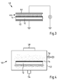
- the Fig. 3 shows such a system 40.
- the system 40 has a first grounded, planar electrode 42 and another, planar electrode 44, to which a high voltage U ⁇ 1 kV can be applied. Between the two electrodes 42, 44, the system 40 has a receiving region for arranging a substrate body 12, on which a corresponding hardcoat layer 14 is applied.
- the application of high voltage to the electrode 44 generates a lightning rain 46, which acts on the hardcoat layer 14 and together with the generated by the lightning storm 46 ozone causes the polar portion of the interfacial energy ⁇ S of the substrate body 12 facing away from surface 48 of the hard coat layer 14 is increased.
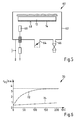
- the Fig. 4 shows a suitable low-pressure plasma system 50.
- the low-pressure plasma system 50 has a vacuum chamber 52 with a receiving area for placing a substrate body 12 for an optical element 10 with a hardcoat layer 14 applied thereto.
- the vacuum chamber 52 has a connection 54 for a vacuum pump.
- the vacuum chamber 52 has a gas inlet 56 through which oxygen, argon, a mixture of oxygen and nitrogen or oxygen and argon can be introduced into the vacuum chamber 52 in particular.
- the low-pressure plasma system 50 includes a microwave generator 58, by means of which the vacuum chamber 52 can be acted upon with microwaves to ignite at a pressure P in the vacuum chamber 52 of P ⁇ 10 Pa, a plasma with which the hardcoat layer 14 on the substrate body 12 treated becomes.
- the Fig. 5 shows such a plant 60.
- a vacuum chamber 62 with electrically conductive walls and a receiving area for arranging a substrate body 12 with a hardcoat layer 14th
- the vacuum chamber 62 has a port 64 for a vacuum pump and has a gas inlet 66.
- a glow electrode 68 to which a high voltage U ⁇ 1 kV can be applied to in a gas atmosphere consisting of oxygen, argon, air or mixtures thereof, whose pressure P in a pressure range between 0.1 Pa and 1 Pa is to ignite a plasma for treating the surface 48 of the hardcoat layer 14.
- the hardcoat layer 14 is also possible for the hardcoat layer 14 to be produced from a sol-gel hardcoat composition containing a fluorosurfactant as a leveling additive.
- the dispersive and polar components are measured here by the so-called OWRK method using the test liquids diiodomethane and ethylene glycol, which are described, for example, in US Pat Dissertation by Carsten Al, Friedrich-Alexander-University Er Weg-Nuremberg (2002), published on 08.07.2004 on p. 54 and p. 55 , is described.
- the table shows that the use of a flow control additive containing fluorosurfactant causes the polar fraction of the interfacial energy of the hardcoat layer applied to a substrate body to be smaller than that of a flow control additive that is silicone-based.
- the Fig. 6 illustrates with the graph 70, the diffusivity D F of the coating 15 on the substrate body 12 of an optical element 10.
- the hardcoat layer 14 of the substrate body 12 is here made of a sol-gel hardcoat composition containing as a leveling additive a fluorosurfactant.
- the Fig. 6 shows with the curve 72 the increase of the density c FS for the water molecules embedded in the substrate body 12 as a function of time t, when the optical element 10 is exposed from a dry environment in which the humidity is low, in a high humidity environment is arranged. After about 150 hours, the density c FS for the water molecules stored in the substrate body 12 is saturated here, ie the amount of water molecules stored in the substrate body is then approximately invariant with respect to time.
- the curve 74 shows the increase in the density c FS in the substrate body of a in the Fig. 1 however, it has a hard coat layer corresponding to the hard coat layer 14, the structure and thickness of the hard coat layer 14 in the optical element 10 corresponds, but made of a sol-gel hardcoat composition with a silicone-based leveling additive is.
- curve 64 is the substrate body in this optical element even after more than 200h not even slightly saturated.
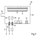
- the Fig. 7 shows a system 80 for the corresponding application of foreign structures on such a hard coat layer or on further layers of an optical element.
- the system 80 has a vacuum chamber 82 with electrically conductive walls, in which a substrate body 12 coated with a hard lacquer layer 14, for example a lens blank can be arranged.
- the vacuum chamber 82 has an opening 84 for connection to a valve assembly and vacuum pump, which allow to create in the vacuum chamber 82 a precisely defined composition for a gas atmosphere having a predetermined pressure.
- the glow electrodes 86, 88 are made of a nanoparticle material.
- the glow electrodes 86, 88 are connected via feedthroughs 90, 92 in the wall of the vacuum chamber 82 to a device for providing a high voltage.
- a glow discharge can be ignited in the vacuum chamber 82, in which the nanoparticle material of the glow electrodes is sputtered onto the hardcoat layer 14 at a pressure of, for example, 10 -4 mbar, so that they accumulate there.
- the system 80 is basically also suitable for applying partial layers for an antireflection coating to the hardcoat layer 14 with attached nanoparticles is suitable.
- an electron beam evaporator 93 is arranged in the system 80, with which then the different materials for layers in an antireflection coating can be vapor-deposited onto the substrate body 12.
- an ion source 94 is preferably also integrated into the system 80. This ion source is designed such that it permits ion bombardment of the substrate body 12 during vapor deposition of coatings with an ion energy E I which can be set favorably and preferably in a range 1eV ⁇ E I ⁇ 100 eV.
- the glow electrodes 86, 88 in the vacuum chamber 82 must be sufficiently close to the substrate body 12, so that the corresponding nanoparticles can be reflected uniformly on this and still scattered on this individually, so that they are not visible.
- nanoparticle coatings are known, for example. as disturbing effects of long-used glow lamps in vapor-deposited layers. Here, however, they want to produce much less dense than is the case with a long-used glow lamp. In addition, of course, the aim is that these nanoparticle deposits can be generated correspondingly quickly.
- an electrode material is chosen here which atomises relatively well at the residual gas pressure to be set and the glow discharge voltage.
- the electrode material is chosen here in such a way that it locally particularly effectively influences the layers deposited above it in the relevant optical element 10 with impurities.
- suitable materials for the nanoparticles, the gas type for the residual gas to be ionized, the pressure to be set and the voltage for the glow discharge depend on the desired structure of the layers, in particular the desired structure of the layer which is vapor-deposited directly onto the nanoparticles.
- a hardcoat layer 14 As an alternative to applying stubborn particles to a hardcoat layer 14, it is also possible to deposit foreign substances or foreign structures (for example molecules or nanoparticles) as impurities or impurities on the surface before staining a layer in a corresponding vacuum system and then to evaporate it later. This can e.g. also be done by previously in the material, e.g. The base material of the substrate body 12, such as in a spectacle lens, or in the hardcoat layer, if it is desired to modify the properties of the layer, introduces finely divided substances which, if they lie on the surface, locally influence the chemical bonding force of the applied layer in such a way that impurities are produced in the deposited layer at the points where the particles of the base material lie on the surface.
- foreign substances or foreign structures for example molecules or nanoparticles
- the diffusivity D F of a coating 15 of an optical element 10 can also be achieved by a targeted modification of the surface chemistry and energy.
- a modification of an interface in an optical element 10 may, for example, in addition also be produced with coatings that are prepared by wet chemical or physical processes.
- such interfaces can also be modified by means of printing, for example by means of nanoimprints or by bombardment with high-energy particles.
- nanoparticles on a layer applied to a substrate body 12 can in principle also be deposited with the electron beam evaporator 93 in the installation 80.
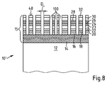
- the Fig. 8 shows a further optical element 10 'as a partial section, which has a substrate body 12 made of plastic, for example made of the plastic CR39.
- a substrate body 12 made of plastic, for example made of the plastic CR39.
- the structure of the optical element 10 of the Fig. 1 corresponds, this is in the Fig. 8 through in the Fig. 1 used numbers indicated as reference numerals.
- the optical element 10 Unlike the optical element 10 Fig. 1
- the optical element 10 'includes a plurality of holes 100.
- the holes 100 extend from the surface 48 of the coating 15 to the hardcoat layer 14. However, the hardcoat layer 14 is not penetrated by the holes 100.
- the holes 100 act as microscopic and / or mesoscopic pores in the coating 15 which increase their diffusivity D F.
- the diameter D L of the holes satisfies the following relationship: D L ⁇ 5 ⁇ m.
- the holes 100 in the coating 15 of the optical element 10 ' are produced, for example, by means of a focused electron beam or ion beam in a vacuum chamber.
- the Fig. 9 shows a system 110 for generating the above-mentioned microscopic or mesoscopic pores in the coating 15.
- the system 110 has a vacuum chamber 112, in which an electron and / or ion source 114 is disposed.
- the electron and / or ion source 114 is associated with an acceleration unit 116 and a deflection unit 118.
- the electron and / or ion source 114 is used for applying the coating 15 from an optical element 10 'arranged in the vacuum chamber 112 with a particle beam of electrons and / or ions.
- the electrons or ions are randomly distributed onto the surface of the optical element 10 'to be treated, so that the entire surface 48 is covered with diffusion-permeable holes.
- the deflection unit e.g. be arranged yet an electron or ion-optical diffractive structure.
- the accelerating unit 116 ensures that the electrons or ions have sufficient energy to perforate a coating 15 to be modified in their diffusion properties so that the otherwise diffusion-barrier layers become more permeable.
- the deflection unit 118 controls the particle beam provided by the electron and / or ion source 114 preferably via a random number generator. This makes it possible to achieve that the holes 100 produced by an optical element 10 'in the coating 110 in the coating 15 are approximately statistically distributed over the surface, so that the microscopic or mesoscopic structures of the holes do not produce any visible diffraction phenomena under visible light.
- Another way of simultaneously generating a plurality of holes by ion bombardment is to provide, in front of the actual ion source, a plate with a plurality of randomly distributed holes acting as a screen aperture. This screen aperture is then imaged on the surface of the relevant optical element. The optical element is thereby exposed to the corresponding particle beam until the holes produced in the coating or a layer of the coating are sufficiently deep to achieve the desired diffusion-influencing effect. By moving the plate or the optical element, it is possible to displace the locations where a particle beam is applied to the optical element.
- the electrons or ions must have a sufficiently high kinetic energy above the damage threshold of the surface to be processed.
- the choice of the type of ion on the effect can also have an influence.
- a regular pattern of "holes” or perturbations can also be generated.
- Such patterns could, for example, be the result of the fact that the focused electron or ion beam itself is an interference figure and therefore has a regularity: this has opposite to the above have the advantage that with a "burning process" a multiplicity of holes can be generated at once by placing the relevant individual interference patterns step by step in order to cover the entire optical element, ie for example the spectacle lens.
- the Fig. 10 shows another system 120 for generating the above-mentioned microscopic or mesoscopic pores in the coating 15 of an optical element 10 '.
- the system 120 includes a laser 122 for generating pulsed laser light, for which the pulse duration t P preferably applies: t P ⁇ 15 ns.
- the laser beam is directed by an optical system 124 to a highly reflective target 126, which is referred to as an amplitude or preferably as a pure phase object acts and generates a speckle pattern on the optical element 10 '.
- the system 120 includes a vacuum chamber 127 having an optical window 128 which acts as a lens. Through the window 128, the laser light of the laser 122 is directed onto the optical element 10 'arranged in the vacuum chamber 126. The wavelength of the laser light is selected so that it is absorbed in the coating 15 of the optical element 10 'and thereby generates corresponding holes 100 in the coating 15.
- an inventive optical element can be designed in particular as a lens, as a spectacle lens or as a spectacle lens blank or a spectacle lens semi-finished product.
- An optical element 10, 10 ' for example a spectacle lens or spectacle glass blank, has a substrate body 12 made of a plastic, which is preferably transparent in the visible spectral range, and a coating 15 comprising a plurality of layers 14, 16, 18 which has a hardcoat layer adjoining the substrate body 12 14 includes.
- the coating 15 has a diffusivity D F , which arranges the absorption of water molecules passing through the coating 15 in the substrate body 12 and the release of water molecules from the substrate body 12 through the coating 15 from a side of the coating 15 facing away from the substrate body 12
Landscapes
- Physics & Mathematics (AREA)
- Optics & Photonics (AREA)
- General Physics & Mathematics (AREA)
- Ophthalmology & Optometry (AREA)
- Health & Medical Sciences (AREA)
- Engineering & Computer Science (AREA)
- General Health & Medical Sciences (AREA)
- Mechanical Engineering (AREA)
- Manufacturing & Machinery (AREA)
- Chemical & Material Sciences (AREA)
- Inorganic Chemistry (AREA)
- Surface Treatment Of Optical Elements (AREA)
- Eyeglasses (AREA)
Priority Applications (2)
| Application Number | Priority Date | Filing Date | Title |
|---|---|---|---|
| PL14163993T PL2801846T3 (pl) | 2013-05-06 | 2014-04-09 | Element optyczny z powłoką o wysokiej dyfuzyjności |
| EP19179410.6A EP3561552A1 (fr) | 2013-05-06 | 2014-04-09 | Élement optique dote d'un revetement a haute diffusivite |
Applications Claiming Priority (1)
| Application Number | Priority Date | Filing Date | Title |
|---|---|---|---|
| DE102013208310.6A DE102013208310B4 (de) | 2013-05-06 | 2013-05-06 | Optisches Element mit Substratkörper und Hartlackschicht sowie Herstellungsverfahren hierfür |
Related Child Applications (2)
| Application Number | Title | Priority Date | Filing Date |
|---|---|---|---|
| EP19179410.6A Division EP3561552A1 (fr) | 2013-05-06 | 2014-04-09 | Élement optique dote d'un revetement a haute diffusivite |
| EP19179410.6A Division-Into EP3561552A1 (fr) | 2013-05-06 | 2014-04-09 | Élement optique dote d'un revetement a haute diffusivite |
Publications (2)
| Publication Number | Publication Date |
|---|---|
| EP2801846A1 true EP2801846A1 (fr) | 2014-11-12 |
| EP2801846B1 EP2801846B1 (fr) | 2019-07-24 |
Family
ID=50440577
Family Applications (2)
| Application Number | Title | Priority Date | Filing Date |
|---|---|---|---|
| EP19179410.6A Pending EP3561552A1 (fr) | 2013-05-06 | 2014-04-09 | Élement optique dote d'un revetement a haute diffusivite |
| EP14163993.0A Active EP2801846B1 (fr) | 2013-05-06 | 2014-04-09 | Élément optique doté d'un revêtement à haute diffusivité |
Family Applications Before (1)
| Application Number | Title | Priority Date | Filing Date |
|---|---|---|---|
| EP19179410.6A Pending EP3561552A1 (fr) | 2013-05-06 | 2014-04-09 | Élement optique dote d'un revetement a haute diffusivite |
Country Status (9)
| Country | Link |
|---|---|
| US (1) | US9778484B2 (fr) |
| EP (2) | EP3561552A1 (fr) |
| CN (1) | CN104142525B (fr) |
| DE (1) | DE102013208310B4 (fr) |
| DK (1) | DK2801846T3 (fr) |
| ES (1) | ES2746963T3 (fr) |
| HU (1) | HUE045721T2 (fr) |
| PL (1) | PL2801846T3 (fr) |
| PT (1) | PT2801846T (fr) |
Cited By (11)
| Publication number | Priority date | Publication date | Assignee | Title |
|---|---|---|---|---|
| WO2019166472A1 (fr) | 2018-02-27 | 2019-09-06 | Carl Zeiss Vision International Gmbh | Verre de lunettes pourvu d'au moins une couche nanostructurée et/ou microstructurée |
| EP3542956A1 (fr) | 2018-03-23 | 2019-09-25 | Carl Zeiss Vision International GmbH | Procédé de fabrication de lentilles de lunettes selon une ordonnance |
| EP3783420A1 (fr) * | 2019-08-21 | 2021-02-24 | Carl Zeiss Vision International GmbH | Verre de lunettes à effet filtrant pour lumière bleue et lunettes |
| EP3812142A1 (fr) | 2019-10-23 | 2021-04-28 | Carl Zeiss Vision International GmbH | Procédé de fabrication d'un verre de lunettes et produit comprenant un verre de lunettes |
| WO2021234030A1 (fr) | 2020-05-19 | 2021-11-25 | Carl Zeiss Vision Technical Service (Guangzhou) Ltd. | Article transparent, en particulier verre de lunettes, à propriétés antibactériennes et/ou antivirales et son procédé de fabrication |
| WO2021234032A1 (fr) | 2020-05-19 | 2021-11-25 | Carl Zeiss Vision Technical Service (Guangzhou) Ltd. | Verre de lunettes à propriétés antibuée |
| EP3928966A1 (fr) | 2020-06-26 | 2021-12-29 | Carl Zeiss Vision International GmbH | Procédé de fabrication d'une lentille revêtue |
| EP3944001A1 (fr) | 2020-07-24 | 2022-01-26 | Carl Zeiss Vision International GmbH | Verre de lunettes pourvu d'un scellement périphérique et son procédé de fabrication |
| WO2022018279A2 (fr) | 2020-07-24 | 2022-01-27 | Carl Zeiss Vision International Gmbh | Verre de lunettes à propriétés antibactériennes et/ou antivirales et son procédé de fabrication |
| WO2022101428A2 (fr) | 2020-11-13 | 2022-05-19 | Carl Zeiss Vision International Gmbh | Verre de lunettes à propriétés antibactériennes et/ou antivirales et son procédé de fabrication |
| WO2022193292A1 (fr) | 2021-03-19 | 2022-09-22 | Carl Zeiss Vision International Gmbh | Verre de lunettes à propriétés antibactériennes et/ou antivirales et son procédé de fabrication |
Families Citing this family (10)
| Publication number | Priority date | Publication date | Assignee | Title |
|---|---|---|---|---|
| CN103984120B (zh) * | 2014-05-30 | 2015-06-10 | 奥特路(漳州)光学科技有限公司 | 一种防蓝光光学镜片的制造方法 |
| EP3339940B1 (fr) | 2016-12-22 | 2020-11-04 | Carl Zeiss Vision International GmbH | Procédé de production d'un revêtement sur un verre de lunette et verre de lunette |
| US20180239102A1 (en) * | 2017-02-20 | 2018-08-23 | Corning Incorporated | Optical mount |
| JP6995491B2 (ja) | 2017-04-21 | 2022-01-14 | キヤノン株式会社 | 光学薄膜、光学素子、光学素子の製造方法 |
| DE102018105859A1 (de) * | 2018-03-14 | 2019-09-19 | Fraunhofer-Gesellschaft zur Förderung der angewandten Forschung e.V. | Reflexionsminderndes Schichtsystem und Verfahren zu dessen Herstellung |
| EP3543003A1 (fr) | 2018-03-23 | 2019-09-25 | Carl Zeiss Vision International GmbH | Palet de verre de lunettes ainsi que procédé et dispositif de fabrication d'un verre de lunettes à partir d'un palet de verre de lunettes |
| EP3561581A1 (fr) | 2018-04-24 | 2019-10-30 | Carl Zeiss Vision International GmbH | Verre de lunette à revêtement photochromique et son procédé de fabrication |
| EP3605155B1 (fr) * | 2018-08-02 | 2021-11-10 | Essilor International | Lentille ophtalmique comprenant un revêtement interférentiel multicouche et son procédé de fabrication |
| JP7418098B2 (ja) * | 2019-04-26 | 2024-01-19 | キヤノン株式会社 | 光学多層膜の成膜方法および光学素子の製造方法 |
| US20220316045A1 (en) * | 2021-03-31 | 2022-10-06 | Kla Corporation | System and method for ion-assisted deposition of optical coatings |
Citations (4)
| Publication number | Priority date | Publication date | Assignee | Title |
|---|---|---|---|---|
| EP0698798A2 (fr) | 1994-08-26 | 1996-02-28 | Leybold Aktiengesellschaft | Lentille optique en matière plastique recouverte |
| US20110058142A1 (en) * | 2006-11-23 | 2011-03-10 | Essilor International (Compagnie Generale d'Otique | Optical Article Comprising a Double-Layer Abrasion and Scratch Resistant Coating and Method for Production Thereof |
| US20110305827A1 (en) * | 2008-07-01 | 2011-12-15 | Essilor International (Compagnie Generale D'optique) | Methods of Using a Non-Photocatalytic Porous Coating as an Antisoiling Coating |
| EP2437084A1 (fr) | 2010-10-01 | 2012-04-04 | Carl Zeiss Vision GmbH | Lentille optique avec revêtement anti-rayure et anti-refléchissant |
Family Cites Families (12)
| Publication number | Priority date | Publication date | Assignee | Title |
|---|---|---|---|---|
| JPH0642002B2 (ja) * | 1983-07-29 | 1994-06-01 | セイコーエプソン株式会社 | プラスチックレンズ |
| CA2162451A1 (fr) * | 1994-12-22 | 1996-06-23 | John P. Murphy | Pellicule anti-reflet pour lunettes |
| FR2846753A1 (fr) * | 2002-11-06 | 2004-05-07 | Pentax Corp | Verre antireflechissant de lunettes et procede pour sa production |
| DE102006008784A1 (de) | 2006-02-24 | 2007-09-06 | Rodenstock Gmbh | Kratzfeste entspiegelte Oberfläche mit Antifog-Eigenschaften |
| JP4462273B2 (ja) * | 2007-01-23 | 2010-05-12 | セイコーエプソン株式会社 | 光学物品およびその製造方法 |
| FI121742B (fi) * | 2007-07-04 | 2011-03-31 | Theta Optics Ltd Oy | Menetelmä optisen tuotteen valmistamiseksi ja laitteisto |
| CN101790695B (zh) * | 2007-08-10 | 2011-12-21 | 大日本印刷株式会社 | 硬涂膜 |
| JP5313587B2 (ja) * | 2008-07-31 | 2013-10-09 | 学校法人慶應義塾 | 反射防止膜及びこれを有する光学部品、交換レンズ及び撮像装置 |
| EP2248865A1 (fr) * | 2009-05-07 | 2010-11-10 | Essilor International (Compagnie Générale D'Optique) | Compositions de gel/sol antistatiques et articles optiques revêtus avec celles-ci |
| WO2011044519A2 (fr) * | 2009-10-09 | 2011-04-14 | Yazaki Corporation | Revêtements antireflet durables |
| JP2012128135A (ja) * | 2010-12-15 | 2012-07-05 | Seiko Epson Corp | 光学物品およびその製造方法 |
| FR2973940A1 (fr) * | 2011-04-08 | 2012-10-12 | Saint Gobain | Element en couches pour l’encapsulation d’un element sensible |
-
2013
- 2013-05-06 DE DE102013208310.6A patent/DE102013208310B4/de active Active
-
2014
- 2014-04-09 PT PT14163993T patent/PT2801846T/pt unknown
- 2014-04-09 HU HUE14163993A patent/HUE045721T2/hu unknown
- 2014-04-09 PL PL14163993T patent/PL2801846T3/pl unknown
- 2014-04-09 ES ES14163993T patent/ES2746963T3/es active Active
- 2014-04-09 EP EP19179410.6A patent/EP3561552A1/fr active Pending
- 2014-04-09 EP EP14163993.0A patent/EP2801846B1/fr active Active
- 2014-04-09 DK DK14163993.0T patent/DK2801846T3/da active
- 2014-05-06 CN CN201410188130.2A patent/CN104142525B/zh active Active
- 2014-05-06 US US14/270,923 patent/US9778484B2/en active Active
Patent Citations (4)
| Publication number | Priority date | Publication date | Assignee | Title |
|---|---|---|---|---|
| EP0698798A2 (fr) | 1994-08-26 | 1996-02-28 | Leybold Aktiengesellschaft | Lentille optique en matière plastique recouverte |
| US20110058142A1 (en) * | 2006-11-23 | 2011-03-10 | Essilor International (Compagnie Generale d'Otique | Optical Article Comprising a Double-Layer Abrasion and Scratch Resistant Coating and Method for Production Thereof |
| US20110305827A1 (en) * | 2008-07-01 | 2011-12-15 | Essilor International (Compagnie Generale D'optique) | Methods of Using a Non-Photocatalytic Porous Coating as an Antisoiling Coating |
| EP2437084A1 (fr) | 2010-10-01 | 2012-04-04 | Carl Zeiss Vision GmbH | Lentille optique avec revêtement anti-rayure et anti-refléchissant |
Non-Patent Citations (3)
| Title |
|---|
| "Dissertation von Carsten Weiß, Friedrich-Alexander-Universität Erlangen-Nürnberg", 2002, pages: S.54,S.5 |
| U. SCHULZ ET AL.: "Near-infrared spectroscopy for monitoring water permeability of optical coatings on plastics", APPLIED OPTICS, vol. 862, 1997, pages 26 |
| VERÖFFENTLICHUNG KUI-XIANG MA ET AL.: "Investigation of surface energy for organic light emitting polymers and indium tin oxide", THIN SOLID FILMS, vol. 140, 2000, pages 371 |
Cited By (22)
| Publication number | Priority date | Publication date | Assignee | Title |
|---|---|---|---|---|
| WO2019166472A1 (fr) | 2018-02-27 | 2019-09-06 | Carl Zeiss Vision International Gmbh | Verre de lunettes pourvu d'au moins une couche nanostructurée et/ou microstructurée |
| EP3542956A1 (fr) | 2018-03-23 | 2019-09-25 | Carl Zeiss Vision International GmbH | Procédé de fabrication de lentilles de lunettes selon une ordonnance |
| WO2019179660A1 (fr) | 2018-03-23 | 2019-09-26 | Carl Zeiss Vision International Gmbh | Procédé de fabrication de verres à lunettes suivant une ordonnance |
| US11586053B2 (en) | 2019-08-21 | 2023-02-21 | Carl Zeiss Vision International Gmbh | Spectacle lens with filter effect for blue light and spectacles |
| EP3783420A1 (fr) * | 2019-08-21 | 2021-02-24 | Carl Zeiss Vision International GmbH | Verre de lunettes à effet filtrant pour lumière bleue et lunettes |
| WO2021032804A1 (fr) | 2019-08-21 | 2021-02-25 | Carl Zeiss Vision International Gmbh | Verre de lunettes à effet de filtre pour la lumière bleue et lunettes |
| EP3812142A1 (fr) | 2019-10-23 | 2021-04-28 | Carl Zeiss Vision International GmbH | Procédé de fabrication d'un verre de lunettes et produit comprenant un verre de lunettes |
| WO2021078989A1 (fr) | 2019-10-23 | 2021-04-29 | Carl Zeiss Vision International Gmbh | Procédé de production d'un verre de lunettes et produit comprenant un verre de lunettes |
| US11958305B2 (en) | 2019-10-23 | 2024-04-16 | Carl Zeiss Vision International Gmbh | Method of producing a spectacle lens and product comprising a spectacle lens |
| WO2021234030A1 (fr) | 2020-05-19 | 2021-11-25 | Carl Zeiss Vision Technical Service (Guangzhou) Ltd. | Article transparent, en particulier verre de lunettes, à propriétés antibactériennes et/ou antivirales et son procédé de fabrication |
| WO2021234032A1 (fr) | 2020-05-19 | 2021-11-25 | Carl Zeiss Vision Technical Service (Guangzhou) Ltd. | Verre de lunettes à propriétés antibuée |
| WO2021260196A1 (fr) | 2020-06-26 | 2021-12-30 | Carl Zeiss Vision International Gmbh | Procédé de fabrication d'une lentille revêtue |
| EP4197767A1 (fr) | 2020-06-26 | 2023-06-21 | Carl Zeiss Vision International GmbH | Procédé de fabrication d'une lentille revêtue |
| EP3928966A1 (fr) | 2020-06-26 | 2021-12-29 | Carl Zeiss Vision International GmbH | Procédé de fabrication d'une lentille revêtue |
| US12005659B2 (en) | 2020-06-26 | 2024-06-11 | Carl Zeiss Vision International Gmbh | Method for manufacturing a coated lens |
| WO2022018279A2 (fr) | 2020-07-24 | 2022-01-27 | Carl Zeiss Vision International Gmbh | Verre de lunettes à propriétés antibactériennes et/ou antivirales et son procédé de fabrication |
| EP3944001A1 (fr) | 2020-07-24 | 2022-01-26 | Carl Zeiss Vision International GmbH | Verre de lunettes pourvu d'un scellement périphérique et son procédé de fabrication |
| US11940596B2 (en) | 2020-07-24 | 2024-03-26 | Carl Zeiss Vision International Gmbh | Spectacle lens with antibacterial and/or antiviral properties and method for manufacturing the same |
| WO2022101428A2 (fr) | 2020-11-13 | 2022-05-19 | Carl Zeiss Vision International Gmbh | Verre de lunettes à propriétés antibactériennes et/ou antivirales et son procédé de fabrication |
| WO2022101428A3 (fr) * | 2020-11-13 | 2022-06-23 | Carl Zeiss Vision International Gmbh | Verre de lunettes à propriétés antibactériennes et/ou antivirales et son procédé de fabrication |
| WO2022193292A1 (fr) | 2021-03-19 | 2022-09-22 | Carl Zeiss Vision International Gmbh | Verre de lunettes à propriétés antibactériennes et/ou antivirales et son procédé de fabrication |
| WO2022195121A1 (fr) | 2021-03-19 | 2022-09-22 | Carl Zeiss Vision International Gmbh | Verre de lunettes à propriétés antibactériennes et/ou antivirales et son procédé de fabrication |
Also Published As
| Publication number | Publication date |
|---|---|
| ES2746963T3 (es) | 2020-03-09 |
| HUE045721T2 (hu) | 2020-01-28 |
| EP3561552A1 (fr) | 2019-10-30 |
| DE102013208310B4 (de) | 2019-07-04 |
| CN104142525A (zh) | 2014-11-12 |
| US20140327876A1 (en) | 2014-11-06 |
| EP2801846B1 (fr) | 2019-07-24 |
| US9778484B2 (en) | 2017-10-03 |
| CN104142525B (zh) | 2017-10-03 |
| PT2801846T (pt) | 2019-09-17 |
| DK2801846T3 (da) | 2019-10-21 |
| PL2801846T3 (pl) | 2020-01-31 |
| DE102013208310A1 (de) | 2014-11-06 |
Similar Documents
| Publication | Publication Date | Title |
|---|---|---|
| EP2801846B1 (fr) | Élément optique doté d'un revêtement à haute diffusivité | |
| EP3011370B1 (fr) | Procédé de fabrication d'une couche antireflet | |
| EP2274641B1 (fr) | Procédé pour la fabrication d'un système de couches d'interférence diminuant la réflexion | |
| EP0529268B1 (fr) | Couche dure antireflet pour lentille en plastique | |
| DE112016002132B4 (de) | Basis mit einem Film mit geringer Reflexion | |
| DE102007009512A1 (de) | Optisches Element mit einer Antibeschlagsschicht und Verfahren zu dessen Herstellung | |
| DE102015100091A1 (de) | Schichtsystem und optisches Element mit einem Schichtsystem | |
| EP3158370A1 (fr) | Élément optique muni d'un revêtement réfléchissant | |
| WO2009074146A2 (fr) | Procédé de réalisation d'une couche réduisant la réflexion et élément optique pourvu d'une couche réduisant la réflexion | |
| EP1307767B1 (fr) | Revetement reduisant la reflexion | |
| DE112018002226T5 (de) | Glassubstrat mit aufgebrachtem film, gegenstand und verfahren zur herstellung eines glassubstrats mit aufgebrachtem film | |
| WO2015110546A1 (fr) | Procédé de production d'un système de couches antireflets et système de couches antireflets | |
| DE102008014900A1 (de) | Schichtsystem zur Beheizung optischer Oberflächen und gleichzeitiger Reflexminderung | |
| DE102021112288B4 (de) | Schichtsystem mit Antibeschlag- und Antireflex-Eigenschaften und Verfahren zur Herstellung eines Schichtsystems | |
| EP1912913B1 (fr) | Systeme de couches photocatalytique presentant une course de commutation elevee et procede de production de ce systeme | |
| DE10201492B4 (de) | Optisches Schichtsystem | |
| DE102009030303A1 (de) | Verfahren zur Herstellung von Antireflexschicht-bildenden Beschichtungen sowie Antireflexbeschichtungen | |
| DE102004042650B4 (de) | Verfahren zum Abscheiden von photokatalytischen Titanoxid-Schichten | |
| DE102013103075B4 (de) | Verfahren zur Herstellung einer Entspiegelungsschicht auf einem Substrat | |
| DE102017003042B3 (de) | Gradienten-Hartschicht mit sich änderndem E-Modul | |
| DE102016123016A1 (de) | Verfahren zur Herstellung einer hydrophilen optischen Beschichtung, hydrophile optische Beschichtung und optisches Element mit der hydrophilen optischen Beschichtung | |
| DE102012100294B4 (de) | Verfahren zur Herstellung eines Kunststoffsubstrats mit einer Lackschicht und Kunststoffsubstrat mit einer Lackschicht | |
| DE102012206945A1 (de) | Entspiegelungsschichtsystem auf einem Substrat und Verfahren zu seiner Herstellung |
Legal Events
| Date | Code | Title | Description |
|---|---|---|---|
| PUAI | Public reference made under article 153(3) epc to a published international application that has entered the european phase |
Free format text: ORIGINAL CODE: 0009012 |
|
| 17P | Request for examination filed |
Effective date: 20140409 |
|
| AK | Designated contracting states |
Kind code of ref document: A1 Designated state(s): AL AT BE BG CH CY CZ DE DK EE ES FI FR GB GR HR HU IE IS IT LI LT LU LV MC MK MT NL NO PL PT RO RS SE SI SK SM TR |
|
| AX | Request for extension of the european patent |
Extension state: BA ME |
|
| R17P | Request for examination filed (corrected) |
Effective date: 20150512 |
|
| RBV | Designated contracting states (corrected) |
Designated state(s): AL AT BE BG CH CY CZ DE DK EE ES FI FR GB GR HR HU IE IS IT LI LT LU LV MC MK MT NL NO PL PT RO RS SE SI SK SM TR |
|
| RAP1 | Party data changed (applicant data changed or rights of an application transferred) |
Owner name: CARL ZEISS VISION INTERNATIONAL GMBH |
|
| STAA | Information on the status of an ep patent application or granted ep patent |
Free format text: STATUS: EXAMINATION IS IN PROGRESS |
|
| 17Q | First examination report despatched |
Effective date: 20181119 |
|
| REG | Reference to a national code |
Ref country code: DE Ref legal event code: R079 Ref document number: 502014012260 Country of ref document: DE Free format text: PREVIOUS MAIN CLASS: G02B0001100000 Ipc: G02B0001111000 |
|
| GRAP | Despatch of communication of intention to grant a patent |
Free format text: ORIGINAL CODE: EPIDOSNIGR1 |
|
| STAA | Information on the status of an ep patent application or granted ep patent |
Free format text: STATUS: GRANT OF PATENT IS INTENDED |
|
| RIC1 | Information provided on ipc code assigned before grant |
Ipc: G02B 1/12 20060101ALI20190123BHEP Ipc: G02C 7/02 20060101ALI20190123BHEP Ipc: G02B 1/111 20150101AFI20190123BHEP Ipc: G02B 1/113 20150101ALI20190123BHEP Ipc: G02B 1/14 20150101ALI20190123BHEP |
|
| INTG | Intention to grant announced |
Effective date: 20190225 |
|
| RIN1 | Information on inventor provided before grant (corrected) |
Inventor name: HAIDL, MARKUS Inventor name: HUGENBERG, NORBERT Inventor name: PENG, BIN Inventor name: KRAUSE, MICHAEL Inventor name: KOLLO, ANJA Inventor name: FAUL, SILVIA Inventor name: KRAUS, STEFAN Inventor name: PUETZ, DR., JOERG Inventor name: WINTER, KARL-HEINZ Inventor name: HANSSEN, ADALBERT Inventor name: VON BLANCKENHAGEN, BERNHARD Inventor name: STROISCH, MARC Inventor name: GREEN, ERWIN Inventor name: NEUFFER, ANDREAS Inventor name: GLOEGE, THOMAS Inventor name: MACIONCZYK, FRANK Inventor name: KRIEGER, MICHAEL Inventor name: HOLZ, LOTHAR Inventor name: KIEFER, PATRICK |
|
| GRAS | Grant fee paid |
Free format text: ORIGINAL CODE: EPIDOSNIGR3 |
|
| GRAA | (expected) grant |
Free format text: ORIGINAL CODE: 0009210 |
|
| STAA | Information on the status of an ep patent application or granted ep patent |
Free format text: STATUS: THE PATENT HAS BEEN GRANTED |
|
| AK | Designated contracting states |
Kind code of ref document: B1 Designated state(s): AL AT BE BG CH CY CZ DE DK EE ES FI FR GB GR HR HU IE IS IT LI LT LU LV MC MK MT NL NO PL PT RO RS SE SI SK SM TR |
|
| REG | Reference to a national code |
Ref country code: GB Ref legal event code: FG4D Free format text: NOT ENGLISH |
|
| REG | Reference to a national code |
Ref country code: CH Ref legal event code: EP |
|
| REG | Reference to a national code |
Ref country code: DE Ref legal event code: R096 Ref document number: 502014012260 Country of ref document: DE |
|
| REG | Reference to a national code |
Ref country code: AT Ref legal event code: REF Ref document number: 1158857 Country of ref document: AT Kind code of ref document: T Effective date: 20190815 |
|
| REG | Reference to a national code |
Ref country code: IE Ref legal event code: FG4D Free format text: LANGUAGE OF EP DOCUMENT: GERMAN |
|
| REG | Reference to a national code |
Ref country code: PT Ref legal event code: SC4A Ref document number: 2801846 Country of ref document: PT Date of ref document: 20190917 Kind code of ref document: T Free format text: AVAILABILITY OF NATIONAL TRANSLATION Effective date: 20190829 |
|
| REG | Reference to a national code |
Ref country code: DK Ref legal event code: T3 Effective date: 20191015 |
|
| REG | Reference to a national code |
Ref country code: NL Ref legal event code: FP |
|
| REG | Reference to a national code |
Ref country code: LT Ref legal event code: MG4D |
|
| REG | Reference to a national code |
Ref country code: HU Ref legal event code: AG4A Ref document number: E045721 Country of ref document: HU |
|
| PG25 | Lapsed in a contracting state [announced via postgrant information from national office to epo] |
Ref country code: FI Free format text: LAPSE BECAUSE OF FAILURE TO SUBMIT A TRANSLATION OF THE DESCRIPTION OR TO PAY THE FEE WITHIN THE PRESCRIBED TIME-LIMIT Effective date: 20190724 Ref country code: LT Free format text: LAPSE BECAUSE OF FAILURE TO SUBMIT A TRANSLATION OF THE DESCRIPTION OR TO PAY THE FEE WITHIN THE PRESCRIBED TIME-LIMIT Effective date: 20190724 Ref country code: SE Free format text: LAPSE BECAUSE OF FAILURE TO SUBMIT A TRANSLATION OF THE DESCRIPTION OR TO PAY THE FEE WITHIN THE PRESCRIBED TIME-LIMIT Effective date: 20190724 Ref country code: HR Free format text: LAPSE BECAUSE OF FAILURE TO SUBMIT A TRANSLATION OF THE DESCRIPTION OR TO PAY THE FEE WITHIN THE PRESCRIBED TIME-LIMIT Effective date: 20190724 Ref country code: BG Free format text: LAPSE BECAUSE OF FAILURE TO SUBMIT A TRANSLATION OF THE DESCRIPTION OR TO PAY THE FEE WITHIN THE PRESCRIBED TIME-LIMIT Effective date: 20191024 Ref country code: NO Free format text: LAPSE BECAUSE OF FAILURE TO SUBMIT A TRANSLATION OF THE DESCRIPTION OR TO PAY THE FEE WITHIN THE PRESCRIBED TIME-LIMIT Effective date: 20191024 |
|
| PG25 | Lapsed in a contracting state [announced via postgrant information from national office to epo] |
Ref country code: IS Free format text: LAPSE BECAUSE OF FAILURE TO SUBMIT A TRANSLATION OF THE DESCRIPTION OR TO PAY THE FEE WITHIN THE PRESCRIBED TIME-LIMIT Effective date: 20191124 Ref country code: LV Free format text: LAPSE BECAUSE OF FAILURE TO SUBMIT A TRANSLATION OF THE DESCRIPTION OR TO PAY THE FEE WITHIN THE PRESCRIBED TIME-LIMIT Effective date: 20190724 Ref country code: AL Free format text: LAPSE BECAUSE OF FAILURE TO SUBMIT A TRANSLATION OF THE DESCRIPTION OR TO PAY THE FEE WITHIN THE PRESCRIBED TIME-LIMIT Effective date: 20190724 Ref country code: GR Free format text: LAPSE BECAUSE OF FAILURE TO SUBMIT A TRANSLATION OF THE DESCRIPTION OR TO PAY THE FEE WITHIN THE PRESCRIBED TIME-LIMIT Effective date: 20191025 Ref country code: RS Free format text: LAPSE BECAUSE OF FAILURE TO SUBMIT A TRANSLATION OF THE DESCRIPTION OR TO PAY THE FEE WITHIN THE PRESCRIBED TIME-LIMIT Effective date: 20190724 |
|
| REG | Reference to a national code |
Ref country code: ES Ref legal event code: FG2A Ref document number: 2746963 Country of ref document: ES Kind code of ref document: T3 Effective date: 20200309 |
|
| PG25 | Lapsed in a contracting state [announced via postgrant information from national office to epo] |
Ref country code: EE Free format text: LAPSE BECAUSE OF FAILURE TO SUBMIT A TRANSLATION OF THE DESCRIPTION OR TO PAY THE FEE WITHIN THE PRESCRIBED TIME-LIMIT Effective date: 20190724 Ref country code: RO Free format text: LAPSE BECAUSE OF FAILURE TO SUBMIT A TRANSLATION OF THE DESCRIPTION OR TO PAY THE FEE WITHIN THE PRESCRIBED TIME-LIMIT Effective date: 20190724 |
|
| PG25 | Lapsed in a contracting state [announced via postgrant information from national office to epo] |
Ref country code: SM Free format text: LAPSE BECAUSE OF FAILURE TO SUBMIT A TRANSLATION OF THE DESCRIPTION OR TO PAY THE FEE WITHIN THE PRESCRIBED TIME-LIMIT Effective date: 20190724 Ref country code: IS Free format text: LAPSE BECAUSE OF FAILURE TO SUBMIT A TRANSLATION OF THE DESCRIPTION OR TO PAY THE FEE WITHIN THE PRESCRIBED TIME-LIMIT Effective date: 20200224 Ref country code: SK Free format text: LAPSE BECAUSE OF FAILURE TO SUBMIT A TRANSLATION OF THE DESCRIPTION OR TO PAY THE FEE WITHIN THE PRESCRIBED TIME-LIMIT Effective date: 20190724 |
|
| REG | Reference to a national code |
Ref country code: DE Ref legal event code: R097 Ref document number: 502014012260 Country of ref document: DE |
|
| PLBE | No opposition filed within time limit |
Free format text: ORIGINAL CODE: 0009261 |
|
| STAA | Information on the status of an ep patent application or granted ep patent |
Free format text: STATUS: NO OPPOSITION FILED WITHIN TIME LIMIT |
|
| PG2D | Information on lapse in contracting state deleted |
Ref country code: IS |
|
| 26N | No opposition filed |
Effective date: 20200603 |
|
| PG25 | Lapsed in a contracting state [announced via postgrant information from national office to epo] |
Ref country code: SI Free format text: LAPSE BECAUSE OF FAILURE TO SUBMIT A TRANSLATION OF THE DESCRIPTION OR TO PAY THE FEE WITHIN THE PRESCRIBED TIME-LIMIT Effective date: 20190724 |
|
| PG25 | Lapsed in a contracting state [announced via postgrant information from national office to epo] |
Ref country code: MC Free format text: LAPSE BECAUSE OF FAILURE TO SUBMIT A TRANSLATION OF THE DESCRIPTION OR TO PAY THE FEE WITHIN THE PRESCRIBED TIME-LIMIT Effective date: 20190724 |
|
| PG25 | Lapsed in a contracting state [announced via postgrant information from national office to epo] |
Ref country code: LU Free format text: LAPSE BECAUSE OF NON-PAYMENT OF DUE FEES Effective date: 20200409 |
|
| PG25 | Lapsed in a contracting state [announced via postgrant information from national office to epo] |
Ref country code: IE Free format text: LAPSE BECAUSE OF NON-PAYMENT OF DUE FEES Effective date: 20200409 |
|
| PG25 | Lapsed in a contracting state [announced via postgrant information from national office to epo] |
Ref country code: MT Free format text: LAPSE BECAUSE OF FAILURE TO SUBMIT A TRANSLATION OF THE DESCRIPTION OR TO PAY THE FEE WITHIN THE PRESCRIBED TIME-LIMIT Effective date: 20190724 Ref country code: CY Free format text: LAPSE BECAUSE OF FAILURE TO SUBMIT A TRANSLATION OF THE DESCRIPTION OR TO PAY THE FEE WITHIN THE PRESCRIBED TIME-LIMIT Effective date: 20190724 |
|
| PG25 | Lapsed in a contracting state [announced via postgrant information from national office to epo] |
Ref country code: MK Free format text: LAPSE BECAUSE OF FAILURE TO SUBMIT A TRANSLATION OF THE DESCRIPTION OR TO PAY THE FEE WITHIN THE PRESCRIBED TIME-LIMIT Effective date: 20190724 |
|
| PGFP | Annual fee paid to national office [announced via postgrant information from national office to epo] |
Ref country code: NL Payment date: 20240418 Year of fee payment: 11 |
|
| PGFP | Annual fee paid to national office [announced via postgrant information from national office to epo] |
Ref country code: PL Payment date: 20240329 Year of fee payment: 11 |
|
| PGFP | Annual fee paid to national office [announced via postgrant information from national office to epo] |
Ref country code: GB Payment date: 20240419 Year of fee payment: 11 |
|
| PGFP | Annual fee paid to national office [announced via postgrant information from national office to epo] |
Ref country code: DE Payment date: 20240418 Year of fee payment: 11 |
|
| PGFP | Annual fee paid to national office [announced via postgrant information from national office to epo] |
Ref country code: DK Payment date: 20240423 Year of fee payment: 11 |
|
| PGFP | Annual fee paid to national office [announced via postgrant information from national office to epo] |
Ref country code: CH Payment date: 20240501 Year of fee payment: 11 |
|
| PGFP | Annual fee paid to national office [announced via postgrant information from national office to epo] |
Ref country code: ES Payment date: 20240524 Year of fee payment: 11 |
|
| PGFP | Annual fee paid to national office [announced via postgrant information from national office to epo] |
Ref country code: AT Payment date: 20240419 Year of fee payment: 11 Ref country code: CZ Payment date: 20240402 Year of fee payment: 11 |
|
| PGFP | Annual fee paid to national office [announced via postgrant information from national office to epo] |
Ref country code: IT Payment date: 20240424 Year of fee payment: 11 Ref country code: FR Payment date: 20240425 Year of fee payment: 11 |
|
| PGFP | Annual fee paid to national office [announced via postgrant information from national office to epo] |
Ref country code: PT Payment date: 20240328 Year of fee payment: 11 |
|
| PGFP | Annual fee paid to national office [announced via postgrant information from national office to epo] |
Ref country code: TR Payment date: 20240401 Year of fee payment: 11 Ref country code: HU Payment date: 20240422 Year of fee payment: 11 Ref country code: BE Payment date: 20240418 Year of fee payment: 11 |