EP2801679B1 - Bodenbelagssystem und verfahren zur verbindung - Google Patents
Bodenbelagssystem und verfahren zur verbindung Download PDFInfo
- Publication number
- EP2801679B1 EP2801679B1 EP12860227.3A EP12860227A EP2801679B1 EP 2801679 B1 EP2801679 B1 EP 2801679B1 EP 12860227 A EP12860227 A EP 12860227A EP 2801679 B1 EP2801679 B1 EP 2801679B1
- Authority
- EP
- European Patent Office
- Prior art keywords
- face
- tongue
- connector
- panel
- flooring system
- Prior art date
- Legal status (The legal status is an assumption and is not a legal conclusion. Google has not performed a legal analysis and makes no representation as to the accuracy of the status listed.)
- Active
Links
Images


Classifications
-
- E—FIXED CONSTRUCTIONS
- E04—BUILDING
- E04F—FINISHING WORK ON BUILDINGS, e.g. STAIRS, FLOORS
- E04F15/00—Flooring
- E04F15/02—Flooring or floor layers composed of a number of similar elements
- E04F15/02038—Flooring or floor layers composed of a number of similar elements characterised by tongue and groove connections between neighbouring flooring elements
-
- E—FIXED CONSTRUCTIONS
- E04—BUILDING
- E04F—FINISHING WORK ON BUILDINGS, e.g. STAIRS, FLOORS
- E04F15/00—Flooring
- E04F15/02—Flooring or floor layers composed of a number of similar elements
- E04F15/02005—Construction of joints, e.g. dividing strips
-
- E—FIXED CONSTRUCTIONS
- E04—BUILDING
- E04F—FINISHING WORK ON BUILDINGS, e.g. STAIRS, FLOORS
- E04F15/00—Flooring
- E04F15/02—Flooring or floor layers composed of a number of similar elements
- E04F15/02044—Separate elements for fastening to an underlayer
-
- E—FIXED CONSTRUCTIONS
- E04—BUILDING
- E04F—FINISHING WORK ON BUILDINGS, e.g. STAIRS, FLOORS
- E04F15/00—Flooring
- E04F15/02—Flooring or floor layers composed of a number of similar elements
- E04F15/02044—Separate elements for fastening to an underlayer
- E04F2015/0205—Separate elements for fastening to an underlayer with load-supporting elongated furring elements between the flooring elements and the underlayer
-
- E—FIXED CONSTRUCTIONS
- E04—BUILDING
- E04F—FINISHING WORK ON BUILDINGS, e.g. STAIRS, FLOORS
- E04F2201/00—Joining sheets or plates or panels
- E04F2201/01—Joining sheets, plates or panels with edges in abutting relationship
- E04F2201/0107—Joining sheets, plates or panels with edges in abutting relationship by moving the sheets, plates or panels substantially in their own plane, perpendicular to the abutting edges
- E04F2201/0115—Joining sheets, plates or panels with edges in abutting relationship by moving the sheets, plates or panels substantially in their own plane, perpendicular to the abutting edges with snap action of the edge connectors
-
- E—FIXED CONSTRUCTIONS
- E04—BUILDING
- E04F—FINISHING WORK ON BUILDINGS, e.g. STAIRS, FLOORS
- E04F2201/00—Joining sheets or plates or panels
- E04F2201/04—Other details of tongues or grooves
- E04F2201/041—Tongues or grooves with slits or cuts for expansion or flexibility
-
- E—FIXED CONSTRUCTIONS
- E04—BUILDING
- E04F—FINISHING WORK ON BUILDINGS, e.g. STAIRS, FLOORS
- E04F2201/00—Joining sheets or plates or panels
- E04F2201/05—Separate connectors or inserts, e.g. pegs, pins, keys or strips
- E04F2201/0517—U- or C-shaped brackets and clamps
Definitions
- the present invention relates to a connector for interlocking floor panels, and more particularly, to the floor panels having tongues on the sides thereof, and to the connector having grooves in the sides, the tongues are engaged with the grooves to connect the floor panels.
- interlocking floor panels are used for a long period of time and which are easily connected to each other.
- the technique is developed further so that the interlocking panels can be used to decorate the wall by connecting the panels to each other and secured on the wall.
- the floor panels each have tongue and groove formed on the cooperated sides thereof so that the floor panels can be connected to each other by engaging the tongues with the grooves.
- the second is to use a connector which is located between the panels so as to connect the floor panels.
- CN 97190692.0 and U.S. Pat. No. 6,874,292 to Unilin Beheer BV disclose the floor panels that have a connection portion composed of a tongue and a groove in the opposite sides thereof, and a mechanical locking device is connected to the connection portion so that the floor panels do not disengaged upwardly from reach other in the direction that is perpendicular to the relative sides, and in the direction that is parallel to the underside of the panels.
- There are two tools are required when manufacturing the panels and the equipment for manufacturing the panels is required to have higher standard.
- the assemblers When assembling the panels, the assemblers have to choose the installation direction and this is an inconvenient requirement for the assemblers.
- the obvious disadvantage is that, in order to have the tongues and the grooves, a certain width of the material of the board has to be discarded. If the material that is discarded for making the tongues and the grooves reaches 10% of the whole width of the board, this means that 10% of the floor area composed of the panels is disappeared. This also means that the manufacturing cost increases 10%. It is also a waste for the natural source.
- the second catalogue uses a connector to connect the panels, the connector is made to have symmetrical structure, and the panels have the same structure on the sides to be cooperated with the connector. That is to say, the panels have grooves on the sides, and the connector has tongues on the sides, so that the tongues are engaged with the grooves.
- China Patent Application No. 200910304656.1 discloses a connector with a tongue on each of two sides thereof, and the tongue has an engaging piece on the top and the bottom thereof.
- the panels has a groove in each of the sides thereof and each of the grooves has a notch which is shaped to be engaged with the engaging piece.
- the connection is by using the connector meets the requirement for connecting the panels.
- the existed equipment cannot make the groove and the notch in one action, wherein the notch is perpendicular to the groove.
- the locking force in the horizontal direction is made by the flexibility of the material of the connector. If the flexibility of the material of the connector is not strong enough, the locking force in the horizontal direction is not sufficient. If the material for the connector has larger flexibility, when assembling the panels, the assembler has to hammer the other side of the panel to force the connection portions of the panels and the connector to be deformed, so that the connector is connected between the panels. This causes difficulties when assembling and disassembling. Furthermore, the hammering action may damage the groove of the hammered sides of the panels.
- U.S. Pat. No. 6,460,306 , U.S. Pat. No. 7,614,791 and China Utility Model ZL 02249916.4 306 disclose a similar connector for connecting floor panels, and the connector has two tongues in opposite directions.
- a base board is connected to the underside of the connector and is connected to the connector by an upright board.
- the base board has a flange on each of two sides thereof.
- the panels has a groove in two opposite sides thereof and a positioning slot is defined in the underside of each of the two sides of the panel.
- the tongues are engaged with the grooves of the panels, and the flanges are engaged with the positioning slots so as to connect the panels.
- connection between the tongues and the grooves provides the locking feature in the vertical direction
- connection between the flanges and the positioning slots provides the locking feature in the horizontal direction, so that the connection between the panels is secure and reliable.
- the panel in order to engage flanges with the positioning slots, the panel has to be tilt so that the side to be connected is positioned to be over the flange so as to be connected with the connector. This is inconvenient for the assemblers because when the long sides of the panels are connected to each other, and the short sides are then to be connected.
- the connected long sides cannot be tilt so that the short side cannot be connected to each other.
- the short side can only use a horizontal groove to be connected with each other, and the horizontal groove cannot provide a secure locking feature.
- U.S. Pat. No. 6,769,217 discloses an interconnecting disengageable flooring system wherein the base board on the underside of the connector does not have the positioning ridge, so that the panels can be horizontally connected to each other. Nevertheless, an engaging slot is required in the base board or the underside of the connector, and the panel has an engaging member in the groove or on the underside thereof. Furthermore, the assembling action has to hammer from the other side of the panels to force the connection portion between the connector and the panel to be deformed slightly, such that the panels can be successfully connected to each other. Again, the similar disadvantages mentioned above are existed.
- CN201924551 disclose a connector for connecting floor panels, and the connector has two tongues in opposite directions as well.
- a central shaft is arranged at the middle part of a lock catch batten; a spring bolt is arranged at the top of the central shaft, and a left mortise and a right mortise are respectively arranged at two sides of the central shaft; and a floorboard is provided with a groove corresponding to the spring bolt and tenons corresponding to the left and right mortises; a filler strip is arranged above the lock catch batten.
- CN 201 924 551U discloses a flooring system, which are deemed as the closest prior art when compared with the subject matter disclosed in the current application.
- the present invention intends to provide a connector for interlocking floor panels and the floor panels, eliminate the shortcomings mentioned above.
- the present invention relates to a flooring system as defined in claim 1 and comprises multiple panels connected to each other and connectors.
- Each panel has a first surface, a second surface which is located corresponding to the first surface and at least three sides. At least two sides of the panel each have a tongue.
- the panels each have a groove defined in one side thereof, and each groove has an inner side.
- a top protrusion extends outward from the side having the groove and is located above the groove.
- Each top protrusion has an end face and a bottom face.
- the second surface of each panel has a slot defined in the side having the tongue. Each slot has an inside which faces the side having the slot.
- a tongue is formed between the groove and the slot.
- Each tongue has a lower protrusion.
- Each tongue has a tongue top face which faces the groove.
- Each tongue has a tongue outer face which faces the side having the groove.
- the tongue outer face does not protrude beyond the end face of the top protrusion.
- An outer inclined face is formed on an outside of the lower protrusion and connected to the tongue outer face.
- An inner inclined face is formed on an inside of the lower protrusion and faces the slot.
- At least one first stepped portion of the panels is formed between the tongue top face and the inner side.
- Each of the at least one first stepped portion has an engaging face on a top thereof.
- Each of the at least one first stepped portion has a contact face facing the side having the groove.
- Each connector is an elongate connector and has a symmetric top end
- the connector has abase board on a lower end thereof, an upright portion extends from the base board the base board has a bottom face and two side faces
- the base board has a locking member on a top of each of the two sides thereof, a locking piece extends laterally from each of two sides of the upright portion, the locking piece has a side face
- the upright portion has a top face
- an engaging slot is defined between the locking piece of the upright portion and the locking member of the base board, the engaging slot defines atop wall in a bottom of the locking piece
- the upright portion has an inside wall formed in each of two sides thereof
- the base board has a lower recess defined in a top face of each of two sides thereof
- the locking member is located between the lower recess and the side face
- the locking member has a wedge-shaped cross section
- the lower recess has an inclined wall formed at the inside of the locking member
- a first ridge extends between the top wall
- the first stepped portion and a second stepped portion are formed between the tongue top face and the inner side.
- the first stepped portion has the engaging face on the top thereof and the contact face on the side thereof.
- the second stepped portion has an engaging face on a top thereof and a contact face on the side thereof.
- the first stepped portion extends from an area between the tongue top face and the inner side of the groove.
- the first stepped portion has the engaging face on the top thereof.
- the tongue has a lower protrusion.
- a top recess is formed between the tongue outer face and the inner inclined face of the lower protrusion.
- a top inclined face is connected between an outside of the top recess and the tongue outer face.
- An outer inclined face is connected between an inside of the top recess and the inner inclined face.
- the outer inclined face of the lower protrusion is a curved face.
- the outer inclined face of the lower portion is an inclined face.
- the inner inclined face of the lower protrusion is a curved face.
- the inner inclined face of the lower protrusion is an inclined face.
- the tongue has a resilient slot defined in an underside thereof.
- the first ridge and the second ridge are formed between the top wall and the inside wall.
- the first ridge has the engaging face formed at the underside thereof and the contact face formed at the side thereof.
- the second ridge has an engaging face formed at an underside thereof and a contact face formed at a side thereof.
- a top bump is formed between the inside wall and the inclined wall of the lower recess.
- a side inclined face is connected between the outside of the top bump and the inclined wall.
- a top inclined face is connected between the top of the top bump and the inside wall.
- a notch is defined between the side inclined face and the top inclined face.
- the upright portion has multiple grooves defined in the top face thereof.
- the top face of the connector has a main groove and a groove is defined in an inner end of the main groove.
- the top face of the connector has a central groove which allows the locking piece to be resiliently deformed.
- the bottom face of the base board has multiple grooves extending along a longitudinal direction of the connector.
- the outside of the locking member has an inclined guide face which is located between a top most point of the locking member and the side face.
- the distance between the two side faces of the two locking pieces of the upright portion of the connector is smaller than that between the side faces of the bottom face of the base board.
- a space is defined between the base board of the connector and the upright portion.
- Another space is defined between the upright portion and the locking piece.
- an inclined face is formed between the side face of the locking piece of the connector and the top wall.
- Another inclined face is formed between the engaging face of the first ridge of the connector and the contact face.
- two sides of the side face of the base board of the connector are recessed sides.
- an inclined face is formed between the first surface of the panel and the end face.
- a curved face is formed between end face of the top protrusion of the panel and the bottom face.
- an inclined face is formed between the engaging face of the first stepped portion of the panel and the contact face.
- Another inclined face is formed between the tongue top face of the tongue of the panel and the tongue outer face.
- a buffering layer is attached to the engaging slot of the connector and the buffering layer is made by a material that is softer than that of the connector.
- the buffering layer is attached on the inclined wall, the side inclined face, the top inclined face, the inside wall, the engaging face and the top wall.
- the buffering layer is attached on the side face of the locking piece.
- the top face of the locking piece of the connector has a buffering plate extending from the center thereof.
- the present invention also relates to a method for connecting the panels by using the connectors system having the following steps:
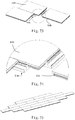
- the panels of the present invention does not need to be lift up so that the same tongue can be installed to the long side and the short side of the panel, and the same groove can be defined in the long side and the short side of the panel.
- the manufacturers need only one blade/tool to make the groove in the long side and the short side of the panel.
- the connector is extruded as long as the shape of the connector is formed correspondent to the groove of the panel.
- the connector can be made by engineering plastic, polymer material, wood and metal alloy.
- the connector is extruded and cut into pieces as desired.
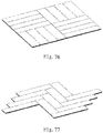
- the panels of the present invention can be assembled to show different patterns and arrangements. The engagement of the tongues and the grooves are made by pressing the panels so that no hammering action is needed to one side of the panels, so that the panels are not damaged by hammering.
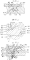
- the first embodiment of the connector 20 for connecting the panels 10 of the present invention is an elongate connector 20 which is an inverted T-shaped connected when viewed from either end thereof.
- the left portion and the right portion of the connector 20 are symmetric to each other.
- the connector 20 comprises a base board 21 on the lower end thereof, and an upright portion 22 extends from the base board 21.
- the base board 21 has a bottom face 210 and two side faces 211.
- the base board 21 of the connector 20 has a locking member 23 on the top of each of the two sides thereof.
- a locking piece 24 extends laterally from each of two sides of the upright portion 22.
- the locking pieces 24 each have a side face 240.
- the upright portion 22 has a top face 220, in this embodiment, there are two grooves 221 defined in the top face 220, and another groove 222 is located between the two grooves 221, wherein the two grooves 221 is deeper than the groove 222.
- An engaging slot 40 is defined between the locking piece 24 of the upright portion 22 and the locking member 23 of the base board 21.
- the engaging slot 40 defines a top wall 41 in the bottom of the locking piece 24.
- the upright portion 22 has an inside wall 42 formed in each of two sides thereof.
- the base board 21 has a lower recess 400 defined in the top face of each of two sides thereof.
- the locking member 23 is located between the lower recess 400 and the side face 211.
- the locking member 23 has a wedge-shaped cross section.
- the lower recess 400 has an inclined wall 410 formed at the inside thereof and facing the locking member 23.
- Three grooves 212 are defined along the longitudinal direction in the bottom face 210 of the base board 21.
- Fig. 3 shows the panel 10 of the present invention and comprises a first surface and a second surface which is located corresponding to the first surface. At least two of the three sides of the panel 10 each have a tongue 30. Only one side of the two panels 10 are shown for convenience of description of the connection between the connector 20 and the panels 10.
- the panel 10 has a groove 33 defined in the side having the tongue 30, the groove 33 has an inner side 330.
- a top protrusion 70 extends outward from the side having the groove 33.
- the top protrusion 70 has an end face 701 and a bottom face 702.
- the second surface of each panel 10 has a slot 72 defined in one side thereof.
- the slot 72 has an inside 721 which faces the side having the slot 72.
- a tongue 30 is formed between the groove 33 and the slot 72.
- the tongue 30 has a lower protrusion 300.
- the tongue 30 has a tongue top face 31 which faces the groove 33, and the tongue 30 has a tongue outer face 32 which faces the side having the groove 33.
- the tongue outer face 32 does not protrude beyond the end face 701 of the top protrusion 70 so that the surface of the panel 10 does not affected and the material for the panel 10 does not waste.
- a first stepped portion 34 is formed between the tongue top face 31 and the inner side 330.
- the first stepped portion 34 has an engaging face 341 on the top thereof.
- the first stepped portion 34 has a contact face 342 which faces the side of the panel 10.
- the tongue 30 is engaged with the engaging slot 40 of the connector 20.
- the tongue 30 has a lower protrusion 300 for being received in the engaging slot 40 of the connector 20.
- the lower protrusion 300 of the tongue 30 is engaged with the lower recess 400 of the connector 20.
- an outer inclined face 301 is formed between the outside of the lower protrusion 300 and the tongue outer face 32.
- An inner inclined face 302 is formed on the inside of the lower protrusion 300 and faces the slot 72.
- the outer inclined face 301 and the inner inclined face 302 are both a curved face.
- Fig. 1 shows that the distance between the side faces 240 of the two locking pieces 24 of the upright portion 22 of the connector 20 is smaller than that between the side faces 211 of the base board 21.
- An inclined guide face 420 is formed on the outside of the locking member 23 and located between the highest point of the locking member 23 and the side face 211 of the base board 21.
- FIG. 3 shows that the panel 10 on the left is connected to the connector 20, and the panel 10 on the right having the tongue 30 is moved toward the connector 20 with the engaging slot 40 on the same plane with the panel 10.
- the at least one side of the contact position is an inclined face or a curved face, so that the inclined face guides the panel 10 to change its height relative to the side of the connector 20.
- Fig. 3 shows that the panel 10 having the tongue 30 on the right is guided by the inclined face and lifted up.
- the horizontal distance L1 between a vertical extension line of the lowest point of the lower protrusion 300 of the tongue 30 of the panel 10 and a vertical extension line of the highest point of the tongue outer face 32 of the lower protrusion 300 is smaller than the horizontal distance L2 between a vertical extension line of the highest point of the locking member 23 of the connector 20 and a vertical extension line of the lowest point of the side face 240. As shown in Fig. 4 , L1 ⁇ L2.
- the lower protrusion 300 of the tongue 30 is moved into the lower recess 400 of the engaging slot 40 of the connector 20.
- the inner inclined face 302 of the lower protrusion 300 of the tongue 30 contacts the inclined wall 410 of the lower recess 400 of the connector 20.
- the contact face 342 of the first stepped portion 34 of the tongue 30 contacts the side face 240 of the connector 20 as shown in Fig. 5 , so that the panel 10 with the tongue 30 cannot be moved toward the connector 20 having the engaging slot 40 on the same plane.
- Fig. 5 is used to describe the steps for moving the panels 10 toward the connector 20.
- the panel 10 on the right is moved downward a little bit due to the gravity to allow the inner inclined face 302 of the lower protrusion 300 of the tongue 30 to contact the inclined wall 410 of the lower recess 400 of the connector 20.
- the contact face 342 of the first stepped portion 34 of the tongue 30 of the panel 10 contacts the side face 240 of the connector 20
- the panel 10 contacts the connector 20 by the inclined face which makes the movement of the panel 10 be easy without using any tool to force the panel 10 to move.
- the horizontal distance L3 between a vertical extension line of the lowest point of the lower protrusion 300 of the tongue 30 of the panel 10 and a vertical extension line of the contact face 342 of the first stepped portion 34 of the tongue 30 is larger than the horizontal distance L4 between a vertical extension line of the lowest point of the inclined wall 410 of the engaging slot 40 and a vertical extension line of the lowest point of the side face 240.
- the horizontal distance L5 between a vertical extension line of the outside of the contact face 342 of the first stepped portion 34 and the vertical line of the inner side 330 of the panel 10 is smaller than the horizontal distance L6 between a vertical extension line of an outside of the side face 240 and the vertical line of the highest point of the inside wall 42 of the engaging slot 42. As shown in Fig. 6 , L5 ⁇ L6.
- the contact face 32 of the first stepped portion 34 contacts the side face of the connector, so that the panel 10 and the connector 20 cannot be moved toward on the same plane.
- the inner inclined face 302 of the lower protrusion 300 of the tongue 30 pushes the inclined wall 410 of the engaging slot 40 to deform the material below the engaging slot 40 such that the tongue 30 is able to move downward and into the engaging slot 40.
- the locking member 23 is locked in the slot 72, and the inner inclined face 302 of the lower protrusion 300 of the tongue 30 contacts the inclined wall 410 of the engaging slot 40, the tongue 30 is engaged with the engaging slot 40 because that the material below the engaging slot 40 is deformed.
- the material below the engaging slot 40 returns to its initial status, the distance between the outside of the contact face 342 of the first stepped portion 34 and any point of the contact area between the inclined wall 410 and the inner inclined face 302 is larger than the distance between the intersection point between the side face 240 of the top wall 41 and the side face 240 to the correspondent contact portion of the inclined wall 410.
- the tongue 30 of the first embodiment cannot be engaged with the engaging slot 40 if the material below the engaging slot 40 is not deformed, so that the panel 10 is securely connected with the connector 20.
- the tongue 30 of the panel 10 is engaged with the engaging slot 40 of the connector 20 by pressing the panel 10.
- the assembler does not need to apply a huge force from the other side of the panel 10 so that the other side of the panel 10 is not damaged.
- the first embodiment of the present invention uses the pressing force to deform the material below the engaging slot 40 to let the inner inclined face 302 of the tongue 30 and the inclined wall 410 of the engaging slot 40 to guide the tongue 30 to be engaged with the engaging slot 40.
- the assembler can either press the panel by hands or feet along the direction shown in Figs. 6 and 7 to complete the engagement.
- the connector 20A for connecting the panels 10A of the present invention is an elongate connector 20A comprises a base board 21A on the lower end thereof, and an upright portion 22A extends from the base board 21A.
- the base board 21A has a bottom face 210A and two side faces 211A.
- the base board 21A of the connector 20A has a locking member 23A on the top of each of the two sides thereof.
- a locking piece 24A extends laterally from each of two sides of the upright portion 22A.
- the locking pieces 24A each have a side face 240A.
- the upright portion 22A has a top face 220A. In this embodiment, there are two grooves 221A defined in the top face 220A.
- An engaging slot 40A is defined between the locking piece 24A of the upright portion 22A and the locking member 23A of the base board 21A.
- the engaging slot 40A defines a top wall 41A in the bottom of the locking piece 24A.
- the upright portion 22A has an inside wall 42A formed in each of two sides thereof.
- the base board 21A has a lower recess 400A defined in the top face of each of two sides thereof.
- the locking member 23A is located between the lower recess 400A and the side face 211A.
- the locking member 23A has a wedge-shaped cross section.
- the lower recess 400A has an inclined wall 410A formed at the inside thereof and facing the locking member 23A.
- a first ridge 43A extends between the top wall 41A and the inside wall 42A, the first ridge 43A has an engaging face 431A at the underside thereof, and a contact face 432A is formed on a side of the first ridge 43A.
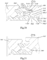
- Fig. 10 shows the second embodiment of the panel 10A of the present invention and comprises a first surface and a second surface which is located corresponding to the first surface. At least two of the three sides each have a tongue 30A.
- the panel 10A has a groove 33A defined in the side having the tongue 30A, the groove 33A has an inner side 330A.
- a top protrusion 70A extends outward from the side having the groove 33A.
- the top protrusion 70A has an end face 701A and a bottom face 702A.
- the second surface of the panel 10 has a slot 72A defined in one side thereof.
- the slot 72A has an inside 721A which faces the side having the slot 72A.
- a tongue 30A is formed between the groove 33A and the slot 72A.
- the tongue 30A has a tongue top face 31A which faces the groove 33A, and the tongue 30A has a tongue outer face 32A which faces the side of the panel 10A having the groove 33A.
- the tongue outer face 32A does not protrude beyond the end face 701A of the top protrusion 70A.
- the tongue 30A is engaged with the engaging slot 40A when the panel 10A is connected with the connector 20A.
- the tongue 30A has a lower protrusion 300A which is engaged with the lower recess 400A of the connector 20A.
- An outer inclined face 301A is formed on the outside of the lower protrusion 300A and the outer inclined face 301A connects the tongue outer face 32A,
- An inner inclined face 302A is formed on the inside of the lower protrusion 300A and faces the slot 72A.
- the outer inclined face 301A and the inner inclined face 302A are both a curved face.
- Fig. 9 shows that the distance between the side faces 240A of the two locking pieces 24A of the upright portion 22A of the connector 20A is smaller than that between the side faces 211A of the base board 21A.
- An inclined guide face 420A is formed on the outside of the locking member 23A and located between the highest point of the locking member 23A and the side face 211A.
- FIG. 9 shows that the panel 10A on the left is connected to the connector 20A, and the panel 10A on the right having the tongue 30A is moved toward the connector 20A with the engaging slot 40A on the same plane with the panel 10A.
- the at least one side of the contact position is an inclined face or a curved face, so that the inclined face guides the panel 10A to change its height relative to the side of the connector 20A.
- Fig. 9 shows that the panel 10A having the tongue 30A is guided by the inclined face and lifted up.
- the horizontal distance L1A between a vertical extension line of the lowest point of the lower protrusion 300A of the tongue 30A of the panel 10A and a vertical extension line of the highest point of the tongue outer face 32A of the lower protrusion 300A is smaller than the horizontal distance L2A between a vertical extension line of the highest point of the locking member 23A of the connector 20A and a vertical extension line of the lowest point of the contact face 432A of the first ridge 43A.
- the lower protrusion 300A of the tongue 30A is moved into the lower recess 400A of the engaging slot 40A of the connector 20A.
- the inner inclined face 302A of the lower protrusion 300A of the tongue 30A contacts the inclined wall 410A of the lower recess 400A of the connector 20A.
- the contact face 432A of the first ridge 43A of the panel 10A contacts the tongue outer face 32A of the tongue 30A as shown in Fig. 11 , so that the panel 10A with the tongue 30A cannot be moved toward the connector 20A having the engaging slot 40A on the same plane.
- Fig. 11 is used to describe the steps for moving the panels 10A toward the connector 20A.
- the panel 10A on the right is moved downward a little bit due to the gravity to allow the inner inclined face 302A of the lower protrusion 300A of the tongue 30A to contact the inclined wall 410A of the lower recess 400A of the connector 20A.
- the contact face 432A of the first ridge 43A of the panel 10A contacts the tongue outer face 32A of the tongue 30A
- the panel 10A contacts the connector 20A by the inclined face which makes the movement of the panel 10A be easy without using any tool to force the panel 10A to move.
- the horizontal distance L1A between a vertical extension line of the lowest point of the lower protrusion 300A of the tongue 30A of the panel 10A and a vertical extension line of the highest point of the tongue outer face 32A of the tongue 30A is larger than the horizontal distance L4 between a vertical extension line of the lowest point of the inclined wall 410A of the engaging slot 40A and a vertical extension line of the lowest point of the contact face 432 of the first ridge 43A.
- the horizontal distance L7A between a vertical extension line of the inner side 330A of the panel 10A and the vertical line of highest point of the tongue outer face 32A is larger than the horizontal distance L8A between a vertical extension line of an outside of the side face 240 of the connector 20A and the vertical line of the lowest point of the contact wall 432A of the first ridge 43A. As shown in Fig. 12 , L7A>L8A.
- the contact face 32A of the tongue 30A contacts the contact face 432A of the first ridge 43A, so that the panel 10A and the connector 20A cannot be moved toward on the same plane.
- the inner inclined face 302A of the lower protrusion 300Aof the tongue 30A pushes the inclined wall 410A of the engaging slot 40A to deform the material below the engaging slot 40A such that the tongue 30A is able to move downward and into the engaging slot 40A.
- the material below the engaging slot 40A bounces back by the natural flexibility thereof, the tongue top face 31A of the tongue 30A contacts the underside of the engaging face 431A of the first ridge 43A.
- the tongue 30A is then engaged with the engaging slot 40A so that the panel 10A does not disengaged from the connector 20A as shown in Fig. 14 .
- the locking member 23A is locked in the slot 72A, and the tongue top face 31A of the tongue 30A contacts the engaging face 431A of the first ridge 43A.
- the inner inclined face 302A of the lower protrusion 300A of the tongue 30A contacts the inclined wall 410A of the engaging slot 40A.
- the tongue 30A is engaged with the engaging slot 40A because that the material below the engaging slot 40A is deformed.
- the material below the engaging slot 40A After the tongue 30A is engaged with the engaging slot 40A, the material below the engaging slot 40A returns to its initial status, the distance between the outside of the tongue top face 31A of the tongue 30A and any point of the contact area between the inclined wall 410A and the inner inclined face 302A is larger than the distance between the intersection point between the engaging face 431A of the first ridge 43A of the engaging slot 40A and the contact face 432A to the correspondent contact portion of the inclined wall 410A.
- the tongue 30A of the second embodiment cannot be engaged with the engaging slot 40A if the material below the engaging slot 40A is not deformed, so that the tongue 30A is securely connected with the engaging slot 40A.
- the tongue 30A of the panel 10A is engaged with the engaging slot 40A of the connector 20A by pressing the panel 10A.
- the assembler does not need to apply a huge force to connect the panel 10A with the connector 20A, so that no huge force is applied to the other side of the panel 10A so that the other side of the panel 10A is not damaged.
- the second embodiment of the present invention uses the pressing force to deform the material below the engaging slot 40A to let the inner inclined face 302A of the tongue 30A and the inclined wall 410A of the engaging slot 40A to guide the tongue 30A to be engaged with the engaging slot 40A.
- the assembler can either press the panel 10A by hands or feet along the direction shown in Figs. 11 and 12 to complete the engagement.
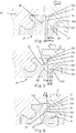
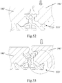
- Fig. 15 shows another embodiment based on the second embodiment of the present invention, wherein the tongue 30A' of the panel 10A' has a resilient slot 305A' defined in the underside thereof.
- the tongue 30A' of the panel 10A' is moved to the engaging slot 40A of the connector 20A, and when pressing the panel 10A' to be connected with the connector 20A, the resilient slot 305A' provide a space for deformation of the tongue 30A' of the panel 10A'.
- Fig. 17 shows the underside of the panel 10A' disclosed in Figs. 15 and 16 .
- the tongue 30A' is disclosed.
- the panel 10B is similar to the panel 10 in the first embodiment, and the connector 20B is similar to the connector 20A in the second embodiment.
- the panel 10B of the present invention comprises a first surface and a second surface which is located corresponding to the first surface. At least two of the three sides of the panel 10B each have a tongue 30B.
- the panel 10B has a groove 33B defined in the side having the tongue 30B, the groove 33B has an inner side 330B.
- a top protrusion 70B extends outward from the side having the groove 33B.
- the top protrusion 70B has an end face 701B and a bottom face 702B.
- the second surface of the panel 10B has a slot 72B defined in one side thereof.
- the slot 72B has an inside 721B which faces the side having the slot 72B.
- a tongue 30B is formed between the groove 33B and the slot 72B.
- the tongue 30B has a tongue top face 31B which faces the groove 33B, and the tongue 30B has a tongue outer face 32B which faces the side having the groove 33B.
- the tongue outer face 32B does not protrude beyond the end face 701B of the top protrusion 70B.
- a first stepped portion 34B is formed between the tongue top face 31B and the inner side 330B.
- the first stepped portion 34B has an engaging face 341B on the top thereof.
- the first stepped portion 34B has a contact face 342B which faces the side of the panel 10B.
- the tongue 30 has a lower protrusion 300B.
- An outer inclined face 301B is formed between the outside of the lower protrusion 300B and the tongue outer face 32B.
- An inner inclined face 302B is formed on the inside of the lower protrusion 300B and faces the slot 72B.
- Each of the outer inclined face 301B and the inner inclined face 302B of the lower protrusion 300B of the panel 10B is a curved face.
- Fig. 19 shows that the connector 20B for connecting the panels 10B of the third embodiment of the present invention comprises a base board 21B and an upright portion 22B extends from the base board 21B.
- the base board 21B has a bottom face 210B and two side faces 211B.
- the base board 21B of the connector 20B has a locking member 23B on the top of each of the two sides thereof.
- a locking piece 24B extends laterally from each of two sides of the upright portion 22B.
- the locking pieces 24B each have a side face 240B.
- the upright portion 22B has a top face 220B. In this embodiment, there are two grooves 221B defined in the top face 220B.
- a groove 222B is defined between the two grooves 221B wherein the two grooves 221B are deeper than the groove 222B.
- An engaging slot 40B is defined between the locking piece 24B of the upright portion 22B and the locking member 23B of the base board 21B.
- the engaging slot 40B defines a top wall 41B in the bottom of the locking piece 24B.
- the upright portion 22B has an inside wall 42B formed in each of two sides thereof.
- the base board 21B has a lower recess 400B defined in the top face of each of two sides thereof.
- the locking member 23B is located between the lower recess 400B and the side face 211B.
- the locking member 23B has a wedge-shaped cross section.
- the lower recess 400B has an inclined wall 410B formed at the inside thereof and facing the locking member 23B.
- a first ridge 43B extends between the top wall 41B and the inside wall 42B, the first ridge 43B has an engaging face 431B at the underside thereof, and a contact face 432B is formed on a side of the first ridge 43B.
- Fig. 19 shows that the distance between the side faces 240B of the two locking pieces 24B of the upright portion 22B of the connector 20B is smaller than that between the side faces 211B of the base board 21B.
- An inclined guide face 420B is formed on the outside of the locking member 23B and located between the highest point of the locking member 23B and the upright portion 22B.
- Two grooves 212B are defined in the bottom face 210B of the base board 21B and located along the longitudinal direction of the panel 20B.
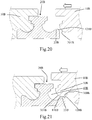
- FIG. 20 shows that the panel 10B on the left is connected to the connector 20B, and the panel 10B on the right having the tongue 30B on the right is moved toward the connector 20B with the engaging slot 40B on the same plane with the panel 10B.
- the at least one side of the contact position is an inclined face or a curved face, so that the inclined face guides the panel 10B to change its height relative to the side of the connector 20B.
- Fig. 20 shows that the panel 10B having the tongue 30B is guided by the inclined face and lifted up.
- the horizontal distance L1B between a vertical extension line of the lowest point of the lower protrusion 300B of the tongue 30B of the panel 10B and a vertical extension line of the highest point of the tongue outer face 32B of the lower protrusion 300B is smaller than the horizontal distance L2B between a vertical extension line of the highest point of the locking member 23B of the connector 20B and a vertical extension line of the lowest point of the contact face 432B of the first ridge 43B. As shown in Fig. 22 , L1B ⁇ L2B.
- the lower protrusion 300B of the tongue 30B is moved into the lower recess 400B of the engaging slot 40B of the connector 20B.
- the inner inclined face 302B of the lower protrusion 300B of the tongue 30B contacts the inclined wall 410B of the lower recess 400B of the connector 20B.
- the contact face 432B of the first ridge 43B of the panel 10B contacts the tongue outer face 32B of the tongue 30B as shown in Fig. 22 , so that the panel 10B with the tongue 30B cannot be moved toward the connector 20B having the engaging slot 40B on the same plane.
- Fig. 22 is used to describe the steps for moving the panels 10B toward the connector 20B.
- the panel 10B on the right is moved downward a little bit due to the gravity to allow the inner inclined face 302B of the lower protrusion 300B of the tongue 30B to contact the inclined wall 410B of the lower recess 400B of the connector 20B.
- the contact face 432B of the first ridge 43B of the panel 10B contacts the tongue outer face 32B of the tongue 30B, and before the contact face 342B of the first ridge 34B contacts the side face 240B of the locking piece 24B
- the panel 10B contacts the connector 20B by the inclined face which makes the movement of the panel 10B be easy without using any tool to force the panel 10B to move.
- the horizontal distance L1B between a vertical extension line of the lowest point of the lower protrusion 300B of the tongue 30B of the panel 10B and a vertical extension line of the highest point of the tongue outer face 32B of the tongue 30B is larger than the horizontal distance L4B between a vertical extension line of the lowest point of the inclined wall 410B of the engaging slot 40B and a vertical extension line of the lowest point of the contact face 432B of the first ridge 43B.
- the horizontal distance L5B between a vertical extension line of the inner side 330B of the panel 10B and the vertical line of the outside of the contact face 342B of the first stepped portion 34B is smaller than the horizontal distance L6B between a vertical extension line of the outside of the side face 240B of the engaging slot 40B of the connector 20B and the vertical line of the highest point of the inside wall 42B of the engaging slot 40B.
- L5B ⁇ L6B As shown in Fig. 23 , L5B ⁇ L6B.
- the horizontal distance L7B between a vertical extension line of the inner side 330B of the panel 10B and the vertical line of highest point of the tongue outer face 32B is larger than the horizontal distance L8B between a vertical extension line of an outside of the side face 240B of the connector 20B and the vertical line of the lowest point of the contact wall 432B of the first ridge 43B. As shown in Fig. 23 , L7B>L8B.
- the contact face 32B of the tongue 30B contacts the contact face 432B of the first ridge 43B, and the contact face 342B of the first stepped portion 34B contacts the side face 240B, so that the panel 10B and the connector 20B cannot be moved toward on the same plane.
- the inner inclined face 302B of the lower protrusion 300B of the tongue 30B pushes the inclined wall 410B of the engaging slot 40B to deform the material below the engaging slot 40B such that the tongue 30B is able to move downward and into the engaging slot 40B.
- the locking member 23B is locked in the slot 72B.
- the material below the engaging slot 40B bounces back by the natural flexibility thereof, the tongue top face 31B of the tongue 30B contacts the underside of the engaging face 431B of the first ridge 43B.
- the engaging face 341B of the first stepped portion 34B of the tongue 30B contacts the underside of the top wall 41B of the locking piece 24B of the engaging face 341B of the first stepped portion 34B.
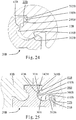
- the tongue 30B is then engaged with the engaging slot 40B so that the panel 10B does not disengaged from the connector 20B as shown in Fig. 25 .
- the tongue top face 31B of the tongue 30B contacts the engaging face 431B of the first ridge 43B.
- the engaging face 341B of the first stepped portion 34B of the tongue 30B contacts the top wall 41B of the locking piece 24B of the engaging face 341B of the first stepped portion 34B.
- the locking member 23B is engaged with the slot 72B.
- the inner inclined face 302B of the lower protrusion 300B of the tongue 30B contacts the inclined wall 410B of the engaging slot 40B.
- the tongue 30B is engaged with the engaging slot 40B because that the material below the engaging slot 40B is deformed.
- the material below the engaging slot 40B After the tongue 30B is engaged with the engaging slot 40B, the material below the engaging slot 40B returns to its initial status, the distance between the outside of the tongue top face 31B of the tongue 30B and any point of the contact area between the inclined wall 410B and the inner inclined face 302B is larger than the distance between the intersection point between the engaging face 431B of the first ridge 43B of the engaging slot 40B and the contact face 432B to the correspondent contact portion of the inclined wall 410B.
- the tongue 30B of the second embodiment cannot be engaged with the engaging slot 40B if the material below the engaging slot 40B is not deformed, so that the tongue 30B is securely connected with the engaging slot 40B.
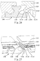
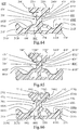
- Fig. 26 shows another embodiment based on the third embodiment of the present invention, wherein the connector 20B is similar to that of the third embedment, and the panel 10B' has an inclined face connected between the outer inclined face 301B' of the lower protrusion 300B' of the tongue 30B' and the inner inclined face 302B' of the tongue outer face 32B'.
- Fig. 27 shows that when the panel 10B' is moved toward the connector 20B the outer inclined face 301B' contacts the connector 20B, and the panel 10B' is lifted along the guide face 420B of the locking member 23B of the connector 20B.
- Figs. 28 to 30 shows the actions to connect the panel 10B with the connector 20B, wherein the panel 10B is connected to the connector 20B by way of pressing.
- the fourth embodiment is a further embedment based on the third embodiment.
- the connector 20C for connecting the panels 10C of the fourth embodiment of the present invention comprises a base board 21C and an upright portion 22C extends from the base board 21C.
- the base board 21C has a bottom face 210C and two side faces 211C.
- the base board 21C of the connector 20C has a locking member 23C on the top of each of the two sides thereof.
- a locking piece 24C extends laterally from each of two sides of the upright portion 22C.
- the locking pieces 24C each have a side face 240C.
- the upright portion 22C has a top face 220C. In this embodiment, there are two grooves 221C defined in the top face 220C.
- a groove 222C is defined between the two grooves 221C wherein the two grooves 221C are deeper than the groove 222C.
- An engaging slot 40C is defined between the locking piece 24C of the upright portion 22C and the locking member 23C of the base board 21C.
- the engaging slot 40C defines a top wall 41C in the bottom of the locking piece 24C.
- the upright portion 22C has an inside wall 42C formed in each of two sides thereof.
- the base board 21C has a lower recess 400C defined in the top face of each of two sides thereof.
- the locking member 23C is located between the lower recess 400C and the side face 211C.
- the locking member 23C has a wedge-shaped cross section.
- the lower recess 400C has an inclined wall 410C formed at the inside thereof and facing the locking member 23C.
- a first ridge 43B and a second ridge 44C extend between the top wall 41C and the inside wall 42D, the first ridge 43C has an engaging face 431C at the underside thereof, and a contact face 432C is formed on a side of the first ridge 43C.
- the second ridge 44C has an engaging face 441C at the underside thereof, and a contact face 442C is formed on a side of the second ridge 44C.
- Two grooves 212C are defined in the bottom face 210C of the base board 21C and located along the longitudinal direction of the panel 20C.
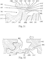
- Fig. 31 shows that the distance between the side faces 240C of the two locking pieces 24C of the upright portion 22C of the connector 20C is smaller than that between the side faces 211C of the base board 21C.
- An inclined guide face 420C is formed on the outside of the locking member 23C and located between the highest point of the locking member 23C and the side face 211C.
- the panel 10C of the present invention comprises a groove 33C defined in the side having the tongue 30C, the groove 33C has an inner side 330C.
- a top protrusion 70C extends outward from the side having the groove 33C.
- the top protrusion 70C has an end face 701C and a bottom face 702C.
- the second surface of the panel 10C has a slot 72C defined in one side thereof.
- the slot 72C has an inside 721C which faces the side having the slot 72C.
- a tongue 30C is formed between the groove 33C and the slot 72C.
- the tongue 30C has a tongue top face 31C which faces the groove 33C, and the tongue 30C has a tongue outer face 32C which faces the side having the groove 33C.
- the tongue outer face 32C does not protrude beyond the end face 701C of the top protrusion 70C.
- a first stepped portion 34C and a second stepped portion 35C are formed between the tongue top face 31C and the inner side 330C.
- the first stepped portion 34C has an engaging face 341C on the top thereof.
- the first stepped portion 34C has a contact face 342C which faces the side of the panel 10C.
- the second stepped portion 35C has an engaging face 351C on the top thereof.
- the second stepped portion 35C has a contact face 352C which faces the side of the panel 10C.
- the tongue 30C is engaged with the engaging slot 40C when the panel 10C is connected to the connector 20C.
- the tongue 30C has a lower protrusion 300C.
- An outer inclined face 301C is formed between the outside of the lower protrusion 300C and the tongue outer face 32C.
- An inner inclined face 302C is formed on the inside of the lower protrusion 300C and
- Each of the outer inclined face 301C and the inner inclined face 302C of the lower protrusion 300C of the panel 10B of the fourth embodiment is a curved face.
- FIG. 32 shows that the panel 10C on the left is connected to the connector 20C, and the panel 10C on the right having the tongue 30C is moved toward the connector 20C with the engaging slot 40C on the same plane with the panel 10C.
- the at least one side of the contact position is an inclined face or a curved face, so that the inclined face guides the panel 10C to change its height relative to the side of the connector 20C.
- Fig. 32 shows that the panel 10C having the tongue 30C of the fourth embodiment is guided by the inclined face and lifted up.
- the horizontal distance L1C between a vertical extension line of the lowest point of the lower protrusion 300C of the tongue 30C of the panel 10C and a vertical extension line of the highest point of the tongue outer face 32C of the lower protrusion 300C is smaller than the horizontal distance L2C between a vertical extension line of the highest point of the locking member 23C of the connector 20C and a vertical extension line of the lowest point of the contact face 442C of the second ridge 44C.
- the lower protrusion 300C of the tongue 30C is moved into the lower recess 400C of the engaging slot 40C of the connector 20C.
- the inner inclined face 302C of the lower protrusion 300C of the tongue 30C contacts the inclined wall 410C of the lower recess 400C of the connector 20C.
- the contact face 432C of the first ridge 43C of the panel 10C contacts the tongue outer face 32C of the tongue 30C.
- the contact face 442C of the second ridge 44C contacts the contact face 342 of the first stepped portion 34C, and the contact face 352C of the second stepped portion 35 contacts the side face 240 as shown in Fig.
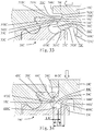
- Figs. 34 and 35 are used to describe the steps for moving the panels 10C toward the connector 20C.
- the panel 10C on the right is moved downward a little bit due to the gravity to allow the inner inclined face 302C of the lower protrusion 300C of the tongue 30C to contact the inclined wall 410C of the lower recess 400C of the connector 20C.
- the panel 10C contacts the connector 20C by the inclined face which makes the movement of the panel 10C be easy without using any tool to force the panel 10C to move.
- the horizontal distance L1C between a vertical extension line of the lowest point of the lower protrusion 300C of the tongue 30C of the panel 10C and a vertical extension line of the highest point of the tongue outer face 32C of the tongue 30C is larger than the horizontal distance L4C between a vertical extension line of the lowest point of the inclined wall 410C of the engaging slot 40C and a vertical extension line of the lowest point of the contact face 442 of the second ridge 44C.
- the horizontal distance L5C between a vertical extension line of the inner side 330C of the panel 10C and the vertical line of the outside of the contact face 342C of the first stepped portion 34C is smaller than the horizontal distance L6C between a vertical extension line of the outside of the side face 240C of the engaging slot 40C of the connector 20C and the vertical line of the highest point of the inside wall 42C of the engaging slot 40C.
- L5C ⁇ L6C As shown in Fig. 35 , L5C ⁇ L6C.
- the horizontal distance L7C between a vertical extension line of the inner side 330C of the panel 10C and the vertical line of highest point of the tongue outer face 32C is larger than the horizontal distance L8C between a vertical extension line of an outside of the side face 240C of the connector 20C and the vertical line of the lowest point of the contact wall 432C of the first ridge 43C. As shown in Fig. 35 , L7C>L8C.
- the contact face 32C of the tongue 30C contacts the contact face 432C of the first ridge 43C
- the contact face 342C of the first stepped portion 34C contacts the contact face 442C of the second ridge 44C
- the contact face 352C of the second stepped portion 35C contacts the side face 240c, so that the panel 10C and the connector 20C cannot be moved toward on the same plane.
- the inner inclined face 302C of the lower protrusion 300C of the tongue 30C pushes the inclined wall 410C of the engaging slot 40C to deform the material below the engaging slot 40C such that the tongue 30C is able to move downward and into the engaging slot 40C.
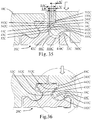
- Fig. 36 when the panel 10C with the tongue 30C is pressed downward, the material below the engaging slot 40C is deformed which is shown by the dotted line and the solid line in Fig. 37 .
- the tongue outer 32C of the tongue 30C is offset from contact face 432C of the first ridge 43C of the engaging slot 40C
- the contact face 342C of the first stepped portion 34C is offset from the contact face 442C of the second ridge 44C
- the contact face 352C of the second stepped portion 35C is offset from the side face 240C
- the lower protrusion 300C of the tongue 30C is engaged with the lower recess 400C of the engaging slot 40C by the guidance of the inner inclined face 302C of the lower protrusion 300C and the inclined wall 410C of the engaging slot 40C.
- the locking member 23C is locked in the slot 72C.
- the tongue top face 31C of the tongue 30C contacts the underside of the engaging face 431C of the first ridge 43C.
- the engaging face 341C of the first stepped portion 34C of the tongue 30C contacts the underside of the engaging face 441 of the second ridge 44C, and the engaging face 351C of the second stepped portion 35C contacts the underside of the top wall 41C of the engaging slot 40C.
- the tongue 30C is then engaged with the engaging slot 40C so that the panel 10C does not disengaged from the connector 20C as shown in Fig. 38 .
- Figs. 39 to 40 show the alternative embodiment of the connector based on the fourth embodiment, the top face of the connector is different from that of the fourth embodiment.
- the top face 220C' of the connector 20C' has a main groove 223C' and a groove 224C' is defined in the inner end of the main groove 223C'.
- the top face 220C" of the connector 20C" has a central groove 225C" which allows the locking piece 24C" to be resiliently deformed.
- the top face 220C" of the connector 20C" in Fig. 41 is a flat surface.
- Fig. 42 shows that the connector 20D for connecting the panels 10D of the third embodiment of the present invention comprises a base board 21D and an upright portion 22D extends from the base board 21D.
- the base board 21D has a bottom face 210D and two side faces 211D.
- the base board 21D of the connector 20D has a locking member 23D on the top of each of the two sides thereof.
- a locking piece 24D extends laterally from each of two sides of the upright portion 22D.
- the locking pieces 24D each have a side face 240D.
- the upright portion 22D has a top face 220D. In this embodiment, there are three grooves 221D defined in the top face 220D.
- An engaging slot 40D is defined between the locking piece 24D of the upright portion 22D and the locking member 23D of the base board 21D.
- the engaging slot 40D defines a top wall 41D in the bottom of the locking piece 24D.
- the upright portion 22D has an inside wall 42D formed in each of two sides thereof.
- the base board 21D has a lower recess 400D defined in the top face of each of two sides thereof.
- the locking member 23D is located between the lower recess 400D and the side face 211D.
- the locking member 23D has a wedge-shaped cross section.
- the lower recess 400D has an inclined wall 410D formed at the inside thereof and facing the locking member 23D.
- a first ridge 43D extends between the top wall 41D and the inside wall 42D, the first ridge 43D has an engaging face 431D at the underside thereof, and a contact face 432D is formed on a side of the first ridge 43D.
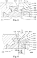
- a top bump 60D is formed between the inside wall 42D and the inclined wall 410D of the lower recess 400D.
- a side inclined face 601D is connected between the outside of the top bump 60D and the inclined wall 410D of the lower recess 400D.
- a top inclined face 602D is defined between the top of the top bump 60D and the inside wall 42D.
- Fig. 42 shows that the distance between the side faces 240D of the two locking pieces 24D of the upright portion 22D of the connector 20D is smaller than that between the side faces 211D of the base board 21D.
- An inclined guide face 420D is formed on the outside of the locking member 23D and located between the highest point of the locking member 23D and the side face 211D.
- Three grooves 212D are defined in the bottom face 210D of the base board 21D and located along the longitudinal direction of the panel 20D.
- the panel 10D of the present invention comprises a groove 33D defined in the side having the tongue 30D, the groove 33D has an inner side 330D.
- a top protrusion 70D extends outward from the side having the groove 33D.
- the top protrusion 70D has an end face 701D and a bottom face 702D.
- the second surface of the panel 10D has a slot 72D defined in one side thereof.
- the slot 72D has an inside 721D which faces the side having the slot 72D.
- a tongue 30D is formed between the groove 33D and the slot 72D.
- the tongue 30D has a tongue top face 31D which faces the groove 33D, and the tongue 30D has a tongue outer face 32D which faces the side having the groove 33D.
- the tongue outer face 32D does not protrude beyond the end face 701D of the top protrusion 70D.
- the tongue 30D is engaged with the engaging slot 40D of the connector 20D when the panel 10D is connected to the connector 20D.
- the tongue 30D has a lower protrusion 300D which is received in the lower recess 400D of the connector 20D.
- An inner inclined wall 302D is formed at the inside of the lower protrusion 300D and faces the slot 72D.
- a first stepped portion 34D is formed between the tongue top face 31D and the inner side 330D.
- the first stepped portion 34D has an engaging face 341D on the top thereof.
- the first stepped portion 34D has a contact face 342D which faces the side of the panel 10D.
- a top recess 51D is formed between the tongue outer face 32D and the inner inclined wall 302D of the lower protrusion 300D.
- a top inclined face 511D is connected between the outside of the top recess 51D and the tongue outer face 32D.
- An outer inclined face 512D is connected between the inside of the top recess 51D and the inner inclined wall 302D.
- FIG. 44 shows that the panel 10D on the left is connected to the connector 20D, and the panel 10D on the right having the tongue 30D on the right is moved toward the connector 20D with the engaging slot 40D on the same plane with the panel 10D.
- the at least one side of the contact position is an inclined face or a curved face, so that the inclined face guides the panel 10D to change its height relative to the side of the connector 20D.
- the panel 10D having the tongue 30D is guided by the inclined face and lifted up.
- the outer inclined face 512D of the top recess 51D of the tongue 30D contacts the guide face 420D of the locking member 23D of the engaging slot 40D to lift the panel 10D.
- the lowest point of the lower protrusion 300D of the panel 10D having the tongue 30D moves to the highest point of the locking member 23D of the connector 20D having the engaging slot 40D, the panel 10D cannot be lifted up anymore.
- the horizontal distance L1D between a vertical extension line of the lowest point of the lower protrusion 300D of the tongue 30D of the panel 10D and a vertical extension line of the highest point of the tongue outer face 32D of the lower protrusion 300D is smaller than the horizontal distance L2D between a vertical extension line of the highest point of the locking member 23D of the connector 20D and a vertical extension line of the lowest point of the contact face 432D of the first ridge 43D.
- the lower protrusion 300D of the tongue 30D is moved into the lower recess 400D of the engaging slot 40D of the connector 20D.
- the inner inclined face 302D of the lower protrusion 300D of the tongue 30D contacts the inclined wall 410D of the lower recess 400D of the connector 20D.
- the contact face 432D of the first ridge 43D of the panel 10D contacts the tongue outer face 32D of the tongue 30D.
- the contact face 342D of the first stepped portion 34D contacts the side face 240D as shown in Fig. 45 , so that the panel 10D with the tongue 30D cannot be moved toward the connector 20D having the engaging slot 40D on the same plane.
- Fig. 45 is used to describe the steps for moving the panels 10D toward the connector 20D.
- the panel 10D on the right is moved downward a little bit due to the gravity to allow the inner inclined face 302D of the lower protrusion 300D of the tongue 30D to contact the inclined wall 410D of the lower recess 400D of the connector 20D.
- the panel 10D contacts the connector 20D by the inclined face which makes the movement of the panel 10D be easy without using any tool to force the panel 10D to move.
- the horizontal distance L1D between a vertical extension line of the lowest point of the lower protrusion 300D of the tongue 30D of the panel 10D and a vertical extension line of the highest point of the tongue outer face 32D of the tongue 30D is larger than the horizontal distance L4D between a vertical extension line of the lowest point of the inclined wall 410D of the engaging slot 40D and a vertical extension line of the lowest point of the contact face 432D of the first ridge 43D.
- the lower protrusion 300D of the tongue 30D is moved into the lower recess 400D of the engaging slot 40D of the connector 20D as shown in Fig. 46 . Because of L1D>L4D, the lowest point of the lower protrusion 300D of the tongue 30D is not yet in contact with the lowest point of the inclined wall 410D of the top recess 51D. Therefore, the connection between the panels 10D and the connector 20D can be completed by pressing the panel 10D.
- the horizontal distance L5D between a vertical extension line of the inner side 330D of the panel 10D and the vertical line of the outside of the contact face 342D of the first stepped portion 34D is smaller than the horizontal distance L6D between a vertical extension line of the outside of the side face 240D of the engaging slot 40D of the connector 20D and the vertical line of the highest point of the inside wall 42D of the engaging slot 40D.
- L5D ⁇ L6D L5D ⁇ L6D.
- the horizontal distance L7D between a vertical extension line of the inner side 330D of the panel 10D and the vertical line of highest point of the tongue outer face 32D is larger than the horizontal distance L8D between a vertical extension line of an outside of the side face 240D of the connector 20D and the vertical line of the lowest point of the contact wall 432D of the first ridge 43D. As shown in Fig. 46 , L7D>L8D.
- the contact face 32D of the tongue 30D contacts the contact face 432D of the first ridge 43D, and the contact face 342D of the first stepped portion 34D contacts the side face 240D, so that the panel 10D and the connector 20D cannot be moved toward on the same plane.
- the inner inclined face 302D of the lower protrusion 300D of the tongue 30D pushes the inclined wall 410D of the engaging slot 40D to deform the material below the engaging slot 40D such that the tongue 30D is able to move downward and into the engaging slot 40D.
- the top bump 60D is engaged with the top recess 51D of the tongue 30D.
- the locking member 23D is locked in the slot 72D.
- the material below the engaging slot 40D bounces back by the natural flexibility thereof, the tongue top face 31D of the tongue 30D contacts the underside of the engaging face 431D of the first ridge 43D.
- the engaging face 341D of the first stepped portion 34D of the tongue 30D contacts the underside of the top wall 41D of the locking piece 24D.
- the tongue 30D is then engaged with the engaging slot 40D so that the panel 10D does not disengaged from the connector 20D as shown in Fig. 48 .
- the tongue top face 31D of the first stepped portion 34D contacts the engaging face 431D of the first ridge 43D.
- the engaging face 341D of the first stepped portion 34D of the tongue 30D contacts the top wall 41D of the locking piece 24D.
- the locking member 23D is engaged with the slot 72D.
- the top bump 60D is engaged with the top recess 51D of the tongue 30D.
- the inner inclined face 302D of the lower protrusion 300D of the tongue 30D contacts the inclined wall 410D of the engaging slot 40D.
- the tongue 30D is engaged with the engaging slot 40D because that the material below the engaging slot 40D is deformed.
- the material below the engaging slot 40D After the tongue 30D is engaged with the engaging slot 40D, the material below the engaging slot 40D returns to its initial status, the distance between the outside of the engaging face 341D of the first stepped portion 34D and any point of the contact area between the inclined wall 410D and the inner inclined face 302D is larger than the distance between the intersection point between the engaging face 431D of the first ridge 43D of the engaging slot 40D and the contact face 432D to the correspondent contact portion of the inclined wall 410D.
- the tongue 30D of the fifth embodiment cannot be engaged with the engaging slot 40D if the material below the engaging slot 40D is not deformed, so that the tongue 30D is securely connected with the engaging slot 40D.
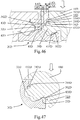
- Fig. 49 shows another embodiment base on the fifth embodiment, wherein the connector 20D' of this embodiment is the same as that in the fifth embodiment, and comprises a base board 21D' and an upright portion 22D' extends from the base board 21D'.
- the base board 21D' has a bottom face 210D' and two side faces 211D'.
- the base board 21D' of the connector 20D' has a locking member 23D' on the top of each of the two sides thereof.
- a locking piece 24D' extends laterally from each of two sides of the upright portion 22D'.
- the locking pieces 24D' each have a side face 240D'.
- the upright portion 22D' has a top face 220D'.
- an engaging slot 40D' is defined between the locking piece 24D' of the upright portion 22D' and the locking member 23D' of the base board 21D'.
- the engaging slot 40D' defines a top wall 41D' in the bottom of the locking piece 24D'.
- the upright portion 22D' has an inside wall 42D' formed in each of two sides thereof.
- the base board 21D' has a lower recess 400D' defined in the top face of each of two sides thereof.
- the locking member 23D' is located between the lower recess 400D' and the side face 211D'.
- the locking member 23D' has a wedge-shaped cross section.
- the lower recess 400D' has an inclined wall 410D' formed at the inside thereof and facing the locking member 23D'.
- a first ridge 43D' extends between the top wall 41D' and the inside wall 42D', the first ridge 43D' has an engaging face 431D' at the underside thereof, and a contact face 432D' is formed on a side of the first ridge 43D'.
- a top bump 60D' is formed between the inside wall 42D' and the inclined wall 410D' of the lower recess 400D'.
- a side inclined face 601D' is connected between the outside of the top bump 60D' and the inclined wall 410D' of the lower recess 400D'.
- a top inclined face 602D' is defined between the top of the top bump 60D' and the inside wall 42D'.
- the distance between the side faces 240D' of the two locking pieces 24D' of the upright portion 22D' of the connector 20D' is smaller than that between the side faces 211D' of the base board 21D'.
- An inclined guide face 420D' is formed on the outside of the locking member 23D' and located between the highest point of the locking member 23D' and the side face 211D' of the base board 21D'.
- Three grooves 212D' are defined in the bottom face 210D' of the base board 21D' and located along the longitudinal direction of the panel 20D'.
- the side faces 211D' of the base board 21D' of the connector 20D' are two recessed walls which save the use of material and also increase flexibility of the locking member 23D' of the base board 21D'.
- An inclined face is connected between the side face 240D' of the locking piece 24D' of the connector 20D' and the top face 220D'.
- An inclined face is connected between the side face 240D' of the locking piece 24D' of the connector 20D' and the top wall 41D'.
- An inclined face is connected between the engaging face 431D' of the first ridge 43D' of the connector 20D' and the contact face 432D'.
- the inclined faces mentioned above provide a good transition of the engagement between the panel 10D' and the connector 20D', so that the connection between the panel 10D' and the connector 20D' is smooth with less interference.
- a space 80D' is defined between the base board 21D' of the connector 20D' and the upright portion 22D', another space 82D' is defined between the upright portion 22D' and the locking piece 24D'.
- the two spaces 80D', 82D' save the use of material and make the connector 20D' be light in weight.
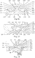
- Fig. 50 which shows another embodiment based on the fifth embodiment, wherein the panel 10D' has a first surface, a second surface located corresponding to the first surface, and a side.
- the panel 10D' comprises a groove 33D' defined in the side having the tongue 30D', the groove 33D' has an inner side 330D'.
- a top protrusion 70D' extends outward from the side having the groove 33D'.
- the top protrusion 70D' has an end face 701D' and a bottom face 702D'.
- the second surface of each panel 10D' has a slot 72D' defined in one side thereof.
- the slot 72D' has an inside 721D' which faces the side having the slot 72D'.
- a tongue 30D' is formed between the groove 33D' and the slot 72D'.
- the tongue 30D' has a tongue top face 31D' which faces the groove 33D', and the tongue 30D' has a tongue outer face 32D' which faces the side having the groove 33D'.
- the tongue outer face 32D' does not protrude beyond the end face 701D' of the top protrusion 70D'.
- the tongue 30D' is engaged with the engaging slot 40D' of the connector 20D' when the panel 10D' is connected to the connector 20D'.
- the tongue 30D' has a lower protrusion 300D' which is received in the lower recess 400D' of the connector 20D'.
- An inner inclined wall 302D' is formed at the inside of the lower protrusion 300D' and faces the slot 72D'.
- a first stepped portion 34D' is formed between the tongue top face 31D' and the inner side 330D'.
- the first stepped portion 34D' has an engaging face 341D' on the top thereof.
- the first stepped portion 34D' has a contact face 342D' which faces the side of the panel 10D'.
- a top recess 51D' is formed between the tongue outer face 32D' and the inner inclined wall 302D' of the lower protrusion 300D'.
- a top inclined face 511D' is connected between the outside of the top recess 51D' and the tongue outer face 32D'.
- An outer inclined face 512D' is connected between the top inclined face 511D' and the outer inclined face 512D'.
- An inclined face is formed between the first surface of the panel 10D' and the end face 701D'.
- a curved face is formed between end face 701D' of the top protrusion 70D' of the panel 10D' and the bottom face 702D'.
- An inclined face is formed between the engaging face 341D' of the first stepped portion 34D' of the panel 10D' and the contact face 342D'.
- Another inclined face is formed between the tongue top face 31D' of the tongue 30D' of the panel 10D' and the tongue outer face 32D'.
- the inner inclined wall 302D' of the lower protrusion 300D' is an inclined wall.
- the outer inclined face 512D' and the top inclined face 511D' each are an inclined face.
- Figs. 50 to 53 and 55 is an embodiment based on the fifth embodiment disclosed in Fig. 49 , the steps for connecting the panels 10D' and the connector 20D' are the same as those in the fifth embodiment, and will not describe again.
- Fig. 54 shows that when the panel 10D' having the tongue 30D' is pressed downward along the arrow head, the material below the engaging slot 40D' is deformed which is shown by the dotted line and the solid line in Fig. 54 .
- the tongue 30D' When the material below the engaging slot 40D' is deformed, the tongue 30D' to move downward relative to the engaging slot 40D', and the tongue outer 32D' of the tongue 30D' is offset from contact face 432D' of the first ridge 43D', and the contact face 342D' of the first stepped portion 34D' is offset from the side face 240D', the lower protrusion 300D' of the tongue 30D' is engaged with the lower recess 400D' of the engaging slot 40D' by the guidance of the inner inclined face 302D' of the lower protrusion 300D' and the inclined wall 410D' of the engaging slot 40D'.
- the top bump 60D' is engaged with the top recess 51D' of the tongue 30D'.
- the locking member 23D' is locked in the slot 72D'.
- the material below the engaging slot 40D' bounces back by the natural flexibility thereof, the engaging face 341D of the first stepped portion 34D' contacts the underside of the top wall 41D' of the locking piece D'.
- the tongue top face 31D' of the tongue 30D' of the tongue 30D contacts the underside of the engaging face 431D' of the first ridge 43D'.
- the tongue 30D' is then engaged with the engaging slot 40D' so that the panel 10D' does not disengaged from the connector 20D' as shown in Fig. 55 .
- the tongue 30D' When the material below the engaging slot 40D' is deformed, the tongue 30D' to move downward relative to the engaging slot 40D', and the tongue outer 32D' of the tongue 30D' is offset from contact face 432D' of the first ridge 43D', and the contact face 342D' of the first stepped portion 34D' is offset from the side face 240D', because the inclined face is formed between the engaging face 341D' of the first stepped portion 34D' of the panel 10D' and the contact face 342D', the inclined face is formed between the side face 240D' of the locking piece 24D' of the panel 10D' and the top wall 41D', the inclined face is formed between the tongue top face 31D' of the tongue 30D' of the panel 10D' and the tongue outer face 32D', and the inclined face is formed between the engaging face 431D' of the first ridge 43D' of the connector 20D' and the contact face 432D', so that the panel 10D' can easily move relative to the connector 20D
- Fig. 55 shows that the two panels 10D' are connected to the connector 20D'.
- the side of the panel 10D' that is located remote from the connector 20D' is lifted to let the lower protrusion 300D' of the tongue 30D' push the inclined wall 410D' to deform the connector 20D' as shown in Fig. 54 .
- the lower protrusion 300D' of the tongue 30D' is then disengaged from the lower recess 400D' of the connector 20D', and the tongue 30D' is disengaged from the engaging slot 40D'.
- the top protrusions 70D' of the two panels 10D' contact each other to form the fulcrum about which the panels 10D' are pivoted.
- the inclined face is formed between the first surface of the panel 10D' and the end face 701D', so that the side of the first surface of the panel 10D' is avoided from being damaged when the panel 10D' is pivoted.
- the curved face is formed between the end face 701D' of the top protrusion 70D' of the panel 10D' and the bottom face 702D', the curved face avoids the panel 10D' from being interfered by the top face 220D' of the connector 20D' when the panel 10D' is pivoted.
- the sixth embodiment is based on the third embodiment, wherein the connector 20E is disclosed in Fig. 56 and comprises a base board 21E and an upright portion 22E extends from the base board 21E.
- the base board 21E has a bottom face 210E and two side faces 211E.
- the base board 21E of the connector 20E has a locking member 23E on the top of each of the two sides thereof.
- a locking piece 24E extends laterally from each of two sides of the upright portion 22E.
- the locking pieces 24E each have a side face 240E.
- the upright portion 22E has a top face 220E. In this embodiment, there are two grooves 221E defined in the top face 220E.
- An engaging slot 40E is defined between the locking piece 24E of the upright portion 22E and the locking member 23E of the base board 21E.
- the engaging slot 40E defines a top wall 41E in the bottom of the locking piece 24E.
- the upright portion 22E has an inside wall 42E formed in each of two sides thereof.
- the base board 21E has a lower recess 400E defined in the top face of each of two sides thereof.
- the locking member 23E is located between the lower recess 400E and the side face 211E.
- the locking member 23E has a wedge-shaped cross section.
- the lower recess 400E has an inclined wall 410E formed at the inside thereof and facing the locking member 23E.
- a first ridge 43E extends between the top wall 41E and the inside wall 42E, the first ridge 43E has an engaging face 431E at the underside thereof, and a contact face 432E is formed on a side of the first ridge 43E.
- a top bump 60E is formed between the inside wall 42E and the inclined wall 410E of the lower recess 400E.
- a side inclined face 601E is connected between the outside of the top bump 60E and the inclined wall 410E of the lower recess 400E.
- a top inclined face 602E is defined between the top of the top bump 60E and the inside wall 42E.
- a notch 603E is formed between the side inclined face 601E and the top inclined face 602E.
- Fig. 56 shows that the distance between the side faces 240E of the two locking pieces 24E of the upright portion 22E of the connector 20E is smaller than that between the side faces 211E of the base board 21E.
- An inclined guide face 420E is formed on the outside of the locking member 23E and located between the highest point of the locking member 23E and the side face 211E.
- Two grooves 212E are defined in the bottom face 210E of the base board 21E and located along the longitudinal direction of the panel 20E.
- the inclined wall 410E of the lower recess 400 that is located close to the inside of the locking member 23 is an inclined wall.
- the notch 603E between the side inclined face 601E and the top inclined face 602E properly adjust the force to deform the base board 21E.
- the panel 10E of sixth embodiment of the present invention comprises a groove 33E defined in the side having the tongue 30E, the groove 33E has an inner side 330E.
- a top protrusion 70E extends outward from the side having the groove 33E.
- the top protrusion 70E has an end face 701E and a bottom face 702E.
- the second surface of the panel 10E has a slot 72E defined in one side thereof.
- the slot 72E has an inside 721E which faces the side having the slot 72E.
- a tongue 30E is formed between the groove 33E and the slot 72E.
- the tongue 30E has a tongue top face 31E which faces the groove 33E, and the tongue 30E has a tongue outer face 32E which faces the side having the groove 33E.
- the tongue outer face 32E does not protrude beyond the end face 701E of the top protrusion 70E.
- the tongue 30E is engaged with the engaging slot 40E of the connector 20E when the panel 10E is connected to the connector 20E.
- the tongue 30E has a lower protrusion 300E which is received in the lower recess 400E of the connector 20E.
- An inner inclined wall 302E is formed at the inside of the lower protrusion 300E and faces the slot 72E.
- a first stepped portion 34E is formed between the tongue top face 31E and the inner side 330E.
- the first stepped portion 34E has an engaging face 341E on the top thereof.
- the first stepped portion 34E has a contact face 342E which faces the side of the panel 10E.
- a top recess 51E is formed between the tongue outer face 32E and the inner inclined wall 302E of the lower protrusion 300E.
- a top inclined face 511E is connected between the outside of the top recess 51E and the tongue outer face 32E.
- An outer inclined face 512E is connected between the inside of the top recess 51E and the inner inclined wall 302E.
- Each of the inner inclined face 302B of the lower protrusion 300B of the panel 10B, the top inclined face 511E and the outer inclined face 512E of the top recess 51E is an inclined face.
- FIG. 57 shows that the panel 10E on the left is connected to the connector 20E, and the panel 10E on the right having the tongue 30E on the right is moved toward the connector 20E with the engaging slot 40E on the same plane with the panel 10E.
- At least one side of the contact position is an inclined face or a curved face, so that the inclined face guides the panel 10E to change its height relative to the side of the connector 20E.
- Fig. 57 shows that the panel 10E having the tongue 30E is guided by the inclined face and lifted up.
- the horizontal distance L1E between a vertical extension line of the lowest point of the lower protrusion 300E of the tongue 30E of the panel 10E and a vertical extension line of the highest point of the tongue outer face 32E of the lower tongue 30E is smaller than the horizontal distance L2E between a vertical extension line of the highest point of the locking member 23E of the connector 20E and a vertical extension line of the lowest point of the contact face 432E of the first ridge 43E.
- Fig. 58 is used to describe the steps for moving the panels 10E toward the connector 20E.
- the panel 10E on the right is moved downward a little bit due to the gravity to allow the inner inclined face 302E of the lower protrusion 300E of the tongue 30E to contact the inclined wall 410E of the lower recess 400E of the connector 20E.
- the contact face 432E of the first ridge 43E of the panel 10E contacts the tongue outer face 32E of the tongue 30E, and/or before the contact face 342E of the first ridge 34E contacts the side face 240E of the locking piece 24E
- the panel 10E contacts the connector 20E by the inclined face which makes the movement of the panel 10E be easy without using any tool to force the panel 10E to move.
- the horizontal distance L1E between a vertical extension line of the lowest point of the lower protrusion 300E of the tongue 30E of the panel 10E and a vertical extension line of the highest point of the tongue outer face 32E of the tongue 30E is larger than the horizontal distance L4E between a vertical extension line of the lowest point of the inclined wall 410E of the engaging slot 40E and a vertical extension line of the lowest point of the contact face 432E of the first ridge 43E.
- the horizontal distance L5E between a vertical extension line of the inner side 330E of the panel 10E and the vertical line of the outside of the contact face 342E of the first stepped portion 34E is smaller than the horizontal distance L6E between a vertical extension line of the outside of the side face 240E of the engaging slot 40E of the connector 20E and the vertical line of the highest point of the inside wall 42E of the engaging slot 40E.
- the horizontal distance L7E between a vertical extension line of the inner side 330E of the panel 10E and the vertical line of highest point of the tongue outer face 32E is larger than the horizontal distance L8E between a vertical extension line of an outside of the side face 240E of the connector 20E and the vertical line of the lowest point of the contact wall 432E of the first ridge 43E. As shown in Fig. 59 , L7E>L8E.
- the contact face 32E of the tongue 30E contacts the contact face 432E of the first ridge 43E, and the contact face 342E of the first stepped portion 34E contacts the side face 240E, so that the panel 10E and the connector 20E cannot be moved toward on the same plane.
- the inner inclined face 302E of the lower protrusion 300E of the tongue 30E pushes the inclined wall 410E of the engaging slot 40E to deform the material below the engaging slot 40E such that the tongue 30E is able to move downward and into the engaging slot 40E.
- the top bump 60E is engaged with the top recess 51E of the tongue 30E.
- the locking member 23E is locked in the slot 72E.
- the material below the engaging slot 40E bounces back by the natural flexibility thereof, the engaging face 341E of the first stepped portion 34E contacts the underside of the top wall 41E of the locking piece 24E.
- the tongue top face 31E of the tongue 30E contacts the underside of the engaging face 431E of the first ridge 43E.
- the tongue 30E is then engaged with the engaging slot 40E so that the panel 10E does not disengaged from the connector 20E as shown in Fig. 61 .
- the tongue top face 31E of the tongue 30E contacts the engaging face 431E of the first ridge 43E.
- the engaging face 341E of the first stepped portion 34E of the tongue 30E contacts the top wall 41E of the locking piece 24E.
- the locking member 23E is engaged with the slot 72E.
- the inner inclined face 302E of the lower protrusion 300E of the tongue 30E contacts the inclined wall 410E of the engaging slot 40E.
- the tongue 30E is engaged with the engaging slot 40E because that the material below the engaging slot 40E is deformed.
- the material below the engaging slot 40E After the tongue 30E is engaged with the engaging slot 40E, the material below the engaging slot 40E returns to its initial status, the distance between the outside of the outside of the engaging face 341E of the first stepped portion 34E and any point of the contact area between the inclined wall 410E and the inner inclined face 302E is larger than the distance between the intersection point between the engaging face 431E of the first ridge 43E of the engaging slot 40E and the contact face 432E to the correspondent contact portion of the inclined wall 410E.
- the tongue 30E of the second embodiment cannot be engaged with the engaging slot 40E if the material below the engaging slot 40E is not deformed, so that the tongue 30E is securely connected with the engaging slot 40E.
- Fig. 62 shows that holes 604E are drilled in the top bump 60E of the connector 20E as needed, the holes 604E are drilled at the portions where the notch 603E is located.
- the drill is easily guided to the notch 603E to easily drill the holes 604E.
- the holes 604E are drilled for securing the connector 10E.
- the heads of the nails 90E are accommodated in the top bump 60E when the nails 90E are nailed.
- the connector 20F for being connected with the panels 10F is the same as the connector 20D' in Fig. 49 , and the connector 20F comprises a base board 21F and an upright portion 22F extends from the base board 21F.
- the base board 21F has a bottom face 210F and two side faces 211F.
- the base board 21F of the connector 20F has a locking member 23F on the top of each of the two sides thereof.
- a locking piece 24F extends laterally from each of two sides of the upright portion 22F.
- the locking pieces 24F each have a side face 240F.
- the upright portion 22F has a top face 220F. In this embodiment, there are three grooves 221F defined in the top face 220F.
- An engaging slot 40F is defined between the locking piece 24F of the upright portion 22F and the locking member 23F of the base board 21F.
- the engaging slot 40F defines a top wall 41F in the bottom of the locking piece 24F.
- the upright portion 22F has an inside wall 42F formed in each of two sides thereof.
- the base board 21F has a lower recess 400F defined in the top face of each of two sides thereof.
- the locking member 23F is located between the lower recess 400F and the side face 211F.
- the locking member 23F has a wedge-shaped cross section.
- the lower recess 400F has an inclined wall 410F formed at the inside thereof and facing the locking member 23F.
- a first ridge 43F extends between the top wall 41F and the inside wall 42F, the first ridge 43F has an engaging face 431F at the underside thereof, and a contact face 432F is formed on a side of the first ridge 43F.
- a top bump 60F is formed between the inside wall 42F and the inclined wall 410F of the lower recess 400F.
- a side inclined face 601F is connected between the outside of the top bump 60F and the inclined wall 410F of the lower recess 400F.
- a top inclined face 602F is defined between the top of the top bump 60F and the inside wall 42F.
- the distance between the side faces 240F of the two locking pieces 24F of the upright portion 22F of the connector 20F is smaller than that between the side faces 211F of the base board 21F.
- An inclined guide face 420F is formed on the outside of the locking member 23F and located between the highest point of the locking member 23F and the side face 211F.
- Three grooves 212F are defined in the bottom face 210F of the base board 21F and located along the longitudinal direction of the panel 20F.
- the side faces 211F of the base board 21F of the connector 20F are two recessed walls which save the use of material and also increase flexibility of the locking member 23F of the base board 21F.
- An inclined face is connected between the side face 240F of the locking piece 24F of the connector 20F and the top face 220F.
- An inclined face is connected between the side face 240F of the locking piece 24F of the connector 20F and the top wall 41F.
- An inclined face is connected between the engaging face 431F of the first ridge 43F of the connector 20F and the contact face 432F.
- the connector 20F is made by plastic and a space 80F is defined between the base board 21F of the connector 20F and the upright portion 22F, another space 82F is defined between the upright portion 22F and the locking piece 24F.
- the two spaces 80F, 82F save the use of material and make the connector 20F be light in weight.
- a buffering layer is attached to the surface of the engaging slot 40F of the connector 20F, and the buffering layer is also attached on the surface of each of the inclined wall 410F, the side inclined face 601F, the top inclined face 602F, the inside wall 42F, the engaging face 431F and the top wall 41F. Besides, the buffering layer is also attached on the surface of the side face 240F of the locking piece 24F.
- the buffering layer is made by the material that is softer than that of the connector 20F so that the connector 20F is able to be deformed as desired when the panel 10F is connected with the connector 20F.
- the buffering layer provides a buffering feature between the panels 10F and the connector 20F to reduce the friction between the panels 10F and the connector 20F to solve the problems of shrinking and expanding due to change of temperature or the problems of shifting due to pushing to generate noise.
- the buffering layer is made by soft material so that the buffering layer can be made with the connector 20F by way of double-layer extruding.
- Fig. 65 discloses another embodiment which is based on the seventh embodiment, wherein the connector 20F' is the same as the connector 20F disclosed in the Fig. 64 , the only difference is that the buffering layer on the surface of the engaging slot 40F' is also attached on the surface of each of the inclined wall 410F', the side inclined face 601F', the top inclined face 602F', the inside wall 42F', the engaging face 431F', contact face 432F', the top wall 41F' and the side face 240F'. Furthermore, the buffering layer is attached on the surface of each of the top face 220F' of the upright portion 22F' and the groove 221F' of the top face 220F'.
- Fig. 66 discloses the eighth embodiment, wherein the connector 20G basically the same as the connector 20F' in Fig. 65 , and comprises a base board 21G and an upright portion 22G extends from the base board 21G.
- the base board 21G has a bottom face 210G and two side faces 211G.
- the base board 21G of the connector 20G has a locking member 23G on the top of each of the two sides thereof.
- a locking piece 24G extends laterally from each of two sides of the upright portion 22G.
- the locking pieces 24G each have a side face 240G.
- the upright portion 22G has a top face 220G. In this embodiment, there are two grooves 221G defined in the top face 220G.
- An engaging slot 40G is defined between the locking piece 24G of the upright portion 22G and the locking member 23G of the base board 21G.
- the engaging slot 40G defines a top wall 41G in the bottom of the locking piece 24G.
- the upright portion 22G has an inside wall 42G formed in each of two sides thereof.
- the base board 21G has a lower recess 400G defined in the top face of each of two sides thereof.
- the locking member 23G is located between the lower recess 400G and the side face 211G.
- the locking member 23G has a wedge-shaped cross section.
- the lower recess 400G has an inclined wall 410G formed at the inside thereof and facing the locking member 23G.
- a first ridge 43G extends between the top wall 41G and the inside wall 42G, the first ridge 43G has an engaging face 431G at the underside thereof, and a contact face 432G is formed on a side of the first ridge 43G.
- a top bump 60G is formed between the inside wall 42G and the inclined wall 410G of the lower recess 400G.
- a side inclined face 601G is connected between the outside of the top bump 60G and the inclined wall 410G of the lower recess 400G.
- a top inclined face 602G is defined between the top of the top bump 60G and the inside wall 42G.
- the distance between the side faces 240G of the two locking pieces 24G of the upright portion 22G of the connector 20G is smaller than that between the side faces 211G of the base board 21G.
- An inclined guide face 420G is formed on the outside of the locking member 23G and located between the highest point of the locking member 23G and the side face 211G.
- Three grooves 212G are defined in the bottom face 210G of the base board 21G and located along the longitudinal direction of the panel 20G.
- the side faces 211G of the base board 21G of the connector 20G are two recessed walls which save the use of material and also increase flexibility of the locking member 23G of the base board 21G.
- An inclined face is connected between the side face 240G of the locking piece 24G of the connector 20G and the top face 220G.
- An inclined face is connected between the side face 240G of the locking piece 24G of the connector 20G and the top wall 41G.
- An inclined face is connected between the engaging face 431G of the first ridge 43G of the connector 20G and the contact face 432G.
- the connector 20G is made by plastic and a space 80G is defined between the base board 21G of the connector 20G and the upright portion 22G.
- the space 80G saves the use of material and make the connector 20G be light in weight.
- the top face 220G of the upright portion 22G of the connector 20G has a central groove 84G which allows the locking piece 24G and the first ridge 43G to be resiliently deformed.
- the central groove 84G is designed to increase the flexibility of the locking piece 24G and the first ridge 43G, so that when the tongue is engaged with the engaging slot 40G of the connector 20G, the material under the engaging slot 40 is deformed, and the locking piece 24G and the first ridge 43G are also deformed. This make the connection between the panels and the connector 20G be easy and convenient.
- the central groove 84G also saves the use of material of the connector 20G to decrease the weight of the connector 20G.
- a buffering layer is attached to the surface of the engaging slot 40G of the connector 20G, and the buffering layer is also attached on the surface of each of the inclined wall 410G, the side inclined face 601G, the top inclined face 602G, the inside wall 42G, the engaging face 431G, the contact face 432G, the top wall 41G, the side face 240G and the top face 220G of the upright portion 22G.
- the buffering layer is attached to the surface of the groove 221G of the top face 220G.
- the buffering layer is made by the material that is softer than that of the connector 20G so that the connector 20G is able to be deformed as desired when the panel 10G is connected with the connector 20G.
- the buffering layer provides a buffering feature between the panels 10G and the connector 20G to reduce the friction between the panels 10G and the connector 20G to solve the problems of shrinking and expanding due to change of temperature or the problems of shifting due to pushing to generate noise.
- the buffering layer is made by soft material so that the buffering layer can be made with the connector 20G by way of double-layer extruding.
- Fig. 67 shows the embodiment based on the embodiment disclosed in Fig. 49
- Fig. 68 shows the embodiment based on the embodiment disclosed in Fig. 64
- Fig. 69 shows the embodiment based on the embodiment disclosed in Fig. 65 .
- the top face 220H of the locking piece 24H of the connector 20H has a buffering plate 226H extending from the center thereof.
- the top face 220H' of the locking piece 24H' of the connector 20H' has a buffering plate 226H' extending from the center thereof.
- the top face 220H" of the locking piece 24H" of the connector 20H" has a buffering plate 226H" extending from the center thereof.
- the connector 20H" basically the same as that in the Fig. 65 , the difference is that the top face 220H" of the locking piece 24H" of the connector 20H” has a buffering plate 226H" extending from the center thereof.
- the buffering plate 226H” is made by the material that is softer than the material of the connector 20H' so that the buffering plate 226H" can be made with the connector 20G by way of double-layer extruding.
- the buffering plate 226H” When the connection 20H" is connected with the panels on two sides of the connector 20H", the buffering plate 226H” is clamped between the top protrusions of the two panels to provide a separation between the top protrusions of the two panels.
- the buffering plate 226H” fills the space between the top protrusions of the two panels, and also ensures that there will be no noise generated due to friction between the top protrusions of the two panels.
- Fig. 70 discloses the panel 101 which is a triangular panel which has a first surface, a second surface which is located opposite to the first surface, and three sides, wherein at least two of the three sides has a tongue 301.
- the panels 101 are cooperated with the connectors 201 to be arranged to form a specific pattern.
- the panels 101 do not need to lift one side thereof so that the pattern as disclosed in Fig. 72 can be made.
- the panels 10i and the connector 20i ca be cooperated with the tongues and engaging slots of the multiple embodiments described above to achieve the purpose of the present invention.
- Figs. 73 and 74 show the panels are connected to each other, wherein the third embodiment is taken as an example to describe. Because the panels 10B and the connectors 20B are connected to each other by way of pressing, so that the connector 30B are respectively located on the four sides of the panels, and the panels 20B are easily connected to each other by the connectors 30B.
- Fig. 75 shows the elongate panels are connected to each other along the longitudinal direction thereof.
- Fig. 76 shows that four elongate panels are connected to each other to form a unit, and four units are composed to form a square combination.
- Fig. 77 shows that multiple panels are connected to each other to form a transverse S shape combination. Because the panels are connected to the connectors of the present invention by way of pressing, the tongues of the panels are engaged with the engaging slots of the connectors without lifting one side of the panels, so that the panels can be connected to each other in different ratios of the length-and-width to form desired patterns and shapes.
Landscapes
- Engineering & Computer Science (AREA)
- Architecture (AREA)
- Civil Engineering (AREA)
- Structural Engineering (AREA)
- Floor Finish (AREA)
- Connection Of Plates (AREA)
- Connector Housings Or Holding Contact Members (AREA)
Claims (48)
- Fußbodensystem, wobei die Verbesserungen Folgendes umfassen:- ein Verbindungselement und- mehrere Platten (10, 10A, 10B, 10C, 10D, 10E, 10I), die miteinander verbunden sind, wobei jede der Platten eine erste Oberfläche, eine zweite Oberfläche, die an einer der ersten Oberfläche zugeordneten Stelle angeordnet ist, und mindestens drei Seiten, wobei mindestens zwei Seiten davon jeweils eine Feder (30, 30A, 30B, 30C, 30D, 30E, 30I) aufweist,wobei jede der Platten (10, 10A, 10B, 10C, 10D, 10E, 10I) eine in der Seite mit der Feder (30, 30A, 30B, 30C, 30D, 30E, 30I) vorgesehene Nut (33, 33A, 33B, 33C, 33D, 33E) aufweist, wobei jede Nut (33, 33A, 33B, 33C, 33D, 33E) eine Innenseite (330, 330A, 330B, 330C, 330D, 330E) hat, wobei sich eine obere Ausbuchtung (70, 70A, 70B, 70C, 70D, 70E) ausgehend von der Seite mit der Nut (33, 33A, 33B, 33C, 33D, 33E) nach außen erstreckt und oberhalb der Nut (33, 33A, 33B, 33C, 33D, 33E) befindet, wobei jede obere Ausbuchtung (70, 70A, 70B, 70C, 70D, 70E) eine Stirnseite (701, 701A, 701B, 701C, 701D, 701E) und eine Bodenseite (702, 702A, 702B, 702C, 702D, 702E) hat, wobei die zweite Oberfläche jeder der Platten (10, 10A, 10B, 10C, 10D, 10E, 10I) einen in einer der Seiten davon vorgesehenen Schlitz (72, 72A, 72B, 72C, 72D, 72E) aufweist und jeder Schlitz (72, 72A, 72B, 72C, 72D, 72E) eine der Seite mit dem Schlitz (72, 72A, 72B, 72C, 72D, 72E) zugewandt angeordnete innere Seite (721, 721A, 721B, 721C, 721D, 721E) aufweist, wobei eine Feder (30, 30A, 30B, 30C, 30D, 30E, 30I) zwischen der Nut (33, 33A, 33B, 33C, 33D, 33E) und dem Schlitz (72, 72A, 72B, 72C, 72D, 72E) ausgebildet ist, wobei jede Feder (30, 30A, 30B, 30C, 30D, 30E, 30I) eine untere Ausbuchtung (300, 300A, 300B, 300C, 300D, 300E) aufweist, wobei jede Feder (30, 30A, 30B, 30C, 30D, 30E, 30I) eine Feder-Oberseite (31, 31A, 31B, 31C, 31D, 31E) aufweist, die der Nut (33, 33A, 33B, 33C, 33D, 33E) zugewandt angeordnet ist, wobei jede Feder (30, 30A, 30B, 30C, 30D, 30E, 30I) eine Feder-Außenseite (32, 32A, 32B, 32C, 32D, 32E) aufweist, die der Seite mit der Nut (33, 33A, 33B, 33C, 33D, 33E) zugewandt angeordnet ist, wobei die Feder-Außenseite (32, 32A, 32B, 32C, 32D, 32E) nicht über die Stirnseite (701, 701A, 701B, 701C, 701D, 701E) der oberen Ausbuchtung (70, 70A, 70B, 70C, 70D, 70E) hervorsteht, wobei eine äußere Schrägfläche (301, 301A, 301B, 301C, 301D, 301E) zwischen einer äußeren Seite der unteren Ausbuchtung (300, 300A, 300B, 300C, 300D, 300E) und der Feder-Außenseite (32, 32A, 32B, 32C, 32D, 32E) zwischengeschaltet ist, wobei eine innere Schrägfläche (302, 302A, 302B, 302C, 302D, 302E) an einer inneren Seite der unteren Ausbuchtung (300, 300A, 300B, 300C, 300D, 300E) ausgebildet und dem Schlitz (72, 72A, 72B, 72C, 72D, 72E) zugewandt angeordnet ist, wobei es sich bei dem Verbindungselement (20, 20A, 20B, 20C, 20D, 20E, 20F, 20G, 20H, 20I) um ein längliches Verbindungselement handelt, das ein symmetrisches oberes Ende aufweist, wobei das Verbindungselement (20, 20A, 20B, 20C, 20D, 20E, 20F, 20G, 20H, 20I) eine Grundplatte (21, 21A, 21B, 21C, 21D, 21E, 21F, 21G) an einem unteren Ende davon aufweist, wobei sich ein aufrechter Abschnitt (22, 22A, 22B, 22C, 22D, 22E, 22F, 22G) ausgehend von der Grundplatte (21, 21A, 21B, 21C, 21D, 21E, 21F, 21G) erstreckt, wobei die Grundplatte (21, 21A, 21B, 21C, 21D, 21E, 21F, 21G) eine Bodenseite (210, 210A, 210B, 210C, 210D, 210E, 210F, 210G) und zwei Seitenflächen (211, 211A, 211B, 211C, 211D, 211E, 211F, 211G) aufweist, wobei die Grundplatte (21, 21A, 21B, 21C, 21D, 21E, 21F, 21G) ein Verriegelungsglied (23, 23A, 23B, 23C, 23D, 23E, 23F, 23G) auf einer oberen Seite jeder der beiden Seiten davon aufweist, wobei sich ein Verriegelungsstück (24, 24A, 24B, 24C, 24D, 24E, 24F, 24G) seitlich von jeder der beiden Seiten des aufrechten Abschnitts (22, 22A, 22B, 22C, 22D, 22E, 22F, 22G) erstreckt, wobei das Verriegelungsstück (24, 24A, 24B, 24C, 24D, 24E, 24F, 24G) eine Seitenfläche (240, 240A, 240B, 240C, 240D, 240E, 240F, 240G) aufweist, wobei der aufrechte Abschnitt (22, 22A, 22B, 22C, 22D, 22E, 22F, 22G) eine Oberseite (220, 220A, 220B, 220C, 220D, 220E, 220F, 220G) aufweist, wobei ein Eingriffsschlitz (40, 40A, 40B, 40C, 40D, 40E, 40F, 40G) zwischen dem Verriegelungsstück (24, 24A, 24B, 24C, 24D, 24E, 24F, 24G) des aufrechten Abschnitts (22, 22A, 22B, 22C, 22D, 22E, 22F, 22G) und dem Verriegelungsglied (23, 23A, 23B, 23C, 23D, 23E, 23F, 23G) der Grundplatte (21, 21 A, 21B, 21C, 21D, 21E, 21F, 21G) vorgesehen ist, wobei der Eingriffsschlitz (40, 40A, 40B, 40C, 40D, 40E, 40F, 40G) eine obere Wand (41, 41A, 41B, 41C, 41D, 41E, 41F, 41G) in einem Boden des Verriegelungsstücks (24, 24A, 24B, 24C, 24D, 24E, 24F, 24G) ausbildet, wobei der aufrechte Abschnitt (22, 22A, 22B, 22C, 22D, 22E, 22F, 22G) eine in jeder der beiden Seiten davon ausgebildete Innenwand (42, 42A, 42B, 42C, 42D, 42E, 42F, 42G) aufweist, wobei die Grundplatte (21, 21A, 21B, 21C, 21D, 21E, 21F, 21G) eine in einer Oberseite jeder der beiden Seiten davon vorgesehene untere Einbuchtung (400, 400A,400B, 400C, 400D, 400E, 400F, 400G) aufweist, wobei das Verriegelungsglied (23, 23A, 23B, 23C, 23D, 23E, 23F, 23G) zwischen der unteren Einbuchtung (400, 400A, 400B, 400C, 400D, 400E, 400F, 400G) und der Seitenfläche (211, 211A, 211B, 211C, 211D, 21 IE, 211F, 211G) des Verbindungselements angeordnet ist, wobei das Verriegelungsglied (23, 23A, 23B, 23C, 23D, 23E, 23F, 23G) einen keilförmigen Querschnitt aufweist, wobei die untere Einbuchtung (400, 400A, 400B, 400C, 400D, 400E, 400F, 400G) eine an der inneren Seite des Verriegelungsglieds (23, 23A, 23B, 23C, 23D, 23E, 23F, 23G) ausgebildete schräge Wand (410, 410A, 410B, 410C, 410D, 410E, 410F, 410G) aufweist,
dadurch gekennzeichnet, dass
mindestens ein erster stufenförmiger Abschnitt (34, 34A, 34B, 34C, 34D, 34E) der Platten (10, 10A, 10B, 10C, 10D, 10E, 10I) zwischen der Feder-Oberseite (31, 31A, 31B, 31C, 31D, 31E) und der Innenseite (330, 330A, 330B, 330C, 330D, 330E) ausgebildet ist, wobei jeder des mindestens einen ersten stufenförmigen Abschnitts (34, 34A, 34B, 34C, 34D, 34E) eine Eingriffsfläche (341, 341B, 341C, 341D, 341E) auf einer oberen Seite davon aufweist, wobei jeder des mindestens einen ersten stufenförmigen Abschnitts (34, 34A, 34B, 34C, 34D, 34E) eine Kontaktfläche (342, 342B, 342C, 342D, 342E) aufweist, der der Seite mit der Nut (33, 33A, 33B, 33C, 33D, 33E) zugewandt angeordnet ist, und dass
sich eine erste Rippe (43A, 43B, 43C, 43D, 43E, 43F, 43G) des Verbindungselements 20, 20A, 20B, 20C, 20D, 20E, 20F, 20G, 20H, 20I) zwischen der oberen Wand (41A, 41B, 41C, 41D, 41E, 41F, 41G) und der Innenwand (42A, 42B, 42C, 42D, 42E, 42F, 42G) erstreckt, welche erste Rippe (43A, 43B, 43C, 43D, 43E, 43F, 43G) eine an der Unterseite davon ausgebildete Eingriffsfläche (431A, 431B, 431C, 431D, 431E, 431F, 431G) und eine an einer Seite davon ausgebildete Kontaktfläche (432A, 432B, 432C, 432D, 432E, 432F, 432G) aufweist. - Fußbodensystem nach Anspruch 1, wobei der erste stufenförmige Abschnitt (34C)
und ein zweiter stufenförmiger Abschnitt (35C) zwischen der Feder-Oberseite (31C) und der Innenseite (330C) der Nut (33, 33A, 33B, 33C, 33D, 33E) ausgebildet sind, wobei der erste stufenförmige Abschnitt (34C) die Eingriffsfläche (341C) auf der oberen Seite davon und die Kontaktfläche (342C) an der Seite davon aufweist, während der zweite stufenförmige Abschnitt (35C) eine Eingriffsfläche (351C) auf einer oberen Seite davon und eine Kontaktfläche (352C) an der Seite davon aufweist. - Fußbodensystem nach Anspruch 1, wobei eine obere Einbuchtung (51D, 51E) zwischen der Feder-Außenseite (32D, 32E) und der inneren Schrägfläche (302D, 302E) des unteren Abschnitts (300D, 300E) ausgebildet ist, wobei eine obere Schrägfläche (511D, 511E) zwischen einer äußeren Seite der oberen Einbuchtung (51D, 51E) und der Feder-Außenseite (32D, 32E) zwischengeschaltet ist, und wobei eine äußere Schrägfläche (512D, 512E) zwischen einer inneren Seite der oberen Einbuchtung (51D, 51E) und der inneren Schrägfläche (302D, 302E) zwischengeschaltet ist.
- Fußbodensystem nach Anspruch 1 oder 2, wobei es sich bei der äußeren Schrägfläche (301, 301A, 301B, 301C) der unteren Ausbuchtung (300, 300A, 300B, 300C) um eine gekrümmte Fläche handelt.
- Fußbodensystem nach Anspruch 1, wobei es sich bei der äußeren Schrägfläche (301B') des unteren Abschnitts (300B') um eine Schrägfläche handelt.
- Fußbodensystem nach Anspruch 1 oder 3, wobei es sich bei der inneren Schrägfläche (302, 302A, 302B, 302C, 302D) der unteren Ausbuchtung (300, 300A, 300B, 300C, 300D) um eine gekrümmte Fläche handelt.
- Fußbodensystem nach Anspruch 1 oder 3, wobei es sich bei der äußeren Schrägfläche (512D, 512E) der unteren Ausbuchtung (300D, 300E) um eine Schrägfläche handelt.
- Fußbodensystem nach Anspruch 1 oder 3, wobei es sich bei der inneren Schrägfläche (302E) der unteren Ausbuchtung (300E) um eine Schrägfläche handelt.
- Fußbodensystem nach Anspruch 1, wobei die Feder (30A') einen in einer Unterseite davon vorgesehenen elastischen Schlitz (305A') aufweist.
- Fußbodensystem nach Anspruch 1, wobei eine obere Beule (60D, 60E, 60F, 60G) zwischen der Innenwand (42D, 42E, 42F, 42G) und der schrägen Wand (410D, 410E, 410F, 410G) der unteren Einbuchtung (400D, 400E, 400F, 400G) ausgebildet ist, wobei eine seitliche Schrägfläche (601D, 601E, 601F, 601G) zwischen einer äußeren Seite der oberen Beule (60D, 60E, 60F, 60G) und der schrägen Wand (410D, 410E, 410F, 410G) zwischengeschaltet ist, und wobei eine obere Schrägfläche (602D, 602E, 602F, 602G) zwischen der oberen Seite der oberen Beule (60D, 60E, 60F, 60G) und der Innenwand (42D, 42E, 42F, 42G) zwischengeschaltet ist.
- Fußbodensystem nach Anspruch 10, wobei eine Kerbe (603E) zwischen der seitlichen Schrägfläche (601E) und der oberen Schrägfläche (602E) vorgesehen ist.
- Fußbodensystem nach Anspruch 1, 10 oder 11, wobei der aufrechte Abschnitt (22) mehrere Nuten (221, 222) aufweist, die in der Oberseite (220) angeordnet sind.
- Fußbodensystem nach Anspruch 1 oder 10, wobei die Oberseite (220C') des Verbindungselements (20C') eine Hauptnut (223C') aufweist und in einem inneren Ende der Hauptnut (223C') eine Nut (224C') vorgesehen ist.
- Fußbodensystem nach Anspruch 1 oder 10, wobei die Oberseite (220C ") des Verbindungselements (20C ") eine mittlere Nut (225C ") aufweist, die eine elastische Verformung des Verriegelungsstücks (24C") ermöglicht.
- Fußbodensystem nach Anspruch 1, 10, 11 oder 12, wobei die Bodenseite (210, 210A, 210B, 210C, 210D, 210E, 210F, 210G) der Grundplatte (21, 21A, 21B, 21C, 21D, 21E, 21F, 21G) mehrere Nuten (212, 212B, 212C, 212D, 212E, 212F 212G) aufweist, die sich entlang einer Längsrichtung des Verbindungsstücks (20, 20A, 20B, 20C, 20D, 20E, 20F, 20G) erstreckt.
- Fußbodensystem nach Anspruch 1, 10 , 11 oder 12, wobei die äußere Seite des Verriegelungsglieds (23) eine schräge Führungsfläche (420) aufweist, die zwischen einer obersten Stelle des Verriegelungsglieds (23) und der Seitenfläche (211) angeordnet ist.
- Fußbodensystem nach Anspruch 1, 10, 11 oder 12, wobei ein Abstand zwischen den beiden Seitenflächen (240) der beiden Verriegelungsstücke (24) des aufrechten Abschnitts (22) des Verbindungselements (20) geringer als der zwischen den Seitenflächen (211) der Bodenseite (210) der Grundplatte (21) ist.
- Fußbodensystem nach Anspruch 1, wobei ein Raum (80D') zwischen der Bodenplatte (21D') des Verbindungselements (20D') und dem aufrechten Abschnitt (22D') vorgesehen ist, wobei ein anderer Raum (82D') zwischen dem aufrechten Abschnitt (22D') und dem Verriegelungsstück (24D') vorgesehen ist.
- Fußbodensystem nach Anspruch 1 oder 18, wobei eine Schrägfläche zwischen der Seitenfläche (240D') des Verriegelungsstücks (24D') des Verbindungselements (20D') und der oberen Wand (41D') ausgebildet ist, wobei eine andere Schrägfläche zwischen der Eingriffsfläche (431D') der ersten Rippe (43D') des Verbindungselements (20D') und der Kontaktfläche (432D') ausgebildet ist.
- Fußbodensystem nach Anspruch 1 oder 18, wobei es sich bei zwei Seiten der Seitenfläche (211D') der Grundplatte (21D') des Verbindungselements (20D') um vertiefte Seiten handelt.
- Fußbodensystem nach Anspruch 1 oder 18, wobei eine Schrägfläche zwischen der ersten Oberfläche der Platte (10D') und der Stirnfläche (701D') ausgebildet ist.
- Fußbodensystem nach Anspruch 1 oder 18, wobei eine gekrümmte Fläche zwischen der Stirnfläche (701D') der oberen Ausbuchtung (70D') der Platte (10D') und der Bodenseite (702D') ausgebildet ist.
- Fußbodensystem nach Anspruch 1 oder 18, wobei eine Schrägfläche zwischen der Eingriffsfläche (341D') des ersten stufenförmigen Abschnitts (34D') der Platte (10D') und der Kontaktfläche (342D') ausgebildet ist, wobei eine andere Schrägfläche zwischen der Feder-Oberseite (31D') der Feder (30D') der Platte (10D') und der Feder-Außenseite (32D') ausgebildet ist.
- Fußbodensystem nach Anspruch 1 oder 18, wobei eine Pufferschicht an einer Oberfläche des Eingriffsschlitz (40F) des Verbindungselements (20F) angebracht ist, wobei die Pufferschicht aus einem Material gefertigt ist, das weicher als das des Verbindungselements (20F) ist.
- Fußbodensystem nach Anspruch 24, wobei die Pufferschicht an der Oberfläche jeder der schrägen Wand (410F), der seitlichen Schrägfläche (601F), der oberen Schrägfläche (602F), der Innenwand (42F), der Eingriffsfläche (431F) und der oberen Wand (41F) angebracht ist.
- Fußbodensystem nach Anspruch 25, wobei die Pufferschicht an der Seitenfläche (240F) des Verriegelungsstücks (24F) angebracht ist.
- Fußbodensystem nach Anspruch 1 oder 18, wobei die Pufferschicht an der Oberfläche jeder der schrägen Wand (410F'), der seitlichen Schrägfläche (601F'), der oberen Schrägfläche (602F'), der Innenwand (42F'), der Eingriffsfläche (431F'), der oberen Wand (41F'), der Seitenfläche (240F') und der Oberseite (220F') angebracht ist.
- Fußbodensystem nach Anspruch 1 oder 18, wobei die Oberseite (220G) des aufrechten Abschnitts (22G) des Verbindungselements (20G) eine mittlere Nut (84G) aufweist, die eine elastische Verformung des Verriegelungsstücks (24G) und der ersten Rippe (43G) ermöglicht.
- Fußbodensystem nach Anspruch 1 oder 18, wobei die Oberseite (220H, 220H', 220H") des Verriegelungsstücks (24H) des Verbindungselements (20H) eine Pufferplatte (226H) aufweist, die sich von einem Mittelpunkt davon erstreckt.
- Fußbodensystem nach Anspruch 1, wobei ein horizontaler Abstand (L1) zwischen einer vertikalen Erstreckungslinie einer tiefsten Stelle der unteren Ausbuchtung (300) der Feder (30) der Platte (10) und einer vertikalen Erstreckungslinie einer höchsten Stelle der Feder-Außenseite (32) der Feder (30) geringer als ein horizontaler Abstand (L2) zwischen einer vertikalen Erstreckungslinie einer höchsten Stelle des Verriegelungsglieds (23) des Verbindungselements (20) und einer vertikalen Erstreckungslinie einer tiefsten Stelle der Seitenfläche (240) ist.
- Fußbodensystem nach Anspruch 1, wobei ein horizontaler Abstand (L3) zwischen einer vertikalen Erstreckungslinie einer tiefsten Stelle der unteren Ausbuchtung (300) der Feder (30) der Platte (10) und einer vertikalen Erstreckungslinie der Kontaktfläche (342) des ersten stufenförmigen Abschnitts (34) der Feder (30) größer als ein horizontaler Abstand (L4) zwischen einer vertikalen Erstreckungslinie einer tiefsten Stelle der schrägen Wand (410) des Eingriffsschlitzes (40) und einer vertikalen Erstreckungslinie einer tiefsten Stelle der Seitenfläche (240) ist.
- Fußbodensystem nach Anspruch 1, wobei ein horizontaler Abstand (L1A, L1B, L1D, L1E) zwischen einer vertikalen Erstreckungslinie einer tiefsten Stelle der unteren Ausbuchtung (300A, 300B, 300D, 300E) der Feder (30A, 30B, 30D, 30E) der Platte (10A, 10B, 10D, 10E) und einer vertikalen Erstreckungslinie einer höchsten Stelle der Feder-Außenseite (32A, 32B, 32D, 32E) der unteren Ausbuchtung (300A, 300B, 300D, 300E) geringer als ein horizontaler Abstand (L2A, L2B, L2D, L2E) zwischen einer vertikalen Erstreckungslinie einer höchsten Stelle des Verriegelungsglieds (23A, 23B, 23D, 23E) des Verbindungselements (20A, 20B, 20D, 20E) und einer vertikalen Erstreckungslinie einer tiefsten Stelle der Kontaktfläche (432A, 432B, 432D, 432E) der ersten Rippe (43A, 43B, 43D, 43E) ist.
- Fußbodensystem nach Anspruch 1, wobei ein horizontaler Abstand (L1A, L1B, L1D, L1E) zwischen einer vertikalen Erstreckungslinie einer tiefsten Stelle der unteren Ausbuchtung (300A, 300B, 300D, 300E) der Feder (30A, 30B, 30D, 30E) der Platte (10A, 10B, 10D, 10E) und einer vertikalen Erstreckungslinie einer höchsten Stelle der Feder-Außenseite (32A, 32B, 32D, 32E) der unteren Ausbuchtung (300A, 300B, 300D, 300E) größer als ein horizontaler Abstand (L4A, L4B, L4D, L4E) zwischen einer vertikalen Erstreckungslinie einer tiefsten Stelle der schrägen Wand (410A, 410B, 410D, 410E) des Eingriffsschlitzes (40A, 40B, 40D, 40E) des Verbindungselements (20A, 20B, 20D, 20E) und einer vertikalen Erstreckungslinie einer tiefsten Stelle der Kontaktfläche (432A, 432B, 432D, 432E) der ersten Rippe (43A, 43B, 43D, 43E) ist.
- Fußbodensystem nach Anspruch 1, wobei ein horizontaler Abstand (L5, L5B, L5C, L5D, L5E) zwischen einer vertikalen Erstreckungslinie der Innenseite (330, 330B, 330C, 330D, 330E) der Platte (10, 10B, 10C, 10D, 10E) und einer vertikalen Erstreckungslinie einer höchsten Stelle einer äußeren Seite der Kontaktfläche (342, 342B, 342C, 342D, 342E) des ersten stufenförmigen Abschnitts (34, 34B, 34C, 34D, 34E) geringer als ein horizontaler Abstand (L6, L6B, L6C, L6D, L6E) zwischen einer vertikalen Erstreckungslinie einer äußeren Seite der Seitenfläche (240, 240B, 240C, 240D, 240E) des Verbindungselements (20, 20B, 20C, 20D, 20E) und einer vertikalen Erstreckungslinie einer höchsten Stelle der Innenwand (42, 42B, 42C, 42D, 42E) des Eingriffsschlitzes (42, 43B, 42C, 42D, 42E) ist.
- Fußbodensystem nach Anspruch 1, wobei ein horizontaler Abstand (L7A, L7B, L7C, L7D, L7E) zwischen einer vertikalen Erstreckungslinie der Innenseite (330A, 330B, 330C, 330D, 330E) der Platte (10A, 10B, 10C, 10D, 10E) und einer vertikalen Erstreckungslinie einer höchsten Stelle der Feder-Außenseite (32A, 32B, 32C, 32D, 32E) größer als ein horizontaler Abstand (L8A, L8B, L8C, L8D, L8E) zwischen einer vertikalen Erstreckungslinie einer äußeren Seite der Seitenfläche (240A, 240B, 240C, 240D, 240E) des Verbindungselements (20A, 20B, 20C, 20D, 20E) und einer vertikalen Erstreckungslinie einer tiefsten Stelle der Innenwand (342A, 342B, 342C, 342D, 342E) des ersten stufenförmigen Abschnitts (43A, 43B, 43C, 43D, 43E) ist.
- Fußbodensystem nach Anspruch 1, wobei es sich bei jeder der äußeren Schrägfläche (301, 301A, 301B, 301C) und der inneren Schrägfläche (302, 302A, 302B, 302C) der unteren Ausbuchtung (300, 300A, 300B, 300C) um eine gekrümmte Fläche handelt.
- Fußbodensystem nach Anspruch 30, wobei ein horizontaler Abstand (L1C) zwischen einer vertikalen Erstreckungslinie einer tiefsten Stelle der unteren Ausbuchtung (300C) der Feder (30C) der Platte (10C) und einer vertikalen Erstreckungslinie einer höchsten Stelle der Feder-Außenseite (32C) größer als ein horizontaler Abstand (L4C) zwischen einer vertikalen Erstreckungslinie einer tiefsten Stelle der schrägen Wand (410C) des Eingriffsschlitzes (40C) des Verbindungselements (20C) und einer vertikalen Erstreckungslinie einer tiefsten Stelle der Kontaktfläche (442C) der zweiten Rippe (44C) ist.
- Fußbodensystem nach Anspruch 37, wobei ein horizontaler Abstand (L7C) zwischen einer vertikalen Erstreckungslinie der Innenseite (330C) der Platte (10C) und einer vertikalen Erstreckungslinie einer höchsten Stelle der Feder-Außenseite (32C) größer als ein horizontaler Abstand (L8C) zwischen einer vertikalen Erstreckungslinie einer äußeren Seite der Seitenfläche (240C) des Verbindungselements (20C) und einer vertikalen Erstreckungslinie einer höchsten Stelle der Kontaktfläche (432C) des ersten stufenförmigen Abschnitts (43C) ist.
- Fußbodensystem nach Anspruch 1, wobei ein Abstand zwischen den beiden Seitenflächen (240, 240A, 240B, 240C, 240D) der Verriegelungsstücke (24, 24A, 24B, 24C, 24D) des aufrechten Abschnitts (22, 22A, 22B, 22C, 22D) des Verbindungselements (20, 20A, 20B, 20C, 20D) geringer als ein Abstand zwischen den Seitenflächen (211, 211A, 211B, 211C, 211D) der Grundplatte (21, 21A, 21B, 21C, 21D) ist.
- Fußbodensystem nach Anspruch 1, wobei eine obere Beule (60D) zwischen der Innenwand (42D) des Verbindungselements (20D) und der schrägen Wand (410D) der unteren Einbuchtung (400D) ausgebildet ist, wobei eine seitliche Schrägfläche (601D) zwischen der äußeren Seite der oberen Beule (60D) und der schrägen Wand (410D) der unteren Einbuchtung (400D) zwischengeschaltet ist, wobei eine obere Schrägfläche (602D) zwischen einer inneren Seite der oberen Beule (60D) und der Innenwand (42D) zwischengeschaltet ist, wobei die Feder (30D) der Platte (10D) eine untere Ausbuchtung (300D) aufweist, wobei eine obere Einbuchtung (51D) zwischen der Feder-Außenseite (32D) und der inneren Schrägfläche (302D) der unteren Ausbuchtung (300D) ausgebildet ist, wobei eine obere Schrägfläche (511D) zwischen der Feder-Außenseite (32D) und der inneren Schrägfläche (302D) der unteren Ausbuchtung (300D) zwischengeschaltet ist, wobei eine obere Schrägfläche (511D) zwischen einer äußeren Seite der oberen Einbuchtung (51D) und der Feder-Außenseite (32D) zwischengeschaltet ist, und wobei eine äußere Schrägfläche (512D) zwischen einer inneren Seite der oberen Einbuchtung (51D) und der inneren Schrägfläche (302D) zwischengeschaltet ist.
- Fußbodensystem nach Anspruch 40, wobei es sich bei der äußeren Schrägfläche (512D) der unteren Ausbuchtung (300D) der Platte (10D) um eine Schrägfläche handelt, wobei es sich bei der inneren Schrägfläche (302D) um eine gekrümmte Fläche handelt, wobei es sich bei der oberen Schrägfläche (511D) der oberen Einbuchtung (51D) der Platte (10D) um eine Schrägfläche handelt, wobei es sich bei der schrägen Wand (410D) der unteren Einbuchtung (400D) des Verbindungselements (20D) um eine gekrümmte Fläche handelt, und wobei es sich bei der oberen Schrägfläche (602D) und der seitlichen Schrägfläche (601D) der oberen Ausbuchtung (60D) des Verbindungselements (20D) um Schrägflächen handelt.
- Fußbodensystem nach Anspruch 1 oder 32, wobei es sich bei mindestens einer Seite einer Kontaktfläche um eine Schrägfläche oder eine gekrümmte Fläche handelt, wenn die Platte (10) und das Verbindungselement (20) auf einer und derselben Ebene angeordnet sind und in Berührung miteinander stehen.
- Fußbodensystem nach Anspruch 1 oder 32, wobei die äußere Schrägfläche (301) der Platte (10) das Verriegelungsglied (23) des Verbindungselements (20) berührt, wenn die Platte (10) und das Verbindungselement (20) auf einer und derselben Ebene angeordnet sind und in Berührung miteinander stehen.
- Fußbodensystem nach Anspruch 1 oder 32, wobei an einer äußeren Seite des Verriegelungsglieds (23) eine schräge Führungsfläche (420) ausgebildet ist, die zwischen einer höchsten Stelle des Verriegelungsglieds (23) und der Seitenfläche (211) angeordnet ist.
- Fußbodensystem nach Anspruch 44, wobei die äußere Schrägfläche (301) der Platte (10) die Führungsfläche (420) des Verriegelungsglieds (23) des Verbindungselements (20) berührt, wenn die Platte (10) und das Verbindungselement (20) auf einer und derselben Ebene angeordnet sind und in Berührung miteinander stehen.
- Fußbodensystem nach Anspruch 1, wobei die Oberseite (220) des Verriegelungsstücks (24) mehrere Nuten (221, 222) aufweist.
- Fußbodensystem nach Anspruch 1, wobei die Feder (30A') der Platte (10A') einen in einer Unterseite davon vorgesehenen elastischen Schlitz (305A') aufweist.
- Verfahren zum Verbinden der Platten mit dem Verbindungselement in einem Fußbodensystem nach Anspruch 1,
wobei das Verfahren die folgenden Schritte umfasst:- Schritt a: Verschieben der Platte (10A, 10B) mit der Feder (30A, 30B) in Richtung des Verbindungselements (20A, 20B) mit der Eingriffsschlitz (40A, 40B) auf der gleichen Ebene wie die Platte (10A, 10B) und Berühren der äußeren Schrägfläche (301A, 301B) der Feder (30A, 30B) der Platte (10A, 10B) mit dem Grundplatte (21A, 21B) des Verbindungselements (20A, 20B),- Schritt b: Verschieben der Platte (10A, 10B) und Heben der äußeren Schrägfläche (301A, 301B) der Feder (30A, 30B) der Platte (10A, 10B) nach oben durch die Grundplatte (21A, 21B) des Verbindungselements (20A, 20B),- Schritt c: Verschieben der Platte (10A, 10B), Verschieben einer tiefsten Stelle der unteren Ausbuchtung (300A, 300B) der Feder (30A, 30B) bis über eine höchste Stelle des Verriegelungsglieds (23A, 23B) des Verbindungselements (20A, 20B) und Verschieben der unteren Ausbuchtung (300A, 300B) der Feder (30A, 30B) in die untere Einbuchtung (400A, 400B) der Eingriffsschlitz (40A, 40B) des Verbindungselements (20A, 20B),- Schritt d: Verschieben der Platte (10A, 10B), Berühren der Feder-Außenseite (32A, 32B) der Feder (30A, 30B) mit der Kontaktfläche (432A, 432B) der ersten Rippe (43A, 43B) des Verbindungselements (20A, 20B), so dass sich die Platte (10A, 10B) nicht weiter verschieben kann, Anordnen der unteren Ausbuchtung (300A, 300B) der Feder (30A, 30B) in die untere Einbuchtung (400A, 400B) der Eingriffsschlitz (40A, 40B) des Verbindungselements (20A, 20B) und Berühren der inneren Schrägfläche (302A, 302B) der unteren Ausbuchtung (300A, 300B) der Feder (30A, 30B) mit der schrägen Wand (410A, 410B) der unteren Einbuchtung (400A, 400B) des Verbindungselements (20A, 20B), und- Schritt e: Drücken einer Seite der ersten Oberfläche der angehobenen Platte (10A, 10B) in Richtung der zweiten Oberfläche, so dass die Feder (30A, 30B) der Platte (10A, 10B) in Eingriff mit dem Eingriffsschlitz (40A, 40B) des Verbindungselements (20A, 20B) gebracht wird.
Applications Claiming Priority (2)
| Application Number | Priority Date | Filing Date | Title |
|---|---|---|---|
| CN201110431111.4A CN102493625B (zh) | 2011-12-21 | 2011-12-21 | 锁扣式板材连接件及其板材 |
| PCT/CN2012/001714 WO2013091284A1 (zh) | 2011-12-21 | 2012-12-19 | 锁扣式板材连接件及其板材及其结合方法 |
Publications (3)
| Publication Number | Publication Date |
|---|---|
| EP2801679A1 EP2801679A1 (de) | 2014-11-12 |
| EP2801679A4 EP2801679A4 (de) | 2015-12-16 |
| EP2801679B1 true EP2801679B1 (de) | 2019-05-08 |
Family
ID=46185479
Family Applications (1)
| Application Number | Title | Priority Date | Filing Date |
|---|---|---|---|
| EP12860227.3A Active EP2801679B1 (de) | 2011-12-21 | 2012-12-19 | Bodenbelagssystem und verfahren zur verbindung |
Country Status (7)
| Country | Link |
|---|---|
| US (1) | US10787821B2 (de) |
| EP (1) | EP2801679B1 (de) |
| JP (1) | JP6181667B2 (de) |
| CN (1) | CN102493625B (de) |
| AU (1) | AU2012357542B2 (de) |
| CA (1) | CA2859839C (de) |
| WO (1) | WO2013091284A1 (de) |
Families Citing this family (29)
| Publication number | Priority date | Publication date | Assignee | Title |
|---|---|---|---|---|
| GB2495475A (en) * | 2011-10-03 | 2013-04-17 | Hardie James Technology Ltd | Non combustible flooring comprising decking components and intermediate joining members |
| CN102493625B (zh) * | 2011-12-21 | 2014-12-10 | 张家铭 | 锁扣式板材连接件及其板材 |
| CN103114700B (zh) * | 2012-12-17 | 2015-11-04 | 张家铭 | 板材连接件 |
| CN103452270B (zh) * | 2013-08-09 | 2015-07-15 | 浙江元森态家具有限公司 | 一种墙板安装方法 |
| JP5973414B2 (ja) * | 2013-11-28 | 2016-08-23 | 株式会社Ksサプライ | デッキ材用連結材、及び、デッキ構造体 |
| CN104100070B (zh) * | 2014-06-24 | 2016-08-17 | 浙江柏尔木业有限公司 | 一种横向平推安装的锁扣式地板 |
| CN104100069B (zh) * | 2014-06-24 | 2016-08-24 | 浙江柏尔木业有限公司 | 一种向下踩压安装的锁扣式地板 |
| US9441379B2 (en) | 2014-08-27 | 2016-09-13 | Evan J. Stover | Flooring system having assembly clip and related method |
| CN104947907A (zh) * | 2015-06-24 | 2015-09-30 | 太平洋资源集团有限公司 | 户外用地台板及其连接机构 |
| CN105256974B (zh) * | 2015-10-13 | 2018-02-09 | 徐小团 | 一种可以单独拆装的地板 |
| JP2017089283A (ja) * | 2015-11-12 | 2017-05-25 | 森林浴生活株式会社 | 建築物床面敷設用の置床材 |
| HUE062077T2 (hu) * | 2016-01-15 | 2023-09-28 | Beaulieu Int Group Nv | Zárószalaggal ellátott panelkészlet, módszer ilyen panelkészlet gyártására és a panelek összeszerelése |
| CN106369497B (zh) * | 2016-10-31 | 2019-04-30 | 任闫涛 | 一种灯具 |
| CN106930441B (zh) * | 2017-04-07 | 2023-03-14 | 芜湖科逸住宅设备有限公司 | 用于整体浴室的快速易拼装式壁板及其连接方法 |
| CN107053354A (zh) * | 2017-05-23 | 2017-08-18 | 安徽忠盛新型装饰材料有限公司 | 一种新型生态板及制作工艺 |
| EP3418240B1 (de) * | 2017-06-21 | 2020-03-04 | KONE Corporation | Aufzugkabinenwand |
| CN107524271A (zh) * | 2017-09-01 | 2017-12-29 | 安徽创能环保材料有限公司 | 一种防止收缩变形的复合材料护墙板 |
| CN108979062A (zh) * | 2018-09-14 | 2018-12-11 | 季资元 | 上下连锁地板及其安装方法 |
| CN109184119A (zh) * | 2018-10-11 | 2019-01-11 | 德清誉丰装饰材料有限公司 | 一种墙面贴面板用安装结构 |
| TWD199562S (zh) * | 2018-11-02 | 2019-09-01 | 上昀股份有限公司 | 斜向鎖式卡座 |
| CN109826391B (zh) * | 2019-04-04 | 2024-01-26 | 湖南工业大学 | 一种锁扣式连接件及板材 |
| CN110512828A (zh) * | 2019-09-26 | 2019-11-29 | 张棋惠 | 用于锁扣式板材的榫合限位结构 |
| JP6814320B1 (ja) * | 2020-04-16 | 2021-01-13 | 山下 健治 | 金具類及び金釘無し棺 |
| EP3985205A1 (de) * | 2020-10-14 | 2022-04-20 | Jiangsu Alife Decorative Industry Co., Limited. | Schnappbarer beweglicher holzfussboden und montageverfahren |
| CN113417431B (zh) * | 2021-07-13 | 2025-05-09 | 广州市爱智造科技有限公司 | 一种地板拼接固定结构及其安装方法 |
| KR102746816B1 (ko) * | 2021-12-15 | 2024-12-26 | 주식회사 썬테크 | 건축물용 조립식 내벽 패널 구조체 및 그 시공방법 |
| CN116537486A (zh) * | 2023-05-26 | 2023-08-04 | 浙江晶通新材料集团有限公司 | 一种地板连接基座及地板连接结构 |
| ES1304081Y (es) * | 2023-07-20 | 2024-01-30 | Exagres S A | Suelo tecnico elevado sobre rastreles |
| CN120175059A (zh) * | 2023-12-20 | 2025-06-20 | 董烈群 | 一种地板固定组件 |
Citations (1)
| Publication number | Priority date | Publication date | Assignee | Title |
|---|---|---|---|---|
| EP1188879A1 (de) * | 2000-09-14 | 2002-03-20 | Premark RWP Holdings, Inc. | Multidirektionelle Paneele |
Family Cites Families (33)
| Publication number | Priority date | Publication date | Assignee | Title |
|---|---|---|---|---|
| US2269926A (en) * | 1939-01-06 | 1942-01-13 | Kenneth E Crooks | Composite board flooring |
| US4716704A (en) * | 1986-12-29 | 1988-01-05 | Armstrong World Industries, Inc. | Fabric covered spline assembly |
| US5570554A (en) * | 1994-05-16 | 1996-11-05 | Fas Industries, Inc. | Interlocking stapled flooring |
| DE19602982C1 (de) * | 1996-01-27 | 1997-01-09 | Migua Fugensysteme Gmbh | Dichtungsvorrichtung für eine Bewegungsfuge |
| BE1010487A6 (nl) | 1996-06-11 | 1998-10-06 | Unilin Beheer Bv | Vloerbekleding bestaande uit harde vloerpanelen en werkwijze voor het vervaardigen van dergelijke vloerpanelen. |
| US6141931A (en) * | 1997-11-17 | 2000-11-07 | Simmons; Kenneth R. | Floor transition piece and method of installing same |
| SE515789C2 (sv) * | 1999-02-10 | 2001-10-08 | Perstorp Flooring Ab | Golvbeläggningsmaterial innefattande golvelement vilka är avsedda att sammanfogas vertikalt |
| SE514645C2 (sv) * | 1998-10-06 | 2001-03-26 | Perstorp Flooring Ab | Golvbeläggningsmaterial innefattande skivformiga golvelement avsedda att sammanfogas av separata sammanfogningsprofiler |
| US6460306B1 (en) | 1999-11-08 | 2002-10-08 | Premark Rwp Holdings, Inc. | Interconnecting disengageable flooring system |
| US6449918B1 (en) * | 1999-11-08 | 2002-09-17 | Premark Rwp Holdings, Inc. | Multipanel floor system panel connector with seal |
| ES1046587Y (es) * | 2000-06-22 | 2001-06-01 | Vileda Iberica S A S En C | Felpudo modular. |
| US6925764B2 (en) * | 2000-10-12 | 2005-08-09 | Josef Hrovath | Tile |
| AT410815B (de) * | 2001-04-05 | 2003-08-25 | Kaindl M | Verbindung von plattenförmigen bauteilen |
| BRPI0308966B8 (pt) * | 2002-04-03 | 2016-05-17 | Vaelinge Innovation Ab | tábua de assoalho |
| CN2595922Y (zh) * | 2002-12-31 | 2003-12-31 | 广东省宜华木业股份有限公司 | 一种拼接木地板连接件 |
| US7677001B2 (en) * | 2003-03-06 | 2010-03-16 | Valinge Innovation Ab | Flooring systems and methods for installation |
| US7578105B2 (en) * | 2003-03-20 | 2009-08-25 | Blue Heron Enterprises, Llc | Expansion-compensating deck fastener |
| DE102005006532A1 (de) * | 2005-02-11 | 2006-08-24 | Kaindl Flooring Gmbh | Paneel mit dekorativer Schicht |
| JP4367373B2 (ja) * | 2005-05-13 | 2009-11-18 | パナソニック電工株式会社 | 床材の接合構造 |
| US8464489B2 (en) * | 2006-01-12 | 2013-06-18 | Valinge Innovation Ab | Laminate floor panels |
| JP2007198479A (ja) | 2006-01-25 | 2007-08-09 | Sony Corp | 軸受ユニット及びこの軸受ユニットを用いたモータ |
| CN101415893B (zh) * | 2006-04-14 | 2010-05-12 | 深圳市燕加隆实业发展有限公司 | 地板块、地板系统及铺设地板系统的方法 |
| DE102007062430B3 (de) * | 2007-12-20 | 2009-07-02 | Flooring Technologies Ltd. | Verfahren zum spanabhebenden Bearbeiten einer Seitenkante eines Paneels und Vorrichtung zum Durchführen des Verfahrens |
| US8505257B2 (en) * | 2008-01-31 | 2013-08-13 | Valinge Innovation Ab | Mechanical locking of floor panels |
| DE202008010555U1 (de) * | 2008-08-08 | 2009-12-17 | Akzenta Paneele + Profile Gmbh | Kunststoffpaneel mit Hakenprofil |
| US8782989B2 (en) * | 2009-06-11 | 2014-07-22 | Comc, Llc | Narrow lined modular flooring assemblies |
| NL2003019C2 (nl) * | 2009-06-12 | 2010-12-15 | 4Sight Innovation Bv | Vloerpaneel en vloerbedekking bestaande uit meerdere van dergelijke vloerpanelen. |
| US20110045250A1 (en) * | 2009-08-20 | 2011-02-24 | Vic De Zen | Extrusion process and product |
| US8993098B2 (en) * | 2011-08-25 | 2015-03-31 | Macneil Ip Llc | Two-shot injection molded floor tile with vent hole |
| BE1019747A3 (nl) * | 2010-07-15 | 2012-12-04 | Flooring Ind Ltd Sarl | Bekleding, alsmede panelen en hulpstukken daarbij aangewend. |
| CN201924551U (zh) * | 2010-12-24 | 2011-08-10 | 张家铭 | 地板拼接结构 |
| CN201924552U (zh) * | 2010-12-24 | 2011-08-10 | 张家铭 | 一种地板拼接结构 |
| CN102493625B (zh) * | 2011-12-21 | 2014-12-10 | 张家铭 | 锁扣式板材连接件及其板材 |
-
2011
- 2011-12-21 CN CN201110431111.4A patent/CN102493625B/zh active Active
-
2012
- 2012-12-19 WO PCT/CN2012/001714 patent/WO2013091284A1/zh not_active Ceased
- 2012-12-19 EP EP12860227.3A patent/EP2801679B1/de active Active
- 2012-12-19 CA CA2859839A patent/CA2859839C/en not_active Expired - Fee Related
- 2012-12-19 US US14/367,132 patent/US10787821B2/en active Active
- 2012-12-19 AU AU2012357542A patent/AU2012357542B2/en not_active Ceased
- 2012-12-19 JP JP2014547670A patent/JP6181667B2/ja not_active Expired - Fee Related
Patent Citations (1)
| Publication number | Priority date | Publication date | Assignee | Title |
|---|---|---|---|---|
| EP1188879A1 (de) * | 2000-09-14 | 2002-03-20 | Premark RWP Holdings, Inc. | Multidirektionelle Paneele |
Also Published As
| Publication number | Publication date |
|---|---|
| EP2801679A1 (de) | 2014-11-12 |
| CA2859839C (en) | 2016-05-10 |
| US10787821B2 (en) | 2020-09-29 |
| WO2013091284A1 (zh) | 2013-06-27 |
| AU2012357542B2 (en) | 2015-12-10 |
| CN102493625A (zh) | 2012-06-13 |
| JP6181667B2 (ja) | 2017-08-16 |
| EP2801679A4 (de) | 2015-12-16 |
| AU2012357542A1 (en) | 2014-07-17 |
| CA2859839A1 (en) | 2013-06-27 |
| US20150040508A1 (en) | 2015-02-12 |
| CN102493625B (zh) | 2014-12-10 |
| JP2015510054A (ja) | 2015-04-02 |
Similar Documents
| Publication | Publication Date | Title |
|---|---|---|
| EP2801679B1 (de) | Bodenbelagssystem und verfahren zur verbindung | |
| US10738482B2 (en) | Floor panel and floor covering consisting of a plurality of such floor panels | |
| CA2339339C (en) | Method for joining building boards | |
| KR100898652B1 (ko) | 마루판과 잠금 시스템 | |
| CN103703197B (zh) | 建筑镶板 | |
| US20020112433A1 (en) | Floorboard and locking system therefor | |
| JP2007518004A (ja) | 床用のカバー及びロッキングシステム、及び、例えば床板を製造する装置 | |
| NO317622B1 (no) | Sammenfoyning | |
| CN202577837U (zh) | 锁扣式板材连接件及其板材 | |
| JP6301587B2 (ja) | 断熱パネルの施工構造 | |
| KR102294527B1 (ko) | 건축용 조적벽 연결장치 | |
| CN212507192U (zh) | 对嵌式锁扣板材 | |
| JP5201623B2 (ja) | 構造体 | |
| KR200342757Y1 (ko) | 콘크리트 옹벽 구축용 거푸집 연결구 | |
| JP6134949B2 (ja) | 板張り壁構造及びこれを備えた建物外部構築物 | |
| JP6181398B2 (ja) | 断熱パネルの施工構造 | |
| RU2364689C1 (ru) | Способ и устройство для соединения деревянных изделий | |
| JP2000248726A (ja) | 床 材 | |
| KR200263007Y1 (ko) | 이질재료 분리대 | |
| JP4823805B2 (ja) | 床材の床下地への固定構造 | |
| JP2003041761A (ja) | 巾 木 | |
| JP2000248724A (ja) | 床 材 | |
| MXPA97000864A (en) | Mounting bracket for te panels |
Legal Events
| Date | Code | Title | Description |
|---|---|---|---|
| PUAI | Public reference made under article 153(3) epc to a published international application that has entered the european phase |
Free format text: ORIGINAL CODE: 0009012 |
|
| 17P | Request for examination filed |
Effective date: 20140702 |
|
| AK | Designated contracting states |
Kind code of ref document: A1 Designated state(s): AL AT BE BG CH CY CZ DE DK EE ES FI FR GB GR HR HU IE IS IT LI LT LU LV MC MK MT NL NO PL PT RO RS SE SI SK SM TR |
|
| DAX | Request for extension of the european patent (deleted) | ||
| RA4 | Supplementary search report drawn up and despatched (corrected) |
Effective date: 20151112 |
|
| RIC1 | Information provided on ipc code assigned before grant |
Ipc: E04F 15/02 20060101AFI20151106BHEP |
|
| STAA | Information on the status of an ep patent application or granted ep patent |
Free format text: STATUS: EXAMINATION IS IN PROGRESS |
|
| 17Q | First examination report despatched |
Effective date: 20180322 |
|
| GRAP | Despatch of communication of intention to grant a patent |
Free format text: ORIGINAL CODE: EPIDOSNIGR1 |
|
| STAA | Information on the status of an ep patent application or granted ep patent |
Free format text: STATUS: GRANT OF PATENT IS INTENDED |
|
| INTG | Intention to grant announced |
Effective date: 20181206 |
|
| GRAS | Grant fee paid |
Free format text: ORIGINAL CODE: EPIDOSNIGR3 |
|
| GRAA | (expected) grant |
Free format text: ORIGINAL CODE: 0009210 |
|
| STAA | Information on the status of an ep patent application or granted ep patent |
Free format text: STATUS: THE PATENT HAS BEEN GRANTED |
|
| AK | Designated contracting states |
Kind code of ref document: B1 Designated state(s): AL AT BE BG CH CY CZ DE DK EE ES FI FR GB GR HR HU IE IS IT LI LT LU LV MC MK MT NL NO PL PT RO RS SE SI SK SM TR |
|
| REG | Reference to a national code |
Ref country code: GB Ref legal event code: FG4D |
|
| REG | Reference to a national code |
Ref country code: CH Ref legal event code: EP Ref country code: AT Ref legal event code: REF Ref document number: 1130344 Country of ref document: AT Kind code of ref document: T Effective date: 20190515 |
|
| REG | Reference to a national code |
Ref country code: DE Ref legal event code: R096 Ref document number: 602012060023 Country of ref document: DE Ref country code: IE Ref legal event code: FG4D |
|
| REG | Reference to a national code |
Ref country code: NL Ref legal event code: MP Effective date: 20190508 |
|
| REG | Reference to a national code |
Ref country code: LT Ref legal event code: MG4D |
|
| PG25 | Lapsed in a contracting state [announced via postgrant information from national office to epo] |
Ref country code: HR Free format text: LAPSE BECAUSE OF FAILURE TO SUBMIT A TRANSLATION OF THE DESCRIPTION OR TO PAY THE FEE WITHIN THE PRESCRIBED TIME-LIMIT Effective date: 20190508 Ref country code: NL Free format text: LAPSE BECAUSE OF FAILURE TO SUBMIT A TRANSLATION OF THE DESCRIPTION OR TO PAY THE FEE WITHIN THE PRESCRIBED TIME-LIMIT Effective date: 20190508 Ref country code: LT Free format text: LAPSE BECAUSE OF FAILURE TO SUBMIT A TRANSLATION OF THE DESCRIPTION OR TO PAY THE FEE WITHIN THE PRESCRIBED TIME-LIMIT Effective date: 20190508 Ref country code: ES Free format text: LAPSE BECAUSE OF FAILURE TO SUBMIT A TRANSLATION OF THE DESCRIPTION OR TO PAY THE FEE WITHIN THE PRESCRIBED TIME-LIMIT Effective date: 20190508 Ref country code: PT Free format text: LAPSE BECAUSE OF FAILURE TO SUBMIT A TRANSLATION OF THE DESCRIPTION OR TO PAY THE FEE WITHIN THE PRESCRIBED TIME-LIMIT Effective date: 20190908 Ref country code: NO Free format text: LAPSE BECAUSE OF FAILURE TO SUBMIT A TRANSLATION OF THE DESCRIPTION OR TO PAY THE FEE WITHIN THE PRESCRIBED TIME-LIMIT Effective date: 20190808 Ref country code: FI Free format text: LAPSE BECAUSE OF FAILURE TO SUBMIT A TRANSLATION OF THE DESCRIPTION OR TO PAY THE FEE WITHIN THE PRESCRIBED TIME-LIMIT Effective date: 20190508 Ref country code: AL Free format text: LAPSE BECAUSE OF FAILURE TO SUBMIT A TRANSLATION OF THE DESCRIPTION OR TO PAY THE FEE WITHIN THE PRESCRIBED TIME-LIMIT Effective date: 20190508 Ref country code: SE Free format text: LAPSE BECAUSE OF FAILURE TO SUBMIT A TRANSLATION OF THE DESCRIPTION OR TO PAY THE FEE WITHIN THE PRESCRIBED TIME-LIMIT Effective date: 20190508 |
|
| PG25 | Lapsed in a contracting state [announced via postgrant information from national office to epo] |
Ref country code: BG Free format text: LAPSE BECAUSE OF FAILURE TO SUBMIT A TRANSLATION OF THE DESCRIPTION OR TO PAY THE FEE WITHIN THE PRESCRIBED TIME-LIMIT Effective date: 20190808 Ref country code: GR Free format text: LAPSE BECAUSE OF FAILURE TO SUBMIT A TRANSLATION OF THE DESCRIPTION OR TO PAY THE FEE WITHIN THE PRESCRIBED TIME-LIMIT Effective date: 20190809 Ref country code: LV Free format text: LAPSE BECAUSE OF FAILURE TO SUBMIT A TRANSLATION OF THE DESCRIPTION OR TO PAY THE FEE WITHIN THE PRESCRIBED TIME-LIMIT Effective date: 20190508 Ref country code: RS Free format text: LAPSE BECAUSE OF FAILURE TO SUBMIT A TRANSLATION OF THE DESCRIPTION OR TO PAY THE FEE WITHIN THE PRESCRIBED TIME-LIMIT Effective date: 20190508 |
|
| REG | Reference to a national code |
Ref country code: AT Ref legal event code: MK05 Ref document number: 1130344 Country of ref document: AT Kind code of ref document: T Effective date: 20190508 |
|
| PG25 | Lapsed in a contracting state [announced via postgrant information from national office to epo] |
Ref country code: AT Free format text: LAPSE BECAUSE OF FAILURE TO SUBMIT A TRANSLATION OF THE DESCRIPTION OR TO PAY THE FEE WITHIN THE PRESCRIBED TIME-LIMIT Effective date: 20190508 Ref country code: EE Free format text: LAPSE BECAUSE OF FAILURE TO SUBMIT A TRANSLATION OF THE DESCRIPTION OR TO PAY THE FEE WITHIN THE PRESCRIBED TIME-LIMIT Effective date: 20190508 Ref country code: RO Free format text: LAPSE BECAUSE OF FAILURE TO SUBMIT A TRANSLATION OF THE DESCRIPTION OR TO PAY THE FEE WITHIN THE PRESCRIBED TIME-LIMIT Effective date: 20190508 Ref country code: CZ Free format text: LAPSE BECAUSE OF FAILURE TO SUBMIT A TRANSLATION OF THE DESCRIPTION OR TO PAY THE FEE WITHIN THE PRESCRIBED TIME-LIMIT Effective date: 20190508 Ref country code: SK Free format text: LAPSE BECAUSE OF FAILURE TO SUBMIT A TRANSLATION OF THE DESCRIPTION OR TO PAY THE FEE WITHIN THE PRESCRIBED TIME-LIMIT Effective date: 20190508 Ref country code: DK Free format text: LAPSE BECAUSE OF FAILURE TO SUBMIT A TRANSLATION OF THE DESCRIPTION OR TO PAY THE FEE WITHIN THE PRESCRIBED TIME-LIMIT Effective date: 20190508 |
|
| REG | Reference to a national code |
Ref country code: DE Ref legal event code: R097 Ref document number: 602012060023 Country of ref document: DE |
|
| PG25 | Lapsed in a contracting state [announced via postgrant information from national office to epo] |
Ref country code: SM Free format text: LAPSE BECAUSE OF FAILURE TO SUBMIT A TRANSLATION OF THE DESCRIPTION OR TO PAY THE FEE WITHIN THE PRESCRIBED TIME-LIMIT Effective date: 20190508 Ref country code: IT Free format text: LAPSE BECAUSE OF FAILURE TO SUBMIT A TRANSLATION OF THE DESCRIPTION OR TO PAY THE FEE WITHIN THE PRESCRIBED TIME-LIMIT Effective date: 20190508 |
|
| PLBE | No opposition filed within time limit |
Free format text: ORIGINAL CODE: 0009261 |
|
| STAA | Information on the status of an ep patent application or granted ep patent |
Free format text: STATUS: NO OPPOSITION FILED WITHIN TIME LIMIT |
|
| PG25 | Lapsed in a contracting state [announced via postgrant information from national office to epo] |
Ref country code: TR Free format text: LAPSE BECAUSE OF FAILURE TO SUBMIT A TRANSLATION OF THE DESCRIPTION OR TO PAY THE FEE WITHIN THE PRESCRIBED TIME-LIMIT Effective date: 20190508 |
|
| 26N | No opposition filed |
Effective date: 20200211 |
|
| PG25 | Lapsed in a contracting state [announced via postgrant information from national office to epo] |
Ref country code: PL Free format text: LAPSE BECAUSE OF FAILURE TO SUBMIT A TRANSLATION OF THE DESCRIPTION OR TO PAY THE FEE WITHIN THE PRESCRIBED TIME-LIMIT Effective date: 20190508 |
|
| PG25 | Lapsed in a contracting state [announced via postgrant information from national office to epo] |
Ref country code: SI Free format text: LAPSE BECAUSE OF FAILURE TO SUBMIT A TRANSLATION OF THE DESCRIPTION OR TO PAY THE FEE WITHIN THE PRESCRIBED TIME-LIMIT Effective date: 20190508 |
|
| REG | Reference to a national code |
Ref country code: CH Ref legal event code: PL |
|
| PG25 | Lapsed in a contracting state [announced via postgrant information from national office to epo] |
Ref country code: MC Free format text: LAPSE BECAUSE OF FAILURE TO SUBMIT A TRANSLATION OF THE DESCRIPTION OR TO PAY THE FEE WITHIN THE PRESCRIBED TIME-LIMIT Effective date: 20190508 |
|
| PG25 | Lapsed in a contracting state [announced via postgrant information from national office to epo] |
Ref country code: IE Free format text: LAPSE BECAUSE OF NON-PAYMENT OF DUE FEES Effective date: 20191219 Ref country code: LU Free format text: LAPSE BECAUSE OF NON-PAYMENT OF DUE FEES Effective date: 20191219 |
|
| PG25 | Lapsed in a contracting state [announced via postgrant information from national office to epo] |
Ref country code: CH Free format text: LAPSE BECAUSE OF NON-PAYMENT OF DUE FEES Effective date: 20191231 Ref country code: LI Free format text: LAPSE BECAUSE OF NON-PAYMENT OF DUE FEES Effective date: 20191231 |
|
| PG25 | Lapsed in a contracting state [announced via postgrant information from national office to epo] |
Ref country code: CY Free format text: LAPSE BECAUSE OF FAILURE TO SUBMIT A TRANSLATION OF THE DESCRIPTION OR TO PAY THE FEE WITHIN THE PRESCRIBED TIME-LIMIT Effective date: 20190508 |
|
| PG25 | Lapsed in a contracting state [announced via postgrant information from national office to epo] |
Ref country code: IS Free format text: LAPSE BECAUSE OF FAILURE TO SUBMIT A TRANSLATION OF THE DESCRIPTION OR TO PAY THE FEE WITHIN THE PRESCRIBED TIME-LIMIT Effective date: 20190908 |
|
| PG25 | Lapsed in a contracting state [announced via postgrant information from national office to epo] |
Ref country code: MT Free format text: LAPSE BECAUSE OF FAILURE TO SUBMIT A TRANSLATION OF THE DESCRIPTION OR TO PAY THE FEE WITHIN THE PRESCRIBED TIME-LIMIT Effective date: 20190508 Ref country code: HU Free format text: LAPSE BECAUSE OF FAILURE TO SUBMIT A TRANSLATION OF THE DESCRIPTION OR TO PAY THE FEE WITHIN THE PRESCRIBED TIME-LIMIT; INVALID AB INITIO Effective date: 20121219 |
|
| PG25 | Lapsed in a contracting state [announced via postgrant information from national office to epo] |
Ref country code: MK Free format text: LAPSE BECAUSE OF FAILURE TO SUBMIT A TRANSLATION OF THE DESCRIPTION OR TO PAY THE FEE WITHIN THE PRESCRIBED TIME-LIMIT Effective date: 20190508 |
|
| PGFP | Annual fee paid to national office [announced via postgrant information from national office to epo] |
Ref country code: DE Payment date: 20241211 Year of fee payment: 13 |
|
| PGFP | Annual fee paid to national office [announced via postgrant information from national office to epo] |
Ref country code: GB Payment date: 20251229 Year of fee payment: 14 |
|
| PGFP | Annual fee paid to national office [announced via postgrant information from national office to epo] |
Ref country code: FR Payment date: 20251230 Year of fee payment: 14 |
|
| PGFP | Annual fee paid to national office [announced via postgrant information from national office to epo] |
Ref country code: BE Payment date: 20251226 Year of fee payment: 14 |