EP2801410B1 - Corps à buses multiples - Google Patents
Corps à buses multiples Download PDFInfo
- Publication number
- EP2801410B1 EP2801410B1 EP14401051.9A EP14401051A EP2801410B1 EP 2801410 B1 EP2801410 B1 EP 2801410B1 EP 14401051 A EP14401051 A EP 14401051A EP 2801410 B1 EP2801410 B1 EP 2801410B1
- Authority
- EP
- European Patent Office
- Prior art keywords
- shut
- valve
- ball
- intermediate piece
- nozzle body
- Prior art date
- Legal status (The legal status is an assumption and is not a legal conclusion. Google has not performed a legal analysis and makes no representation as to the accuracy of the status listed.)
- Active
Links
Images


Classifications
-
- B—PERFORMING OPERATIONS; TRANSPORTING
- B05—SPRAYING OR ATOMISING IN GENERAL; APPLYING FLUENT MATERIALS TO SURFACES, IN GENERAL
- B05B—SPRAYING APPARATUS; ATOMISING APPARATUS; NOZZLES
- B05B1/00—Nozzles, spray heads or other outlets, with or without auxiliary devices such as valves, heating means
- B05B1/14—Nozzles, spray heads or other outlets, with or without auxiliary devices such as valves, heating means with multiple outlet openings; with strainers in or outside the outlet opening
- B05B1/16—Nozzles, spray heads or other outlets, with or without auxiliary devices such as valves, heating means with multiple outlet openings; with strainers in or outside the outlet opening having selectively- effective outlets
- B05B1/169—Nozzles, spray heads or other outlets, with or without auxiliary devices such as valves, heating means with multiple outlet openings; with strainers in or outside the outlet opening having selectively- effective outlets having three or more selectively effective outlets
-
- B—PERFORMING OPERATIONS; TRANSPORTING
- B05—SPRAYING OR ATOMISING IN GENERAL; APPLYING FLUENT MATERIALS TO SURFACES, IN GENERAL
- B05B—SPRAYING APPARATUS; ATOMISING APPARATUS; NOZZLES
- B05B1/00—Nozzles, spray heads or other outlets, with or without auxiliary devices such as valves, heating means
- B05B1/14—Nozzles, spray heads or other outlets, with or without auxiliary devices such as valves, heating means with multiple outlet openings; with strainers in or outside the outlet opening
- B05B1/16—Nozzles, spray heads or other outlets, with or without auxiliary devices such as valves, heating means with multiple outlet openings; with strainers in or outside the outlet opening having selectively- effective outlets
- B05B1/1609—Nozzles, spray heads or other outlets, with or without auxiliary devices such as valves, heating means with multiple outlet openings; with strainers in or outside the outlet opening having selectively- effective outlets with a selecting mechanism comprising a lift valve
-
- B—PERFORMING OPERATIONS; TRANSPORTING
- B05—SPRAYING OR ATOMISING IN GENERAL; APPLYING FLUENT MATERIALS TO SURFACES, IN GENERAL
- B05B—SPRAYING APPARATUS; ATOMISING APPARATUS; NOZZLES
- B05B1/00—Nozzles, spray heads or other outlets, with or without auxiliary devices such as valves, heating means
- B05B1/30—Nozzles, spray heads or other outlets, with or without auxiliary devices such as valves, heating means designed to control volume of flow, e.g. with adjustable passages
- B05B1/3013—Lift valves
- B05B1/302—Lift valves with a ball shaped valve member
-
- F—MECHANICAL ENGINEERING; LIGHTING; HEATING; WEAPONS; BLASTING
- F16—ENGINEERING ELEMENTS AND UNITS; GENERAL MEASURES FOR PRODUCING AND MAINTAINING EFFECTIVE FUNCTIONING OF MACHINES OR INSTALLATIONS; THERMAL INSULATION IN GENERAL
- F16K—VALVES; TAPS; COCKS; ACTUATING-FLOATS; DEVICES FOR VENTING OR AERATING
- F16K11/00—Multiple-way valves, e.g. mixing valves; Pipe fittings incorporating such valves
- F16K11/10—Multiple-way valves, e.g. mixing valves; Pipe fittings incorporating such valves with two or more closure members not moving as a unit
- F16K11/14—Multiple-way valves, e.g. mixing valves; Pipe fittings incorporating such valves with two or more closure members not moving as a unit operated by one actuating member, e.g. a handle
- F16K11/16—Multiple-way valves, e.g. mixing valves; Pipe fittings incorporating such valves with two or more closure members not moving as a unit operated by one actuating member, e.g. a handle which only slides, or only turns, or only swings in one plane
- F16K11/163—Multiple-way valves, e.g. mixing valves; Pipe fittings incorporating such valves with two or more closure members not moving as a unit operated by one actuating member, e.g. a handle which only slides, or only turns, or only swings in one plane only turns
- F16K11/166—Multiple-way valves, e.g. mixing valves; Pipe fittings incorporating such valves with two or more closure members not moving as a unit operated by one actuating member, e.g. a handle which only slides, or only turns, or only swings in one plane only turns with the rotating spindles at right angles to the closure members
-
- F—MECHANICAL ENGINEERING; LIGHTING; HEATING; WEAPONS; BLASTING
- F16—ENGINEERING ELEMENTS AND UNITS; GENERAL MEASURES FOR PRODUCING AND MAINTAINING EFFECTIVE FUNCTIONING OF MACHINES OR INSTALLATIONS; THERMAL INSULATION IN GENERAL
- F16K—VALVES; TAPS; COCKS; ACTUATING-FLOATS; DEVICES FOR VENTING OR AERATING
- F16K31/00—Actuating devices; Operating means; Releasing devices
- F16K31/44—Mechanical actuating means
- F16K31/52—Mechanical actuating means with crank, eccentric, or cam
- F16K31/524—Mechanical actuating means with crank, eccentric, or cam with a cam
- F16K31/52408—Mechanical actuating means with crank, eccentric, or cam with a cam comprising a lift valve
- F16K31/52425—Mechanical actuating means with crank, eccentric, or cam with a cam comprising a lift valve with a ball-shaped valve member
-
- B—PERFORMING OPERATIONS; TRANSPORTING
- B05—SPRAYING OR ATOMISING IN GENERAL; APPLYING FLUENT MATERIALS TO SURFACES, IN GENERAL
- B05B—SPRAYING APPARATUS; ATOMISING APPARATUS; NOZZLES
- B05B1/00—Nozzles, spray heads or other outlets, with or without auxiliary devices such as valves, heating means
- B05B1/14—Nozzles, spray heads or other outlets, with or without auxiliary devices such as valves, heating means with multiple outlet openings; with strainers in or outside the outlet opening
- B05B1/20—Perforated pipes or troughs, e.g. spray booms; Outlet elements therefor
Definitions
- the invention relates to a multi-nozzle body according to the preamble of claim 1.
- Such a liquid line with associated nozzle body is in the DE 10 2010 036 437 A1 described.
- a branch line branches off from the liquid line in a branch region to the at least one dispensing nozzle of the nozzle body.
- the branch line is associated with at least one shut-off having exhibiting shut-off valve.
- the shut-off element is designed in each case like a ball and is in each case pressed by means of a compression spring into its valve seat.
- the spring end of the compression spring comprises the ball-like shut-off.
- the invention has for its object to achieve a reduction in the actuating forces for displacement of the ball-like shut-off element from the valve seat and to facilitate the return movement of the ball-like shut-off in the valve seat.
- valve ball can roll targeted in a guided manner.
- the retrieval of the valve ball in the valve seat is much easier or supported. There is a faster closing the outlet opening through the ball opposite the valve seat. The ball almost rolls back into the valve seat.
- the voltage applied to the ball surface of the intermediate piece, the valve ball at least partially encompassing and / or form-fitting on and is formed.
- the US 5407173 shows a valve for controlling the gas flow for a gas burner.
- a valve stem to be actuated via a handwheel with a ball valve unit for engaging and disengaging a valve ball with respect to a valve seat is described.
- the valve stem has at its end a bore in which the ball of the valve unit is completely enclosed and is arranged immovably with respect to the valve stem.
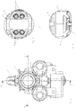
- the multi-nozzle body according to Fig. 1 to 10 has the housing 1 on. On the housing, the fastening means 2 is arranged, with which the multi-nozzle body can be attached to frame members, distribution linkage, etc.
- the liquid line to which the multi-nozzle body is connected is the respective multi-nozzle body supply.
- the liquid line 3 is connected to the branch line 5 arranged in the housing 1 in a branch region 4.
- the branch line 5 opens into the distribution chamber 6 arranged in the housing 1.
- the connecting lines 7 are shut off in the region of the distributor space 6 by means of shut-off valves 11 having shut-off elements 10. About this shut-off elements 10, the connecting lines 7 with the supply line 5 are selectively connectable and / or against her shut off.
- the shut-off elements 10 can be actuated via switchable actuating elements 12 and thus brought into the respective shut-off or flow-through position.
- the shut-off valves 11 each have a valve seat 13 arranged in the housing 1, to each of which a ring section designed as a sealing ring 14 is assigned.
- the shut-off elements 10 are spherical, formed in the embodiment as balls. If the valve balls 10 are located in the valve seat 13, they cooperate sealingly in this shut-off position with the sealing ring 14 of the valve seat 13.
- the balls 10 are associated with compression springs 15, by means of which they are pressed in the direction of the valve seat 13.
- an intermediate piece 16 is arranged, in particular the FIGS. 12 and 13 can be seen.
- the voltage applied to the valve ball 10 surface 17 of the intermediate piece 16 is recessed in the inner region 18 opposite to the outer peripheral portion 19 is formed as the Fig. 13 is particularly easy to remove.
- the voltage applied to the ball 10 surface 17 of the intermediate piece 16, the valve ball 10 at least partially encompassing and / or form-fitting on and detected formed.
- the surface 17 of the intermediate piece 16 resting against the valve ball 10 is concave.
- the voltage applied to the valve ball 10 surface 17 of the intermediate piece 16 has a configuration similar to a ball portion and the radius of the voltage applied to the valve ball 10 concave surface 17 of the intermediate piece 16 is at least 1.5 times, preferably 2 to 5 times larger as the radius of the valve balls 16.
- the switchable actuator 12 is disc-like and rotatably connected to a mounted in the housing 1 shift shaft 20.
- the actuator 12 has a plurality of switching cams 21, 22, as the FIGS. 9 and 10 point to.
- the actuating element 12 has two switching cams 21, 22.
- the switching shaft 20 of the actuating element 12 is rotatably connected to a motor control element 23 which is designed as an electric motor and thus rotatable about the motor actuator about its axis of rotation.
- One of the two switching cams 21 is configured such that it can only press a valve element designed as a ball 10 out of the valve seat 13, so that the flow to a connecting line 7 is released.
- the other of the two switching cams 22 is configured such that it can simultaneously move two shut-off elements configured as balls 10 into a position releasing the flow into the respective connecting lines 7, that is to say that it simultaneously removes two valve elements formed as balls 10 from their valve seats 13 can press.
- the actuator 12 with the two switching cams 21, 22 is rotatable in different positions, as for some possible positions in the FIGS. 9 and 10 is shown. As can be seen, depending on the switching position of the actuating element 12, the flow is released for no, one or more connecting lines 7 to the Ausbringdüsen leading discharge lines 8. Thus, optionally, none, one or more connecting lines 7 and thus Ausbringdüsen be supplied in different combinations, the liquid to be delivered.
- the switching cams 21, 22 of the disc-like actuating element 12 act with an approximately perpendicular to the axis of rotation 24 of the actuating element 12 approximately at the level of the center of the balls 10 of the check valves 9 on the balls 10 and press in this in the direction of rotation 24 perpendicular direction via the formed as sealing rings 15 annular portions of the respective valve seat 13 from the valve seat 13 in a flow to the respective connecting line 7 releasing position.
- the respective motor adjusting element 23, which is designed as an electric motor, is connected via connecting lines, not shown, to a power supply and a control device, which may be designed, for example, as an on-board computer.
Landscapes
- Engineering & Computer Science (AREA)
- General Engineering & Computer Science (AREA)
- Mechanical Engineering (AREA)
- Taps Or Cocks (AREA)
Claims (2)
- Tête de buse multiple avec plusieurs buses de sortie à agencer sur la conduite de liquide (3) d'un pulvérisateur agricole, dans laquelle la conduite de liquide (3) peut être raccordée à la conduite d'alimentation de la tête de buse multiple, dans laquelle la conduite d'alimentation débouche dans une chambre de distributeur (6), dans laquelle plusieurs conduites de liaison (7) conduisant respectivement à une buse de sortie partent de la chambre de distributeur (6), dans laquelle un élément d'arrêt formé par une vanne d'arrêt associée respectivement à une conduite de liaison (7) est associée dans la chambre de distributeur (6), dans laquelle une ou plusieurs conduite(s) de liaison (7) peut/peuvent être au choix raccordée(s) à la conduite d'alimentation et/ou fermée(s) par rapport à celle-ci au moyen des éléments d'arrêt (10) des vannes d'arrêt (11) actionnable par un élément d'actionnement commutable, dans laquelle l'élément d'actionnement (12) présente plusieurs cames de commutation et peut tourner autour d'un axe de rotation dans différentes positions de commutation, dans laquelle les éléments d'arrêt (10) sont de forme sphérique et sont disposés dans leur position d'arrêt de façon étanche dans un siège de vanne présentant une partie annulaire, dans laquelle les éléments d'arrêt sphériques (10) sont déplaçables dans une direction au moins approximativement perpendiculaire à l'axe de rotation de l'élément d'actionnement (12) sur les parois inclinées de la partie annulaire du siège de vanne à partir du siège de vanne jusqu'à une position libérant le débit vers la conduite de liaison respective (7), dans laquelle les éléments de vanne sphériques (10) sont réalisés sous forme de billes et peuvent être pressés en position d'étanchéité dans leur siège de vanne au moyen de ressorts de pression (15), caractérisée en ce qu'une pièce intermédiaire (16) est disposée entre le ressort de pression (15) respectif et la sphère (10) respective, en ce que la surface (17) de la pièce intermédiaire (16) qui repose contre la sphère de vanne (10), dans la zone intérieure (18) est réalisée évidée de manière concave par rapport à la zone circonférentielle (19) extérieure et en ce que la surface (17) de la pièce intermédiaire (16) qui repose contre la sphère de vanne (10) possède une configuration similaire à une portion de sphère et le rayon de la surface (17) concave de la pièce intermédiaire (16) qui repose contre la sphère de vanne (10) est au moins 1,5 fois, de préférence de 2 à 5 fois plus grand que le rayon des sphères de vanne (10).
- Tête de buse multiple selon la revendication 1, caractérisée en ce que la surface (17) de la pièce intermédiaire (16) qui repose contre la sphère (10) est configurée pour envelopper et/ou enchâsser et saisir par complémentarité de formes au moins partiellement la sphère de vanne (10).
Applications Claiming Priority (1)
| Application Number | Priority Date | Filing Date | Title |
|---|---|---|---|
| DE201310104674 DE102013104674A1 (de) | 2013-05-07 | 2013-05-07 | Mehrfachdüsenkörper |
Publications (2)
| Publication Number | Publication Date |
|---|---|
| EP2801410A1 EP2801410A1 (fr) | 2014-11-12 |
| EP2801410B1 true EP2801410B1 (fr) | 2018-10-10 |
Family
ID=50846895
Family Applications (1)
| Application Number | Title | Priority Date | Filing Date |
|---|---|---|---|
| EP14401051.9A Active EP2801410B1 (fr) | 2013-05-07 | 2014-05-05 | Corps à buses multiples |
Country Status (2)
| Country | Link |
|---|---|
| EP (1) | EP2801410B1 (fr) |
| DE (1) | DE102013104674A1 (fr) |
Cited By (1)
| Publication number | Priority date | Publication date | Assignee | Title |
|---|---|---|---|---|
| FR3143268A1 (fr) * | 2022-12-19 | 2024-06-21 | Exel Industries | Porte-buses multiple pour un système de pulvérisation agricole |
Family Cites Families (4)
| Publication number | Priority date | Publication date | Assignee | Title |
|---|---|---|---|---|
| US4570663A (en) * | 1983-04-22 | 1986-02-18 | Shasta Industries, Inc. | Distribution valve with dual cams to prevent uncontrolled excursions of valve balls |
| US5407173A (en) * | 1994-03-02 | 1995-04-18 | The Lincoln Electric Company | Valve for gas burning torch |
| JP2003232455A (ja) * | 2002-02-12 | 2003-08-22 | Sankyo Seiki Mfg Co Ltd | バルブ駆動装置 |
| DE102010036437A1 (de) | 2010-07-16 | 2012-01-19 | Amazonen-Werke H. Dreyer Gmbh & Co. Kg | Mehrfachdüsenkörper |
-
2013
- 2013-05-07 DE DE201310104674 patent/DE102013104674A1/de not_active Withdrawn
-
2014
- 2014-05-05 EP EP14401051.9A patent/EP2801410B1/fr active Active
Non-Patent Citations (1)
| Title |
|---|
| None * |
Cited By (3)
| Publication number | Priority date | Publication date | Assignee | Title |
|---|---|---|---|---|
| FR3143268A1 (fr) * | 2022-12-19 | 2024-06-21 | Exel Industries | Porte-buses multiple pour un système de pulvérisation agricole |
| EP4388872A1 (fr) | 2022-12-19 | 2024-06-26 | Exel Industries | Porte-buses multiple pour un système de pulvérisation agricole |
| AU2023278025B2 (en) * | 2022-12-19 | 2026-02-05 | Exel Industries | Multiple nozzle holder for agricultural spray system |
Also Published As
| Publication number | Publication date |
|---|---|
| EP2801410A1 (fr) | 2014-11-12 |
| DE102013104674A1 (de) | 2014-11-27 |
Similar Documents
| Publication | Publication Date | Title |
|---|---|---|
| EP2593235B1 (fr) | Tête de buse multiple avec vanne multivoies | |
| DE102007019064B3 (de) | Drehschieber | |
| WO2002087779A1 (fr) | Dispositif de pulverisation pour pulveriser des liquides, notamment a des fins agricoles | |
| EP2529136B1 (fr) | Robinet d'arrêt pour le domaine des installations de second oeuvre | |
| EP2710940B1 (fr) | Soupape à plusieurs voies | |
| EP2801410B1 (fr) | Corps à buses multiples | |
| EP1821017A2 (fr) | Soupape à plusieurs voies | |
| DE19847039C1 (de) | Absperrarmatur | |
| EP0423634B1 (fr) | Vanne d'arrêt et de régulation | |
| EP3369972A1 (fr) | Soupape à disque | |
| DE102004060517B3 (de) | Absperrorgan aus Kunststoff für Fluidleitungen | |
| DE102009008493A1 (de) | Düsenkörper | |
| DE10232506A1 (de) | Zapfhahn für Getränke mit einem Drehschieber | |
| DE102013218014B4 (de) | Gasventileinrichtung und Gasgerät mit einer Gasventileinrichtung | |
| DE102008009884C5 (de) | Düsenkörper | |
| EP2801408B1 (fr) | Conduite de liquide dotée d'un corps de tuyère associé | |
| EP2801411A1 (fr) | Corps à buses multiples | |
| DE1153955B (de) | Rueckschlagventil fuer Rohrleitungen | |
| EP2801409A1 (fr) | Conduite de liquide dotée d'un corps de tuyère associé | |
| EP1821013A2 (fr) | Soupape à plusieurs voies | |
| EP2336616A1 (fr) | Robinet à voies multiples | |
| DE3203859C2 (fr) | ||
| DE489107C (de) | Verstellvorrichtung fuer drehbar gelagerte Koerper, insbesondere fuer drehbare Scheinwerfer von Kraftfahrzeugen | |
| DE2924372C3 (de) | Ventil, insbesondere thermostatisch gesteuertes Heizkörperventil mit Voreinstellung | |
| CH356971A (de) | Absperrventil |
Legal Events
| Date | Code | Title | Description |
|---|---|---|---|
| PUAI | Public reference made under article 153(3) epc to a published international application that has entered the european phase |
Free format text: ORIGINAL CODE: 0009012 |
|
| 17P | Request for examination filed |
Effective date: 20140505 |
|
| AK | Designated contracting states |
Kind code of ref document: A1 Designated state(s): AL AT BE BG CH CY CZ DE DK EE ES FI FR GB GR HR HU IE IS IT LI LT LU LV MC MK MT NL NO PL PT RO RS SE SI SK SM TR |
|
| AX | Request for extension of the european patent |
Extension state: BA ME |
|
| R17P | Request for examination filed (corrected) |
Effective date: 20150508 |
|
| RBV | Designated contracting states (corrected) |
Designated state(s): AL AT BE BG CH CY CZ DE DK EE ES FI FR GB GR HR HU IE IS IT LI LT LU LV MC MK MT NL NO PL PT RO RS SE SI SK SM TR |
|
| GRAP | Despatch of communication of intention to grant a patent |
Free format text: ORIGINAL CODE: EPIDOSNIGR1 |
|
| STAA | Information on the status of an ep patent application or granted ep patent |
Free format text: STATUS: GRANT OF PATENT IS INTENDED |
|
| RIC1 | Information provided on ipc code assigned before grant |
Ipc: B05B 1/16 20060101AFI20180530BHEP Ipc: F16K 11/16 20060101ALI20180530BHEP Ipc: B05B 1/20 20060101ALN20180530BHEP Ipc: F16K 31/524 20060101ALI20180530BHEP Ipc: B05B 1/30 20060101ALI20180530BHEP |
|
| INTG | Intention to grant announced |
Effective date: 20180629 |
|
| GRAS | Grant fee paid |
Free format text: ORIGINAL CODE: EPIDOSNIGR3 |
|
| GRAA | (expected) grant |
Free format text: ORIGINAL CODE: 0009210 |
|
| STAA | Information on the status of an ep patent application or granted ep patent |
Free format text: STATUS: THE PATENT HAS BEEN GRANTED |
|
| AK | Designated contracting states |
Kind code of ref document: B1 Designated state(s): AL AT BE BG CH CY CZ DE DK EE ES FI FR GB GR HR HU IE IS IT LI LT LU LV MC MK MT NL NO PL PT RO RS SE SI SK SM TR |
|
| REG | Reference to a national code |
Ref country code: GB Ref legal event code: FG4D Free format text: NOT ENGLISH |
|
| REG | Reference to a national code |
Ref country code: CH Ref legal event code: EP Ref country code: AT Ref legal event code: REF Ref document number: 1050615 Country of ref document: AT Kind code of ref document: T Effective date: 20181015 |
|
| REG | Reference to a national code |
Ref country code: IE Ref legal event code: FG4D Free format text: LANGUAGE OF EP DOCUMENT: GERMAN Ref country code: DE Ref legal event code: R096 Ref document number: 502014009697 Country of ref document: DE |
|
| REG | Reference to a national code |
Ref country code: NL Ref legal event code: FP |
|
| REG | Reference to a national code |
Ref country code: LT Ref legal event code: MG4D |
|
| PG25 | Lapsed in a contracting state [announced via postgrant information from national office to epo] |
Ref country code: FI Free format text: LAPSE BECAUSE OF FAILURE TO SUBMIT A TRANSLATION OF THE DESCRIPTION OR TO PAY THE FEE WITHIN THE PRESCRIBED TIME-LIMIT Effective date: 20181010 Ref country code: NO Free format text: LAPSE BECAUSE OF FAILURE TO SUBMIT A TRANSLATION OF THE DESCRIPTION OR TO PAY THE FEE WITHIN THE PRESCRIBED TIME-LIMIT Effective date: 20190110 Ref country code: IS Free format text: LAPSE BECAUSE OF FAILURE TO SUBMIT A TRANSLATION OF THE DESCRIPTION OR TO PAY THE FEE WITHIN THE PRESCRIBED TIME-LIMIT Effective date: 20190210 Ref country code: HR Free format text: LAPSE BECAUSE OF FAILURE TO SUBMIT A TRANSLATION OF THE DESCRIPTION OR TO PAY THE FEE WITHIN THE PRESCRIBED TIME-LIMIT Effective date: 20181010 Ref country code: LT Free format text: LAPSE BECAUSE OF FAILURE TO SUBMIT A TRANSLATION OF THE DESCRIPTION OR TO PAY THE FEE WITHIN THE PRESCRIBED TIME-LIMIT Effective date: 20181010 Ref country code: BG Free format text: LAPSE BECAUSE OF FAILURE TO SUBMIT A TRANSLATION OF THE DESCRIPTION OR TO PAY THE FEE WITHIN THE PRESCRIBED TIME-LIMIT Effective date: 20190110 Ref country code: PL Free format text: LAPSE BECAUSE OF FAILURE TO SUBMIT A TRANSLATION OF THE DESCRIPTION OR TO PAY THE FEE WITHIN THE PRESCRIBED TIME-LIMIT Effective date: 20181010 Ref country code: ES Free format text: LAPSE BECAUSE OF FAILURE TO SUBMIT A TRANSLATION OF THE DESCRIPTION OR TO PAY THE FEE WITHIN THE PRESCRIBED TIME-LIMIT Effective date: 20181010 Ref country code: LV Free format text: LAPSE BECAUSE OF FAILURE TO SUBMIT A TRANSLATION OF THE DESCRIPTION OR TO PAY THE FEE WITHIN THE PRESCRIBED TIME-LIMIT Effective date: 20181010 |
|
| PG25 | Lapsed in a contracting state [announced via postgrant information from national office to epo] |
Ref country code: PT Free format text: LAPSE BECAUSE OF FAILURE TO SUBMIT A TRANSLATION OF THE DESCRIPTION OR TO PAY THE FEE WITHIN THE PRESCRIBED TIME-LIMIT Effective date: 20190210 Ref country code: AL Free format text: LAPSE BECAUSE OF FAILURE TO SUBMIT A TRANSLATION OF THE DESCRIPTION OR TO PAY THE FEE WITHIN THE PRESCRIBED TIME-LIMIT Effective date: 20181010 Ref country code: RS Free format text: LAPSE BECAUSE OF FAILURE TO SUBMIT A TRANSLATION OF THE DESCRIPTION OR TO PAY THE FEE WITHIN THE PRESCRIBED TIME-LIMIT Effective date: 20181010 Ref country code: GR Free format text: LAPSE BECAUSE OF FAILURE TO SUBMIT A TRANSLATION OF THE DESCRIPTION OR TO PAY THE FEE WITHIN THE PRESCRIBED TIME-LIMIT Effective date: 20190111 Ref country code: SE Free format text: LAPSE BECAUSE OF FAILURE TO SUBMIT A TRANSLATION OF THE DESCRIPTION OR TO PAY THE FEE WITHIN THE PRESCRIBED TIME-LIMIT Effective date: 20181010 |
|
| REG | Reference to a national code |
Ref country code: DE Ref legal event code: R097 Ref document number: 502014009697 Country of ref document: DE |
|
| PG25 | Lapsed in a contracting state [announced via postgrant information from national office to epo] |
Ref country code: DK Free format text: LAPSE BECAUSE OF FAILURE TO SUBMIT A TRANSLATION OF THE DESCRIPTION OR TO PAY THE FEE WITHIN THE PRESCRIBED TIME-LIMIT Effective date: 20181010 Ref country code: CZ Free format text: LAPSE BECAUSE OF FAILURE TO SUBMIT A TRANSLATION OF THE DESCRIPTION OR TO PAY THE FEE WITHIN THE PRESCRIBED TIME-LIMIT Effective date: 20181010 |
|
| PLBE | No opposition filed within time limit |
Free format text: ORIGINAL CODE: 0009261 |
|
| STAA | Information on the status of an ep patent application or granted ep patent |
Free format text: STATUS: NO OPPOSITION FILED WITHIN TIME LIMIT |
|
| PG25 | Lapsed in a contracting state [announced via postgrant information from national office to epo] |
Ref country code: SK Free format text: LAPSE BECAUSE OF FAILURE TO SUBMIT A TRANSLATION OF THE DESCRIPTION OR TO PAY THE FEE WITHIN THE PRESCRIBED TIME-LIMIT Effective date: 20181010 Ref country code: RO Free format text: LAPSE BECAUSE OF FAILURE TO SUBMIT A TRANSLATION OF THE DESCRIPTION OR TO PAY THE FEE WITHIN THE PRESCRIBED TIME-LIMIT Effective date: 20181010 Ref country code: EE Free format text: LAPSE BECAUSE OF FAILURE TO SUBMIT A TRANSLATION OF THE DESCRIPTION OR TO PAY THE FEE WITHIN THE PRESCRIBED TIME-LIMIT Effective date: 20181010 Ref country code: SM Free format text: LAPSE BECAUSE OF FAILURE TO SUBMIT A TRANSLATION OF THE DESCRIPTION OR TO PAY THE FEE WITHIN THE PRESCRIBED TIME-LIMIT Effective date: 20181010 |
|
| 26N | No opposition filed |
Effective date: 20190711 |
|
| PG25 | Lapsed in a contracting state [announced via postgrant information from national office to epo] |
Ref country code: SI Free format text: LAPSE BECAUSE OF FAILURE TO SUBMIT A TRANSLATION OF THE DESCRIPTION OR TO PAY THE FEE WITHIN THE PRESCRIBED TIME-LIMIT Effective date: 20181010 |
|
| REG | Reference to a national code |
Ref country code: CH Ref legal event code: PL |
|
| GBPC | Gb: european patent ceased through non-payment of renewal fee |
Effective date: 20190505 |
|
| PG25 | Lapsed in a contracting state [announced via postgrant information from national office to epo] |
Ref country code: MC Free format text: LAPSE BECAUSE OF FAILURE TO SUBMIT A TRANSLATION OF THE DESCRIPTION OR TO PAY THE FEE WITHIN THE PRESCRIBED TIME-LIMIT Effective date: 20181010 Ref country code: CH Free format text: LAPSE BECAUSE OF NON-PAYMENT OF DUE FEES Effective date: 20190531 Ref country code: LI Free format text: LAPSE BECAUSE OF NON-PAYMENT OF DUE FEES Effective date: 20190531 |
|
| REG | Reference to a national code |
Ref country code: BE Ref legal event code: MM Effective date: 20190531 |
|
| PG25 | Lapsed in a contracting state [announced via postgrant information from national office to epo] |
Ref country code: LU Free format text: LAPSE BECAUSE OF NON-PAYMENT OF DUE FEES Effective date: 20190505 |
|
| PG25 | Lapsed in a contracting state [announced via postgrant information from national office to epo] |
Ref country code: TR Free format text: LAPSE BECAUSE OF FAILURE TO SUBMIT A TRANSLATION OF THE DESCRIPTION OR TO PAY THE FEE WITHIN THE PRESCRIBED TIME-LIMIT Effective date: 20181010 |
|
| PG25 | Lapsed in a contracting state [announced via postgrant information from national office to epo] |
Ref country code: GB Free format text: LAPSE BECAUSE OF NON-PAYMENT OF DUE FEES Effective date: 20190505 Ref country code: IE Free format text: LAPSE BECAUSE OF NON-PAYMENT OF DUE FEES Effective date: 20190505 |
|
| PG25 | Lapsed in a contracting state [announced via postgrant information from national office to epo] |
Ref country code: BE Free format text: LAPSE BECAUSE OF NON-PAYMENT OF DUE FEES Effective date: 20190531 |
|
| REG | Reference to a national code |
Ref country code: AT Ref legal event code: MM01 Ref document number: 1050615 Country of ref document: AT Kind code of ref document: T Effective date: 20190505 |
|
| PG25 | Lapsed in a contracting state [announced via postgrant information from national office to epo] |
Ref country code: AT Free format text: LAPSE BECAUSE OF NON-PAYMENT OF DUE FEES Effective date: 20190505 |
|
| REG | Reference to a national code |
Ref country code: DE Ref legal event code: R081 Ref document number: 502014009697 Country of ref document: DE Owner name: AMAZONEN-WERKE H. DREYER SE & CO. KG, DE Free format text: FORMER OWNER: AMAZONEN-WERKE H. DREYER GMBH & CO. KG, 49205 HASBERGEN, DE |
|
| PG25 | Lapsed in a contracting state [announced via postgrant information from national office to epo] |
Ref country code: CY Free format text: LAPSE BECAUSE OF FAILURE TO SUBMIT A TRANSLATION OF THE DESCRIPTION OR TO PAY THE FEE WITHIN THE PRESCRIBED TIME-LIMIT Effective date: 20181010 |
|
| PG25 | Lapsed in a contracting state [announced via postgrant information from national office to epo] |
Ref country code: MT Free format text: LAPSE BECAUSE OF FAILURE TO SUBMIT A TRANSLATION OF THE DESCRIPTION OR TO PAY THE FEE WITHIN THE PRESCRIBED TIME-LIMIT Effective date: 20181010 Ref country code: HU Free format text: LAPSE BECAUSE OF FAILURE TO SUBMIT A TRANSLATION OF THE DESCRIPTION OR TO PAY THE FEE WITHIN THE PRESCRIBED TIME-LIMIT; INVALID AB INITIO Effective date: 20140505 |
|
| PG25 | Lapsed in a contracting state [announced via postgrant information from national office to epo] |
Ref country code: MK Free format text: LAPSE BECAUSE OF FAILURE TO SUBMIT A TRANSLATION OF THE DESCRIPTION OR TO PAY THE FEE WITHIN THE PRESCRIBED TIME-LIMIT Effective date: 20181010 |
|
| P01 | Opt-out of the competence of the unified patent court (upc) registered |
Effective date: 20230524 |
|
| PGFP | Annual fee paid to national office [announced via postgrant information from national office to epo] |
Ref country code: NL Payment date: 20250317 Year of fee payment: 12 |
|
| PGFP | Annual fee paid to national office [announced via postgrant information from national office to epo] |
Ref country code: FR Payment date: 20250310 Year of fee payment: 12 |
|
| PGFP | Annual fee paid to national office [announced via postgrant information from national office to epo] |
Ref country code: DE Payment date: 20250311 Year of fee payment: 12 |
|
| PGFP | Annual fee paid to national office [announced via postgrant information from national office to epo] |
Ref country code: IT Payment date: 20250422 Year of fee payment: 12 |