EP2799958A1 - Kopfmontierte anzeige und informationsanzeigevorrichtung - Google Patents
Kopfmontierte anzeige und informationsanzeigevorrichtung Download PDFInfo
- Publication number
- EP2799958A1 EP2799958A1 EP12862497.0A EP12862497A EP2799958A1 EP 2799958 A1 EP2799958 A1 EP 2799958A1 EP 12862497 A EP12862497 A EP 12862497A EP 2799958 A1 EP2799958 A1 EP 2799958A1
- Authority
- EP
- European Patent Office
- Prior art keywords
- image
- display
- operation surface
- detection target
- input operation
- Prior art date
- Legal status (The legal status is an assumption and is not a legal conclusion. Google has not performed a legal analysis and makes no representation as to the accuracy of the status listed.)
- Withdrawn
Links
- 238000001514 detection method Methods 0.000 claims abstract description 101
- 238000005516 engineering process Methods 0.000 abstract description 34
- 238000010586 diagram Methods 0.000 description 23
- 230000005540 biological transmission Effects 0.000 description 21
- 230000008859 change Effects 0.000 description 16
- 238000004891 communication Methods 0.000 description 11
- 230000006870 function Effects 0.000 description 8
- 230000007274 generation of a signal involved in cell-cell signaling Effects 0.000 description 7
- 238000000034 method Methods 0.000 description 6
- 239000000463 material Substances 0.000 description 5
- 230000003287 optical effect Effects 0.000 description 5
- 230000009467 reduction Effects 0.000 description 5
- 239000004065 semiconductor Substances 0.000 description 4
- 210000003128 head Anatomy 0.000 description 3
- 230000010365 information processing Effects 0.000 description 3
- 230000007774 longterm Effects 0.000 description 3
- 239000003086 colorant Substances 0.000 description 2
- 230000000694 effects Effects 0.000 description 2
- 238000003384 imaging method Methods 0.000 description 2
- 239000004973 liquid crystal related substance Substances 0.000 description 2
- 229920003023 plastic Polymers 0.000 description 2
- 239000005020 polyethylene terephthalate Substances 0.000 description 2
- 229920000139 polyethylene terephthalate Polymers 0.000 description 2
- 239000000758 substrate Substances 0.000 description 2
- 238000010897 surface acoustic wave method Methods 0.000 description 2
- 210000000707 wrist Anatomy 0.000 description 2
- 229920000178 Acrylic resin Polymers 0.000 description 1
- 239000004925 Acrylic resin Substances 0.000 description 1
- 239000000956 alloy Substances 0.000 description 1
- 229910045601 alloy Inorganic materials 0.000 description 1
- 239000000919 ceramic Substances 0.000 description 1
- 210000005069 ears Anatomy 0.000 description 1
- 230000005489 elastic deformation Effects 0.000 description 1
- 239000011521 glass Substances 0.000 description 1
- 208000013057 hereditary mucoepithelial dysplasia Diseases 0.000 description 1
- 239000011159 matrix material Substances 0.000 description 1
- 239000002184 metal Substances 0.000 description 1
- 238000012986 modification Methods 0.000 description 1
- 230000004048 modification Effects 0.000 description 1
- 239000004033 plastic Substances 0.000 description 1
- 229920005668 polycarbonate resin Polymers 0.000 description 1
- 239000004431 polycarbonate resin Substances 0.000 description 1
- -1 polyethylene terephthalate Polymers 0.000 description 1
- 230000008569 process Effects 0.000 description 1
- 230000005236 sound signal Effects 0.000 description 1
- 229920003002 synthetic resin Polymers 0.000 description 1
- 239000000057 synthetic resin Substances 0.000 description 1
- 238000002834 transmittance Methods 0.000 description 1
Images


Classifications
-
- G—PHYSICS
- G09—EDUCATION; CRYPTOGRAPHY; DISPLAY; ADVERTISING; SEALS
- G09G—ARRANGEMENTS OR CIRCUITS FOR CONTROL OF INDICATING DEVICES USING STATIC MEANS TO PRESENT VARIABLE INFORMATION
- G09G5/00—Control arrangements or circuits for visual indicators common to cathode-ray tube indicators and other visual indicators
- G09G5/36—Control arrangements or circuits for visual indicators common to cathode-ray tube indicators and other visual indicators characterised by the display of a graphic pattern, e.g. using an all-points-addressable [APA] memory
- G09G5/37—Details of the operation on graphic patterns
- G09G5/377—Details of the operation on graphic patterns for mixing or overlaying two or more graphic patterns
-
- G—PHYSICS
- G06—COMPUTING; CALCULATING OR COUNTING
- G06F—ELECTRIC DIGITAL DATA PROCESSING
- G06F3/00—Input arrangements for transferring data to be processed into a form capable of being handled by the computer; Output arrangements for transferring data from processing unit to output unit, e.g. interface arrangements
- G06F3/01—Input arrangements or combined input and output arrangements for interaction between user and computer
- G06F3/048—Interaction techniques based on graphical user interfaces [GUI]
- G06F3/0487—Interaction techniques based on graphical user interfaces [GUI] using specific features provided by the input device, e.g. functions controlled by the rotation of a mouse with dual sensing arrangements, or of the nature of the input device, e.g. tap gestures based on pressure sensed by a digitiser
- G06F3/0488—Interaction techniques based on graphical user interfaces [GUI] using specific features provided by the input device, e.g. functions controlled by the rotation of a mouse with dual sensing arrangements, or of the nature of the input device, e.g. tap gestures based on pressure sensed by a digitiser using a touch-screen or digitiser, e.g. input of commands through traced gestures
-
- G—PHYSICS
- G02—OPTICS
- G02B—OPTICAL ELEMENTS, SYSTEMS OR APPARATUS
- G02B27/00—Optical systems or apparatus not provided for by any of the groups G02B1/00 - G02B26/00, G02B30/00
- G02B27/01—Head-up displays
- G02B27/017—Head mounted
-
- G—PHYSICS
- G06—COMPUTING; CALCULATING OR COUNTING
- G06F—ELECTRIC DIGITAL DATA PROCESSING
- G06F3/00—Input arrangements for transferring data to be processed into a form capable of being handled by the computer; Output arrangements for transferring data from processing unit to output unit, e.g. interface arrangements
- G06F3/01—Input arrangements or combined input and output arrangements for interaction between user and computer
- G06F3/011—Arrangements for interaction with the human body, e.g. for user immersion in virtual reality
-
- G—PHYSICS
- G06—COMPUTING; CALCULATING OR COUNTING
- G06F—ELECTRIC DIGITAL DATA PROCESSING
- G06F3/00—Input arrangements for transferring data to be processed into a form capable of being handled by the computer; Output arrangements for transferring data from processing unit to output unit, e.g. interface arrangements
- G06F3/01—Input arrangements or combined input and output arrangements for interaction between user and computer
- G06F3/03—Arrangements for converting the position or the displacement of a member into a coded form
- G06F3/041—Digitisers, e.g. for touch screens or touch pads, characterised by the transducing means
- G06F3/0416—Control or interface arrangements specially adapted for digitisers
-
- G—PHYSICS
- G06—COMPUTING; CALCULATING OR COUNTING
- G06F—ELECTRIC DIGITAL DATA PROCESSING
- G06F3/00—Input arrangements for transferring data to be processed into a form capable of being handled by the computer; Output arrangements for transferring data from processing unit to output unit, e.g. interface arrangements
- G06F3/01—Input arrangements or combined input and output arrangements for interaction between user and computer
- G06F3/048—Interaction techniques based on graphical user interfaces [GUI]
- G06F3/0484—Interaction techniques based on graphical user interfaces [GUI] for the control of specific functions or operations, e.g. selecting or manipulating an object, an image or a displayed text element, setting a parameter value or selecting a range
- G06F3/0485—Scrolling or panning
-
- G—PHYSICS
- G02—OPTICS
- G02B—OPTICAL ELEMENTS, SYSTEMS OR APPARATUS
- G02B27/00—Optical systems or apparatus not provided for by any of the groups G02B1/00 - G02B26/00, G02B30/00
- G02B27/01—Head-up displays
- G02B27/0101—Head-up displays characterised by optical features
- G02B2027/014—Head-up displays characterised by optical features comprising information/image processing systems
-
- G—PHYSICS
- G02—OPTICS
- G02B—OPTICAL ELEMENTS, SYSTEMS OR APPARATUS
- G02B27/00—Optical systems or apparatus not provided for by any of the groups G02B1/00 - G02B26/00, G02B30/00
- G02B27/01—Head-up displays
- G02B27/017—Head mounted
- G02B2027/0178—Eyeglass type
-
- G—PHYSICS
- G02—OPTICS
- G02B—OPTICAL ELEMENTS, SYSTEMS OR APPARATUS
- G02B27/00—Optical systems or apparatus not provided for by any of the groups G02B1/00 - G02B26/00, G02B30/00
- G02B27/01—Head-up displays
- G02B27/0179—Display position adjusting means not related to the information to be displayed
- G02B2027/0187—Display position adjusting means not related to the information to be displayed slaved to motion of at least a part of the body of the user, e.g. head, eye
-
- G—PHYSICS
- G06—COMPUTING; CALCULATING OR COUNTING
- G06F—ELECTRIC DIGITAL DATA PROCESSING
- G06F2203/00—Indexing scheme relating to G06F3/00 - G06F3/048
- G06F2203/041—Indexing scheme relating to G06F3/041 - G06F3/045
- G06F2203/04101—2.5D-digitiser, i.e. digitiser detecting the X/Y position of the input means, finger or stylus, also when it does not touch, but is proximate to the digitiser's interaction surface and also measures the distance of the input means within a short range in the Z direction, possibly with a separate measurement setup
-
- G—PHYSICS
- G06—COMPUTING; CALCULATING OR COUNTING
- G06F—ELECTRIC DIGITAL DATA PROCESSING
- G06F2203/00—Indexing scheme relating to G06F3/00 - G06F3/048
- G06F2203/048—Indexing scheme relating to G06F3/048
- G06F2203/04801—Cursor retrieval aid, i.e. visual aspect modification, blinking, colour changes, enlargement or other visual cues, for helping user do find the cursor in graphical user interfaces
-
- G—PHYSICS
- G06—COMPUTING; CALCULATING OR COUNTING
- G06F—ELECTRIC DIGITAL DATA PROCESSING
- G06F2203/00—Indexing scheme relating to G06F3/00 - G06F3/048
- G06F2203/048—Indexing scheme relating to G06F3/048
- G06F2203/04806—Zoom, i.e. interaction techniques or interactors for controlling the zooming operation
-
- G—PHYSICS
- G06—COMPUTING; CALCULATING OR COUNTING
- G06F—ELECTRIC DIGITAL DATA PROCESSING
- G06F2203/00—Indexing scheme relating to G06F3/00 - G06F3/048
- G06F2203/048—Indexing scheme relating to G06F3/048
- G06F2203/04808—Several contacts: gestures triggering a specific function, e.g. scrolling, zooming, right-click, when the user establishes several contacts with the surface simultaneously; e.g. using several fingers or a combination of fingers and pen
-
- G—PHYSICS
- G09—EDUCATION; CRYPTOGRAPHY; DISPLAY; ADVERTISING; SEALS
- G09G—ARRANGEMENTS OR CIRCUITS FOR CONTROL OF INDICATING DEVICES USING STATIC MEANS TO PRESENT VARIABLE INFORMATION
- G09G3/00—Control arrangements or circuits, of interest only in connection with visual indicators other than cathode-ray tubes
- G09G3/001—Control arrangements or circuits, of interest only in connection with visual indicators other than cathode-ray tubes using specific devices not provided for in groups G09G3/02 - G09G3/36, e.g. using an intermediate record carrier such as a film slide; Projection systems; Display of non-alphanumerical information, solely or in combination with alphanumerical information, e.g. digital display on projected diapositive as background
- G09G3/003—Control arrangements or circuits, of interest only in connection with visual indicators other than cathode-ray tubes using specific devices not provided for in groups G09G3/02 - G09G3/36, e.g. using an intermediate record carrier such as a film slide; Projection systems; Display of non-alphanumerical information, solely or in combination with alphanumerical information, e.g. digital display on projected diapositive as background to produce spatial visual effects
Definitions
- the present technology relates to a head-mounted display and an information display apparatus.
- HMD head-mounted display
- the HMDs are classified into a non-see-through HMD that does not allow external light to pass therethrough and displays only a predetermined image to the user and into a see-through HMD that allows the user to view an outside world and displays, for example, a predetermined image overlapping with a field of view of the user.
- Patent Document 1 describes a non-see-through HMD including a main body provided with an operation input unit such as a button.
- Patent Document 2 describes a see-through HMD with an input operation surface of a touch panel being placed in a field-of-view area of the user for performing an input operation.
- a head-mounted display includes a reception unit, an image display element, and a display processing unit.
- the reception unit receives an operation signal including information on a relative position of a detection target in contact with an input operation surface, which is output from an input device.
- the image display element forms an image presented to a user.
- the display processing unit causes, based on the operation signal, the image display element to display an operation image with an auxiliary image indicating a position of the detection target being overlapped on the image.
- the user By wearing the head-mounted display (HMD), the user can view the information on the relative position of the detection target such as a finger in contact with the input operation surface as the auxiliary image in the operation image presented by the HMD. This enables the user to perform an intuitive operation while viewing the operation image by the HMD without needing to check the input operation surface.
- the detection target such as a finger in contact with the input operation surface as the auxiliary image in the operation image presented by the HMD.
- the reception unit may further receive an image signal output from the input device, and the display processing unit may cause, based on the image signal, the image display element to display the image.
- the HMD having such a configuration can use not only a dedicated input device but also, for example, a portable terminal or the like installing a touch panel as the input device. This makes it possible to use a variety of applications of the portable terminal or the like through the HMD.
- the display processing unit may move, based on the operation signal, the auxiliary image in a display area of the image.
- the operation signal may include information on a contact pressure of the detection target against the input operation surface
- the display processing unit may change a display mode of the auxiliary image depending on the contact pressure of the detection target against the input operation surface.
- the HMD to reflect the "push-in" operation by the user on the input operation surface, for example, to the operation image.
- the user can perform a wide variety of operations combining the contact with the input operation surface and the "pushing-in.”
- the head-mounted display may further include an arithmetic unit that calculates, based on the operation signal, a coordinate position of the detection target on the input operation surface, in which the display processing unit causes, based on a coordinate position of the detection target calculated by the arithmetic unit, the image display element to display the operation image.
- an arithmetic unit that calculates, based on the operation signal, a coordinate position of the detection target on the input operation surface, in which the display processing unit causes, based on a coordinate position of the detection target calculated by the arithmetic unit, the image display element to display the operation image.
- the head-mounted display can process a signal detected from the input device. Thus, it is possible to use even an input device having a simple apparatus configuration.
- an information display apparatus includes an input device and a head-mounted display.
- the input device includes an input operation surface, and a sensor unit that detects a contact of a detection target with the input operation surface and outputs information on a coordinate position of the detection target on the input operation surface.
- the head-mounted display includes an image display element that forms an image presented to a user, and a display processing unit that causes, based on an output of the sensor unit, the image display element to form an operation image with an auxiliary image indicating a position of the detection target being overlapped on the image.
- the information display apparatus can present to the user the image based on the input operation into the input device through the head-mounted display.
- the user can perform an intuitive operation without needing to check the input operation surface.
- the sensor unit may detect a contact pressure added by the detection target to the input operation surface.
- the head-mounted display may change a display mode of the auxiliary image depending on the contact pressure of the detection target from the operation surface.
- the input device can detect the contact pressure (push-in force) of the detection target against the input operation surface. Thus, this information can be reflected to the operation image by the HMD. This enables the user to perform a greater variety of operations.
- the sensor unit may detect a movement of the detection target on the input operation surface, and the head-mounted display may display the auxiliary image moving depending on the detected movement of the detection target.
- the input device may further include a display element that displays an image on the input operation surface, and the head-mounted display may display an image with the auxiliary image being overlapped on an image displayed on the input operation surface, as the operation image.
- the information display apparatus includes an input device and a head-mounted display.
- the input device includes an input operation surface, and a sensor unit that detects a contact of the detection target with the input operation surface.
- the head-mounted display includes an image display element that forms an image presented to a user, an arithmetic unit that calculates, based on an output of the sensor unit, a coordinate position of the detection target on the input operation surface, and a display processing unit that causes, based on a coordinate position of the detection target calculated by the arithmetic unit, the image display element to form an operation image with an auxiliary image indicating a position of the detection target being overlapped on the image.
- the configuration of the input device can be simplified. This makes it possible to realize a reduction in weight or the like of the input device and to provide an information display apparatus that causes less fatigue even in long-term operation.
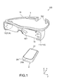
- Fig. 1 is a schematic perspective view showing an information display apparatus according to an embodiment of the present technology.
- An information display apparatus 100 according to this embodiment includes a head-mounted display (HMD) 1 and an input device 2.
- HMD head-mounted display
- input device 2 input device
- the HMD 1 is configured as a see-through HMD in this embodiment.
- the HMD 1 has an eyeglass-shape as a whole. While a user putting the HMD 1 on the head is viewing an outside world, the HMD 1 is configured to be capable of presenting to the user an image based on information output from the input device 2.
- the input device 2 is connected to be wirelessly communicable with the HMD 1.
- the input device 2 may be configured to be communicable with the HMD 1 in a wired manner via a cable or the like.
- the input device 2 is constituted of a portable terminal with a touch panel, for example.
- the input device 2 can be connected also to the Internet and the like.
- the input device 2 may function as a so-called remote controller for the HMD 1 and be configured to be capable of performing input operations for various settings or the like of the HMD 1.
- the input device 2 includes a casing 2A having such a size that the user can hold, for example.
- the casing 2A is an almost-rectangular parallelepiped having a longitudinal direction in an x-axis direction, a lateral direction in a y-axis direction, a thickness direction in the z-axis direction.
- An input operation surface 21 is formed in one surface of the casing 2A.
- the input operation surface 21 belongs to a two-dimensional coordinate system having coordinate axes in an x-axis and a y-axis orthogonal thereto.
- the input operation surface 21 has a rectangular shape perpendicular to a z-axis, which includes long sides parallel to the x-axis direction and short sides parallel to the y-axis direction.
- the input device 2 has a function of detecting, with a finger(s) of the user being a detection target, an xy-coordinate position of the finger on the input operation surface 21 and a change thereof.
- the input device 2 further has a function of detecting an amount of deformation in the z-axis direction of the input operation surface 21 by the finger, that is, a contact pressure.
- the contact pressure of the finger in the z-axis direction against the input operation surface 21 is acquired together with a movement direction, a movement speed, an amount of movement, and the like of the finger on the input operation surface 21.
- the detection target is not limited to the finger of the user, and may be a stylus or the like.
- the input operation surface 21 is constituted of a light-transmissive display cover or the like. An input operation by the detection target is performed on the input operation surface 21.
- the input operation surface 21 also functions as a screen for displaying an image.
- the input operation surface 21 is, for example, provided to cover an opening 21A formed in a surface of the casing 2A and fixed to the casing 2A at a periphery thereof. Further, the material, the thickness, the size, and the like of the input operation surface 21 are set such that the input operation surface 21 can be deformed due to a predetermined contact pressure or higher.
- a transparent plastic plate made of acrylic resin, polycarbonate resin, or PET (polyethylene terephthalate), a glass plate, or a ceramic plate is employed for the material of the input operation surface 21.
- Fig. 2 is a block diagram showing an internal configuration of the input device 2.
- the input device 2 includes a casing 2A, an input operation surface 21, a touch sensor 22, a pressure-sensitive sensor 23, a display element 24, a control unit 25, a storage unit 26, a transmission/reception unit 27, a communication unit 28, and a battery BT.
- the touch sensor 22 and the pressure-sensitive sensor 23 constitute a "sensor unit" in this embodiment.
- the touch sensor 22 has a panel shape with a size almost identical to the input operation surface 21.
- the touch sensor 22 is provided directly below the input operation surface 21 and detects a detection target (finger) in contact with the input operation surface 21.
- the touch sensor 22 detects a coordinate position corresponding to a movement in an xy-plane of the detection target on the input operation surface 21 and outputs a detection signal corresponding to the coordinate position.
- a capacitance touch panel capable of capacitively detecting the detection target in contact with the input operation surface 21 is used as the touch sensor 22.
- the capacitance touch panel may be a projected capacitive type (projection type) or may be a surface capacitive type (surface type).
- the touch sensor 22 of this type typically includes a first sensor 22x for x-position detection in which a plurality of first wires parallel to the y-axis direction are arranged in the x-axis direction and a second sensor 22y for position detection in which a plurality of second wires parallel to the x-axis direction are arranged in the y-axis direction.
- the first and second sensors 22x and 22y are arranged to be opposed to each other in the z-axis direction.
- signal electric current is sequentially supplied by a driving circuit of the control unit 25 to be described later to the first and second wires, for example.
- the touch sensor 22 is not particularly limited as long as it is a sensor capable of detecting the coordinate position of the detection target, various types such as resistive type, an infrared type, an ultrasonic type, a surface acoustic wave type, an acoustic pulse recognition type, and an infrared image sensor are applicable.
- a pressure-sensitive sensor capable of capacitively detecting the contact pressure of the detection target in a Z-axis direction of the input operation surface 21 is used as the pressure-sensitive sensor 23.
- the pressure-sensitive sensor 23 includes, for example, a pair of electrodes or more that are arranged between the input operation surface 21 and the casing 2A and opposed in the z-axis direction, and detects a contact pressure due to a change in capacitance between the electrodes that is caused by deformation of the input operation surface 21.
- one including an elastic body between the pair of electrodes may be employed as the pressure-sensitive sensor 23.
- the contact pressure is detected due to a change in capacitance between the electrodes that is caused by an elastic deformation of the elastic body due to a pushing operation on the input operation surface 21.
- the pressure-sensitive sensor 23 can be driven by the driving circuit of the control unit 25 to be described later, for example.
- the pressure-sensitive sensor 23 is not limited to the above-mentioned configuration.
- a piezoelectric sensor using a piezoelectric element or a strain gauge may also be used.
- the display element 24 is provided directly below the input operation surface 21 and the touch sensor 22.
- the display element 24 in this embodiment is not particularly limited and a liquid-crystal display or an organic EL display can be used. This enables an image of a character, a picture, or the like to be displayed on the input operation surface 21.
- the control unit 25 is, typically, constituted of a CPU (Central Processing Unit) or an MPU (Micro-Processing Unit).
- the control unit 25 includes an arithmetic unit 251 and a signal generation unit 252 and executes various functions according to programs stored in the storage unit 26.
- the arithmetic unit 251 executes predetermined arithmetic processing on electrical signals output from the touch sensor 22 and the pressure-sensitive sensor 23 and generates an operation signal including information on a relative position of the detection target in contact with the input operation surface 21.
- the signal generation unit 252 generates, based on the arithmetic results, an image signal for causing the display element 24 to display an image.
- the control unit 25 includes the driving circuit for driving the touch sensor 22 and the driving circuit is, in this embodiment, incorporated in the arithmetic unit 251.
- the arithmetic unit 251 calculates, based on signals output from the touch sensor 22 and the pressure-sensitive sensor 23, the xy-coordinate position and the contact pressure of the finger on the input operation surface 21. In addition, for example, when it is detected based on the calculation result that the detection target is located at a predetermined xy-coordinate position and a contact pressure equal to or larger than a predetermined threshold is further detected at this coordinate position, the arithmetic unit 251 executes predetermined processing assigned to a GUI corresponding to this coordinate position. The processing results by the arithmetic unit 251 are transmitted to the signal generation unit 252.
- the signal generation unit 252 generates, based on the processing results transmitted from the arithmetic unit 251, an image signal for forming an image to be displayed by the display element 24. At this time, the signal generation unit 252 is also capable of generating a signal for displaying an auxiliary image such as a pointer and an area changed in luminance or intensity at a position corresponding to the xy-coordinate position of the detection target of the image on the input operation surface 21. Further, the signal generation unit 252 is also capable of generating a signal for changing a display mode of the auxiliary image depending on the contact pressure of the detection target.
- the operation signal relating to the xy-coordinate position and the contact pressure calculated by the arithmetic unit 251 of the control unit 25 and the image signal generated by the signal generation unit 252 are configured to be transmitted to the HMD 1 via the transmission/reception unit 27.
- the input device 2 includes an A/D converter that converts the detection signals (analog signals) output from the touch sensor 22 and the pressure-sensitive sensor 23 into digital signals and a D/A converter that converts the digital signals into the analog signals.
- the storage unit 26 is constituted of a RAM (Random Access Memory), a ROM (Read Only Memory), other semiconductor memory, and the like and stores programs or the like used in various calculations by the control unit 25.
- the ROM is constituted of a non-volatile memory and stores programs and setting values for causing the control unit 25 to execute arithmetic processing such as calculation of the xy-coordinate position and the contact pressure.
- the storage unit 26 can store the xy-coordinate position and the contact pressure of the detection target, and programs or the like for executing functions assigned corresponding to them, for example, with a non-volatile semiconductor memory.
- the programs stored in the semiconductor memory or the like in advance may be loaded into the RAM and executed by the arithmetic unit 251 of the control unit 25.
- the transmission/reception unit 27 is configured to be capable of wirelessly transmitting various control signals generated by the control unit 25 to the HMD 1, for example.
- the transmission/reception unit 27 is further configured to be capable of receiving a predetermined signal transmitted from the HMD 2.
- the communication unit 28 is connected to a communication network such as the Internet.
- the communication unit 28 is used in downloading a predetermined program, for example, an application into the input device 2.
- the transmission and reception in the communication unit 28 may be wired via a LAN cable or the like or may be wireless, for example, as a high-speed data communication.
- the battery BT constitutes a power-supply for the input device 2 and supplies a necessary electrical power to the respective units inside the casing 2A.
- the battery BT may be a primary battery or may be a secondary battery.
- the battery BT may be constituted of a solar cell.
- the input device 2 may also include an external switch (not shown) for controlling the actuation or the like of the input device 2 when pressed.
- the HMD 1 is the see-through HMD and configured to be capable of presenting a predetermined image in a field-of-view area while allowing the user to view an outside world.
- the HMD 1 according to this embodiment includes an image display apparatus 11 and a support unit 16.
- the HMD 1 has an eyeglass-shape as a whole. For example, by employing a see-through HMD as the HMD 1, it becomes possible to view the outside world even when the input device 2 is being operated. Thus, the safety during operation can be enhanced.
- the support unit 16 can be mounted on the head of the user. Upon mounting, an image display element 14 to be described later is configured to be supported in front of the eyes of the user. Although the shape of the support unit 16 is not particularly limited, the support unit 16 can be in an eyeglass-shape as a whole in this embodiment.
- the support unit 16 has a temple-like structure that can be mounted on left and right ears of the user, for example.
- a nose pad 161 can be also attached near to a nose bridge of the support unit 16. Further, the support unit 16 may be equipped with earphones 162. For example, metal, alloy, or plastic may be employed for the material of the support unit 16, and not particularly limited.
- the image display apparatus 11 includes a casing 11A and is, for example, located at a predetermined position of the support unit 16.
- the position of the image display apparatus 11 is not particularly limited.
- the image display apparatus 11 is located outside the left and right eyes of the user such that the casing 11A is not included in the field-of-view area of the user.
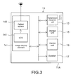
- Fig. 3 is a block diagram showing an internal configuration of the image display apparatus 11.
- the image display apparatus 11 includes the casing 11A, a transmission and reception unit (reception unit) 12, a control unit 13, the image display element 14, and a storage unit 15.
- the control unit 13 constitutes a "display processing unit.”
- the transmission and reception unit 12 receives an operation signal that is output from the transmission/reception unit 27 of the input device 2 and includes information on the xy-coordinate position and the contact pressure of the detection target in contact with the input operation surface 21.
- the image signal of the image displayed on the input operation surface 21 of the input device 2 may also be received.
- a method of transmitting the signal is not particularly limited.
- the wireless communication a communication between apparatuses such as "Wi Fi" (registered trademark), "ZigBee” (registered trademark), and “Bluetooth” (registered trademark) or a communication over the Internet can be used. Alternatively, it may be wired one via a USB (Universal Serial Bus), an HDMI (High-Definition Multimedia Interface), or the like.
- the control unit 13 is typically constituted of the CPU or the MPU and executes various functions according to programs stored in the storage unit 15.
- the control unit 13 generates, based on the operation signal and the image signal received by the transmission and reception unit 12, a control signal for causing the image display element 14 to form an image presented to the user.
- this enables the image display element 14 to display an operation image with an auxiliary image indicating the position of the detection target being overlapped on the same image as the image displayed on the input operation surface 21.
- the shape of the auxiliary image is not particularly limited.
- the auxiliary image is constituted of an annular (ring-like) pointer, an area changed in luminance or intensity, or the like.
- the image display element 14 includes a liquid-crystal display (LCD) element 141 and an optical system 142.
- the image display element 14 is configured to present an image formed by the LCD 141 to the user via the optical system 142.
- the LCD 141 a plurality of pixels are arranged in a matrix form.
- the LCD 141 modulates light input from a light source (not shown) formed of an LED (light-emitting diode) or the like for each pixel according to a control signal generated by the control unit 13.
- the LCD 141 outputs light for forming an image presented to the user.
- the LCD 141 may use, for example, a single-plate method of outputting image light beams corresponding to the colors of R (red), G (green), and B (blue) at the same time or a three-plate method of individually outputting the image light beams corresponding to the colors.
- the optical system 142 is configured to be capable of deflecting light emitted from the LCD 141 to be guided to the eyes of the user.
- the optical system 142 may be constituted of, for example, a light guide plate formed of a transparent substrate capable of guiding light due to a total reflection and a reflective volume hologram diffraction grating capable of performing a diffraction reflection.
- the light guide plate is formed in a rectangular or circular plate-shape or the like and is placed in front of the eyes of the user like lenses of eyeglasses.
- the hologram diffraction grating or the like is appropriately provided in the light guide plate and manufactured to be capable of reflecting light emitted from the LCD 141 to be guided to the eyes of the user.
- a reflection plate or the like may be employed.
- the optical system 142 having such a configuration is capable of presenting the operation image in the field-of-view area of the user because light emitted from the LCD 141 is reflected at a predetermined position.
- the light guide plate is formed of a transparent substrate, and hence it is possible to present the operation image in the field-of-view area in an overlapping manner while allowing the user to view the outside world.
- the storage unit 15 is constituted of the RAM, the ROM, the other semiconductor memory, and the like and stores programs or the like used for various calculations by the control unit 13
- a speaker 17 converts an electrical audio signal, which is transmitted by the input device 2 and generated by the control unit 13 or the like, into a physical vibration and provides the user with sounds via the earphones 162. Note that the configuration of the speaker 17 is not particularly limited.
- the image display apparatus 11 is not limited to a configuration in which two image display apparatuses 11 are provided corresponding to both the eyes.
- a configuration in which one image display apparatus 11 is provided corresponding to only one of the left and right eyes is also possible.
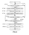
- Fig. 4 is a flowchart in an operation example of the HMD 1 (control unit 13) and the input device 2 (control unit 25).
- Fig. 5 is a diagram explaining a typical operation example of the information display apparatus 100, in which (A) shows the input operation surface 21 of the input device 2, on which the user is performing an input operation, and (B) shows an operation screen presented to the user via the HMD 1.
- an operation example of the information display apparatus 100 when the user wears the HMD 1 and performs a push-in operation at a predetermined position on the input operation surface 21 of the input device 2.
- an X-axis direction and a Y-axis direction in the figures correspond to the x-axis direction and the y-axis direction of the input operation surface 21, respectively, and both indicate orthogonal plane directions.
- the Z-axis direction corresponds to the z-axis direction of the input operation surface 21 and indicates a direction orthogonal to the X-axis direction and the Y-axis direction.
- an image v1 in which a number of GUIs are displayed is displayed ((A) of Fig. 5 ).
- the image v1 is, for example, a menu selection screen of various settings of the HMD 1.
- Each GUI corresponds to switching to a silent mode of the HMD 1, volume control, increase/reduction of the operation image, change of the display mode of the pointer, or the like.
- the input device 2 is configured to be capable of changing the settings of the HMD 1 when the user selects a particular GUI.
- an image V1 similar to the image v1 is presented in the field-of-view area via the HMD 1.
- the input device 2 determines a contact of the finger (detection target) of the user with the input operation surface 21 through the touch sensor 22 (Step ST101). If the contact is detected (YES in Step ST101), the touch sensor 22 outputs the detection signal relating to the xy-coordinate position on the input operation surface 21 with which the finger is in contact, to the control unit 25.
- the arithmetic unit 251 of the control unit 25 calculates the xy-coordinate position of the finger on the input operation surface 21 (Step ST102).
- the signal relating to the xy-coordinate position calculated by the arithmetic unit 251 is output to the transmission/reception unit 27.
- the transmission/reception unit 27 transmits the operation signal relating to the xy-coordinate position to the transmission and reception unit 12 of the HMD 1.
- the control unit 13 of the HMD 1 Based on the operation signal and the image signal received by the transmission and reception unit 12, the control unit 13 of the HMD 1 generates a signal for controlling an operation image V10 with an auxiliary image (pointer P) indicating a position of the detection target being overlapped on the image V1.
- the user by the user checking a movement of the pointer P on the operation image V10 presented by the HMD 1 without needing to view the input operation surface 21 at hand, the user can perform a desired operation.
- the image displayed on the input operation surface 21 may be only the image v1 or may be an image with a pointer or the like being overlapped on the image v1.
- the control unit 25 determines a contact state between the finger and the input operation surface 21 over time (Step ST105).
- the touch sensor 22 outputs a signal when the finger is not in contact.
- the control unit 25 determines a non-contact between the input operation surface 21 and the finger (YES in Step ST105). In this case, the pointer P disappears from the operation image V10 of the HMD 1 and the image V1 is displayed again.
- the touch sensor 22 outputs a signal when the finger is in contact. Based on the output of the touch sensor 22, the control unit 25 determines that the finger of the user is in contact with the input operation surface 21 (NO in Step ST105). After that, based on an output of the pressure-sensitive sensor 21, the contact pressure of the finger against the input operation surface 21 is detected (Step ST106).
- a selection candidate GUI is selected (determined) by a pushing operation of the user on a display position of the selection candidate GUI.
- the control unit 25 Based on the output of the pressure-sensitive sensor 23, the control unit 25 calculates the contact pressure in the arithmetic unit 251. If the calculated contact pressure is equal to or larger than a predetermined threshold (YES in Step ST106), the control unit 25 determines the selection candidate GUI as a selected GUI and acquires code information corresponding to the selected GUI that is stored in the storage unit 26 (Step ST107).
- Step ST106 determines that the selection candidate GUI had not been selected. In this case, the control unit 25 returns to Step ST105 and repeats the above-mentioned processing.
- control unit 25 transmits the acquired code information to the HMD 1 via the transmission/reception unit 27 (Step ST108).
- the control unit 13 of the HMD 1 executes processing corresponding to the selected GUI. This processing is, for example, executed based on a program or the like stored in the storage unit 15. For example, even when the function corresponding to the selected GUI is "switching to silent mode," the control unit 13 can switch the settings of the HMD 1 to the silent mode by executing processing based on the code information corresponding to the GUI.
- the control unit 13 may also generate an image control signal based on the code information and output it to the image display element 14. With this, for example, a new operation image (not shown) overlapped with a volume control bar or the like is presented to the user wearing the HMD 1. In this case, an image control signal generated by the control unit 13 may also be output from the transmission and reception unit 12 to the input device 2. This makes it possible to display an image similar to the new operation image presented by the HMD 1 also on the input operation surface 21 of the input device 2.
- the input device 2 includes the pressure-sensitive sensor 23.
- the input device 1 and the HMD 1 execute processing corresponding to a desired GUI.
- an input operation can also be performed on the input device 2 as it is placed therein.
- the convenience can be enhanced.
- the contact operation with the input operation surface 21 is combined with the push-in operation, a variety of operations can be performed.
- the GUI is not easily selected only by the contact and a false operation can be prevented.
- the HMD 1 it is possible to perform an operation while viewing an image larger than an image displayed on the input operation surface 21 of the input device 2. Therefore, also for elderly people and the like who have difficulties in viewing a small screen, the use of the portable terminal can be facilitated.
- the image v1 is displayed also on the input operation surface 21 of the input device 2.
- the input device 2 is not limited to a device dedicated to the HMD 1 and a portable terminal installing a touch panel display can be connected and used.
- the portable terminal it is possible to use a wide variety of applications of the portable terminal and obtain the above-mentioned actions and effects of the HMD 1.
- Fig. 6 is a flowchart showing an operation example of an information display apparatus according to a second embodiment of the present technology.
- descriptions of portions the same as the configurations and actions of the first embodiment will be omitted or simplified and portions different from the first embodiment will be mainly described.
- the operation image presented by the HMD 1 to the user and the image displayed on the input operation surface 21 are, for example, menu selection images in which a number of GUIs are arranged.
- a different point from the first embodiment is a point that, in Steps ST207 to 212, the control unit 25 can move the auxiliary image (pointer P) and the selected GUI in the operation image presented to the user to a desired position and change the arrangement of the GUIs, for example.
- a "drag and drop" operation is possible.
- Steps ST201 to 206 in Fig. 6 correspond to Steps ST101 to 106 in Fig. 5 , respectively, and hence will be simply described.
- the control unit 25 detects a contact of the finger of the user with the input operation surface 21 (YES in Step ST201) and calculates an xy-coordinate position with which the finger is contact (Step ST202). Based on the xy-coordinate position, the control unit 13 of the HMD 1 displays a pointer P in an image V1 (ST203).
- the control unit 25 of the input device 2 selects a GUI closest to the xy-coordinate position as a candidate (Step ST204).
- the control unit 25 determines a contact state of the finger based on an output of the touch sensor 22 (NO in Step ST205). If determining that the contact pressure in the z-axis direction that is output from the pressure-sensitive sensor 23 is equal to or larger than a threshold (YES in Step ST206), the control unit 25 determines whether or not the contact pressure equal to or larger than the threshold is output for a predetermined period of time or longer (Step ST207).
- Step ST207 With the predetermined period of time or shorter (NO in Step ST207), the control unit 25 returns to Step ST206 and repeats the above-mentioned processing.
- Step ST208 determines the selection candidate GUI as a GUI that can be dragged (hereinafter, referred to as draggable GUI) (Step ST208).
- the control unit 25 calculates the xy-coordinate position detected from the touch sensor 22 over time depending on a movement of the finger on the input operation surface 21 (Step ST209). In addition, this signal is output to the control unit 13 of the HMD 1 via the transmission/reception unit 27 over time. Based on the change of the xy-coordinate position, the control unit 13 generates an image signal for moving the pointer P and the draggable GUI in an image V10 (Step ST210).
- the control unit 25 continues to calculate the contact pressure output from the pressure-sensitive sensor 23 over time and determine whether or not the contact pressure is equal to or larger a threshold (YES in Step ST211). If determining that the contact pressure is smaller than the threshold (NO in Step ST211) and further determining a non-contact with the finger (YES in Step ST212), the control unit 25 executes processing of "dropping" the draggable GUI (Step ST213).
- a position at which the draggable GUI is dropped is a position corresponding to the xy-coordinate position at the point of time when the control unit 25 determines that the contact pressure is smaller than the threshold (NO in Step ST211).
- Step ST214 the control unit 25 returns to Step ST206 and determines whether or not the contact pressure output from the pressure-sensitive sensor 23 is equal to or larger than the threshold again.
- the user can move a GUI, a folder, or the like in the operation image by watching only the operation image of the HMD 1 without needing to check the input operation surface 21 at hand.
- the "drag and drop” operation can be performed and the operability of the user can be enhanced.
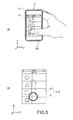
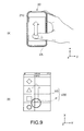
- Figs. 7 to 9 are diagrams explaining a third embodiment of the present technology.
- Fig. 7 is a block diagram showing an internal configuration of an input device according to this embodiment.
- Fig. 8 is a block diagram showing an internal configuration of an image display apparatus according to a head-mounted display according to this embodiment.
- Fig. 9 is a diagram explaining a typical operation example of an information display apparatus, in which (A) shows an input operation surface of the input device, on which the user is performing an input operation, and (B) shows an operation screen presented to the user via the HMD.
- A shows an input operation surface of the input device, on which the user is performing an input operation
- B shows an operation screen presented to the user via the HMD.
- an input device 20 does not include a display element and a control unit and an image is not displayed on an input operation surface 210.
- a detection signal of an xy-coordinate position by a touch sensor 220 and a detection signal of a contact pressure by a pressure-sensitive sensor 230 can be transmitted to an HMD 10 via a transmission/reception unit 270 as an operation signal.
- the image is not displayed on the input operation surface 210 and the input device 20 can be configured to include a so-called touch panel.
- the input device 20 according to this embodiment can be a remote controller dedicated to the HMD 10.
- the input operation surface 210 of the input device 20 can be formed of non-light-transmissive material.
- a synthetic resin or the like that is deformable due to a predetermined contact pressure or higher can be employed.
- a control unit 130 according to an image display apparatus 110 of the HMD 10 includes an arithmetic unit 131 and a display processing unit 132.
- the arithmetic unit 131 calculates an xy-coordinate position and a contact pressure from the detection signal of the xy-coordinate position by the touch sensor 220 and a detection signal of the contact pressure by the pressure-sensitive sensor 230.
- the display processing unit 132 Based on a processing result input from the arithmetic unit 131, the display processing unit 132 generates an image signal for forming an image to be displayed by an image display element 140.
- the display processing unit 132 may also generate a signal for displaying an auxiliary image such as a pointer at a position of the image on the input operation surface 210, which corresponds to the xy-coordinate position of the detection target.
- an auxiliary image such as a pointer at a position of the image on the input operation surface 210, which corresponds to the xy-coordinate position of the detection target.
- the image presented by the HMD 10 to the user may also be acquired from the Internet or the like via a communication unit 280 of the input device 20.
- the HMD 10 may be provided with a communication unit 170 and an image may be generated based on information directly acquired by the HMD 10.
- the configuration of the input device 20 can be simplified. With this, it becomes possible to reduce the size and weight of the input device 20 and to provide the input device 20 that causes less fatigue even in long-term touch operation and is easy to carry.
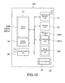
- Fig. 10 is a block diagram showing an internal configuration of an input device according to a fourth embodiment of the present technology.
- this embodiment portions the same as the configurations and actions of the first embodiment will be denoted by the same symbols and the descriptions thereof will be omitted or simplified and portions different from the first embodiment will be mainly described.
- an input device 200 does not include a pressure-sensitive sensor.
- the input device 200 is configured to be capable of detecting a coordinate position corresponding to a movement on an xy-plane of a detection target on the input operation surface 21 through a touch sensor 2200 and detecting a contact pressure.
- the touch sensor 2200 constitutes a "sensor unit.”
- a capacitive touch panel capable of capacitively detecting the detection target in contact with the input operation surface 21 may be used for the touch sensor 2200.
- the touch sensor 2200 detects a coordinate position corresponding to a movement on the xy-plane of the detection target on the input operation surface 21 and outputs a detection signal corresponding to the coordinate position to a control unit 2500.
- the touch sensor 2200 detects a capacitance corresponding to the contact pressure of the detection target and an amount of change. With this, the touch sensor 2200 can output a detection signal corresponding to the contact pressure at the coordinate position.
- a resistive touch panel may also be used.
- a resistive touch sensor 2200 typically includes two transparent electrodes or the like arranged directly below the input operation surface 21 to be opposed via a predetermined gap.
- the resistive touch sensor 2200 outputs a voltage (contact resistance) having a magnitude corresponding to the contact pressure of the detection target.
- the control unit 2500 can calculate the contact pressure of the detection target.
- various touch panel sensors such as an infrared type, an ultrasonic type, and a surface acoustic wave type are applicable as the touch sensor according to this embodiment.
- control unit 2500 is configured to be capable of calculating an xy-coordinate position of the detection target and a contact pressure at this position with the arithmetic unit 2510.
- control unit 2500 an operation example of the input device 200 (control unit 2500) will be simply described.
- an example in which the user selects a particular GUI in the image displayed on the input operation surface 21 and the HMD 1 is shown.
- control unit 2500 acquires a detection signal of the xy-coordinate position from the touch sensor 2200. With this, the control unit 2500 determines a GUI or the like closest to the xy-coordinate position as a selection candidate GUI or the like (see Step ST104 in Fig. 4 ).
- the control unit 2500 determines whether or not the amount of change is equal to or larger than a predetermined threshold (see Step ST106 in Fig. 4 ). If it is equal to or larger than the predetermined threshold, as in the first embodiment, processing corresponding to the selected GUI or the like is performed, for example (see Step ST107 in Fig. 4 ).
- control unit 2500 may also be configured to determine whether or not the capacitance value is equal to or larger than a predetermined threshold.
- the information display apparatus including the input device 200 having the above-mentioned configuration can contribute to a reduction of the costs and an enhancement of the productivity, or the like and reduce the weight and size of the input device 200.
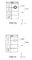
- Figs. 11 to 14 are diagrams explaining a fourth embodiment of the present technology.
- portions the same as the configurations and actions of the first embodiment will be denoted by the same symbols and the descriptions thereof will be omitted or simplified and portions different from the first embodiment will be mainly described.
- This embodiment is different from the first embodiment in that a display mode of an auxiliary image (pointer) P4 (P411 to 422) is changed depending on a contact pressure of a detection target (finger) against the input operation surface 21.
- Figs. 11 and 12 show an example in which an annular pointer P411 on an image V4 becomes larger depending on the contact pressure of the finger.
- an operation image V411 overlapped with the pointer P411 with a predetermined size is displayed ((B) of Fig. 11 ).
- an operation image V412 with a pointer P412 larger than the pointer P411 being overlapped on the image V4 is displayed ((B) of Fig. 12 ).
- the control unit 25 when determining that the contact pressure acquired by the pressure-sensitive sensor 23 is equal to or larger than a predetermined threshold, the control unit 25 outputs this information to the control unit 13 of the HMD 1. With this, the control unit 13 generates a control signal for displaying a pointer with a size depending to the contact pressure. As a result, in the operation images V411 and 412, the pointers P411 and P412 with a size depending on the contact pressure are displayed at positions corresponding to contact positions of the finger with the input operation surface 21.
- Figs. 13 and 14 show an example in which the color of annular pointers P421 and P422 on the image V4 is changed depending on the contact pressure of the finger.
- the operation image V421 with the black pointer P421 is displayed ( Fig. 13 ).
- an operation image V422 with the gray pointer P422 being overlapped on the image V4 is displayed ( Fig. 14 ).
- a transmittance of the annular pointer P4 on the image V4 may also be configured to change depending on the contact pressure of the finger.
- the user can visually check the amount of pushing-in (contact pressure) by himself or herself. This enables the user to more accurately perform an operation combining the contact with the pushing-in by checking the operation image by the HMD 1.
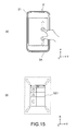
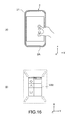
- Figs. 15 and 16 are diagrams explaining a modified example of the second embodiment.
- the information display apparatus 100 is configured to be capable of detecting two or more contact positions on the input operation surface 21 through the touch sensor 22 and the pressure-sensitive sensor 23 of the input device 2.
- a so-called "pinch/zoom" operation of enlarging or reducing images V21 and 22 can be performed.
- the control unit 25 starts a "pinch/zoom." For example, as shown in (A) of Fig. 15 , when the user pushes the two fingers into the input operation surface 21 and widens a distance therebetween, the image V21 can be enlarged depending on the detected distance and change thereof as shown in (B) of Fig. 15 . In contrast, as shown in (A) of Fig. 16 , when the user pushes the two fingers into the input operation surface 211 shortens the distance therebetween, the image V22 can be reduced depending on the detected distance and change thereof as shown in (B) of Fig. 16 .
- the modified example it is possible to change the display area of the image without needing to view the input operation surface 21. This makes it easy to enlarge the display area, for example, when the image V21 is too small to see. In addition, in wishing to watch the outside world, it also becomes possible to more easily view the outside world by reducing the image V22. Thus, it is possible to provide the information display apparatus 100 easier for the user to use even in long-term mounting.
- the "auxiliary image" can be an image of the area changed in luminance, intensity, or the like.
- the control unit 25 calculates an xy-coordinate position of the finger on the input operation surface 21 and outputs this information to the control unit 13 of the HMD 1. Based on the information, the control unit 13 generates a control signal for changing the luminance or intensity of the corresponding XY-coordinate position.
- the HMD 1 can present to the user an operation image different in luminance, intensity, or the like between the area corresponding to the contact position of the finger and the other area.
- the user can check the contact position of the finger or the like on the input operation surface by viewing the operation image displayed by the HMD 1.
- the input device is the portable terminal or the like held and used by the user.
- it is not limited thereto.
- it may be a wrist-watch type attached to the wrist of the user or may be a wrist band type attached to the arm of the user.
- it may be in a form attached or adhering to clothes.
- any type of input device may be used.
- the see-through HMD is used. However, it is not limited thereto. A non-see-through HMD may also be used. Also in this case, the user can perform an intuitive operation without needing to view the input operation surface of the input device by performing an operation while viewing an image presented by the HMD.
- An imaging element may be installed into the HMD and configured to be capable of imaging the outside world. This enables the HMD and the input device to display the captured image, for example.
Landscapes
- Engineering & Computer Science (AREA)
- Theoretical Computer Science (AREA)
- General Engineering & Computer Science (AREA)
- Physics & Mathematics (AREA)
- General Physics & Mathematics (AREA)
- Human Computer Interaction (AREA)
- Computer Hardware Design (AREA)
- Optics & Photonics (AREA)
- User Interface Of Digital Computer (AREA)
- Controls And Circuits For Display Device (AREA)
- Position Input By Displaying (AREA)
Applications Claiming Priority (2)
| Application Number | Priority Date | Filing Date | Title |
|---|---|---|---|
| JP2011282869A JP5957875B2 (ja) | 2011-12-26 | 2011-12-26 | ヘッドマウントディスプレイ |
| PCT/JP2012/007032 WO2013099081A1 (ja) | 2011-12-26 | 2012-11-02 | ヘッドマウントディスプレイ及び情報表示装置 |
Publications (1)
| Publication Number | Publication Date |
|---|---|
| EP2799958A1 true EP2799958A1 (de) | 2014-11-05 |
Family
ID=48696634
Family Applications (1)
| Application Number | Title | Priority Date | Filing Date |
|---|---|---|---|
| EP12862497.0A Withdrawn EP2799958A1 (de) | 2011-12-26 | 2012-11-02 | Kopfmontierte anzeige und informationsanzeigevorrichtung |
Country Status (5)
| Country | Link |
|---|---|
| US (2) | US9779700B2 (de) |
| EP (1) | EP2799958A1 (de) |
| JP (1) | JP5957875B2 (de) |
| CN (1) | CN103999030A (de) |
| WO (1) | WO2013099081A1 (de) |
Cited By (3)
| Publication number | Priority date | Publication date | Assignee | Title |
|---|---|---|---|---|
| WO2015105815A1 (en) * | 2014-01-10 | 2015-07-16 | Microsoft Technology Licensing, Llc | Hover-sensitive control of secondary display |
| DE102014009303A1 (de) * | 2014-06-26 | 2015-12-31 | Audi Ag | Verfahren zum Betreiben einer Virtual-Reality-Brille und System mit einer Virtual-Reality-Brille |
| EP3382508A1 (de) * | 2017-03-14 | 2018-10-03 | Beijing Xiaomi Mobile Software Co., Ltd. | Verfahren und vorrichtung zur steuerung von helmen für virtuelle realität |
Families Citing this family (32)
| Publication number | Priority date | Publication date | Assignee | Title |
|---|---|---|---|---|
| JP5957875B2 (ja) * | 2011-12-26 | 2016-07-27 | ソニー株式会社 | ヘッドマウントディスプレイ |
| CN105210144B (zh) * | 2013-05-21 | 2017-12-08 | 索尼公司 | 显示控制装置、显示控制方法和记录介质 |
| JP6136667B2 (ja) * | 2013-07-08 | 2017-05-31 | コニカミノルタ株式会社 | 画像処理システム、画像形成装置、表示装置、および制御プログラム |
| JP6492419B2 (ja) * | 2014-05-23 | 2019-04-03 | セイコーエプソン株式会社 | 頭部装着型表示装置、頭部装着型表示装置を制御する方法、コンピュータープログラム、画像表示システム、および、情報処理装置 |
| JP5975183B2 (ja) * | 2013-11-01 | 2016-08-23 | 株式会社村田製作所 | 表示装置 |
| CN103631379B (zh) * | 2013-11-21 | 2017-05-31 | 华为终端有限公司 | 触摸选择的视觉反馈方法和装置 |
| JP6024725B2 (ja) * | 2014-01-17 | 2016-11-16 | カシオ計算機株式会社 | システム |
| US9987554B2 (en) * | 2014-03-14 | 2018-06-05 | Sony Interactive Entertainment Inc. | Gaming device with volumetric sensing |
| JP6484079B2 (ja) | 2014-03-24 | 2019-03-13 | 株式会社 ハイディープHiDeep Inc. | 感性伝達方法及びそのための端末機 |
| CN104063092B (zh) * | 2014-06-16 | 2016-12-07 | 青岛歌尔声学科技有限公司 | 一种触摸屏控制方法及装置 |
| KR102283546B1 (ko) * | 2014-10-16 | 2021-07-29 | 삼성전자주식회사 | 웨어러블 디바이스 및 웨어러블 디바이스에서의 어플리케이션 실행 방법 |
| JP5996605B2 (ja) * | 2014-10-21 | 2016-09-21 | 株式会社コロプラ | ヘッドマウントディスプレイとコントローラとを連動させて画面操作するシステム、プログラム、及び方法 |
| US20160196693A1 (en) * | 2015-01-06 | 2016-07-07 | Seiko Epson Corporation | Display system, control method for display device, and computer program |
| JP6548956B2 (ja) * | 2015-05-28 | 2019-07-24 | 株式会社コロプラ | システム、方法、およびプログラム |
| JP6648481B2 (ja) | 2015-10-16 | 2020-02-14 | 凸版印刷株式会社 | 光学素子、光学素子デバイス及び光学素子制御システム |
| WO2017113188A1 (zh) * | 2015-12-30 | 2017-07-06 | 深圳市柔宇科技有限公司 | 头戴式显示设备及其控制方法 |
| US10095266B2 (en) | 2016-01-28 | 2018-10-09 | Colopl, Inc. | System and method for interfacing between a display and a controller |
| CN105739879A (zh) * | 2016-01-29 | 2016-07-06 | 广东欧珀移动通信有限公司 | 一种虚拟现实的应用方法及终端 |
| CN105867635A (zh) * | 2016-04-26 | 2016-08-17 | 乐视控股(北京)有限公司 | 压力触控方法及装置 |
| JP6883394B2 (ja) * | 2016-08-03 | 2021-06-09 | 株式会社コロプラ | プログラム、コンピュータ及び方法 |
| US10152851B2 (en) | 2016-11-29 | 2018-12-11 | Microsoft Technology Licensing, Llc | Notification artifact display |
| CN106547378A (zh) * | 2016-12-07 | 2017-03-29 | 歌尔科技有限公司 | 一种用于vr设备的触控装置和虚拟现实系统 |
| US11054894B2 (en) | 2017-05-05 | 2021-07-06 | Microsoft Technology Licensing, Llc | Integrated mixed-input system |
| JP6285604B2 (ja) * | 2017-06-23 | 2018-02-28 | 晃輝 平山 | 入力装置 |
| US10895966B2 (en) | 2017-06-30 | 2021-01-19 | Microsoft Technology Licensing, Llc | Selection using a multi-device mixed interactivity system |
| US11023109B2 (en) | 2017-06-30 | 2021-06-01 | Microsoft Techniogy Licensing, LLC | Annotation using a multi-device mixed interactivity system |
| JP2019105678A (ja) * | 2017-12-11 | 2019-06-27 | 京セラドキュメントソリューションズ株式会社 | 表示装置、及び画像表示方法 |
| JP2019164431A (ja) * | 2018-03-19 | 2019-09-26 | セイコーエプソン株式会社 | 頭部装着型表示装置、及び頭部装着型表示装置の制御方法 |
| JP7238456B2 (ja) * | 2019-02-21 | 2023-03-14 | セイコーエプソン株式会社 | 表示システム、情報処理装置の制御プログラム、及び情報処理装置の制御方法 |
| US11385789B1 (en) * | 2019-07-23 | 2022-07-12 | Facebook Technologies, Llc | Systems and methods for interacting with displayed items |
| US11106288B1 (en) * | 2020-03-02 | 2021-08-31 | John Walter Downey | Electronic input system |
| WO2022091700A1 (ja) * | 2020-10-27 | 2022-05-05 | 富士フイルム株式会社 | 表示制御装置、表示制御方法、および表示制御プログラム |
Family Cites Families (21)
| Publication number | Priority date | Publication date | Assignee | Title |
|---|---|---|---|---|
| JP2501293B2 (ja) * | 1992-10-29 | 1996-05-29 | インターナショナル・ビジネス・マシーンズ・コーポレイション | 入力装置への圧力の表示方法及びシステム |
| JP2001202192A (ja) * | 2000-01-18 | 2001-07-27 | Sony Corp | 情報処理装置及びその方法並びにプログラム格納媒体 |
| JP2003279881A (ja) * | 2002-03-27 | 2003-10-02 | Hitachi Ltd | 携帯情報装置 |
| JP4115198B2 (ja) * | 2002-08-02 | 2008-07-09 | 株式会社日立製作所 | タッチパネルを備えた表示装置 |
| DE602005023897D1 (de) * | 2004-08-02 | 2010-11-11 | Koninkl Philips Electronics Nv | Berührungsschirm mit druckabhängiger visueller rückmeldung |
| US7683889B2 (en) * | 2004-12-21 | 2010-03-23 | Microsoft Corporation | Pressure based selection |
| JP4797504B2 (ja) * | 2005-08-09 | 2011-10-19 | ソニー株式会社 | 入力装置及びこれを用いた表示装置 |
| JP5023632B2 (ja) | 2006-09-15 | 2012-09-12 | ブラザー工業株式会社 | ヘッドマウントディスプレイ |
| US20080273015A1 (en) * | 2007-05-02 | 2008-11-06 | GIGA BYTE Communications, Inc. | Dual function touch screen module for portable device and opeating method therefor |
| JP2009042967A (ja) * | 2007-08-08 | 2009-02-26 | Nikon Corp | 情報入力表示システム、情報端末および表示装置 |
| JP2009104449A (ja) * | 2007-10-24 | 2009-05-14 | Sharp Corp | カーソル制御装置、カーソル制御システムおよびカーソル制御装置の制御方法 |
| CN101609363B (zh) * | 2008-06-16 | 2011-02-09 | 林志雄 | 输入装置及输入方法 |
| KR101569176B1 (ko) * | 2008-10-30 | 2015-11-20 | 삼성전자주식회사 | 오브젝트 실행 방법 및 장치 |
| JP2010145861A (ja) | 2008-12-19 | 2010-07-01 | Brother Ind Ltd | ヘッドマウントディスプレイ |
| US9891708B2 (en) * | 2009-06-09 | 2018-02-13 | Immersion Corporation | Method and apparatus for generating haptic effects using actuators |
| WO2011019154A2 (en) * | 2009-08-14 | 2011-02-17 | Lg Electronics Inc. | Remote control device and remote control method using the same |
| JP5428943B2 (ja) * | 2010-03-02 | 2014-02-26 | ブラザー工業株式会社 | ヘッドマウントディスプレイ |
| JP5845585B2 (ja) * | 2011-02-04 | 2016-01-20 | セイコーエプソン株式会社 | 情報処理装置 |
| US9152288B2 (en) * | 2011-05-19 | 2015-10-06 | Microsoft Technology Licensing, Llc | Remote multi-touch |
| US20130083003A1 (en) * | 2011-09-30 | 2013-04-04 | Kathryn Stone Perez | Personal audio/visual system |
| JP5957875B2 (ja) * | 2011-12-26 | 2016-07-27 | ソニー株式会社 | ヘッドマウントディスプレイ |
-
2011
- 2011-12-26 JP JP2011282869A patent/JP5957875B2/ja active Active
-
2012
- 2012-11-02 EP EP12862497.0A patent/EP2799958A1/de not_active Withdrawn
- 2012-11-02 CN CN201280063109.9A patent/CN103999030A/zh active Pending
- 2012-11-02 WO PCT/JP2012/007032 patent/WO2013099081A1/ja active Application Filing
- 2012-11-02 US US14/367,030 patent/US9779700B2/en active Active
-
2017
- 2017-09-12 US US15/702,288 patent/US20180005607A1/en not_active Abandoned
Non-Patent Citations (1)
| Title |
|---|
| See references of WO2013099081A1 * |
Cited By (6)
| Publication number | Priority date | Publication date | Assignee | Title |
|---|---|---|---|---|
| WO2015105815A1 (en) * | 2014-01-10 | 2015-07-16 | Microsoft Technology Licensing, Llc | Hover-sensitive control of secondary display |
| DE102014009303A1 (de) * | 2014-06-26 | 2015-12-31 | Audi Ag | Verfahren zum Betreiben einer Virtual-Reality-Brille und System mit einer Virtual-Reality-Brille |
| US9678343B2 (en) | 2014-06-26 | 2017-06-13 | Audi Ag | Method for operating virtual reality glasses and system with virtual reality glasses |
| DE102014009303B4 (de) | 2014-06-26 | 2020-07-23 | Audi Ag | Verfahren zum Betreiben einer Virtual-Reality-Brille und System mit einer Virtual-Reality-Brille |
| EP3382508A1 (de) * | 2017-03-14 | 2018-10-03 | Beijing Xiaomi Mobile Software Co., Ltd. | Verfahren und vorrichtung zur steuerung von helmen für virtuelle realität |
| US10613622B2 (en) | 2017-03-14 | 2020-04-07 | Beijing Xiaomi Mobile Software Co., Ltd. | Method and device for controlling virtual reality helmets |
Also Published As
| Publication number | Publication date |
|---|---|
| US9779700B2 (en) | 2017-10-03 |
| JP2013134532A (ja) | 2013-07-08 |
| US20180005607A1 (en) | 2018-01-04 |
| CN103999030A (zh) | 2014-08-20 |
| WO2013099081A1 (ja) | 2013-07-04 |
| JP5957875B2 (ja) | 2016-07-27 |
| US20150002434A1 (en) | 2015-01-01 |
Similar Documents
| Publication | Publication Date | Title |
|---|---|---|
| EP2799958A1 (de) | Kopfmontierte anzeige und informationsanzeigevorrichtung | |
| US10191281B2 (en) | Head-mounted display for visually recognizing input | |
| CN106168848B (zh) | 显示装置以及显示装置的控制方法 | |
| US10133407B2 (en) | Display apparatus, display system, method for controlling display apparatus, and program | |
| JP6251957B2 (ja) | 表示装置、頭部装着型表示装置および表示装置の制御方法 | |
| JP6264871B2 (ja) | 情報処理装置および情報処理装置の制御方法 | |
| US20150138070A1 (en) | Head-mounted display | |
| CN103217791A (zh) | 头戴式显示器 | |
| WO2015073879A1 (en) | Head tracking based gesture control techniques for head mounted displays | |
| JP2014085954A (ja) | 携帯端末装置、プログラムおよび入力操作受け付け方法 | |
| KR102284369B1 (ko) | 웨어러블 디바이스 및 그 제어 방법 | |
| JP2014106698A (ja) | 表示装置、頭部装着型表示装置および表示装置の制御方法 | |
| KR102405666B1 (ko) | 터치 감지 신호를 제어하는 전자 장치, 방법 및 저장 매체 | |
| CN106155604B (zh) | 显示处理方法和电子设备 | |
| EP3220196B1 (de) | Wearable-vorrichtung | |
| JP2018160239A (ja) | タッチ入力装置及びその制御方法 | |
| JP6740613B2 (ja) | 表示装置、表示装置の制御方法、及び、プログラム | |
| CN106155605B (zh) | 显示处理方法和电子设备 | |
| KR102245374B1 (ko) | 웨어러블 디바이스 및 그 제어 방법 | |
| CN105096905A (zh) | 显示切换方法和电子设备 | |
| JP6176368B2 (ja) | ヘッドマウントディスプレイ及び情報表示装置 | |
| WO2016052061A1 (ja) | ヘッドマウントディスプレイ | |
| JP6754329B2 (ja) | 画像表示装置、ヘッドマウントディスプレイ、情報表示装置、表示処理方法及びプログラム | |
| JP2018092206A (ja) | 頭部装着型表示装置、プログラム、及び頭部装着型表示装置の制御方法 | |
| JP6432583B2 (ja) | 表示装置、頭部装着型表示装置および表示装置の制御方法 |
Legal Events
| Date | Code | Title | Description |
|---|---|---|---|
| PUAI | Public reference made under article 153(3) epc to a published international application that has entered the european phase |
Free format text: ORIGINAL CODE: 0009012 |
|
| 17P | Request for examination filed |
Effective date: 20140604 |
|
| AK | Designated contracting states |
Kind code of ref document: A1 Designated state(s): AL AT BE BG CH CY CZ DE DK EE ES FI FR GB GR HR HU IE IS IT LI LT LU LV MC MK MT NL NO PL PT RO RS SE SI SK SM TR |
|
| STAA | Information on the status of an ep patent application or granted ep patent |
Free format text: STATUS: THE APPLICATION HAS BEEN WITHDRAWN |
|
| 18W | Application withdrawn |
Effective date: 20150127 |