EP2799761A2 - Lichtmodul für einen Kraftfahrzeugscheinwerfer - Google Patents
Lichtmodul für einen Kraftfahrzeugscheinwerfer Download PDFInfo
- Publication number
- EP2799761A2 EP2799761A2 EP14160613.7A EP14160613A EP2799761A2 EP 2799761 A2 EP2799761 A2 EP 2799761A2 EP 14160613 A EP14160613 A EP 14160613A EP 2799761 A2 EP2799761 A2 EP 2799761A2
- Authority
- EP
- European Patent Office
- Prior art keywords
- light
- optics
- diaphragm
- bulge
- module
- Prior art date
- Legal status (The legal status is an assumption and is not a legal conclusion. Google has not performed a legal analysis and makes no representation as to the accuracy of the status listed.)
- Granted
Links
- 230000003287 optical effect Effects 0.000 claims description 25
- 230000002093 peripheral effect Effects 0.000 claims description 8
- 239000004065 semiconductor Substances 0.000 claims description 6
- 230000007704 transition Effects 0.000 claims description 3
- 239000007787 solid Substances 0.000 description 6
- 238000003384 imaging method Methods 0.000 description 5
- 230000001902 propagating effect Effects 0.000 description 4
- 230000004907 flux Effects 0.000 description 3
- 230000000295 complement effect Effects 0.000 description 2
- 230000008878 coupling Effects 0.000 description 2
- 238000010168 coupling process Methods 0.000 description 2
- 238000005859 coupling reaction Methods 0.000 description 2
- 238000001514 detection method Methods 0.000 description 2
- 239000013589 supplement Substances 0.000 description 2
- 238000000149 argon plasma sintering Methods 0.000 description 1
- 239000011248 coating agent Substances 0.000 description 1
- 238000000576 coating method Methods 0.000 description 1
- 230000001427 coherent effect Effects 0.000 description 1
- 239000002131 composite material Substances 0.000 description 1
- 239000004020 conductor Substances 0.000 description 1
- 230000001419 dependent effect Effects 0.000 description 1
- 230000001627 detrimental effect Effects 0.000 description 1
- 230000004313 glare Effects 0.000 description 1
- 239000011521 glass Substances 0.000 description 1
- 238000005286 illumination Methods 0.000 description 1
- 238000002955 isolation Methods 0.000 description 1
- 238000004519 manufacturing process Methods 0.000 description 1
- 239000012994 photoredox catalyst Substances 0.000 description 1
- 229920003229 poly(methyl methacrylate) Polymers 0.000 description 1
- 239000004417 polycarbonate Substances 0.000 description 1
- 239000004926 polymethyl methacrylate Substances 0.000 description 1
- 230000005855 radiation Effects 0.000 description 1
- 239000012780 transparent material Substances 0.000 description 1
Images

Classifications
-
- F—MECHANICAL ENGINEERING; LIGHTING; HEATING; WEAPONS; BLASTING
- F21—LIGHTING
- F21S—NON-PORTABLE LIGHTING DEVICES; SYSTEMS THEREOF; VEHICLE LIGHTING DEVICES SPECIALLY ADAPTED FOR VEHICLE EXTERIORS
- F21S41/00—Illuminating devices specially adapted for vehicle exteriors, e.g. headlamps
- F21S41/10—Illuminating devices specially adapted for vehicle exteriors, e.g. headlamps characterised by the light source
- F21S41/14—Illuminating devices specially adapted for vehicle exteriors, e.g. headlamps characterised by the light source characterised by the type of light source
- F21S41/141—Light emitting diodes [LED]
- F21S41/147—Light emitting diodes [LED] the main emission direction of the LED being angled to the optical axis of the illuminating device
-
- F—MECHANICAL ENGINEERING; LIGHTING; HEATING; WEAPONS; BLASTING
- F21—LIGHTING
- F21S—NON-PORTABLE LIGHTING DEVICES; SYSTEMS THEREOF; VEHICLE LIGHTING DEVICES SPECIALLY ADAPTED FOR VEHICLE EXTERIORS
- F21S41/00—Illuminating devices specially adapted for vehicle exteriors, e.g. headlamps
- F21S41/20—Illuminating devices specially adapted for vehicle exteriors, e.g. headlamps characterised by refractors, transparent cover plates, light guides or filters
- F21S41/25—Projection lenses
- F21S41/275—Lens surfaces, e.g. coatings or surface structures
-
- F—MECHANICAL ENGINEERING; LIGHTING; HEATING; WEAPONS; BLASTING
- F21—LIGHTING
- F21S—NON-PORTABLE LIGHTING DEVICES; SYSTEMS THEREOF; VEHICLE LIGHTING DEVICES SPECIALLY ADAPTED FOR VEHICLE EXTERIORS
- F21S41/00—Illuminating devices specially adapted for vehicle exteriors, e.g. headlamps
- F21S41/20—Illuminating devices specially adapted for vehicle exteriors, e.g. headlamps characterised by refractors, transparent cover plates, light guides or filters
- F21S41/285—Refractors, transparent cover plates, light guides or filters not provided in groups F21S41/24 - F21S41/2805
-
- F—MECHANICAL ENGINEERING; LIGHTING; HEATING; WEAPONS; BLASTING
- F21—LIGHTING
- F21S—NON-PORTABLE LIGHTING DEVICES; SYSTEMS THEREOF; VEHICLE LIGHTING DEVICES SPECIALLY ADAPTED FOR VEHICLE EXTERIORS
- F21S41/00—Illuminating devices specially adapted for vehicle exteriors, e.g. headlamps
- F21S41/30—Illuminating devices specially adapted for vehicle exteriors, e.g. headlamps characterised by reflectors
- F21S41/32—Optical layout thereof
- F21S41/321—Optical layout thereof the reflector being a surface of revolution or a planar surface, e.g. truncated
-
- F—MECHANICAL ENGINEERING; LIGHTING; HEATING; WEAPONS; BLASTING
- F21—LIGHTING
- F21S—NON-PORTABLE LIGHTING DEVICES; SYSTEMS THEREOF; VEHICLE LIGHTING DEVICES SPECIALLY ADAPTED FOR VEHICLE EXTERIORS
- F21S41/00—Illuminating devices specially adapted for vehicle exteriors, e.g. headlamps
- F21S41/30—Illuminating devices specially adapted for vehicle exteriors, e.g. headlamps characterised by reflectors
- F21S41/32—Optical layout thereof
- F21S41/322—Optical layout thereof the reflector using total internal reflection
-
- F—MECHANICAL ENGINEERING; LIGHTING; HEATING; WEAPONS; BLASTING
- F21—LIGHTING
- F21S—NON-PORTABLE LIGHTING DEVICES; SYSTEMS THEREOF; VEHICLE LIGHTING DEVICES SPECIALLY ADAPTED FOR VEHICLE EXTERIORS
- F21S41/00—Illuminating devices specially adapted for vehicle exteriors, e.g. headlamps
- F21S41/30—Illuminating devices specially adapted for vehicle exteriors, e.g. headlamps characterised by reflectors
- F21S41/32—Optical layout thereof
- F21S41/33—Multi-surface reflectors, e.g. reflectors with facets or reflectors with portions of different curvature
- F21S41/334—Multi-surface reflectors, e.g. reflectors with facets or reflectors with portions of different curvature the reflector consisting of patch like sectors
- F21S41/336—Multi-surface reflectors, e.g. reflectors with facets or reflectors with portions of different curvature the reflector consisting of patch like sectors with discontinuity at the junction between adjacent areas
-
- F—MECHANICAL ENGINEERING; LIGHTING; HEATING; WEAPONS; BLASTING
- F21—LIGHTING
- F21S—NON-PORTABLE LIGHTING DEVICES; SYSTEMS THEREOF; VEHICLE LIGHTING DEVICES SPECIALLY ADAPTED FOR VEHICLE EXTERIORS
- F21S41/00—Illuminating devices specially adapted for vehicle exteriors, e.g. headlamps
- F21S41/30—Illuminating devices specially adapted for vehicle exteriors, e.g. headlamps characterised by reflectors
- F21S41/32—Optical layout thereof
- F21S41/33—Multi-surface reflectors, e.g. reflectors with facets or reflectors with portions of different curvature
- F21S41/338—Multi-surface reflectors, e.g. reflectors with facets or reflectors with portions of different curvature the reflector having surface portions added to its general concavity
-
- F—MECHANICAL ENGINEERING; LIGHTING; HEATING; WEAPONS; BLASTING
- F21—LIGHTING
- F21S—NON-PORTABLE LIGHTING DEVICES; SYSTEMS THEREOF; VEHICLE LIGHTING DEVICES SPECIALLY ADAPTED FOR VEHICLE EXTERIORS
- F21S41/00—Illuminating devices specially adapted for vehicle exteriors, e.g. headlamps
- F21S41/30—Illuminating devices specially adapted for vehicle exteriors, e.g. headlamps characterised by reflectors
- F21S41/32—Optical layout thereof
- F21S41/36—Combinations of two or more separate reflectors
- F21S41/365—Combinations of two or more separate reflectors successively reflecting the light
-
- F—MECHANICAL ENGINEERING; LIGHTING; HEATING; WEAPONS; BLASTING
- F21—LIGHTING
- F21S—NON-PORTABLE LIGHTING DEVICES; SYSTEMS THEREOF; VEHICLE LIGHTING DEVICES SPECIALLY ADAPTED FOR VEHICLE EXTERIORS
- F21S41/00—Illuminating devices specially adapted for vehicle exteriors, e.g. headlamps
- F21S41/40—Illuminating devices specially adapted for vehicle exteriors, e.g. headlamps characterised by screens, non-reflecting members, light-shielding members or fixed shades
- F21S41/43—Illuminating devices specially adapted for vehicle exteriors, e.g. headlamps characterised by screens, non-reflecting members, light-shielding members or fixed shades characterised by the shape thereof
-
- F—MECHANICAL ENGINEERING; LIGHTING; HEATING; WEAPONS; BLASTING
- F21—LIGHTING
- F21S—NON-PORTABLE LIGHTING DEVICES; SYSTEMS THEREOF; VEHICLE LIGHTING DEVICES SPECIALLY ADAPTED FOR VEHICLE EXTERIORS
- F21S41/00—Illuminating devices specially adapted for vehicle exteriors, e.g. headlamps
- F21S41/60—Illuminating devices specially adapted for vehicle exteriors, e.g. headlamps characterised by a variable light distribution
- F21S41/65—Illuminating devices specially adapted for vehicle exteriors, e.g. headlamps characterised by a variable light distribution by acting on light sources
- F21S41/663—Illuminating devices specially adapted for vehicle exteriors, e.g. headlamps characterised by a variable light distribution by acting on light sources by switching light sources
-
- F—MECHANICAL ENGINEERING; LIGHTING; HEATING; WEAPONS; BLASTING
- F21—LIGHTING
- F21W—INDEXING SCHEME ASSOCIATED WITH SUBCLASSES F21K, F21L, F21S and F21V, RELATING TO USES OR APPLICATIONS OF LIGHTING DEVICES OR SYSTEMS
- F21W2102/00—Exterior vehicle lighting devices for illuminating purposes
- F21W2102/10—Arrangement or contour of the emitted light
- F21W2102/17—Arrangement or contour of the emitted light for regions other than high beam or low beam
- F21W2102/18—Arrangement or contour of the emitted light for regions other than high beam or low beam for overhead signs
Definitions
- the present invention relates to a light module for a motor vehicle headlight according to the preamble of claim 1.
- Such a light module is from the DE 10 2008 036 192 known and has at least a first light source, a primary optics, a diaphragm and a secondary optics.
- the primary optics is adapted to transfer light emanating from the light source into an intermediate light distribution lying between the primary optics and the secondary optics.
- the diaphragm has a continuous outer edge and an aperture surface, which projects into the intermediate light distribution and which is delimited by an aperture edge.
- the aperture is arranged with respect to the secondary optics so that the diaphragm edge is imaged by the secondary optics as a cut-off in a second light distribution, that of the secondary optics is generated in an apron of the light module as an image of the intermediate light distribution.
- the primary optics is arranged with respect to the secondary optics such that the secondary optic light of the intermediate light distribution, which passes on a first side of the diaphragm at the diaphragm, in a first beam path in one on a first side of the light-dark boundary in the second light distribution distributed area.
- Such a module produces a light distribution with light-dark boundary, such as a dimming or fog light.
- a light module is also suitable, with at least one further light source and a further primary optics, to also generate a high beam distribution using the same secondary optics.
- Such light modules are also known as projection systems. They consist of one or more LEDs as light sources with associated attachment optics as primary optics, a horizontal diaphragm and a projection lens as secondary optics. From the DE 10 2011 004 569 A1 a light module is known which uses a reflector as secondary optics. The invention is also applicable to such light modules.
- the aperture creates a cut-off line that avoids dazzling oncoming vehicles.
- a disadvantage of known projection systems is that only a little light reaches the area above the cut-off line, so that objects such as traffic signs are not sufficiently illuminated.
- On the one hand not to dazzle oncoming vehicles, but on the other hand to ensure adequate detection of objects in this dark area exist statutory requirements that require light intensities between 64 and 625 cd in a range of typically 2 to 4 degrees in the vertical direction and -8 to 8 degrees in the horizontal direction.
- the degrees for the vertical direction refer to deviations from a longitudinal direction of the motor vehicle upwards.
- the degrees for the horizontal direction refer to deviations from the longitudinal direction to the right and left.
- the vertex of the angle is located in the light module.
- the object of the invention is to specify a light module of the type mentioned at the beginning, which light module is a rule-conforming overhead light distribution as a supplement to a rule-compliant Low beam distribution is created without the need for additional components and without affecting the appearance of the module to the outside.
- the light module should also allow the generation of a high beam distribution.
- Objects, such as those from the US Pat. No. 6,736,533 or the EP 624 753 are known, excrete because they block the beam path required for the high beam and usually require an additional component required.
- the present invention differs in that the primary optics is adapted to divert a part of the light emanating from the light source so that it passes on a second side of the diaphragm and outside of the diaphragm and of the Secondary optics is distributed in a second beam path in a lying on a second side of the cut-off in the second light distribution area. For overhead lighting at least contributing light thus passes in particular outside the contiguous outer edge of the aperture.
- the primary optics is arranged with respect to the secondary optics such that the secondary optics light of the intermediate light distribution, which passes on an upper side of the diaphragm at the diaphragm, in a first beam path in one below the light-dark Distributed boundary in the second light distribution area, the primary optics is adapted to divert a portion of the outgoing light from the light source so that it passes in a lying below the diaphragm area at the aperture and the secondary optics in a second beam path in one above the cut-off line is distributed in the second light distribution area.
- the diaphragm surface is preferably aligned substantially parallel to the horizon.
- the first side of the bezel is an upper side.
- the first beam path runs up to the diaphragm edge above the diaphragm surface.
- the area lying on the first side of the light-dark boundary in the second light distribution is the bright area of a low-beam light distribution. In the second light distribution, the bright area is below the cut-off line.
- the second side of the bezel is then a bottom of the bezel.
- the second beam path extends at least as far as the diaphragm edge below the diaphragm surface, and the region lying on the second side of the light-dark boundary in the second light distribution is therefore above this light-dark boundary. This is the darker area of a low beam distribution.
- the so-called overhead area lies in this darker area of the low beam distribution.
- An essential element of the invention is that part of the light emitted by the light source, which is used for the low beam, is directed by the primary optics under the aperture so that it is distributed by the secondary optics in the overhead area.
- the local preposition refers to an orientation of the light module in the room in a proper use of the light module in a motor vehicle, which is on a flat surface.
- Advantages of the invention are that this solution is applicable both for a pure dipped beam module as well as for a combined dipped beam / high beam module. It is also advantageous that the solution requires no additional components and that it does not affect the appearance of the module to the outside.
- the invention provides overhead lighting that complements a low beam distribution and is used, for example, to illuminate gantries.
- a particular advantage is that the invention allows the provision of overhead lighting with a projection module that uses semiconductor light sources with a primary optic and a mirror shutter.
- the invention can be realized by changing the primary optics and requires no changes in secondary optics.
- the secondary optics thus remains unchanged and is illuminated so that it directs light in the direction required for the desired overhead lighting.
- the invention can be used both in light modules that use a projection lens as secondary optics, as well as in light modules that use a reflector as secondary optics.
- the diaphragm preferably extends approximately horizontally between the primary optics and the secondary optics.
- the light source is a semiconductor light source, in particular a light-emitting diode, mounted on a mounting carrier or a printed circuit board.
- a first side of the diaphragm is realized as a reflecting surface. It is also preferred that both sides of the panel are realized as reflecting surfaces.
- a further preferred embodiment is characterized in that the primary optics has a light entry surface having a plurality of partial surfaces, a light exit surface and a light deflecting side surface.
- the light entry surface has a central part and peripheral parts adjacent to the central part and that the light source and the different parts of the light entry surface are arranged relative to each other so that the light undergoes various changes of direction when passing through the optical attachment, which diffraction and Reflection caused.
- the light module is configured such that light whose path is on the first side of the diaphragm, undergoes a refraction at the light entrance, which takes place via a peripheral part of the light entry surface, undergoes an internal total reflection on a side surface and a refraction at Light exits via the light exit surface.
- the attachment optics is set up to allow light which enters the light-conducting material of the attachment optics via the central part of the light entry surface to pass directly to the light exit surface without reflection on a side wall.
- the primary optic has a bulge in its side surface, wherein the bulge lies in a part of the side surface of the attachment optics, which faces the same side as the second side of the diaphragm.
- the bulge is integral with the remaining primary optics and protrudes from the side surface of the rest of the primary optic as a survey and is limited by a bulge side surface and a bulge-light exit surface.
- the bulge lies in a part of the side surface of the attachment optics which is closer to the light exit surface of the primary optic than to the light entry surface.
- the bulge has a light exit surface which adjoins the remaining light exit surface of the bulge, wherein the transition from the light exit surface to the other light exit surface without kink occurs.
- the bulge side surface and the bulge light exit surface are arranged with respect to their alignment with the bulge side surface incident light of the light source so as to direct at least a portion of that light on the second side of the iris at the iris to the secondary optic directed.
- the bulge and in particular its light exit surface is designed such that the overhead region of the light distribution is illuminated by the light emerging from the light exit surface.
- a further preferred embodiment is characterized in that the bulge is realized in each case as a survey from the remaining intent optics.
- At least one attachment optics one Has bulge which is adapted to divert a part of the light emanating from the light source so that it passes on a second side of the diaphragm at the aperture and from the secondary optics in a second beam path in one on a second side of the light-dark Boundary is distributed in the second light distribution lying area, this bulge is left or right of a plane that is spanned by the optical axis of the secondary optics and a vertical.
- Fig. 1 shows in detail a light distribution generated by a light module according to the invention on a measuring screen, wherein the screen is located at a distance of several meters in front of the headlight.
- a light distribution results in a proper use of the light module in a motor vehicle headlight in the motor vehicle.
- Line H corresponds to the height of the horizon in front of the vehicle standing on level ground.
- the line V divides the vehicle apron into a right and a left half space.
- the crossing point HV marks a zero point on both lines, from which deviations in angular degrees are indicated.
- the area 11 represents a rule-compliant light distribution for right-hand traffic.
- the hatched area 11 with large line intervals is brightly illuminated and is bounded above by a light-dark boundary 13.
- This low beam component is used to illuminate the road in front of the vehicle and the areas left and right of the road.
- the cut-off line is asymmetrically high, on the one hand on the left side to avoid dazzling oncoming traffic and on the other hand to achieve the greatest possible range on the own, right side of the road.
- the region 12 which is shaded with smaller line spacings above the cut-off line, represents the so-called overhead area. This area is less brightly illuminated than the area 11 but lighter than surroundings of the areas 11 and 12.
- ECE R112, ECE R123 or SAE FMVSS108 is the overhead range is the range of -8 to +8 degrees in the horizontal direction and +2 to +4 degrees in the vertical direction. In this range, only low light intensities in the range of 64 to 625 cd are required and permissible, so that compliant light modules direct only a small portion of the luminous flux of the light module in this area.
- the light in this area is mainly needed for the recognition of traffic signs. Since these have a high degree of reflection and a high contrast, only little light is required for detection. It is therefore possible to keep glare of oncoming traffic low due to low light intensities in this area and at the same time make it possible to recognize important objects.
- FIG. 2 shows a side view of an embodiment of a light module according to the invention 14 with beam paths 31, 32 of the low-beam component and a beam path 33 of the overhead light component.
- the light module 14 has a light source 21, a front optic 25, a diaphragm 26 and a secondary lens 28 as an embodiment of a secondary optics.
- the light source 21 is preferably a semiconductor light source mounted on a mounting carrier or a printed circuit board, in particular a light-emitting diode. This applies to all light sources mentioned in this application.
- the attachment optics 25 represents an embodiment of a primary optic which, by its arrangement and its optical properties, is adapted to transfer light emerging from the light source 21 into an intermediate light distribution lying between the primary optics and the secondary optics, which is concentrated in a small spatial area.
- the primary optics collects and bundles light emanating from the light source.
- the diaphragm 26 has an aperture surface which projects into the intermediate light distribution and which is delimited by an aperture edge 27.
- the diaphragm 26 is arranged with respect to the secondary optics 28 such that the diaphragm edge 27 is imaged by the secondary optics 28 as a light-dark boundary 13 in a second light distribution, that of the secondary optics 28 in an apron of the light module 18 as an image of the intermediate light distribution is produced.
- the second light distribution is, for example, in the Fig. 1 illustrated light distribution 11.
- the primary optics 25 are arranged with respect to the secondary optics 28 such that the secondary optics 28 light of the intermediate light distribution, which passes on a first side of the diaphragm 26 at the diaphragm, in a first beam path 31, 32 in a on a first side of the light. Dark-border distributed in the second light distribution area. In the FIG. 2 the first side of the diaphragm faces the half space above the diaphragm.
- the first beam path comprises all the light of the light source, which is directed by the primary optics on this first side of the diaphragm at the aperture on the secondary optics.
- the partial beam path 32 in this case comprises the part of the light detected by the primary optics of the light source, which is directed by the primary optics without touching the diaphragm on the first side of the diaphragm and the diaphragm on the secondary optics.
- the partial beam path 31 in this case comprises the part of the light detected by the primary optics of the light source, which is directed by the primary optics via a taking place on the first side of the diaphragm reflection on the diaphragm on the secondary optics.
- the realized here as the top side 19 of the panel 26 is preferably realized as a reflective surface, which can be achieved in particular by a metallic coating. This applies in particular to the part of the first side 19 facing the diaphragm edge 27, since the light intensity of the light incident on the first side is comparatively greatest in the vicinity of the diaphragm edge 27. This results from the fact that the primary optics focus the light in this area.
- the beam paths run past the diaphragm only on the first side of the diaphragm with or without reflection on the first side (upper side).
- the primary optics and the secondary optics are arranged at a distance relative to one another which corresponds to the sum of a secondary-side image length of the primary optics and a primary-side focal length of the secondary optics.
- the diaphragm edge 27 is located in the light path preferably at a distance behind the primary optics, which corresponds to the secondary-side image size of the primary optics and at a distance before the secondary optics, which corresponds to the primary-side focal length of the secondary optics.
- the first side of the aperture 26 is its upwardly facing side.
- the area lying on a first side of the light-dark boundary of the second light distribution is in the FIG. 1 the lying under the light-dark boundary bright area 11, so the low beam distribution.
- the secondary lens 28 forms the intermediate light distribution upside down and mirrored (reversed) on a vertical axis.
- a light module, as in the FIG. 2 is also referred to as a projection module.
- projection modules are characterized in that they image an intermediate light distribution by a secondary optics (usually an imaging lens), which is generated by one or more light sources with matching primary optics (such as reflector or intent optics) in an intermediate image plane, which is at the focus of secondary optics ,
- a diaphragm edge To generate a light-dark boundary is usually a diaphragm edge, which is arranged in the intermediate image plane.
- Known light modules have primary optics and diaphragm arrangements which allow the light to pass only above the diaphragm. In this known manner, in the Fig. 1 shown Abblertztver gutter 11 are generated. However, there can be no light in the overhead area 12 according to FIG. 1 be steered.
- the invention is characterized in that the primary optics is adapted to divert a portion of the outgoing light from the light source 21 so that it passes on a second side 20 of the diaphragm 26 at the aperture and from the secondary optics 28 in a second beam path 33 is distributed in a lying on a second side of the light-dark boundary in the second light distribution area.
- the second beam path encompasses all the light from the light source, which passes from the primary optics on this side of the aperture on the Secondary optics is addressed.
- the secondary optics directs at least part of this light into the overhead area.
- the second side 20 of the bezel 26 is its downwardly facing side.
- the area lying on a second side of the light-dark boundary of the second light distribution is in the FIG. 1 the light region 12 lying above the light-dark boundary, ie the overhead light distribution.
- the secondary lens 28, the intermediate light distribution upside down and mirrored on a vertical axis (reversed) depicts.
- each primary light source is directed in each case to the diaphragm edge.
- the main emission direction of the primary light sources is not parallel to the optical axis of the secondary optics.
- the primary light sources for the low beam function are arranged above the horizontal diaphragm surface.
- the high-beam primary light sources are arranged below the horizontal diaphragm surface.
- the light beam that is generated by the side surface of the bulge runs approximately parallel to the diaphragm surface, so that there is at least one partial light beam from the overhead light bundle that runs parallel to the diaphragm surface.
- the primary optics or attachment optics 25 from the Fig. 2 is a kind of hybrid of an internally totally reflecting reflector and a lens.
- the attachment optical system has a light entry surface having a plurality of partial surfaces 18, 19, a light exit surface 17 and a light deflecting side surface 24, 22 and is made of transparent material such as glass, PC or PMMA.
- the light entrance surface 17 has a central part and peripheral parts adjacent to the central part.
- the light source 21 and the different parts 18, 19 of the light entry surface are arranged relative to each other so that as large a part of the outgoing light from the light source 21 as steeply incident on the light entrance surface 18, that this light is not reflected there but in the light internally totally reflective part of the optical attachment 25 occurs. Overall, the light undergoes various changes in direction when passing through the optical attachment 25, which are caused by refraction or reflection.
- the light propagating in the beam paths 31 and 32 whose path on the first side of the diaphragm (here above) runs along the diaphragm, undergoes a refraction at the light entrance, which takes place via a peripheral part 18 of the light entry surface, an internal total reflection at a side surface 24 and a refraction at the light exit via the light exit surface 17.
- the internal total reflection has the optical attachment in common with a light guide. In contrast to a light guide, however, only very few, preferably only one internal total reflection, occur in a beam path of a front optical system, whereas in the case of a beam path running in an optical waveguide, these are generally much more reflections.
- a light module according to the invention is characterized by a primary optic which is adapted to deflect a part of the light emanating from the light source so that it passes by the diaphragm on a second side of the diaphragm and by the secondary optics second beam path is distributed in a lying on a second side of the light-dark boundary in the second light distribution area.
- the in the FIG. 2 shown attachment optics on a bulge 15 in its side surface 22.
- the bulge 15 lies in a part of the side surface of the attachment optics, which faces the same side as the second side 20 of the diaphragm 26.
- the bulge 15 is preferably integral with the other attachment optics and protrudes as elevation from the side surface 22 of the other attachment optics and is bounded by a bulge side surface 23 and a bulge light exit surface 16.
- the bulge 2 of extending below the dotted line part of the attachment optics.
- the bulge 15 is also located in a part of the side surface which is closer to the light exit surface 17 of the primary optics than at the light entry surface.
- the bulge 15 has a light exit surface 16.
- the light exit surface 16 preferably adjoins the remaining light exit surface 17 of the bulge 15.
- the transition from the light exit surface 16 to the remaining light exit surface 17 preferably takes place without kinking and thus continuously differentiable.
- the angles of incidence of the light incident on the bulge of the light source are fixed.
- the bulge is preferably arranged so that it deflects the incident light in this solid angle to the light exit surface 16 and / or 17 that, taking into account the refraction occurring at the light exit surface 16 and / or 17 passes on the second side of the diaphragm 22 and is distributed by the secondary optics 28 in a second beam path 33 in the area lying on the second side of the cut-off line 13 in the second light distribution. In the FIG. 1 this is the range 12 above the cut-off line.
- the bulge 15 and the illuminated over this bulge 15 Part 16 of the light exit surface of the attachment optics are also designed so that the light is distributed in a rule for overhead lighting angle range.
- Said solid angle, below which the bulge appears viewed from the light source is preferably so large that the light of the light source propagating in it satisfies the light intensity requirements of a rule-compliant overhead lighting. Due to the there only small allowable light intensities there, the light exit surface 16 of the bulge 23 is much smaller than the rest of the light exit surface 17 of the optical attachment 25 and in a composite of several attachment optics primary optics in particular still correspondingly smaller than the light exit surface of the entire primary optics. This results from the fact that preferably less than half of the attachment optics of a primary optics having a plurality of attachment optics are provided with such a bulge.
- FIG. 2 shows an exemplary embodiment of a projection light module according to the invention, which can direct enough light into the overhead region 12.
- the light source 21 emits light, which is focused by the optical attachment 25.
- the attachment optics is designed so that the majority of the light is directed through the bulging side surface 23 of the bulge 15 complementary parts 22, 24 of the side surface of the optical attachment 25 in the area lying above the preferably horizontally disposed aperture 26, while a smaller proportion of the light is deflected by the bulge 15 in the lying below the aperture 26 area.
- the main part of the light is in the FIG. 1 represented by the beam paths 31 and 32, while the lower proportion of the light of the light source 21 is represented by the beam path 33.
- the diaphragm edge 27 shadows part of the light in an intermediate image plane.
- the intermediate image plane lies in the vicinity of the focal point of the secondary lens 28.
- the secondary lens 28 images the light distribution in the intermediate image plane into the environment.
- the rays that are directed across the aperture are imaged by the secondary lens in the low beam region 11.
- the diaphragm edge generates the light-dark boundary 13.
- the surface 23 is designed such that the rays, which are directed under the diaphragm, are imaged by the secondary lens into the overhead region 12.
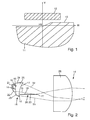
- FIG. 3 shows a perspective view of some components of an embodiment of a light module according to the invention.
- the light of a light source is coupled in each case in exactly one of these light source structurally assigned intent optics.
- the light sources are in the for the FIG. 3 selected representation behind the plane of the drawing and are therefore hidden by the intent optics of the primary optics.
- the arrangement of light source and associated optical attachment corresponds to the reference to the FIG. 2 explained arrangement, but only a single front optics of FIG. 3 have the bulge shown in the figure.
- an additional surface 61 which each of the light exit surface 16 of the associated with FIG. 2 explained bulge 23 corresponds and which serves to direct light in the overhead area. Since the bulges are each realized as elevations from the other optical attachment, the light exit surfaces 16, 61 are additional surfaces which increase the existing without such bulges 23 light exit surfaces 17 of each other intent optics. At this additional light exit surface 61 emerges light, which is directed 26 under the aperture and thus illuminates the overhead area 12, as described in more detail with reference to the FIG. 1 was explained.
- n can also be unequal to 11 and that n depends in particular on the size of the luminous fluxes of the light sources. The larger the luminous flux of a single light source, the smaller n can be.
- FIG. 3 also shows that the arrangement of the n light sources and their n attachment optics takes place on a mounting support having fasteners, here with recessed tabs.
- the mounting bracket forms together with the light sources and their attachment optics a preassembled module, which can also be referred to as a complex light source.
- This complex light source is the subject of FIGS. 3 and 4 a low beam complex light source.
- the complex light source to frame structures of the light module and / or a diaphragm assembly and / or a secondary optics assembly can be fastened, so that there is a defined arrangement of these components with respect to each other.
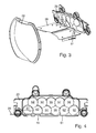
- FIG. 4 shows a view of a light-emitting front of an arrangement of attachment optics of the embodiment of the Fig. 3.
- Figure 4 shows in detail the attachment optics 29 with the light exit surfaces 42,51,52,53,54,55,56,57,58,59,62 of the 11 individual attachment optics.
- the light exit surfaces 42 and 62 of two attachment optics are designed so that they have additional surfaces 41 and 61 which are light exit surfaces of bulges 23 and with which light is directed under the aperture 26.
- a central attachment optics is understood to mean an attachment optics which, when the light module is used as intended, is cut by a plane which is spanned by the optical axis of the secondary optics and by a vertical. This facilitates homogeneous illumination of the overhead area since it is wider in the horizontal direction than in the vertical direction.
- the decentralized arrangement of two protrusions prevents the overhead light beam from being taken out of the part of the light beam of the light source illuminating the center of the light distribution. This is advantageous because in the middle of a light intensity maximum of the low beam distribution is desired.
- At least one attachment optics a bulge which is adapted to divert a portion of the light emanating from the light source so that it passes on a second side of the diaphragm on the aperture and from the secondary optics in a second beam path in is distributed on a second side of the cut-off in the second light distribution area, this bulge is left or right of a plane that is spanned by the optical axis of the secondary optics and a vertical.
- the additional areas 41 and 61 correspond to those associated with the FIG. 2 explained light exit surface 16.
- these additional partial surfaces of the respective light exit surfaces of the attachment optics are below the aperture 26, while the remaining light exit surfaces 51-59 are above the aperture 26.
- Due to the size ratios of the surfaces 41, 61 to the other light exit surfaces also results that the vast majority of the light is directed into the area above the aperture.
- the respective proportion of light in the first approximation can be assumed to be proportional to the respective light exit surface.
- FIG. 5 shows a view of a arranged for coupling of light back of the arrangement of attachment optics of the embodiment of the FIG. 3 ,
- the back side is also the side through which light is coupled into the front optics.
- the direct imaging part corresponds to the optically acting as a lens part of the attachment optics.
- the indirect imaging part corresponds to the part of the optical attachment at whose interface additional total internal reflections occur.
- FIG. 6 shows a side view of such a light module 40 as a further embodiment of a light module according to the invention.
- Fig. 6 shows, in particular, beam paths 31, 32.1, 32.2 of the low beam component, a beam path 33 of the overhead light component and beam paths 101, 102, 103 of an additional component serving to produce a high beam light distribution.
- the high beam component of compared with the subject of the FIG. 2 additional light sources 91 and attachment optics 92 generated.
- the light sources 91 are preferably also semiconductor light sources, in particular light emitting diodes.
- the attachment optics 92 are also preferably transparent solids with a central, acting as a lens part and side surfaces, where take place total internal internal reflections. Also the light entry surface is preferably equally divided into a central part and peripheral parts, as is the subject matter of Fig. 2 was explained. In contrast to the subject of FIG. 2 However, the auxiliary optics 92 participating in the generation of a high-light boundary located above the light-dark boundary of the second light distribution have no bulges that guide light past a different side of the diaphragm 26 than the rest of the respective optical attachment.
- the attachment optics 92 directs all of their structurally associated light source 91 coupled light on the second side 20 of the aperture 26 over. This is illustrated by the beam paths 101, 102 and 103. In the FIG. 6 is the second side of the lower side of the panel, which also corresponds to the arrangement in a proper use of the light module. As can be concluded from the directions of these beam paths after their deflection by the secondary optics 28, this light illuminates above the cut-off line in the Fig. 1 lying areas. The intensity of the light propagating in these beam paths is substantially greater than the intensity of the overhead light propagating in the beam path 33, so that the brightness resulting from the overhead light is completely outshined by the brightness which is generated by the light sources 91.
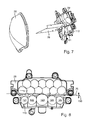
- FIG. 7 shows a perspective view of some components of a light module for generating a low-beam component, an overhead light component and a high-beam component.
- the light module according to Fig. 7 based on the light module of FIG. 3 and, like this, has a low beam complex light source, a screen and a secondary optics in the form of a projection lens.
- the explanations on FIG. 3 also for the subject of FIG. 7
- the subject of the Fig. 7 nor an additional module, which serves as a complex light source 110 for additional light distribution.
- the additional light distribution lies above the horizon and thus supplements the low-beam distribution, which lies substantially below the horizon, to form a high-beam distribution.
- the complex light source 110 has, as well as the complex light source according to FIG. 3 , Fastening structures on. These are as well as the attachment structures of the object the FIG. 3 preferably shaped so that the two complex light sources can be connected to a coherent and inherently rigid assembly, so that an adjustment of the emission directions and a setting in the headlight can always be done together.
- the complex light source can be fastened to frame structures of the light module and / or an aperture assembly and / or a secondary optics assembly with the fastening elements, so that a defined arrangement of these components results in relation to one another.
- the modular design also allows cost-effective production, because, for example, for light modules, the only one Abblertztver whatsoever must (and an overhead light distribution, but not a high beam distribution) generate and for light modules which are also to generate a high beam distribution, the same modules in the form of the low beam complex light source, the diaphragm assembly and the secondary optics can be used.
- FIG. 8 shows a view of a light-emitting front of an array of primary optics of the embodiment of the FIG. 7 .
- FIGS. 6 to 8 illustrated embodiment of a light module according to the invention is characterized in that at the points where the Abbleriumt attachment optics 29 with the help of the surfaces 41 and 61, ie with the aid of the light exit surfaces of bulges of the attachment optics, light under the aperture 26, the lower edge the low beam front optics and the upper edge of the high beam auxiliary optics have a sufficient distance 130 from each other, as in the Fig. 8 is shown.
- this condition has been satisfied by the fact that the auxiliary optics 122, 123 of the high beam assembly, which are arranged below the additional bulges 23 attachment optics of the low beam assembly, smaller than a is central attachment optics of the high beam assembly, which lies between the auxiliary optics 122, 123 of the high beam assembly.
Landscapes
- Engineering & Computer Science (AREA)
- General Engineering & Computer Science (AREA)
- Physics & Mathematics (AREA)
- Microelectronics & Electronic Packaging (AREA)
- Optics & Photonics (AREA)
- Non-Portable Lighting Devices Or Systems Thereof (AREA)
- Lighting Device Outwards From Vehicle And Optical Signal (AREA)
Abstract
Description
- Die vorliegende Erfindung betrifft ein Lichtmodul für einen Kraftfahrzeugscheinwerfer nach dem Oberbegriff des Anspruchs 1.
- Ein solches Lichtmodul ist aus der
DE 10 2008 036 192 bekannt und weist mindestens eine erste Lichtquelle, eine Primäroptik, eine Blende und eine Sekundäroptik auf. Die Primäroptik ist dazu eingerichtet, von der Lichtquelle ausgehendes Licht in eine zwischen der Primäroptik und der Sekundäroptik liegende Zwischenlichtverteilung zu überführen. Die Blende weist einen zusammenhängenden Außenrand und eine Blendenfläche auf, welche in die Zwischenlichtverteilung hineinragt und welche durch eine Blendenkante begrenzt wird. Die Blende ist in Bezug auf die Sekundäroptik so angeordnet, dass die Blendenkante von der Sekundäroptik als Hell-Dunkel-Grenze in einer zweiten Lichtverteilung abgebildet wird, die von der Sekundäroptik in einem Vorfeld des Lichtmoduls als Bild der Zwischenlichtverteilung erzeugt wird. Die Primäroptik ist in Bezug auf die Sekundäroptik so angeordnet, dass die Sekundäroptik Licht der Zwischenlichtverteilung, das auf einer ersten Seite der Blende an der Blende vorbeigelangt, in einem ersten Strahlengang in einen auf einer ersten Seite der Hell-Dunkel-Grenze in der zweiten Lichtverteilung liegenden Bereich verteilt. - Ein solches Modul erzeugt eine Lichtverteilung mit Hell-Dunkel-Grenze wie z.B. ein Abblend- oder Nebellicht. Je nach Ausgestaltung ist ein solches Lichtmodul auch mit wenigstens einer weiteren Lichtquelle und einer weiteren Primäroptik dazu geeignet, unter Verwendung derselben Sekundäroptik auch eine Fernlichtverteilung zu erzeugen.
- Derartige Lichtmodule sind auch als Projektionssysteme bekannt. Sie bestehen aus einer oder mehreren LEDs als Lichtquellen mit zugehörigen Vorsatzoptiken als Primäroptik, einer horizontal liegenden Blende und einer Projektionslinse als Sekundäroptik. Aus der
DE 10 2011 004 569 Al ist ein Lichtmodul bekannt, das einen Reflektor als Sekundäroptik benutzt. Die Erfindung ist auch bei solchen Lichtmodulen verwendbar. Durch die Blende wird eine Hell-Dunkel-Grenze erzeugt, mit der eine Blendung entgegenkommender Fahrzeuge vermieden wird. - Ein Nachteil bekannter Projektionssysteme besteht darin, dass nur wenig Licht in den Bereich oberhalb der Hell-Dunkel-Grenze gelangt, so dass Objekte wie z.B. Verkehrsschilder nicht ausreichend beleuchtet werden. Um einerseits entgegenkommende Fahrzeuge nicht zu blenden, andererseits aber eine ausreichende Erkennung von Objekten in diesem dunklen Bereich sicherzustellen, existieren gesetzliche Vorschriften, die in einem Bereich von typischerweise 2 bis 4 Grad in vertikaler Richtung und -8 bis 8 Grad in horizontaler Richtung Lichtstärken zwischen 64 und 625 cd fordern.
- Dieser Bereich wird häufig als Overheadbereich bezeichnet. Die Gradangaben für die vertikale Richtung beziehen sich dabei auf Abweichungen von einer Längsrichtung des Kraftfahrzeugs nach oben. Die Gradangaben für die horizontale Richtung beziehen sich auf Abweichungen von der Längsrichtung nach rechts und links. Der Scheitel des Winkels befindet sich dabei im Lichtmodul.
- Um solche Lichtstärken in dem Overheadbereich zu erhalten, ist es aus der
EP 1 980 787 bekannt, eine Linse als Sekundäroptik zu verwenden, die Strukturen aufweist, die Licht in den Overheadbereich lenken. Eine ähnliche Lösung ist in derEP 1 464 890 beschrieben. Nachteilig ist dabei jeweils, dass solche Strukturen nach außen für einen Betrachter des Scheinwerfers sichtbar sind, was das Erscheinungsbild des Scheinwerfers beeinträchtigt. Insbesondere bei Nacht sind die Licht streuenden Bereiche der Linse als helle Punkte, Linien oder Flächen für den Betrachter sichtbar und daher nachteilig für das Erscheinungsbild des Scheinwerfers. - Bei dem aus der
DE 10 2009 020 593 bekannten Gegenstand wird Licht durch eine Vielzahl kleiner Prismenstrukturen auf einer Linse in den Overheadbereich gelenkt. Auch diese Lösung weist den Nachteil auf, dass die kleinen Prismenstrukturen für den Betrachter des Moduls sichtbar sind. Die Mikroprismen lenken Licht zwar in eine bevorzugte Raumrichtung, aber an ihren Kanten, die bei realen Teilen eine Verrundung aufweisen, wirken die Mikroprismen als streuende Strukturen, die Licht in einen großen Raumwinkelbereich streuen. Dadurch erscheinen die kleinen Prismen im Gegensatz zur restlichen Oberfläche der Linse als hell, wenn man die Linse aus einem Bereich betrachtet, der oberhalb der Hell-Dunkel-Grenze der vom Modul erzeugten Lichtverteilung liegt. Das ist typischerweise der Fall, wenn man von vorne auf ein Auto schaut, dessen Scheinwerfer eine mit solchen Prismenstrukturen versehene Projektionslinse als Sekundäroptik verwendet. Dieses Erscheinungsbild ist häufig unerwünscht. - In der
US 6 736 533 und in derEP 624 753 EP 1 980 787 ) ist, ausgeschlossen ist. Dies liegt daran, dass der für die Fernlichtfunktion erforderliche Strahlengang durch die zusätzliche Blendenplatte zumindest teilweise blockiert werden würde. - In der
US 2009/0303741 ist eine Lösung beschrieben, bei der durch einen Lichtleiter, der zwischen Blende und Sekundärlinse angeordnet ist, Licht in den Overheadbereich gelenkt wird. Nachteilig an dieser Lösung ist es, dass mit dem Lichtleiter mindestens ein zusätzliches optisches Bauteil benötigt wird, was zu erhöhten Kosten führt. - Vor diesem Hintergrund besteht die Aufgabe der Erfindung in der Angabe eines Lichtmoduls der eingangs genannten Art, welches Lichtmodul eine regelkonforme OverheadLichtverteilung als Ergänzung einer regelkonformen Abblendlichtverteilung erzeugt, ohne dass zusätzliche Bauteile benötigt werden und ohne dass das Erscheinungsbild des Moduls nach außen beeinflusst wird. Dabei soll das Lichtmodul auch eine Erzeugung einer Fernlichtverteilung erlauben. Gegenstände, wie sie zum Beispiel aus der
US 6 736 533 oder derEP 624 753 - Diese Aufgabe wird mit den Merkmalen des Anspruchs 1 gelöst. Von dem eingangs genannten Stand der Technik unterscheidet sich die vorliegende Erfindung dadurch, dass die Primäroptik dazu eingerichtet ist, einen Teil des von der Lichtquelle ausgehenden Lichtes so umzulenken, dass es auf einer zweiten Seite der Blende und außen an der Blende vorbei gelangt und von der Sekundäroptik in einem zweiten Strahlengang in einen auf einer zweiten Seite der Hell-Dunkel-Grenze in der zweiten Lichtverteilung liegenden Bereich verteilt wird. Zur Overheadbeleuchtung zumindest beitragendes Licht gelangt also insbesondere außerhalb des zusammenhängenden Außenrandes an der Blende vorbei. Alternativ lässt sich der Sachverhalt auch so beschreiben: Die Primäroptik ist in Bezug auf die Sekundäroptik so angeordnet, dass die Sekundäroptik Licht der Zwischenlichtverteilung, das auf einer oberen Seite der Blende an der Blende vorbeigelangt, in einem ersten Strahlengang in einen unterhalb der Hell-Dunkel-Grenze in der zweiten Lichtverteilung liegenden Bereich verteilt, wobei die Primäroptik dazu eingerichtet ist, einen Teil des von der Lichtquelle ausgehenden Lichtes so umzulenken, dass es in einem unterhalb der Blende liegenden Bereich an der Blende vorbei gelangt und von der Sekundäroptik in einem zweiten Strahlengang in einen oberhalb der Hell-Dunkel-Grenze in der zweiten Lichtverteilung liegenden Bereich verteilt wird.
- Bei einer bestimmungsgemäßen Verwendung des Lichtmoduls in einem Kraftfahrzeug ist zumindest ein Teil der Blendenfläche bevorzugt im Wesentlichen parallel zum Horizont ausgerichtet. In diesem Fall ist die erste Seite der Blende eine obere Seite. Der erste Strahlengang verläuft bis zur Blendenkante oberhalb der Blendenfläche. Der auf der ersten Seite der Hell-Dunkel-Grenze in der zweiten Lichtverteilung liegende Bereich ist der helle Bereich einer Abblendlichtverteilung. In der zweiten Lichtverteilung liegt der helle Bereich unter der Hell-Dunkel-Grenze.
- Die zweite Seite der Blende ist dann eine Unterseite der Blende. Der zweite Strahlengang verläuft zumindest bis zur Blendenkante unterhalb der Blendenfläche und der Bereich, der auf der zweiten Seite der Hell-Dunkel-Grenze in der zweiten Lichtverteilung liegt, liegt damit oberhalb dieser Hell-Dunkel-Grenze. Dies ist der dunklere Bereich einer Abblendlichtverteilung. Der sogenannte Overheadbereich liegt in diesem dunkleren Bereich der Abblendlichtverteilung.
- Ein wesentliches Element der Erfindung besteht darin, dass ein Teil des von der Lichtquelle ausgehenden Lichtes, das für das Abblendlicht verwendet wird, von der Primäroptik so unter die Blende gerichtet wird, dass es von der Sekundäroptik in den Overheadbereich verteilt wird. Die ortsangebende Präposition bezieht sich dabei auf eine Orientierung des Lichtmoduls im Raum bei einer bestimmungsgemäßen Verwendung des Lichtmoduls in einem Kraftfahrzeug, das auf einem ebenen Untergrund steht. Vorteile der Erfindung liegen darin, dass diese Lösung sowohl für ein reines Abblendlichtmodul als auch für ein kombiniertes Abblendlicht-/Fernlichtmodul anwendbar ist. Vorteilhaft ist auch, dass die Lösung keine zusätzlichen Bauteile erfordert und dass sie das Erscheinungsbild des Moduls nach außen nicht beeinträchtigt. Die Erfindung stellt eine Overheadbeleuchtung bereit, die eine Abblendlichtverteilung ergänzt und zum Beispiel zur Beleuchtung von Schilderbrücken dient. Ein besonderer Vorteil liegt darin, dass die Erfindung die Bereitstellung der Overheadbeleuchtung mit einem Projektionsmodul erlaubt, das Halbleiterlichtquellen mit einer Primäroptik und eine Spiegelblende verwendet. Die Erfindung lässt sich durch Änderung der Primäroptik verwirklichen und erfordert keine Änderungen der Sekundäroptik. Die Sekundäroptik bleibt dabei also unverändert und wird so beleuchtet, dass sie Licht in die für die gewünschte Overheadbeleuchtung erforderliche Richtung lenkt. Die Erfindung kann sowohl bei Lichtmodulen verwendet werden, die eine Projektionslinse als Sekundäroptik nutzen, als auch bei Lichtmodulen, die einen Reflektor als Sekundäroptik benutzen.
- Die Blende erstreckt sich bevorzugt zwischen der Primäroptik und der Sekundäroptik etwa horizontal.
- Es ist bevorzugt, dass die Lichtquelle eine auf einem Montageträger oder einer Leiterplatte montierte Halbleiterlichtquelle, insbesondere eine Leuchtdiode ist.
- Bevorzugt ist auch, dass eine erste Seite der Blende als spiegelnde Fläche verwirklicht ist. Bevorzugt ist auch, dass beide Seiten der Blende als spiegelnde Flächen verwirklicht sind.
- Eine weitere bevorzugte Ausgestaltung zeichnet sich dadurch aus, dass die Primäroptik eine mehrere Teilflächen aufweisende Lichteintrittsfläche, eine Lichtaustrittsfläche und eine Licht umlenkende Seitenfläche aufweist.
- Bevorzugt ist auch, dass die Lichteintrittsfläche einen zentralen Teil und an den zentralen Teil angrenzende periphere Teile aufweist und dass die Lichtquelle und die verschiedenen Teile der Lichteintrittsfläche relativ zueinander so angeordnet sind, dass das Licht beim Durchlaufen der Vorsatzoptik verschiedene Richtungsänderungen erfährt, die durch Brechung und Reflexion verursacht werden.
- Ferner ist bevorzugt, dass das Lichtmodul so ausgestaltet ist, dass Licht, dessen Weg auf der ersten Seite der Blende verläuft, eine Brechung beim Lichteintritt erfährt, der über einen peripheren Teil der Lichteintrittsfläche erfolgt, eine interne Totalreflexion an einer Seitenfläche erfährt und eine Brechung beim Lichtaustritt über die Lichtaustrittsfläche erfährt.
- Bevorzugt ist auch, dass die Vorsatzoptik dazu eingerichtet ist, Licht, welches über den zentralen Teil der Lichteintrittsfläche in das Licht leitende Material der Vorsatzoptik eintritt, ohne Reflexion an einer Seitenwand direkt zur Lichtaustrittsfläche gelangen zu lassen.
- Ferner ist bevorzugt, dass die Primäroptik eine Ausbuchtung in ihrer Seitenfläche aufweist, wobei die Ausbuchtung in einem Teil der Seitenfläche der Vorsatzoptik liegt, welcher der gleichen Seite zugewandt ist wie die zweite Seite der Blende.
- Bevorzugt ist auch, dass die Ausbuchtung einstückig mit der übrigen Primäroptik ist und als Erhebung aus der Seitenfläche der übrigen Primäroptik hervorragt und durch eine Ausbuchtungsseitenfläche und eine Ausbuchtungs-Lichtaustrittsfläche begrenzt wird.
- Ferner ist bevorzugt, dass die Ausbuchtung in einem Teil der Seitenfläche der Vorsatzoptik liegt, der sich näher an der Lichtaustrittsfläche der Primäroptik befindet als an der Lichteintrittsfläche.
- Bevorzugt ist auch, dass die Ausbuchtung eine Lichtaustrittsfläche aufweist, die an die übrige Lichtaustrittsfläche der Ausbuchtung angrenzt, wobei der Übergang von der Lichtaustrittsfläche zur übrigen Lichtaustrittsfläche ohne Knick erfolgt.
- Ferner ist bevorzugt, dass die Ausbuchtungsseitenfläche und die Ausbuchtungs-Lichtaustrittsfläche in Bezug auf ihre Ausrichtung zu dem auf die Ausbuchtungsseitenfläche einfallenden Licht der Lichtquelle so angeordnet sind, dass sie wenigstens einen Teil dieses Lichtes auf der zweiten Seite der Blende an der Blende entlang auf die Sekundäroptik richtet.
- Bevorzugt ist auch, dass die Ausbuchtung und insbesondere ihre Lichtaustrittsfläche so gestaltet ist, dass der Overheadbereich der Lichtverteilung durch das aus der Lichtaustrittsfläche austretende Licht beleuchtet wird.
- Eine weitere bevorzugte Ausgestaltung zeichnet sich dadurch aus, dass die Ausbuchtung jeweils als Erhebung aus der übrigen Vorsatzoptik verwirklicht ist.
- Bevorzugt ist auch, dass mindestens eine Vorsatzoptik eine Ausbuchtung aufweist, die dazu eingerichtet ist, einen Teil des von der Lichtquelle ausgehenden Lichtes so umzulenken, dass es auf einer zweiten Seite der Blende an der Blende vorbei gelangt und von der Sekundäroptik in einem zweiten Strahlengang in einen auf einer zweiten Seite der Hell-Dunkel-Grenze in der zweiten Lichtverteilung liegenden Bereich verteilt wird, wobei diese Ausbuchtung links oder rechts von einer Ebene liegt, die von der optischen Achse der Sekundäroptik und einer Vertikalen aufgespannt wird.
- Dies erleichtert die Erzeugung einer Overheadlichtverteilung, die eine ausreichende Breite besitzt.
- Weitere Vorteile ergeben sich aus den abhängigen Ansprüchen, der Beschreibung und den beigefügten Figuren.
- Es versteht sich, dass die vorstehend genannten und nachstehend noch zu erläuternden Merkmale nicht nur in der jeweils angegebenen Kombination, sondern auch in anderen Kombinationen oder in Alleinstellung verwendbar sind, ohne den Rahmen der vorliegenden Erfindung zu verlassen.
- Ausführungsbeispiele der Erfindung sind in den Zeichnungen dargestellt und werden in der nachfolgenden Beschreibung näher erläutert. Dabei zeigen, jeweils in schematischer Form:
- Figur 1
- eine von einem erfindungsgemäßen Lichtmodul erzeugte Lichtverteilung mit einem Abblendlichtanteil und einem Overhead-Lichtanteil;
- Figur 2
- eine Seitenansicht eines Ausführungsbeispiels eines erfindungsgemäßen Lichtmoduls mit Strahlengängen des Abblendlichtanteils und des Overheadlichtanteils;
- Figur 3
- eine perspektivische Darstellung einiger Komponenten eines Ausführungsbeispiels eines erfindungsgemäßen Lichtmoduls;
- Figur 4
- eine Ansicht einer Licht abstrahlenden Vorderseite einer Anordnung von Primäroptiken des Ausführungsbeispiels aus der
Fig. 3 ; - Figur 5
- eine Ansicht einer zur Einkopplung von Licht eingerichteten Rückseite der Anordnung von Primäroptiken und Blende des Ausführungsbeispiels aus der
Figur 3 ; - Fig. 6
- eine Seitenansicht eines weiteren Ausführungsbeispiels eines erfindungsgemäßen Lichtmoduls mit Strahlengängen des Abblendlichtanteils, des Overheadlichtanteils und eines zusätzlichen zur Erzeugung einer Fernlicht-Lichtverteilung dienenden Anteils;
- Figur 7
- eine perspektivische Ansicht einiger Komponenten eines zur Erzeugung eines Abblendlichtanteils, eines Overheadlichtanteils und eines Fernlichtanteils eingerichteten Lichtmoduls; und
- Figur 8
- eine Ansicht einer Licht abstrahlenden Vorderseite einer Anordnung von Primäroptiken des Ausführungsbeispiels aus der
Figur 7 . - Dabei bezeichnen gleiche Bezugszeichen in verschiedenen Figuren jeweils gleiche oder zumindest ihrer Funktion nach gleiche Elemente.
-
Fig. 1 zeigt im Einzelnen eine von einem erfindungsgemäßen Lichtmodul auf einem Messschirm erzeugte Lichtverteilung, wobei sich der Messschirm in einem Abstand von mehreren Metern vor dem Scheinwerfer befindet. Eine solche Lichtverteilung ergibt sich bei einer bestimmungsgemäßen Verwendung des Lichtmoduls in einem Kraftfahrzeugscheinwerfer im Kraftfahrzeug. Die Linie H entspricht der Höhe des Horizonts vor dem auf ebenem Untergrund stehenden Fahrzeug. Die Linie V teilt das Fahrzeugvorfeld in einen rechten und in einen linken Halbraum. Der Kreuzungspunkt HV markiert auf beiden Linien einen Nullpunkt, von dem aus Abweichungen in Winkelgraden angegeben werden. Der Bereich 11 stellt eine regelkonforme Lichtverteilung für Rechtsverkehr dar. Der mit großen Linienabständen schraffierte Bereich 11 ist hell ausgeleuchtet und wird nach oben durch eine Hell-Dunkel-Grenze 13 begrenzt. Dieser Abblendlichtanteil dient zur Ausleuchtung der Straße vor dem Fahrzeug sowie der Bereiche links und rechts von der Straße. Die Hell-Dunkel-Grenze liegt asymmetrisch hoch, um einerseits auf der linken Seite eine Blendung des Gegenverkehrs zu vermeiden und andererseits eine möglichst große Reichweite auf der eigenen, rechten Fahrbahnseite zu erzielen. - Der mit kleineren Linienabständen schraffierte Bereich 12 über der Hell-Dunkel-Grenze stellt den sog. OverheadBereich dar. Dieser Bereich ist weniger hell ausgeleuchtet als der Bereich 11 aber heller als Umgebungen der Bereiche 11 und 12.
- In den Regelungen ECE R112, ECE R123 oder SAE FMVSS108 ist der Overheadbereich der Bereich von -8 bis +8 Grad in horizontaler Richtung und von +2 bis +4 Grad in vertikaler Richtung. In diesem Bereich sind nur geringe Lichtstärken im Bereich von 64 bis 625 cd gefordert und zulässig, so dass regelkonforme Lichtmodule nur einen geringen Anteil des Lichtstroms des Lichtmoduls in diesen Bereich richten. Das Licht in diesem Bereich wird vorwiegend für das Erkennen von Verkehrsschildern benötigt. Da diese einen hohen Reflexionsgrad und einen hohen Kontrast aufweisen, ist zum Erkennen nur wenig Licht nötig. Man kann daher durch geringe Lichtstärken in diesem Bereich eine Blendung des Gegenverkehrs gering halten und gleichzeitig das Erkennen von wichtigen Objekten ermöglichen.
-
Figur 2 zeigt eine Seitenansicht eines Ausführungsbeispiels eines erfindungsgemäßen Lichtmoduls 14 mit Strahlengängen 31, 32 des Abblendlichtanteils und einem Strahlengang 33 des Overheadlichtanteils. Das Lichtmodul 14 weist eine Lichtquelle 21, eine Vorsatzoptik 25, eine Blende 26 und eine Sekundärlinse 28 als Ausgestaltung einer Sekundäroptik auf. - Die Lichtquelle 21 ist bevorzugt eine auf einem Montageträger oder einer Leiterplatte montierte Halbleiterlichtquelle, insbesondere eine Leuchtdiode. Dies gilt für alle in dieser Anmeldung genannten Lichtquellen.
- Die Vorsatzoptik 25 stellt eine Ausgestaltung einer Primäroptik dar, die durch ihre Anordnung und ihre optischen Eigenschaften dazu eingerichtet ist, von der Lichtquelle 21 ausgehendes Licht in eine zwischen der Primäroptik und der Sekundäroptik liegende Zwischenlichtverteilung zu überführen, die auf einen kleinen Raumbereich konzentriert ist. Die Primäroptik sammelt und bündelt dazu von der Lichtquelle ausgehendes Licht.
- Die Blende 26 weist eine Blendenfläche auf, welche in die Zwischenlichtverteilung hineinragt und welche durch eine Blendenkante 27 begrenzt wird.
- Die Blende 26 ist in Bezug auf die Sekundäroptik 28 so angeordnet, dass die Blendenkante 27 von der Sekundäroptik 28 als Hell-Dunkel-Grenze 13 in einer zweiten Lichtverteilung abgebildet wird, die von der Sekundäroptik 28 in einem Vorfeld des Lichtmoduls 18 als Bild der Zwischenlichtverteilung erzeugt wird. Die zweite Lichtverteilung ist zum Beispiel die in der
Fig. 1 dargestellte Lichtverteilung 11. - Die Primäroptik 25 ist in Bezug auf die Sekundäroptik 28 so angeordnet, dass die Sekundäroptik 28 Licht der Zwischenlichtverteilung, das auf einer ersten Seite der Blende 26 an der Blende vorbeigelangt, in einem ersten Strahlengang 31, 32 in einen auf einer ersten Seite der Hell-Dunkel-Grenze in der zweiten Lichtverteilung liegenden Bereich verteilt. In der
Figur 2 ist die erste Seite der Blende dem über der Blende liegenden Halbraum zugewandt. - Der erste Strahlengang umfasst alles Licht der Lichtquelle, das von der Primäroptik auf dieser ersten Seite der Blende an der Blende vorbei auf die Sekundäroptik gerichtet wird.
- Der Teilstrahlengang 32 umfasst dabei den Teil des von der Primäroptik erfassten Lichtes der Lichtquelle, der von der Primäroptik ohne Berührung der Blende auf der ersten Seite der Blende und an der Blende vorbei auf die Sekundäroptik gerichtet wird.
- Der Teilstrahlengang 31 umfasst dabei den Teil des von der Primäroptik erfassten Lichtes der Lichtquelle, der von der Primäroptik über eine an der ersten Seite der Blende erfolgende Reflexion an der Blende vorbei auf die Sekundäroptik gerichtet wird.
- Die hier als Oberseite verwirklichte erste Seite 19 der Blende 26 ist bevorzugt als spiegelnde Fläche verwirklicht, was insbesondere durch eine metallische Beschichtung erzielt werden kann. Dies gilt insbesondere für den der Blendenkante 27 zugewandten Teil der ersten Seite 19, da die Lichtstärke des auf die erste Seite auftreffenden Lichtes in der Nähe der Blendenkante 27 vergleichsweise am größten ist. Dies ergibt sich daraus, dass die Primäroptik das Licht in diesen Bereich fokussiert. In bekannten Lichtmodulen verlaufen die Strahlengänge dann, wenn eine Abblendlichtverteilung erzeugt werden soll, nur auf der ersten Seite der Blende mit oder ohne Reflexion an der ersten Seite (Oberseite) an der Blende vorbei.
- Die Primäroptik und die Sekundäroptik sind relativ zueinander in einem Abstand angeordnet, der der Summe einer sekundärseitigen Bildweite der Primäroptik und einer primärseitigen Brennweite der Sekundäroptik entspricht. Die Blendenkante 27 befindet sich im Lichtweg bevorzugt in einem Abstand hinter der Primäroptik, welcher der sekundärseitigen Bildweite der Primäroptik entspricht und in einem Abstand vor der Sekundäroptik, welcher der primärseitigen Brennweite der Sekundäroptik entspricht.
- In der
Figur 2 ist die erste Seite der Blende 26 ihre nach oben gewandte Seite. Der auf einer ersten Seite der Hell-Dunkel-Grenze der zweiten Lichtverteilung liegende Bereich ist in derFigur 1 der unter der Hell-Dunkel-Grenze liegende helle Bereich 11, also die Abblendlichtverteilung. Bei den genannten Abständen und Brennweiten bildet die Sekundärlinse 28 die Zwischenlichtverteilung auf dem Kopf stehend und an einer vertikalen Achse gespiegelt (seitenverkehrt) ab. - Ein Lichtmodul, wie es in der
Figur 2 dargestellt ist, wird auch als Projektionsmodul bezeichnet. Ganz allgemein sind Projektionsmodule dadurch charakterisiert, dass sie eine Zwischenlichtverteilung durch eine Sekundäroptik (meist eine abbildende Linse) abbilden, die durch eine oder mehrere Lichtquellen mit passender Primäroptik (wie Reflektor oder Vorsatzoptik) in einer Zwischenbildebene, die im Brennpunkt der Sekundäroptik liegt, erzeugt wird. Zur Erzeugung einer Helldunkelgrenze dient meist eine Blendenkante, die in der Zwischenbildebene angeordnet ist. Bekannte Lichtmodule weisen Primäroptiken und Blendenanordnungen auf, die das Licht nur oberhalb der Blende passieren lassen. Auf diese bekannte Weise kann die in derFig. 1 dargestellte Abblendlichtverteilung 11 erzeugt werden. Es kann aber kein Licht in den Overheadbereich 12 gemäßFigur 1 gelenkt werden. - Im Unterschied dazu zeichnet sich die Erfindung dadurch aus, dass die Primäroptik dazu eingerichtet ist, einen Teil des von der Lichtquelle 21 ausgehenden Lichtes so umzulenken, dass es auf einer zweiten Seite 20 der Blende 26 an der Blende vorbei gelangt und von der Sekundäroptik 28 in einem zweiten Strahlengang 33 in einen auf einer zweiten Seite der Hell-Dunkel-Grenze in der zweiten Lichtverteilung liegenden Bereich verteilt wird. Der zweite Strahlengang umfasst alles Licht der Lichtquelle, das von der Primäroptik auf dieser Seite der Blende vorbei auf die Sekundäroptik gerichtet wird. Die Sekundäroptik richtet zumindest einen Teil dieses Lichtes in den Overheadbereich.
- In der
Figur 2 ist die zweite Seite 20 der Blende 26 ihre nach unten gewandte Seite. Der auf einer zweiten Seite der Hell-Dunkel-Grenze der zweiten Lichtverteilung liegende Bereich ist in derFigur 1 der oberhalb der Hell-Dunkel-Grenze liegende helle Bereich 12, also die Overheadlichtverteilung. Auch hier gilt, dass die Sekundärlinse 28 die Zwischenlichtverteilung auf dem Kopf stehend und an einer vertikalen Achse gespiegelt (seitenverkehrt) abbildet. - Mit Blick auf die Anordnung der Blende und der aus je einer Lichtquelle und einer zugeordneten Vorsatzoptik gebildeten Primärlichtquelle ist bevorzugt, dass die Hauptabstrahlrichtung jeder Primärlichtquelle jeweils auf die Blendenkante gerichtet ist. Dabei ist die Hauptabstrahlrichtung der Primärlichtquellen nicht parallel zur optischen Achse der Sekundäroptik. Die Primärlichtquellen für die Abblendlichtfunktion sind oberhalb der horizontalen Blendenfläche angeordnet. Bei einem auch für eine Erzeugung einer Fernlichtverteilung eingerichteten Lichtmodul, wie es in
Figur 6 gezeigt ist, sind die Fernlicht-Primärlichtquellen unterhalb der horizontalen Blendenfläche angeordnet. - Das Lichtbündel, das von der Seitenfläche der Ausbuchtung erzeugt wird, verläuft annähend parallel zur Blendenfläche, so dass es mindestens ein Teillichtbündel aus dem Overheadlichtbündel gibt, das parallel zur Blendenfläche verläuft.
- Die Primäroptik oder Vorsatzoptik 25 aus der
Fig. 2 ist gewissermaßen ein Hybrid aus einem intern total reflektierenden Reflektor und einer Linse. Die Vorsatzoptik weist eine mehrere Teilflächen 18, 19 aufweisende Lichteintrittsfläche, eine Lichtaustrittsfläche 17 und eine Licht umlenkende Seitenfläche 24, 22 auf und besteht aus transparentem Material wie Glas, PC oder PMMA. Die Lichteintrittsfläche 17 weist einen zentralen Teil und an den zentralen Teil angrenzende periphere Teile auf. Die Lichtquelle 21 und die verschiedenen Teile 18, 19 der Lichteintrittsfläche sind relativ zueinander so angeordnet, dass ein möglichst großer Teil des von der Lichtquelle 21 ausgehenden Lichtes so steil auf die Lichteintrittsfläche 18 auftrifft, dass dieses Licht dort nicht reflektiert wird sondern in den Licht intern total reflektierenden Teil der Vorsatzoptik 25 eintritt. Insgesamt erfährt das Licht beim Durchlaufen der Vorsatzoptik 25 verschiedene Richtungsänderungen, die durch Brechung oder Reflexion verursacht werden. - So erfährt zum Beispiel das in den Strahlengängen 31 und 32 propagierende Licht, dessen Weg auf der ersten Seite der Blende (hier oberhalb) an der Blende entlang verläuft, eine Brechung beim Lichteintritt, der über einen peripheren Teil 18 der Lichteintrittsfläche erfolgt, eine interne Totalreflexion an einer Seitenfläche 24 und eine Brechung beim Lichtaustritt über die Lichtaustrittsfläche 17. Die interne Totalreflexion hat die Vorsatzoptik mit einem Lichtleiter gemeinsam. Im Unterschied zu einem Lichtleiter treten in einem Strahlengang einer Vorsatzoptik aber nur sehr wenige, bevorzugt nur eine interne Totalreflexion auf, während es bei einem in einem Lichtleiter verlaufenden Strahlengang in der Regel sehr viel mehr Reflexionen sind.
- Ferner gibt es Licht, welches über den zentralen Teil 19 oder einen peripheren Teil 18 der Lichteintrittsfläche in den Licht brechenden Teil der Vorsatzoptik 25 eintritt und ohne Reflexion an einer Seitenwand direkt zur Lichtaustrittsfläche 17 gelangt. Dieses Licht wird daher wie beim Durchlaufen einer herkömmlichen Linse zweimal gebrochen.
- Wie bereits erwähnt wurde, zeichnet sich ein erfindungsgemäßes Lichtmodul durch eine Primäroptik aus, die dazu eingerichtet ist, einen Teil des von der Lichtquelle ausgehenden Lichtes so umzulenken, dass es auf einer zweiten Seite der Blende an der Blende vorbei gelangt und von der Sekundäroptik in einem zweiten Strahlengang in einen auf einer zweiten Seite der Hell-Dunkel-Grenze in der zweiten Lichtverteilung liegenden Bereich verteilt wird.
- Zu diesem Zweck weist die in der
Figur 2 dargestellte Vorsatzoptik eine Ausbuchtung 15 in ihrer Seitenfläche 22 auf. Die Ausbuchtung 15 liegt dabei in einem Teil der Seitenfläche der Vorsatzoptik, welcher der gleichen Seite zugewandt ist wie die zweite Seite 20 der Blende 26. Die Ausbuchtung 15 ist bevorzugt einstückig mit der übrigen Vorsatzoptik und ragt als Erhebung aus der Seitenfläche 22 der übrigen Vorsatzoptik hervor und wird durch eine Ausbuchtungsseitenfläche 23 und eine Ausbuchtungs-Lichtaustrittsfläche 16 begrenzt. In derFigur 2 ist die Ausbuchtung 2 der unterhalb der gepunkteten Linie verlaufende Teil der Vorsatzoptik. - In der Ausgestaltung, die in der
Figur 2 dargestellt ist, weist der Teil der Seitenfläche der Vorsatzoptik 25, welcher der gleichen Seite zugewandt ist wie die zweite Seite 20 der Blende 26, neben der Ausbuchtungsseitenfläche 23 noch eine zur Ausbuchtungsseitenfläche 23 komplementäre Teilfläche 22 auf, die auf sie einfallendes Licht so reflektiert, dass dieses Licht in dem ersten Strahlengang propagiert. In derFigur 2 ist diese gleiche Seite die untere Seite. - Die Ausbuchtung 15 liegt ferner in einem Teil der Seitenfläche, der sich näher an der Lichtaustrittsfläche 17 der Primäroptik befindet als an der Lichteintrittsfläche.
- Die Ausbuchtung 15 weist eine Lichtaustrittsfläche 16 auf. Die Lichtaustrittsfläche 16 grenzt bevorzugt an die übrige Lichtaustrittsfläche 17 der Ausbuchtung 15 an. Der Übergang von der Lichtaustrittsfläche 16 zur übrigen Lichtaustrittsfläche 17 erfolgt bevorzugt ohne Knick und damit stetig differenzierbar.
- Durch den Raumwinkel, unter dem die Ausbuchtung 15 und insbesondere ihre umlenkende Seitenfläche 23 und ihre Lichtaustrittsfläche 16 von der Lichtquelle 21 aus betrachtet erscheint, sind die Einfallswinkel des auf die Ausbuchtung einfallenden Lichtes der Lichtquelle festgelegt.
- Die Ausbuchtung ist bevorzugt so angeordnet, dass sie das in diesem Raumwinkel einfallende Licht so zur Lichtaustrittsfläche 16 und/oder 17 umlenkt, dass es unter Berücksichtigung der an der Lichtaustrittsfläche 16 und/oder 17 erfolgenden Brechung auf der zweiten Seite der Blende 22 vorbei gelangt und von der Sekundäroptik 28 in einem zweiten Strahlengang 33 in den auf der zweiten Seite der Hell-Dunkel-Grenze 13 in der zweiten Lichtverteilung liegenden Bereich verteilt wird. In der
Figur 1 ist dies der oberhalb der Hell-Dunkel-Grenze liegende Bereich 12. Die Ausbuchtung 15 und der über diese Ausbuchtung 15 beleuchtete Teil 16 der Lichtaustrittsfläche der Vorsatzoptik sind darüber hinaus so ausgestaltet, dass das Licht in einen für eine Overheadbeleuchtung regelkonformen Winkelbereich verteilt wird. Der genannte Raumwinkel, unter dem die Ausbuchtung von der Lichtquelle aus betrachtet her erscheint, ist bevorzugt so groß, dass das in ihm propagierende Licht der Lichtquelle den Lichtstärkeanforderungen einer regelkonformen OverheadBeleuchtung genügt. Aufgrund der dort nur geringen zulässigen Lichtstärken ist die Lichtaustrittsfläche 16 der Ausbuchtung 23 viel kleiner als die übrige Lichtaustrittsfläche 17 der Vorsatzoptik 25 und bei einer aus mehreren Vorsatzoptiken zusammengesetzten Primäroptik insbesondere noch entsprechend kleiner als die Lichtaustrittsfläche der gesamten Primäroptik. Dies ergibt sich daraus, dass bevorzugt weniger als die Hälfte der Vorsatzoptiken einer mehrere Vorsatzoptiken aufweisenden Primäroptik mit einer solchen Ausbuchtung versehen sind. - Die
Figur 2 zeigt damit insgesamt ein Ausführungsbeispiel eines erfindungsgemäßen Projektions-Lichtmoduls, das genügend Licht in den Overheadbereich 12 lenken kann. Die Lichtquelle 21 strahlt Licht ab, das durch die Vorsatzoptik 25 gebündelt wird. Die Vorsatzoptik ist so ausgelegt, dass der Hauptanteil des Lichts durch die zur Ausbuchtungsseitenfläche 23 der Ausbuchtung 15 komplementären Teile 22, 24 der Seitenfläche der Vorsatzoptik 25 in den oberhalb der bevorzugt horizontal liegenden Blende 26 liegenden Bereich gelenkt wird, während ein geringerer Anteil an dem Licht durch die Ausbuchtung 15 in den unterhalb der Blende 26 liegenden Bereich umgelenkt wird. - Der Hauptanteil des Lichts wird in der
Figur 1 durch die Strahlengänge 31 und 32 repräsentiert, während der geringere Anteil an dem Licht der Lichtquelle 21 durch den Strahlengang 33 repräsentiert wird. Die Blendenkante 27 schattet in einer Zwischenbildebene einen Teil des Lichtes ab. Die Zwischenbildebene liegt in der Umgebung des Brennpunkts der Sekundärlinse 28. Die Sekundärlinse 28 bildet die Lichtverteilung in der Zwischenbildebene in die Umgebung ab. Die Strahlen, die über die Blende gelenkt werden, werden durch die Sekundärlinse in den Abblendlichtbereich 11 abgebildet. Die Blendenkante erzeugt die Helldunkelgrenze 13. Die Fläche 23 ist so ausgelegt, dass die Strahlen, die unter die Blende gelenkt werden, durch die Sekundärlinse in den Overheadbereich 12 abgebildet werden. -
Figur 3 zeigt eine perspektivische Darstellung einiger Komponenten eines Ausführungsbeispiels eines erfindungsgemäßen Lichtmoduls. Im Einzelnen zeigt dieFigur 3 eine Realisierung eines Lichtmoduls mit einer Komplexlichtquelle, die n = 11 Halbleiterlichtquellen und eine Primäroptik 29 aufweist, die aus n = 11 einzelnen Vorsatzoptiken zusammengesetzt ist. Dabei wird das Licht einer Lichtquelle jeweils in genau eine dieser Lichtquelle baulich zugeordnete Vorsatzoptik eingekoppelt. Die Lichtquellen liegen in der für dieFigur 3 gewählten Darstellung hinter der Zeichnungsebene und werden daher durch die Vorsatzoptiken der Primäroptik verdeckt. Die Anordnung von Lichtquelle und zugehöriger Vorsatzoptik entspricht der unter Bezug auf dieFigur 2 erläuterten Anordnung, wobei aber nur einzelne Vorsatzoptiken derFigur 3 die in der Figur dargestellte Ausbuchtung aufweisen. - Von den elf einzelnen Vorsatzoptiken der
Figur 3 weisen zwei Vorsatzoptiken eine zusätzliche Fläche 61 auf, welche jeweils der Lichtaustrittsfläche 16 der im Zusammenhang mit derFigur 2 erläuterten Ausbuchtung 23 entspricht und die dazu dient, Licht in den Overheadbereich zu lenken. Da die Ausbuchtungen jeweils als Erhebungen aus der übrigen Vorsatzoptik verwirklicht sind, stellen die Lichtaustrittsflächen 16, 61 zusätzliche Flächen dar, welche die ohne solche Ausbuchtungen 23 vorhandenen Lichtaustrittsflächen 17 der jeweils übrigen Vorsatzoptik vergrößern. An dieser zusätzlichen Lichtaustrittsfläche 61 tritt Licht aus, das unter die Blende gelenkt 26 wird und auf diese Weise den Overheadbereich 12 ausleuchtet, wie es im Einzelnen unter Bezug auf dieFigur 1 erläutert wurde. - Es versteht sich, dass n auch ungleich 11 sein kann und dass n insbesondere von der Größe der Lichtströme der Lichtquellen abhängt. Je größer der Lichtstrom einer einzelnen Lichtquelle ist, desto kleiner kann n sein.
-
Figur 3 zeigt auch, dass die Anordnung der n Lichtquellen und ihrer n Vorsatzoptiken auf einem Montageträger erfolgt, der Befestigungselemente, hier mit Ausnehmungen versehene Laschen, aufweist. Der Montageträger bildet zusammen mit den Lichtquellen und deren Vorsatzoptiken eine vormontierbare Baugruppe, die auch als Komplexlichtquelle bezeichnet werden kann. Diese Komplexlichtquelle ist beim Gegenstand derFiguren 3 und 4 eine Abblendlicht-Komplexlichtquelle. Mit den Befestigungselementen ist die Komplexlichtquelle an Rahmenstrukturen des Lichtmoduls und/oder einer Blendenbaugruppe und/oder einer Sekundäroptikbaugruppe befestigbar, so dass sich eine definierte Anordnung dieser Komponenten in Bezug aufeinander ergibt. -
Figur 4 zeigt eine Ansicht einer Licht abstrahlenden Vorderseite einer Anordnung von Vorsatzoptiken des Ausführungsbeispiels aus derFig. 3. Figur 4 zeigt im Einzelnen die Vorsatzoptik 29 mit den Lichtaustrittsflächen 42,51,52,53,54,55,56,57,58,59,62 der 11 einzelnen Vorsatzoptiken. Die Lichtaustrittsflächen 42 und 62 von zwei Vorsatzoptiken sind so gestaltet, dass sie zusätzliche Flächen 41 und 61 aufweisen, die Lichtaustrittsflächen von Ausbuchtungen 23 sind und mit denen Licht unter die Blende 26 gelenkt wird. - Es versteht sich, dass auch mehr als zwei oder auch nur eine der Vorsatzoptiken eine Ausbuchtung 23 besitzen kann. Dies hängt auch von dem Raumwinkel ab, den eine einzelne Ausbuchtung aus dem Abblendlicht der Lichtquellen herausnimmt und in den Overheadbereich lenkt. Bevorzugt werden jedoch Ausgestaltungen mit zwei oder mehr Ausbuchtungen, von denen mindestens eine rechts und mindestens eine links von einer zentralen Vorsatzoptik angeordnet ist. Dabei wird unter einer zentralen Vorsatzoptik eine Vorsatzoptik verstanden, die bei einer bestimmungsgemäßen Verwendung des Lichtmoduls von einer Ebene geschnitten wird, die von der optischen Achse der Sekundäroptik und einer Vertikalen aufgespannt wird. Dies erleichtert eine homogene Ausleuchtung des Overheadbereichs, da dieser in der horizontalen Richtung breiter ist als in der vertikalen Richtung. Darüber hinaus verhindert die dezentrale Anordnung von zwei Ausbuchtungen, dass das Overheadlichtbündel aus dem Teil des Lichtbündels der Lichtquelle herausgenommen wird, mit dem das Zentrum der Lichtverteilung beleuchtet wird. Dies ist vorteilhaft, weil in der Mitte ein Lichtstärkemaximum der Abblendlichtverteilung erwünscht ist.
- Bevorzugt ist, dass mindestens eine Vorsatzoptik, eine Ausbuchtung aufweist, die dazu eingerichtet ist, einen Teil des von der Lichtquelle ausgehenden Lichtes so umzulenken, dass es auf einer zweiten Seite der Blende an der Blende vorbei gelangt und von der Sekundäroptik in einem zweiten Strahlengang in einen auf einer zweiten Seite der Hell-Dunkel-Grenze in der zweiten Lichtverteilung liegenden Bereich verteilt wird, wobei diese Ausbuchtung links oder rechts von einer Ebene liegt, die von der optischen Achse der Sekundäroptik und einer Vertikalen aufgespannt wird.
- Die zusätzlichen Flächen 41 und 61 entsprechen der im Zusammenhang mit der
Figur 2 erläuterten Lichtaustrittsfläche 16. In der Vorderansicht ist, wie auch aus derFigur 2 , klar zu erkennen, dass diese zusätzlichen Teilflächen der jeweiligen Lichtaustrittsflächen der Vorsatzoptiken unterhalb der Blende 26 liegen, während die übrigen Lichtaustrittsflächen 51-59 oberhalb der Blende 26 liegen. Aufgrund der Größenverhältnisse der Flächen 41, 61 zu den übrigen Lichtaustrittsflächen ergibt sich auch, dass der weit überwiegende Anteil des Lichts in den Bereich oberhalb der Blende gelenkt wird. Dabei kann der jeweilige Lichtanteil in erster Näherung als zur jeweiligen Lichtaustrittsfläche proportional angenommen werden. -
Figur 5 zeigt eine Ansicht einer zur Einkopplung von Licht eingerichteten Rückseite der Anordnung von Vorsatzoptiken des Ausführungsbeispiels aus derFigur 3 . Die Rückseite ist in diesem Fall auch die Seite, über die Licht in die Vorsatzoptiken eingekoppelt wird. Von dieser Seite aus strahlen die n = 11 LEDs in die n = 11 einzelnen Vorsatzoptiken. Sichtbar sind die zentralen Teile 81,82,83,84,85,86,87,88,89,45,64 der Lichteintrittsflächen des direkt abbildenden Teils der einzelnen Vorsatzoptiken, die Seitenflächen 71,72,73,74,75,76,77,78,79,43,63 des nicht direkt abbildenden Teils der Vorsatzoptiken, an denen interne Totalreflexionen erfolgen, und außerdem reflektierende Flächen 45,65, die Licht kontrolliert unter die Blende lenken und damit der intern total reflektierenden Grenzfläche der Ausbuchtung 23 aus derFigur 2 entsprechen. - Der direkt abbildende Teil entspricht dabei dem optisch als Linse wirkenden Teil der Vorsatzoptik. Der indirekt abbildende Teil entspricht dem Teil der Vorsatzoptik, an dessen Grenzfläche zusätzlich interne Totalreflexionen erfolgen.
- Besonders vorteilhaft ist die beschriebene Lösung für Lichtmodule, mit denen sowohl eine Abblendlichtverteilung als auch eine Fernlichtverteilung erzeugt werden soll.
-
Figur 6 zeigt eine Seitenansicht eines solchen Lichtmoduls 40 als weiteres Ausführungsbeispiel eines erfindungsgemäßen Lichtmoduls.Fig. 6 zeigt insbesondere Strahlengänge 31, 32.1, 32.2 des Abblendlichtanteils, einen Strahlengang 33 des Overheadlichtanteils und Strahlengänge 101, 102, 103 eines zusätzlichen, zur Erzeugung einer Fernlicht-Lichtverteilung dienenden Anteils. Dabei wird der Fernlichtanteil von im Vergleich mit dem Gegenstand derFigur 2 zusätzlichen Lichtquellen 91 und Vorsatzoptiken 92 erzeugt. Die Lichtquellen 91 sind bevorzugt ebenfalls Halbleiterlichtquellen, insbesondere Leuchtdioden. - Die Vorsatzoptiken 92 sind bevorzugt ebenfalls transparente Festkörper mit einem zentralen, als Linse wirkenden Teil und Seitenflächen, an denen bündelnde interne Totalreflexionen stattfinden. Auch die Lichteintrittsfläche ist bevorzugt genauso in einen zentralen Teil und periphere Teile eingeteilt, wie es beim Gegenstand der
Fig. 2 erläutert wurde. Im Unterschied zum Gegenstand derFigur 2 weisen die an der Erzeugung eines oberhalb der Hell-Dunkel-Grenze der zweiten Lichtverteilung liegenden Fernlichtanteils beteiligten Vorsatzoptiken 92 aber keine Ausbuchtungen auf, die Licht an einer anderen Seite der Blende 26 vorbei lenken, als dies durch den Rest der jeweiligen Vorsatzoptik erfolgt. - Die Vorsatzoptik 92 lenkt sämtliches von ihrer baulich zugeordneten Lichtquelle 91 eingekoppeltes Licht an der zweiten Seite 20 der Blende 26 vorbei. Dies wird durch die Strahlengänge 101, 102 und 103 verdeutlicht. In der
Figur 6 ist die zweite Seite die untere Seite der Blende, was auch der Anordnung bei einer bestimmungsgemäßen Verwendung des Lichtmoduls entspricht. Wie aus den Richtungen dieser Strahlengänge nach deren Umlenkung durch die Sekundäroptik 28 geschlossen werden kann, beleuchtet dieses Licht oberhalb der Hell-Dunkel-Grenze in derFig. 1 liegende Bereiche. Dabei ist die Intensität des in diesen Strahlengängen propagierenden Lichtes wesentlich größer als die Intensität des im Strahlengang 33 propagierenden Overheadlichtes, so dass die aus dem Overheadlicht resultierende Helligkeit von der Helligkeit, die von den Lichtquellen 91 erzeugt wird, völlig überstrahlt wird. -
Figur 7 zeigt eine perspektivische Ansicht einiger Komponenten eines zur Erzeugung eines Abblendlichtanteils, eines Overheadlichtanteils und eines Fernlichtanteils eingerichteten Lichtmoduls. - Das Lichtmodul gemäß
Fig. 7 basiert auf dem Lichtmodul derFigur 3 und weist wie dieses eine Abblendlicht-Komplexlichtquelle, eine Blende und eine Sekundäroptik in Form einer Projektionslinse auf. Insofern gelten die Erläuterungen zurFigur 3 auch für den Gegenstand derFigur 7 . Darüber hinaus weist der Gegenstand derFig. 7 noch eine zusätzliche Baugruppe auf, die als Komplexlichtquelle 110 für eine zusätzliche Lichtverteilung dient. Die zusätzliche Lichtverteilung liegt über dem Horizont und ergänzt damit die im Wesentlichen unterhalb des Horizonts liegende Abblendlichtverteilung zu einer Fernlichtverteilung. Die Komplexlichtquelle 110 weist hier m = 5 Lichtquellen und m = 5 diesen Lichtquellen jeweils ein-eindeutig zugeordnete Vorsatzoptiken auf, von denen jede demnach Licht genau einer der Lichtquellen einkoppelt. - Es versteht sich auch hier, dass die Zahl der Paare aus Lichtquellen und Vorsatzoptiken zum Beispiel von der Lichtstromstärke der Lichtquellen abhängt und daher auch kleiner oder größer als 5 sein kann. Die Komplexlichtquelle 110 weist, wie auch die Komplexlichtquelle gemäß
Figur 3 , Befestigungsstrukturen auf. Diese sind wie auch die Befestigungsstrukturen des Gegenstands derFigur 3 bevorzugt so geformt, dass sich die beiden Komplexlichtquellen zu einer zusammenhängenden und in sich starren Baugruppe verbinden lassen, so dass eine Justage der Abstrahlrichtungen und eine Einstellung im Scheinwerfer immer gemeinsam erfolgen kann. Mit den Befestigungselementen ist die Komplexlichtquelle an Rahmenstrukturen des Lichtmoduls und/oder eine Blendenbaugruppe und/oder einer Sekundäroptikbaugruppe befestigbar, so dass sich eine definierte Anordnung dieser Komponenten in Bezug aufeinander ergibt. - Der modulare Aufbau ermöglicht ferner eine kostengünstige Fertigung, weil zum Beispiel für Lichtmodule, die nur eine Abblendlichtverteilung (und eine Overheadlichtverteilung, nicht aber eine Fernlichtverteilung) erzeugen müssen und für Lichtmodule die zusätzlich noch eine Fernlichtverteilung erzeugen sollen, gleiche Baugruppen in Form der Abblendlicht-Komplexlichtquelle, der Blendenbaugruppe und der Sekundäroptik verwendet werden können.
-
Figur 8 zeigt eine Ansicht einer Licht abstrahlenden Vorderseite einer Anordnung von Primäroptiken des Ausführungsbeispiels aus derFigur 7 . Wie bereits weiter oben unter Bezug auf den Stand der Technik ausgeführt wurde, ist es für ein Lichtmodul, das zusätzlich zu einer Abblendlichtverteilung auch eine Fernlichtverteilung erzeugen soll, nachteilig, wenn eine Erzeugung des Overheadlichtes durch eine zusätzliche Blende zwischen Blende und Sekundärlinse erfolgt. Der Nachteil folgt daraus, dass eine solche zusätzliche Blende den Lichtweg für das Fernlicht zumindest teilweise blockieren würde. - Das in den
Figuren 6 bis 8 dargestellte Ausführungsbeispiel eines erfindungsgemäßen Lichtmoduls zeichnet sich dagegen dadurch aus, dass an den Stellen, wo die Abblendlicht-Vorsatzoptik 29 mit Hilfe der Flächen 41 und 61, also mit Hilfe der Lichtaustrittsflächen von Ausbuchtungen der Vorsatzoptiken, Licht unter die Blende 26 lenkt, der untere Rand der Abblendlicht-Vorsatzoptik und der obere Rand der Fernlicht-Vorsatzoptik einen ausreichenden Abstand 130 voneinander haben, wie er in derFig. 8 dargestellt ist. Bei der dort dargestellten Ausgestaltung wurde diese Bedingung dadurch erfüllt, dass die Vorsatzoptiken 122, 123 der Fernlichtbaugruppe, die unterhalb der zusätzliche Ausbuchtungen 23 aufweisenden Vorsatzoptiken der Abblendlichtbaugruppe angeordnet sind, kleiner als eine zentrale Vorsatzoptik der Fernlichtbaugruppe ist, die zwischen den Vorsatzoptiken 122, 123 der Fernlichtbaugruppe liegt.
Claims (15)
- Lichtmodul (14) für einen Kraftfahrzeugscheinwerfer, mit mindestens einer ersten Lichtquelle (21), einer Primäroptik (25), einer Blende (26) und einer Sekundäroptik (28), wobei die Primäroptik dazu eingerichtet ist, von der Lichtquelle ausgehendes Licht in eine zwischen der Primäroptik und der Sekundäroptik liegende Zwischenlichtverteilung zu überführen, wobei die Blende einen zusammenhängenden Außenrand und eine Blendenfläche aufweist, welche in die Zwischenlichtverteilung hineinragt und welche durch eine Blendenkante (27) begrenzt wird, und wobei die Blende in Bezug auf die Sekundäroptik so angeordnet ist, dass die Blendenkante von der Sekundäroptik als Hell-Dunkel-Grenze (13) in einer zweiten Lichtverteilung abgebildet wird, die von der Sekundäroptik in einem Vorfeld des Lichtmoduls als Bild der Zwischenlichtverteilung erzeugt wird, und wobei die Primäroptik in Bezug auf die Sekundäroptik so angeordnet ist, dass die Sekundäroptik Licht der Zwischenlichtverteilung, das auf einer ersten Seite (19) der Blende an der Blende vorbeigelangt, in einem ersten (31, 32) Strahlengang in einen auf einer ersten Seite der Hell-Dunkel-Grenze in der zweiten Lichtverteilung liegenden Bereich (11) verteilt, dadurch gekennzeichnet, dass die Primäroptik dazu eingerichtet ist, einen Teil des von der Lichtquelle ausgehenden Lichtes so umzulenken, dass es auf einer zweiten Seite 20 der Blende außen an der Blende vorbei gelangt und von der Sekundäroptik in einem zweiten Strahlengang (33) in einen auf einer zweiten Seite (20) der Hell-Dunkel-Grenze in der zweiten Lichtverteilung liegenden Bereich verteilt wird.
- Lichtmodul (14) nach Anspruch 1, dadurch gekennzeichnet, dass die Lichtquelle (21) eine auf einem Montageträger oder einer Leiterplatte montierte Halbleiterlichtquelle, insbesondere eine Leuchtdiode ist.
- Lichtmodul (14) nach einem der vorhergehenden Ansprüche, dadurch gekennzeichnet, dass eine erste Seite der Blende (26) oder beide Seiten der Blende als spiegelnde Fläche verwirklicht sind.
- Lichtmodul (14) nach einem der vorhergehenden Ansprüche, dadurch gekennzeichnet, dass die Primäroptik eine mehrere Teilflächen (18, 19) aufweisende Lichteintrittsfläche, eine Lichtaustrittsfläche (17) und eine Licht umlenkende Seitenfläche (24, 22) aufweist.
- Lichtmodul (14) nach Anspruch 4, dadurch gekennzeichnet, dass die Lichteintrittsfläche (17) einen zentralen Teil und an den zentralen Teil angrenzende periphere Teile aufweist und dass die Lichtquelle (21) und die verschiedenen Teile (18, 19) der Lichteintrittsfläche relativ zueinander so angeordnet sind, dass das Licht beim Durchlaufen der Vorsatzoptik (25) verschiedene Richtungsänderungen erfährt, die durch Brechung und Reflexion verursacht werden.
- Lichtmodul (14) nach einem der vorhergehenden Ansprüche, dadurch gekennzeichnet, dass Licht, dessen Weg auf der ersten Seite der Blende verläuft, eine Brechung beim Lichteintritt erfährt, der über einen peripheren Teil (18) der Lichteintrittsfläche erfolgt, eine interne Totalreflexion an einer Seitenfläche (24) erfährt und eine Brechung beim Lichtaustritt über die Lichtaustrittsfläche (17) erfährt.
- Lichtmodul (14) nach einem der vorhergehenden Ansprüche, dadurch gekennzeichnet, dass die Vorsatzoptik dazu eingerichtet ist, Licht, welches über den zentralen Teil (19) der Lichteintrittsfläche in die Vorsatzoptik (25) eintritt, ohne Reflexion an einer Seitenwand direkt zur Lichtaustrittsfläche (17) gelangen zu lassen.
- Lichtmodul (14) nach einem der vorhergehenden Ansprüche, dadurch gekennzeichnet, dass die Primäroptik eine Ausbuchtung (15) in ihrer Seitenfläche aufweist, wobei die Ausbuchtung (15) in einem Teil der Seitenfläche der Vorsatzoptik liegt, welcher der gleichen Seite zugewandt ist wie die zweite Seite der Blende (26).
- Lichtmodul (14) nach einem der vorhergehenden Ansprüche, dadurch gekennzeichnet, dass die Ausbuchtung (15) einstückig mit der übrigen Primäroptik ist und als Erhebung aus der Seitenfläche der übrigen Primäroptik hervorragt und durch eine Ausbuchtungsseitenfläche (23) und eine Ausbuchtungs-Lichtaustrittsfläche (16) begrenzt wird.
- Lichtmodul (14) nach einem der vorhergehenden Ansprüche, dadurch gekennzeichnet, dass die Ausbuchtung (15) in einem Teil der Seitenfläche der Vorsatzoptik liegt, der sich näher an der Lichtaustrittsfläche (17) der Primäroptik befindet als an der Lichteintrittsfläche.
- Lichtmodul (14) nach einem der vorhergehenden Ansprüche, dadurch gekennzeichnet, dass die Ausbuchtung (15) eine Lichtaustrittsfläche (16) aufweist, die an die übrige Lichtaustrittsfläche (17) der Ausbuchtung (25) angrenzt, wobei der Übergang von der Lichtaustrittsfläche (16) zur übrigen Lichtaustrittsfläche (17) ohne Knick erfolgt.
- Lichtmodul (14) nach einem der vorhergehenden Ansprüche, dadurch gekennzeichnet, dass die Ausbuchtungsseitenfläche und die Ausbuchtungs-Lichtaustrittsfläche in Bezug auf ihre Ausrichtung zu dem auf die Ausbuchtungsseitenfläche einfallenden Licht der Lichtquelle so angeordnet ist, dass sie wenigstens einen Teil dieses Lichtes auf der zweiten Seite der Blende an der Blende entlang auf die Sekundäroptik richtet.
- Lichtmodul (14) nach einem der vorhergehenden Ansprüche, dadurch gekennzeichnet, dass die Ausbuchtung und insbesondere ihre Lichtaustrittsfläche (23) so gestaltet ist, dass der Overheadbereich (12) der Lichtverteilung durch das aus der Lichtaustrittsfläche (23) austretende Licht beleuchtet wird.
- Lichtmodul (14) nach einem der vorhergehenden Ansprüche, dadurch gekennzeichnet, dass die Ausbuchtungen jeweils als Erhebungen aus der übrigen Vorsatzoptik verwirklicht sind.
- Lichtmodul (14) nach einem der vorhergehenden Ansprüche, dadurch gekennzeichnet, dass mindestens eine Vorsatzoptik eine Ausbuchtung (15) aufweist, die dazu eingerichtet ist, einen Teil des von der Lichtquelle ausgehenden Lichtes so umzulenken, dass es auf einer zweiten Seite (20) der Blende an der Blende vorbei gelangt und von der Sekundäroptik in einem zweiten Strahlengang (33) in einen auf einer zweiten Seite (20) der Hell-Dunkel-Grenze in der zweiten Lichtverteilung liegenden Bereich verteilt wird, wobei diese Ausbuchtung (15) links oder rechts von einer Ebene liegt, die von der optischen Achse der Sekundäroptik und einer Vertikalen aufgespannt wird.
Applications Claiming Priority (1)
| Application Number | Priority Date | Filing Date | Title |
|---|---|---|---|
| DE102013207850.1A DE102013207850A1 (de) | 2013-04-29 | 2013-04-29 | Lichtmodul für einen Kraftfahrzeugscheinwerfer |
Publications (3)
| Publication Number | Publication Date |
|---|---|
| EP2799761A2 true EP2799761A2 (de) | 2014-11-05 |
| EP2799761A3 EP2799761A3 (de) | 2016-08-31 |
| EP2799761B1 EP2799761B1 (de) | 2020-10-14 |
Family
ID=50289534
Family Applications (1)
| Application Number | Title | Priority Date | Filing Date |
|---|---|---|---|
| EP14160613.7A Active EP2799761B1 (de) | 2013-04-29 | 2014-03-19 | Lichtmodul für einen kraftfahrzeugscheinwerfer |
Country Status (4)
| Country | Link |
|---|---|
| US (1) | US9249943B2 (de) |
| EP (1) | EP2799761B1 (de) |
| CN (1) | CN104121535B (de) |
| DE (1) | DE102013207850A1 (de) |
Cited By (11)
| Publication number | Priority date | Publication date | Assignee | Title |
|---|---|---|---|---|
| EP3040602A4 (de) * | 2013-08-29 | 2017-03-29 | Ichikoh Industries, Ltd. | Fahrzeuglampe |
| WO2018046321A1 (de) * | 2016-09-08 | 2018-03-15 | Osram Gmbh | Optik und optisches system |
| WO2019197204A1 (de) * | 2018-04-11 | 2019-10-17 | HELLA GmbH & Co. KGaA | Scheinwerfer für fahrzeuge |
| EP3699486A1 (de) * | 2019-02-25 | 2020-08-26 | Marelli Automotive Lighting Reutlingen (Germany) GmbH | Scheinwerfer mit einer mehrzahl von halbleiterlichtquellen und einem einstückigen primäroptikfeld |
| DE102019118968A1 (de) * | 2019-07-12 | 2021-01-14 | HELLA GmbH & Co. KGaA | Projektionsscheinwerfer für Fahrzeuge |
| EP3839327A1 (de) * | 2019-12-20 | 2021-06-23 | ZKW Group GmbH | Projektionsmodul für einen kraftfahrzeugscheinwerfer |
| EP3839324A1 (de) * | 2019-12-16 | 2021-06-23 | ZKW Group GmbH | Beleuchtungsvorrichtung für einen kraftfahrzeugscheinwerfer |
| EP3882514A4 (de) * | 2020-01-20 | 2022-04-06 | Hasco Vision Technology Co., Ltd. | Optisches scheinwerferelement, scheinwerfermodul, fahrzeugleuchte und fahrzeug |
| WO2023006947A1 (fr) * | 2021-07-30 | 2023-02-02 | Valeo Vision | Module d'eclairage de vehicule automobile |
| EP4273440A1 (de) * | 2022-05-04 | 2023-11-08 | Marelli Automotive Lighting Reutlingen (Germany) GmbH | Lichtmodul mit mehreren vorsatzoptiken |
| EP4411219A4 (de) * | 2021-10-01 | 2024-08-07 | Koito Manufacturing Co., Ltd. | Scheinwerfer für fahrzeuge |
Families Citing this family (34)
| Publication number | Priority date | Publication date | Assignee | Title |
|---|---|---|---|---|
| JP6331797B2 (ja) * | 2014-07-14 | 2018-05-30 | ウシオ電機株式会社 | 車載用光源装置 |
| DE102014019344A1 (de) * | 2014-12-22 | 2016-06-23 | GM Global Technology Operations LLC (n. d. Ges. d. Staates Delaware) | Kraftfahrzeugscheinwerfer, Kraftfahrzeugscheinwerfersystem, Kraftfahrzeug sowie Verfahren zum Betrieb eines Kraftfahrzeugs |
| CN104849844A (zh) * | 2015-03-19 | 2015-08-19 | 浙江大学 | 碟式菲涅尔反射聚光方法及其装置 |
| US10851957B2 (en) * | 2015-05-22 | 2020-12-01 | Mitsubishi Electric Corporation | Headlight module and headlight device |
| AT517752B1 (de) * | 2015-09-17 | 2018-04-15 | Zkw Group Gmbh | Lichtmodul für einen kraftfahrzeugscheinwerfer zur abstrahlung einer langreichweitigen lichtverteilung sowie beleuchtungsvorrichtung |
| CN105258057B (zh) * | 2015-11-03 | 2017-11-03 | 西安睿莱特汽车科技有限公司 | 一种led车用大灯 |
| CN105276487A (zh) * | 2015-11-25 | 2016-01-27 | 海盐丽光电子科技有限公司 | 一种远近光一体的led汽车透镜 |
| AT518083B1 (de) * | 2015-12-22 | 2017-07-15 | Zkw Group Gmbh | Scheinwerfer für Fahrzeuge mit zumindest einem Laser-Lichtmodul |
| FR3048065B1 (fr) * | 2016-02-23 | 2019-11-29 | Valeo Vision | Module et dispositif d'eclairage a encombrement reduit pour vehicule automobile |
| JP6709654B2 (ja) | 2016-03-25 | 2020-06-17 | 株式会社小糸製作所 | 車両用灯具、および当該車両用灯具を備えた車両 |
| CN106195665A (zh) * | 2016-08-24 | 2016-12-07 | 常州星宇车灯股份有限公司 | 多颗粒led双光透镜模组 |
| CN106439680A (zh) * | 2016-09-29 | 2017-02-22 | 马瑞利汽车零部件(芜湖)有限公司 | 一种形成近光光型的透镜 |
| JP6980377B2 (ja) * | 2016-12-15 | 2021-12-15 | 株式会社小糸製作所 | 車両用前照灯 |
| DE102017110876A1 (de) * | 2017-05-18 | 2018-11-22 | Automotive Lighting Reutlingen Gmbh | Lichtmodul eines Kraftfahrzeugscheinwerfers und Kraftfahrzeugscheinwerfer mit einem solchen Lichtmodul |
| CN107763566A (zh) * | 2017-11-22 | 2018-03-06 | 上海小糸车灯有限公司 | 一种反射式车灯单元 |
| EP3495718A1 (de) * | 2017-12-05 | 2019-06-12 | ZKW Group GmbH | Projektionseinrichtung für einen kraftfahrzeugscheinwerfer |
| FR3075928B1 (fr) * | 2017-12-22 | 2021-06-25 | Valeo Vision | Module lumineux pour projecteur de vehicule |
| CN110454747A (zh) * | 2018-05-07 | 2019-11-15 | 欧司朗有限公司 | 照明装置 |
| JP7269025B2 (ja) * | 2019-02-12 | 2023-05-08 | 株式会社小糸製作所 | 車両用灯具 |
| JP7217360B2 (ja) * | 2019-02-25 | 2023-02-02 | ▲華▼域▲視▼▲覺▼科技(上▲海▼)有限公司 | ハイ・ロービームランプ一体型車ランプ照明装置、車ランプ及び車両 |
| DE102019108233A1 (de) * | 2019-03-29 | 2020-10-01 | Automotive Lighting Reutlingen Gmbh | Lichtmodul für einen Kraftfahrzeugscheinwerfer mit n in einer Reihe nebeneinander angeordneten Teillichtmodulen |
| CN110220158B (zh) * | 2019-05-20 | 2020-04-21 | 华域视觉科技(上海)有限公司 | 车灯用光学装置、汽车照明装置及汽车 |
| CN110186008A (zh) * | 2019-06-05 | 2019-08-30 | 华域视觉科技(上海)有限公司 | 车辆照明单元及车辆照明车灯 |
| DE102019128320B4 (de) | 2019-10-21 | 2025-03-13 | Automotive Lighting Reutlingen Gmbh | Kraftfahrzeugbeleuchtungseinrichtung zum Aussenden einer abgeblendeten Lichtverteilung |
| KR102739073B1 (ko) * | 2019-12-27 | 2024-12-05 | 에스엘 주식회사 | 차량용 램프 |
| CN113124375A (zh) * | 2020-01-15 | 2021-07-16 | 华域视觉科技(上海)有限公司 | 车辆照明装置、车灯以及车辆 |
| CN113137585A (zh) | 2020-01-20 | 2021-07-20 | 华域视觉科技(上海)有限公司 | 前照灯光学元件、车灯模组、车灯及车辆 |
| CN113669686A (zh) * | 2020-05-15 | 2021-11-19 | 欧司朗大陆有限责任公司 | 用于车辆前照灯的光学设备、前照灯及车辆 |
| CN111692565A (zh) * | 2020-07-01 | 2020-09-22 | 南京缤致光电科技有限公司 | 一种汽车前大灯用近远光一体模组 |
| EP3971471B1 (de) * | 2020-09-21 | 2024-01-03 | ZKW Group GmbH | Beleuchtungseinrichtung für einen kraftfahrzeugscheinwerfer zur erzeugung einer basislichtverteilung mit signlight |
| EP4180710B1 (de) * | 2021-11-12 | 2025-03-05 | ZKW Group GmbH | Beleuchtungsvorrichtung für kraftfahrzeugscheinwerfer |
| DE102021130506A1 (de) | 2021-11-22 | 2023-05-25 | Marelli Automotive Lighting Reutlingen (Germany) GmbH | Lichtmodul für einen Kraftfahrzeugscheinwerfer und Befestigung von Bauteilen des Lichtmoduls |
| CN115435293B (zh) * | 2022-10-27 | 2023-03-24 | 常州星宇车灯股份有限公司 | 聚光效果好的厚壁光学模组及车灯系统 |
| JP2025054522A (ja) * | 2023-09-26 | 2025-04-08 | 市光工業株式会社 | 車両用灯具 |
Citations (8)
| Publication number | Priority date | Publication date | Assignee | Title |
|---|---|---|---|---|
| EP0624753A2 (de) | 1993-05-08 | 1994-11-17 | Robert Bosch Gmbh | Scheinwerfer für Fahrzeuge |
| US6736533B2 (en) | 2002-04-08 | 2004-05-18 | Koito Manufacturing Co., Ltd. | Vehicular headlamp |
| EP1464890A1 (de) | 2003-04-03 | 2004-10-06 | Valeo Vision | Kfz-Scheinwerfer, der erhöht angeordnete Verkehrszeichen beleuchten kann |
| EP1980787A1 (de) | 2007-04-10 | 2008-10-15 | Koito Manufacturing Co., Ltd. | Lampeneinheit für ein Fahrzeug |
| US20090303741A1 (en) | 2008-06-06 | 2009-12-10 | Tyc Brother Industrial Co., Ltd. | Vehicle headlight capable of compensating for light intensity of dark region |
| DE102008036192A1 (de) | 2008-08-02 | 2010-02-04 | Automotive Lighting Reutlingen Gmbh | Kraftfahrzeugbeleuchtungseinrichtung |
| DE102009020593A1 (de) | 2009-05-09 | 2010-11-11 | Automotive Lighting Reutlingen Gmbh | Zur Erzeugung einer definierten Overhead-Beleuchtung eingerichteter Fahrzeugscheinwerfer |
| DE102011004569A1 (de) | 2011-02-23 | 2012-08-23 | Automotive Lighting Reutlingen Gmbh | Zum Einbau in einem Kraftfahrzeug vorgesehene Beleuchtungseinrichtung |
Family Cites Families (8)
| Publication number | Priority date | Publication date | Assignee | Title |
|---|---|---|---|---|
| JP4579154B2 (ja) * | 2005-12-28 | 2010-11-10 | 株式会社小糸製作所 | 車両用前照灯 |
| JP4749968B2 (ja) * | 2006-07-31 | 2011-08-17 | 株式会社小糸製作所 | 車両用前照灯 |
| JP2008226707A (ja) * | 2007-03-14 | 2008-09-25 | Koito Mfg Co Ltd | 車両用灯具 |
| JP5305100B2 (ja) * | 2009-06-04 | 2013-10-02 | スタンレー電気株式会社 | 車両用灯具 |
| JP5535663B2 (ja) * | 2010-01-14 | 2014-07-02 | 株式会社小糸製作所 | 車両用ヘッドランプ |
| DE102010023177A1 (de) * | 2010-06-09 | 2011-12-15 | Automotive Lighting Reutlingen Gmbh | Lichtmodul für eine Beleuchtungseinrichtung eines Kraftfahrzeugs |
| DE102011013211B4 (de) * | 2011-03-05 | 2012-12-06 | Automotive Lighting Reutlingen Gmbh | Kraftfahrzeugscheinwerfer mit einem Mehrfunktions-Projektionsmodul |
| JP2012216408A (ja) * | 2011-03-31 | 2012-11-08 | Ichikoh Ind Ltd | 車両用前照灯 |
-
2013
- 2013-04-29 DE DE102013207850.1A patent/DE102013207850A1/de not_active Withdrawn
-
2014
- 2014-03-19 EP EP14160613.7A patent/EP2799761B1/de active Active
- 2014-04-22 US US14/258,115 patent/US9249943B2/en active Active
- 2014-04-28 CN CN201410175764.4A patent/CN104121535B/zh active Active
Patent Citations (8)
| Publication number | Priority date | Publication date | Assignee | Title |
|---|---|---|---|---|
| EP0624753A2 (de) | 1993-05-08 | 1994-11-17 | Robert Bosch Gmbh | Scheinwerfer für Fahrzeuge |
| US6736533B2 (en) | 2002-04-08 | 2004-05-18 | Koito Manufacturing Co., Ltd. | Vehicular headlamp |
| EP1464890A1 (de) | 2003-04-03 | 2004-10-06 | Valeo Vision | Kfz-Scheinwerfer, der erhöht angeordnete Verkehrszeichen beleuchten kann |
| EP1980787A1 (de) | 2007-04-10 | 2008-10-15 | Koito Manufacturing Co., Ltd. | Lampeneinheit für ein Fahrzeug |
| US20090303741A1 (en) | 2008-06-06 | 2009-12-10 | Tyc Brother Industrial Co., Ltd. | Vehicle headlight capable of compensating for light intensity of dark region |
| DE102008036192A1 (de) | 2008-08-02 | 2010-02-04 | Automotive Lighting Reutlingen Gmbh | Kraftfahrzeugbeleuchtungseinrichtung |
| DE102009020593A1 (de) | 2009-05-09 | 2010-11-11 | Automotive Lighting Reutlingen Gmbh | Zur Erzeugung einer definierten Overhead-Beleuchtung eingerichteter Fahrzeugscheinwerfer |
| DE102011004569A1 (de) | 2011-02-23 | 2012-08-23 | Automotive Lighting Reutlingen Gmbh | Zum Einbau in einem Kraftfahrzeug vorgesehene Beleuchtungseinrichtung |
Cited By (19)
| Publication number | Priority date | Publication date | Assignee | Title |
|---|---|---|---|---|
| US9759399B2 (en) | 2013-08-29 | 2017-09-12 | Ichikoh Industries, Ltd. | Vehicular lighting |
| EP3040602A4 (de) * | 2013-08-29 | 2017-03-29 | Ichikoh Industries, Ltd. | Fahrzeuglampe |
| WO2018046321A1 (de) * | 2016-09-08 | 2018-03-15 | Osram Gmbh | Optik und optisches system |
| WO2019197204A1 (de) * | 2018-04-11 | 2019-10-17 | HELLA GmbH & Co. KGaA | Scheinwerfer für fahrzeuge |
| EP3699486A1 (de) * | 2019-02-25 | 2020-08-26 | Marelli Automotive Lighting Reutlingen (Germany) GmbH | Scheinwerfer mit einer mehrzahl von halbleiterlichtquellen und einem einstückigen primäroptikfeld |
| DE102019118968A1 (de) * | 2019-07-12 | 2021-01-14 | HELLA GmbH & Co. KGaA | Projektionsscheinwerfer für Fahrzeuge |
| US11739901B2 (en) | 2019-07-12 | 2023-08-29 | HELLA GmbH & Co. KGaA | Projection headlight for vehicles with light guides formed to image to different sub-light distributions |
| WO2021122565A1 (de) * | 2019-12-16 | 2021-06-24 | Zkw Group Gmbh | Beleuchtungsvorrichtung für einen kraftfahrzeugscheinwerfer |
| EP3839324A1 (de) * | 2019-12-16 | 2021-06-23 | ZKW Group GmbH | Beleuchtungsvorrichtung für einen kraftfahrzeugscheinwerfer |
| WO2021121817A1 (de) * | 2019-12-20 | 2021-06-24 | Zkw Group Gmbh | Projektionsmodul für einen kraftfahrzeugscheinwerfer |
| EP3839327A1 (de) * | 2019-12-20 | 2021-06-23 | ZKW Group GmbH | Projektionsmodul für einen kraftfahrzeugscheinwerfer |
| EP3882514A4 (de) * | 2020-01-20 | 2022-04-06 | Hasco Vision Technology Co., Ltd. | Optisches scheinwerferelement, scheinwerfermodul, fahrzeugleuchte und fahrzeug |
| US11745639B2 (en) | 2020-01-20 | 2023-09-05 | Hasco Vision Technology Co., Ltd. | Headlamp optical element, headlamp module, vehicle lamp and vehicle |
| WO2023006947A1 (fr) * | 2021-07-30 | 2023-02-02 | Valeo Vision | Module d'eclairage de vehicule automobile |
| FR3125860A1 (fr) * | 2021-07-30 | 2023-02-03 | Valeo Vision | Module d’eclairage bi-led avec piece optique transparente mince |
| EP4411219A4 (de) * | 2021-10-01 | 2024-08-07 | Koito Manufacturing Co., Ltd. | Scheinwerfer für fahrzeuge |
| US12449105B2 (en) | 2021-10-01 | 2025-10-21 | Koito Manufacturing Co., Ltd. | Vehicle headlight |
| EP4273440A1 (de) * | 2022-05-04 | 2023-11-08 | Marelli Automotive Lighting Reutlingen (Germany) GmbH | Lichtmodul mit mehreren vorsatzoptiken |
| US11953172B2 (en) | 2022-05-04 | 2024-04-09 | Marelli Automotive Lighting Reutlingen (Germany) GmbH | Light module having a plurality of preliminary lenses |
Also Published As
| Publication number | Publication date |
|---|---|
| DE102013207850A1 (de) | 2014-10-30 |
| CN104121535A (zh) | 2014-10-29 |
| CN104121535B (zh) | 2018-06-12 |
| EP2799761A3 (de) | 2016-08-31 |
| US20140321143A1 (en) | 2014-10-30 |
| US9249943B2 (en) | 2016-02-02 |
| EP2799761B1 (de) | 2020-10-14 |
Similar Documents
| Publication | Publication Date | Title |
|---|---|---|
| EP2799761B1 (de) | Lichtmodul für einen kraftfahrzeugscheinwerfer | |
| EP2910847B1 (de) | Lichtmodul eines Kraftfahrzeugscheinwerfers und Scheinwerfer mit einem solchen Lichtmodul | |
| DE102014205994B4 (de) | Lichtmodul mit Halbleiterlichtquelle und Vorsatzoptik und Kraftfahrzeugscheinwerfer mit einem solchen Lichtmodul | |
| DE102005015007B4 (de) | Fahrzeugleuchte | |
| AT518551B1 (de) | Kraftfahrzeugbeleuchtungsvorrichtung | |
| DE102014200368B4 (de) | Teilfernlicht-Projektionslichtmodul für einen Kraftfahrzeugscheinwerfer | |
| DE102015224745B4 (de) | Kraftfahrzeugscheinwerfer mit einer Grundlichtbaugruppe und einer Fernlichtbaugruppe | |
| DE102014215785B4 (de) | Projektionslichtmodul für einen Kraftfahrzeugscheinwerfer | |
| DE102009037698A1 (de) | Fahrzeugbeleuchtungseinheit und Fahrzeugleuchte | |
| EP1792118A1 (de) | Optisches system für einen kraftfahrzeugscheinwerfer, beleuchtungseinheit für einen kraftfahrzeugscheinwerfer und kraftfahrzeugscheinwerfer | |
| EP2789901A2 (de) | Lichtmodul einer Kraftfahrzeugbeleuchtungseinrichtung | |
| EP2730836B1 (de) | Lichtmodul für einen Scheinwerfer eines Kraftfahrzeugs | |
| DE102013205487A1 (de) | Kraftfahrzeugleuchte für dynamische Leuchtenfunktionen | |
| WO2011154470A1 (de) | Vorsatzoptik aus transparentem material zum bündeln von licht, linsenarray mit mindestens einer solchen vorsatzoptik und lichtmodul mit einem solchen linsenarray | |
| EP2523022A1 (de) | Lichtmodul für einen Kraftfahrzeugscheinwerfer zur Erzeugung einer variablen Lichtverteilung und Kraftfahrzeugscheinwerfer mit einem solchen Lichtmodul | |
| WO2019233953A1 (de) | Kraftfahrzeugscheinwerfer mit mindestens zwei lichtmodulen | |
| WO2014165884A2 (de) | Leuchteinheit mit blende mit zumindest einem lichtfenster | |
| DE102014221389A1 (de) | Lichtmodul einer Beleuchtungseinrichtung und Beleuchtungseinrichtung mit einem solchen Lichtmodul | |
| DE102017107781A1 (de) | Primäroptikeinheit für ein Lichtmodul | |
| DE102016118152A1 (de) | Lichtmodul für einen Kraftfahrzeugscheinwerfer | |
| DE102015201856B4 (de) | Kfz-Scheinwerfer | |
| DE4112194C2 (de) | Kraftfahrzeugscheinwerfereinheit | |
| DE112017006796B4 (de) | Transparenter fotoleiter mit lichtabschirmfunktion und anwendung dafür | |
| DE102012215124B4 (de) | Beleuchtungseinrichtung mit mehreren Lichtquellen und Lichtleitkörpern sowie einem Reflektor | |
| DE102015204961B4 (de) | Projektionslichtmodul für einen Kraftfahrzeugscheinwerfer, aufweisend einen Festkörper mit einer Lichteintrittsfläche an einer Ausstülpung, zwei Lichtumlenkflächen, einer Blendenkante, einer Blendenfläche und zwei disjunkten Lichtaustrittsteilflächen |
Legal Events
| Date | Code | Title | Description |
|---|---|---|---|
| PUAI | Public reference made under article 153(3) epc to a published international application that has entered the european phase |
Free format text: ORIGINAL CODE: 0009012 |
|
| 17P | Request for examination filed |
Effective date: 20140319 |
|
| AK | Designated contracting states |
Kind code of ref document: A2 Designated state(s): AL AT BE BG CH CY CZ DE DK EE ES FI FR GB GR HR HU IE IS IT LI LT LU LV MC MK MT NL NO PL PT RO RS SE SI SK SM TR |
|
| AX | Request for extension of the european patent |
Extension state: BA ME |
|
| PUAL | Search report despatched |
Free format text: ORIGINAL CODE: 0009013 |
|
| AK | Designated contracting states |
Kind code of ref document: A3 Designated state(s): AL AT BE BG CH CY CZ DE DK EE ES FI FR GB GR HR HU IE IS IT LI LT LU LV MC MK MT NL NO PL PT RO RS SE SI SK SM TR |
|
| AX | Request for extension of the european patent |
Extension state: BA ME |
|
| RIC1 | Information provided on ipc code assigned before grant |
Ipc: F21S 8/10 20060101AFI20160728BHEP |
|
| STAA | Information on the status of an ep patent application or granted ep patent |
Free format text: STATUS: REQUEST FOR EXAMINATION WAS MADE |
|
| R17P | Request for examination filed (corrected) |
Effective date: 20170228 |
|
| RBV | Designated contracting states (corrected) |
Designated state(s): AL AT BE BG CH CY CZ DE DK EE ES FI FR GB GR HR HU IE IS IT LI LT LU LV MC MK MT NL NO PL PT RO RS SE SI SK SM TR |
|
| REG | Reference to a national code |
Ref country code: DE Ref legal event code: R079 Ref document number: 502014014874 Country of ref document: DE Free format text: PREVIOUS MAIN CLASS: F21S0008100000 Ipc: F21S0041147000 |
|
| GRAP | Despatch of communication of intention to grant a patent |
Free format text: ORIGINAL CODE: EPIDOSNIGR1 |
|
| STAA | Information on the status of an ep patent application or granted ep patent |
Free format text: STATUS: GRANT OF PATENT IS INTENDED |
|
| RIC1 | Information provided on ipc code assigned before grant |
Ipc: F21S 41/663 20180101ALI20191030BHEP Ipc: F21S 41/43 20180101ALI20191030BHEP Ipc: F21S 41/33 20180101ALI20191030BHEP Ipc: F21S 41/275 20180101ALI20191030BHEP Ipc: F21S 41/36 20180101ALI20191030BHEP Ipc: F21S 41/25 20180101ALI20191030BHEP Ipc: F21S 41/32 20180101ALI20191030BHEP Ipc: F21S 41/147 20180101AFI20191030BHEP |
|
| INTG | Intention to grant announced |
Effective date: 20191202 |
|
| GRAJ | Information related to disapproval of communication of intention to grant by the applicant or resumption of examination proceedings by the epo deleted |
Free format text: ORIGINAL CODE: EPIDOSDIGR1 |
|
| STAA | Information on the status of an ep patent application or granted ep patent |
Free format text: STATUS: REQUEST FOR EXAMINATION WAS MADE |
|
| GRAP | Despatch of communication of intention to grant a patent |
Free format text: ORIGINAL CODE: EPIDOSNIGR1 |
|
| STAA | Information on the status of an ep patent application or granted ep patent |
Free format text: STATUS: GRANT OF PATENT IS INTENDED |
|
| INTG | Intention to grant announced |
Effective date: 20200313 |
|
| GRAJ | Information related to disapproval of communication of intention to grant by the applicant or resumption of examination proceedings by the epo deleted |
Free format text: ORIGINAL CODE: EPIDOSDIGR1 |
|
| STAA | Information on the status of an ep patent application or granted ep patent |
Free format text: STATUS: REQUEST FOR EXAMINATION WAS MADE |
|
| GRAS | Grant fee paid |
Free format text: ORIGINAL CODE: EPIDOSNIGR3 |
|
| STAA | Information on the status of an ep patent application or granted ep patent |
Free format text: STATUS: GRANT OF PATENT IS INTENDED |
|
| GRAP | Despatch of communication of intention to grant a patent |
Free format text: ORIGINAL CODE: EPIDOSNIGR1 |
|
| INTC | Intention to grant announced (deleted) | ||
| INTG | Intention to grant announced |
Effective date: 20200811 |
|
| GRAA | (expected) grant |
Free format text: ORIGINAL CODE: 0009210 |
|
| STAA | Information on the status of an ep patent application or granted ep patent |
Free format text: STATUS: THE PATENT HAS BEEN GRANTED |
|
| AK | Designated contracting states |
Kind code of ref document: B1 Designated state(s): AL AT BE BG CH CY CZ DE DK EE ES FI FR GB GR HR HU IE IS IT LI LT LU LV MC MK MT NL NO PL PT RO RS SE SI SK SM TR |
|
| REG | Reference to a national code |
Ref country code: GB Ref legal event code: FG4D Free format text: NOT ENGLISH |
|
| REG | Reference to a national code |
Ref country code: AT Ref legal event code: REF Ref document number: 1323938 Country of ref document: AT Kind code of ref document: T Effective date: 20201015 Ref country code: CH Ref legal event code: EP |
|
| REG | Reference to a national code |
Ref country code: DE Ref legal event code: R096 Ref document number: 502014014874 Country of ref document: DE |
|
| REG | Reference to a national code |
Ref country code: IE Ref legal event code: FG4D Free format text: LANGUAGE OF EP DOCUMENT: GERMAN |
|
| REG | Reference to a national code |
Ref country code: NL Ref legal event code: MP Effective date: 20201014 |
|
| PG25 | Lapsed in a contracting state [announced via postgrant information from national office to epo] |
Ref country code: FI Free format text: LAPSE BECAUSE OF FAILURE TO SUBMIT A TRANSLATION OF THE DESCRIPTION OR TO PAY THE FEE WITHIN THE PRESCRIBED TIME-LIMIT Effective date: 20201014 Ref country code: RS Free format text: LAPSE BECAUSE OF FAILURE TO SUBMIT A TRANSLATION OF THE DESCRIPTION OR TO PAY THE FEE WITHIN THE PRESCRIBED TIME-LIMIT Effective date: 20201014 Ref country code: NL Free format text: LAPSE BECAUSE OF FAILURE TO SUBMIT A TRANSLATION OF THE DESCRIPTION OR TO PAY THE FEE WITHIN THE PRESCRIBED TIME-LIMIT Effective date: 20201014 Ref country code: PT Free format text: LAPSE BECAUSE OF FAILURE TO SUBMIT A TRANSLATION OF THE DESCRIPTION OR TO PAY THE FEE WITHIN THE PRESCRIBED TIME-LIMIT Effective date: 20210215 Ref country code: NO Free format text: LAPSE BECAUSE OF FAILURE TO SUBMIT A TRANSLATION OF THE DESCRIPTION OR TO PAY THE FEE WITHIN THE PRESCRIBED TIME-LIMIT Effective date: 20210114 Ref country code: GR Free format text: LAPSE BECAUSE OF FAILURE TO SUBMIT A TRANSLATION OF THE DESCRIPTION OR TO PAY THE FEE WITHIN THE PRESCRIBED TIME-LIMIT Effective date: 20210115 |
|
| REG | Reference to a national code |
Ref country code: LT Ref legal event code: MG4D |
|
| PG25 | Lapsed in a contracting state [announced via postgrant information from national office to epo] |
Ref country code: ES Free format text: LAPSE BECAUSE OF FAILURE TO SUBMIT A TRANSLATION OF THE DESCRIPTION OR TO PAY THE FEE WITHIN THE PRESCRIBED TIME-LIMIT Effective date: 20201014 Ref country code: BG Free format text: LAPSE BECAUSE OF FAILURE TO SUBMIT A TRANSLATION OF THE DESCRIPTION OR TO PAY THE FEE WITHIN THE PRESCRIBED TIME-LIMIT Effective date: 20210114 Ref country code: LV Free format text: LAPSE BECAUSE OF FAILURE TO SUBMIT A TRANSLATION OF THE DESCRIPTION OR TO PAY THE FEE WITHIN THE PRESCRIBED TIME-LIMIT Effective date: 20201014 Ref country code: IS Free format text: LAPSE BECAUSE OF FAILURE TO SUBMIT A TRANSLATION OF THE DESCRIPTION OR TO PAY THE FEE WITHIN THE PRESCRIBED TIME-LIMIT Effective date: 20210214 Ref country code: SE Free format text: LAPSE BECAUSE OF FAILURE TO SUBMIT A TRANSLATION OF THE DESCRIPTION OR TO PAY THE FEE WITHIN THE PRESCRIBED TIME-LIMIT Effective date: 20201014 Ref country code: PL Free format text: LAPSE BECAUSE OF FAILURE TO SUBMIT A TRANSLATION OF THE DESCRIPTION OR TO PAY THE FEE WITHIN THE PRESCRIBED TIME-LIMIT Effective date: 20201014 |
|
| PG25 | Lapsed in a contracting state [announced via postgrant information from national office to epo] |
Ref country code: HR Free format text: LAPSE BECAUSE OF FAILURE TO SUBMIT A TRANSLATION OF THE DESCRIPTION OR TO PAY THE FEE WITHIN THE PRESCRIBED TIME-LIMIT Effective date: 20201014 |
|
| REG | Reference to a national code |
Ref country code: DE Ref legal event code: R097 Ref document number: 502014014874 Country of ref document: DE |
|
| PG25 | Lapsed in a contracting state [announced via postgrant information from national office to epo] |
Ref country code: SK Free format text: LAPSE BECAUSE OF FAILURE TO SUBMIT A TRANSLATION OF THE DESCRIPTION OR TO PAY THE FEE WITHIN THE PRESCRIBED TIME-LIMIT Effective date: 20201014 Ref country code: RO Free format text: LAPSE BECAUSE OF FAILURE TO SUBMIT A TRANSLATION OF THE DESCRIPTION OR TO PAY THE FEE WITHIN THE PRESCRIBED TIME-LIMIT Effective date: 20201014 Ref country code: LT Free format text: LAPSE BECAUSE OF FAILURE TO SUBMIT A TRANSLATION OF THE DESCRIPTION OR TO PAY THE FEE WITHIN THE PRESCRIBED TIME-LIMIT Effective date: 20201014 Ref country code: EE Free format text: LAPSE BECAUSE OF FAILURE TO SUBMIT A TRANSLATION OF THE DESCRIPTION OR TO PAY THE FEE WITHIN THE PRESCRIBED TIME-LIMIT Effective date: 20201014 Ref country code: CZ Free format text: LAPSE BECAUSE OF FAILURE TO SUBMIT A TRANSLATION OF THE DESCRIPTION OR TO PAY THE FEE WITHIN THE PRESCRIBED TIME-LIMIT Effective date: 20201014 Ref country code: SM Free format text: LAPSE BECAUSE OF FAILURE TO SUBMIT A TRANSLATION OF THE DESCRIPTION OR TO PAY THE FEE WITHIN THE PRESCRIBED TIME-LIMIT Effective date: 20201014 |
|
| PLBE | No opposition filed within time limit |
Free format text: ORIGINAL CODE: 0009261 |
|
| STAA | Information on the status of an ep patent application or granted ep patent |
Free format text: STATUS: NO OPPOSITION FILED WITHIN TIME LIMIT |
|
| PG25 | Lapsed in a contracting state [announced via postgrant information from national office to epo] |
Ref country code: DK Free format text: LAPSE BECAUSE OF FAILURE TO SUBMIT A TRANSLATION OF THE DESCRIPTION OR TO PAY THE FEE WITHIN THE PRESCRIBED TIME-LIMIT Effective date: 20201014 |
|
| 26N | No opposition filed |
Effective date: 20210715 |
|
| PG25 | Lapsed in a contracting state [announced via postgrant information from national office to epo] |
Ref country code: MC Free format text: LAPSE BECAUSE OF FAILURE TO SUBMIT A TRANSLATION OF THE DESCRIPTION OR TO PAY THE FEE WITHIN THE PRESCRIBED TIME-LIMIT Effective date: 20201014 Ref country code: AL Free format text: LAPSE BECAUSE OF FAILURE TO SUBMIT A TRANSLATION OF THE DESCRIPTION OR TO PAY THE FEE WITHIN THE PRESCRIBED TIME-LIMIT Effective date: 20201014 Ref country code: IT Free format text: LAPSE BECAUSE OF FAILURE TO SUBMIT A TRANSLATION OF THE DESCRIPTION OR TO PAY THE FEE WITHIN THE PRESCRIBED TIME-LIMIT Effective date: 20201014 |
|
| REG | Reference to a national code |
Ref country code: CH Ref legal event code: PL |
|
| GBPC | Gb: european patent ceased through non-payment of renewal fee |
Effective date: 20210319 |
|
| PG25 | Lapsed in a contracting state [announced via postgrant information from national office to epo] |
Ref country code: SI Free format text: LAPSE BECAUSE OF FAILURE TO SUBMIT A TRANSLATION OF THE DESCRIPTION OR TO PAY THE FEE WITHIN THE PRESCRIBED TIME-LIMIT Effective date: 20201014 |
|
| REG | Reference to a national code |
Ref country code: BE Ref legal event code: MM Effective date: 20210331 |
|
| PG25 | Lapsed in a contracting state [announced via postgrant information from national office to epo] |
Ref country code: CH Free format text: LAPSE BECAUSE OF NON-PAYMENT OF DUE FEES Effective date: 20210331 Ref country code: LU Free format text: LAPSE BECAUSE OF NON-PAYMENT OF DUE FEES Effective date: 20210319 Ref country code: LI Free format text: LAPSE BECAUSE OF NON-PAYMENT OF DUE FEES Effective date: 20210331 Ref country code: IE Free format text: LAPSE BECAUSE OF NON-PAYMENT OF DUE FEES Effective date: 20210319 Ref country code: GB Free format text: LAPSE BECAUSE OF NON-PAYMENT OF DUE FEES Effective date: 20210319 |
|
| REG | Reference to a national code |
Ref country code: AT Ref legal event code: MM01 Ref document number: 1323938 Country of ref document: AT Kind code of ref document: T Effective date: 20210319 |
|
| PG25 | Lapsed in a contracting state [announced via postgrant information from national office to epo] |
Ref country code: IS Free format text: LAPSE BECAUSE OF FAILURE TO SUBMIT A TRANSLATION OF THE DESCRIPTION OR TO PAY THE FEE WITHIN THE PRESCRIBED TIME-LIMIT Effective date: 20210214 |
|
| PG25 | Lapsed in a contracting state [announced via postgrant information from national office to epo] |
Ref country code: BE Free format text: LAPSE BECAUSE OF NON-PAYMENT OF DUE FEES Effective date: 20210331 |
|
| PG25 | Lapsed in a contracting state [announced via postgrant information from national office to epo] |
Ref country code: AT Free format text: LAPSE BECAUSE OF NON-PAYMENT OF DUE FEES Effective date: 20210319 |
|
| PG25 | Lapsed in a contracting state [announced via postgrant information from national office to epo] |
Ref country code: HU Free format text: LAPSE BECAUSE OF FAILURE TO SUBMIT A TRANSLATION OF THE DESCRIPTION OR TO PAY THE FEE WITHIN THE PRESCRIBED TIME-LIMIT; INVALID AB INITIO Effective date: 20140319 |
|
| P01 | Opt-out of the competence of the unified patent court (upc) registered |
Effective date: 20230508 |
|
| PG25 | Lapsed in a contracting state [announced via postgrant information from national office to epo] |
Ref country code: CY Free format text: LAPSE BECAUSE OF FAILURE TO SUBMIT A TRANSLATION OF THE DESCRIPTION OR TO PAY THE FEE WITHIN THE PRESCRIBED TIME-LIMIT Effective date: 20201014 |
|
| PG25 | Lapsed in a contracting state [announced via postgrant information from national office to epo] |
Ref country code: MK Free format text: LAPSE BECAUSE OF FAILURE TO SUBMIT A TRANSLATION OF THE DESCRIPTION OR TO PAY THE FEE WITHIN THE PRESCRIBED TIME-LIMIT Effective date: 20201014 |
|
| PG25 | Lapsed in a contracting state [announced via postgrant information from national office to epo] |
Ref country code: MT Free format text: LAPSE BECAUSE OF FAILURE TO SUBMIT A TRANSLATION OF THE DESCRIPTION OR TO PAY THE FEE WITHIN THE PRESCRIBED TIME-LIMIT Effective date: 20201014 |
|
| PGFP | Annual fee paid to national office [announced via postgrant information from national office to epo] |
Ref country code: DE Payment date: 20250218 Year of fee payment: 12 |
|
| PGFP | Annual fee paid to national office [announced via postgrant information from national office to epo] |
Ref country code: FR Payment date: 20250218 Year of fee payment: 12 |