EP1464890A1 - Dispositif de projecteur pour véhicule automobile éclairant des points de portique - Google Patents
Dispositif de projecteur pour véhicule automobile éclairant des points de portique Download PDFInfo
- Publication number
- EP1464890A1 EP1464890A1 EP04290793A EP04290793A EP1464890A1 EP 1464890 A1 EP1464890 A1 EP 1464890A1 EP 04290793 A EP04290793 A EP 04290793A EP 04290793 A EP04290793 A EP 04290793A EP 1464890 A1 EP1464890 A1 EP 1464890A1
- Authority
- EP
- European Patent Office
- Prior art keywords
- lens
- light
- circumferential portion
- reflector
- projector
- Prior art date
- Legal status (The legal status is an assumption and is not a legal conclusion. Google has not performed a legal analysis and makes no representation as to the accuracy of the status listed.)
- Granted
Links
Images
Classifications
-
- F—MECHANICAL ENGINEERING; LIGHTING; HEATING; WEAPONS; BLASTING
- F21—LIGHTING
- F21S—NON-PORTABLE LIGHTING DEVICES; SYSTEMS THEREOF; VEHICLE LIGHTING DEVICES SPECIALLY ADAPTED FOR VEHICLE EXTERIORS
- F21S41/00—Illuminating devices specially adapted for vehicle exteriors, e.g. headlamps
- F21S41/20—Illuminating devices specially adapted for vehicle exteriors, e.g. headlamps characterised by refractors, transparent cover plates, light guides or filters
- F21S41/25—Projection lenses
- F21S41/255—Lenses with a front view of circular or truncated circular outline
-
- F—MECHANICAL ENGINEERING; LIGHTING; HEATING; WEAPONS; BLASTING
- F21—LIGHTING
- F21S—NON-PORTABLE LIGHTING DEVICES; SYSTEMS THEREOF; VEHICLE LIGHTING DEVICES SPECIALLY ADAPTED FOR VEHICLE EXTERIORS
- F21S41/00—Illuminating devices specially adapted for vehicle exteriors, e.g. headlamps
- F21S41/40—Illuminating devices specially adapted for vehicle exteriors, e.g. headlamps characterised by screens, non-reflecting members, light-shielding members or fixed shades
- F21S41/43—Illuminating devices specially adapted for vehicle exteriors, e.g. headlamps characterised by screens, non-reflecting members, light-shielding members or fixed shades characterised by the shape thereof
-
- F—MECHANICAL ENGINEERING; LIGHTING; HEATING; WEAPONS; BLASTING
- F21—LIGHTING
- F21W—INDEXING SCHEME ASSOCIATED WITH SUBCLASSES F21K, F21L, F21S and F21V, RELATING TO USES OR APPLICATIONS OF LIGHTING DEVICES OR SYSTEMS
- F21W2102/00—Exterior vehicle lighting devices for illuminating purposes
- F21W2102/10—Arrangement or contour of the emitted light
- F21W2102/17—Arrangement or contour of the emitted light for regions other than high beam or low beam
- F21W2102/18—Arrangement or contour of the emitted light for regions other than high beam or low beam for overhead signs
Definitions
- the present invention relates to a projector device equipping motor vehicles, and making it possible to obtain gantry complies with regulations.
- the projector device according to the invention is more particularly intended to be used as a dipped beam, but the particularity of its structure, and in particular of its projection lens, could be reproduced on other types of projectors to meet different needs.
- the dipped beam basically two types of projector each having a structure separate.
- the first type of projector consists essentially of a reflector associated with a light source.
- the reflector consists of a mirror having a set of streaks, or zones of various shapes, thus realizing a complex surface whose shape, which has previously made precise calculation object, makes it possible to reflect light signals emitted by the light source to produce a light beam essentially oriented horizontally and downward.
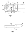
- FIG. 1 is a sectional and side view of a dipped beam 100 known from the state of the art.
- a dipped beam comprises essentially a reflector 101, a light source 102, radiating a power in the form of light signals 103 emitted, disposed at near the top of the reflector 101, and an exit surface 104 of a light beam 106.
- the output surface 104 may be for example a plastic type ice cream; preferably, it does not have properties optical, that is to say that it does not deviate, or very little, the light rays who cross it.
- the light signals 103 Before reaching the exit surface 104, the light signals 103 have to cross, either directly or after reflection on the reflector 101, a lens 105.
- This lens is most often of the type convex and circular. It is called projection lens. She has a input face 110 and an output face 111. It images the light beam 106 whose orientation and scope depend in particular on the provision of the lens 105 within the projector device 100 and features lens optics 105.
- a central portion of the source of light 102 is disposed in the focal zone of a first focus F1 of the reflector 101, and the focus of the projection lens 105 is in the focal zone of a second focus F2 of the reflector 101.
- a signal light 103 emitted by the central portion of the light source 102 will pass by the second focus F2 of the reflector 101 and exit the lens of projection 105 horizontally or approximately horizontally.
- the set of light signals 103 emitted by the party central light source 102 converge to the second focus F2.
- a cache 108 is interposed between the reflector 101 and the projection lens 105.
- the cover 108 is disposed in a plane parallel to the projection lens 105, approximately at the object focal plane of the lens, so that the image of the cache is emitted to infinity. Thanks to the presence of such a cache 108, the light beam 106 that is actually emitted by the device Projector 100 is not sent over a specific break line in the form of an upper portion 109 of the cover 108.
- Figure 2 gives an example of the shape 200 of the light beam 106 projected on a screen.
- a cut-off line 201 marks the border between a low zone where the light intensity is sufficient to illuminate the road and satisfy the different regulations imposed, and a high zone where the light intensity is almost zero.
- the cutoff line 201 presents a change in height 203 at a central axis 202 of the beam.
- the shape 201 shown, with a higher light beam on the part right of the projection corresponds to that of a moving vehicle headlamp in a country where traffic is imposed on the right. In a country where circulation would be imposed on the left, one would obtain a form which, compared to a vertical axis 202, would be symmetrical to that shown.
- a first solution is to provide a hole in the cache 108. If this hole is in the right place, you get a lighted area approximately rectangular above the cut line, this zone containing the portal points. The regulatory requirements are thus satisfied, but the luminous intensity diffused in the rectangle is such that it is unpleasant - even embarrassing - for the driver.
- a second known solution is to slightly roughen the face input of the lens 105.
- a part of the light signals is thus deflected of their initial trajectory and some are emitted towards the points of portico.
- But such a method has several disadvantages: on the one hand the diffuse frosted surface of light almost isotropically, a large amount of energy being wasted, including in areas of the beam where the intensity is already relatively weak; on the other hand, it is necessary to make post treatment of the lens after molding. In practice, we are therefore brought to perform a surfacing operation to obtain a face slightly frosted, this operation succeeding the molding operation.
- the device according to the invention responds to the problems that come to be exposed.
- the device according to the invention proposes a solution that allows to bring a controlled intensity light at the gantry points and in the vicinity of these points, while preserving the presence of a cache so as not to dazzle car drivers crossed and maintaining a good homogeneity of the light beam produced by the projector device to illuminate the road.
- the invention proposes a vehicle projector device automobile, having at least one reflector, a source of light producing a set of light signals that can be reflected by the reflector, an exit lens, having an entrance surface, a exit surface and a focus, to produce a light beam, and a cover disposed between the reflector and the exit lens to form a line in the light beam produced, characterized in that the output lens comprises a set of arrangements made in minus a circumferential portion of the exit surface of the lens, this together being able to deviate in a certain direction a part of light signals encountering this arrangement.
- the deflection directions are directions above the cutoff line.
- these arrangements are able to divert a part light signals encountering this arrangement in one direction corresponding to a portal point.
- this part circumferential is arranged on the lower part of the lens.
- it is substantially symmetrical by relative to a vertical plane of symmetry of the lens.
- this circumferential portion extends over approximately 45 ° on each side of said plane of symmetry.
- This first variant has the advantage of only modifying minimum the external appearance of the lens and therefore be very discreet on the plane visual.
- this part circumferential extends around the entire periphery of the lens.
- This second preferred embodiment has the advantage of do not cause any angular positioning constraints of the lens. But he turns out that the realization of keying arrangement, the type notch on the lens fitting on a rib of its support, is an operation relatively delicate given the fragility of such lenses.
- this circumferential portion is consisting of a frustoconical surface of rectilinear generatrix inclined by a determined angle to get an upward deflection of the optical signals from the focus and crossing it at the low point of the lens.
- this deflection is between 2 and 10 °.
- this circumferential portion is formed of convex ribs disposed on said frustoconical modified surface of the lens.
- said convex ribs are rotated on said frustoconical surface of a rib of dispersion of the light determined to obtain a lateral dispersion of the light at the low point of the lens.
- a lens according to the invention can be designed by simulation and so its manufacturing process is stable. It can even be standardized and used for different projection devices.
- the losses in range and flux in the optical beam are very low of the order of 2%.
- Another object of the invention is a motor vehicle equipped with a projector device including at least one of the features that come to be mentioned.
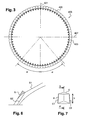
- FIG. 3 shows a projection lens 405 in front view, it is to say as we can see it when we are facing the projector.
- the lens can be circular or elliptical.
- a vertical axis 401 and a horizontal axis 402 intersect at the center of the circle forming the circumference of the lens.
- the output lens 405 here comprises a set of arrangements made around its entire periphery of the exit surface of the lens, this together being able to deviate in a certain direction a part of light signals meeting him.
- the deviation directions are directions above the cut and each corresponding to a portal point
- This preferred embodiment has the advantage of not causing any angular positioning stress of the lens.
- this set of arrangements is arranged on the lower or upper part of the lens.
- this set is symmetrical with respect to a vertical plane of symmetry of the lens containing the vertical axis 401.
- This set is then on a beach angular angle at the center 2 ⁇ , ⁇ being advantageously substantially equal at 45 °.
- This set can therefore also be substantially symmetrical only, or completely asymmetrical.
- This circumferential portion 400 formed of this set of arrangements consists of convex ribs 403 disposed on a frustoconical modified circumferential zone of the lens.
- the circumferential portion 400 ' is disposed on the part of the lens 405 'and is preferably symmetrical with respect to a vertical plane of symmetry of the lens, whose trace in the plane of the figure is the vertical axis 401.
- This circumferential portion extends over an angle ⁇ , of preferably equal to about 45 °, on each side of this plane of symmetry.
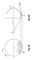
- the outer surface of the lens, as well as its focus F and its axis optical L, are shown in Figure 4B.
- This surface is schematized by the ellipse S1.
- the first step of producing a modified lens according to the invention consists in producing a frustoconical surface of rectilinear generator centered on the optical axis L of the schematized lens by the line S2.
- This surface S2 is defined to obtain a deviation towards the top of the optical signals coming from the focus F crossing it on the low point of The lens.
- this deviation is of angle ⁇ between 2 and 10 °, preferably between 5 and 9 °.
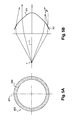
- the circumferential portion 400 is disposed all around the periphery of the exit surface of the lens.
- the external surfaces of the lens S1 and S2 are defined identically to those in the previous figure.
- This second embodiment has the advantage of not causing any angular positioning stress of the lens in the projector.
- any this frustoconical surface S2 are arranged convex ribs.
- Their not is defined so as to get an integer number of ribs on the around the lens and small enough not to interfere with the angular position of the lens.
- this step corresponds to an angle in the center of 1 to 5 °, in view according to Figure 3.
- Their maximum thickness is calculated to divert only the necessary light, for example for a diameter lens equal to 70mm, a thickness of about 3mm.
- Such a rib is shown in perspective in FIG. its plane of symmetry A-A '.
- its height is of the order of 3 to 5mm
- the radius of curvature of its line 12 representative of its convexity, or horizontal radius
- the horizontal radius is determined in such a way known to those skilled in the art to achieve sufficient illumination laterally to the central zone already mentioned, more precisely according to certain standards of 8 ° on each side of the central axis of this zone.
- the vertical radius is determined meanwhile in a manner known to the man of craft to achieve the desired vertical distribution of light.
- the set of convex ribs on the lens is made by rotation on the frustoconical surface S2 of a dispersion rib of the light as previously described with its lateral sides c1 and c2 corresponding to the surface S2 and determined to obtain the dispersion desired light at the low point of the lens.
- the ribs N one of which is here in view section along its plane of symmetry A-A 'are then leveled in the extension of the profile of the surface S1, which is schematized on this figure by removing the hatched portion.
- the sharp-edged slits existing between each rib will be filled with a rounding, to improve the result aesthetic.
- such a lens can be made by molding.
- the only condition for ensuring photometry consistent on the gantry points is that the light reaches the low point of the lens. This is the case for most projector modules elliptical. Otherwise, it is sufficient to provide for an increase in Reflector height to reach the low point of the lens or to design the lens with a smaller diameter so that its low point corresponds to the reflection of the reflector, which leads to a lens of small size and reduced weight, which is particularly interesting.
Landscapes
- Engineering & Computer Science (AREA)
- General Engineering & Computer Science (AREA)
- Non-Portable Lighting Devices Or Systems Thereof (AREA)
- Lighting Device Outwards From Vehicle And Optical Signal (AREA)
Abstract
Description
- des feux de position, d'intensité et de portée faible ;
- des feux de croisement, ou codes, d'intensité plus forte et de portée sur la route avoisinant 70 mètres, qui sont utilisés essentiellement la nuit et dont la répartition du faisceau lumineux est telle qu'elle permet de ne pas éblouir le conducteur d'un véhicule croisé ;
- des feux de route longue portée, et des feux de complément de type longue portée, dont la zone de vision sur la route avoisine 200 mètres, et qui doivent être éteints lorsque l'on croise un autre véhicule afin de ne pas éblouir son conducteur ;
- des feux anti-brouillard.
Claims (12)
- Dispositif projecteur pour véhicule automobile, comportant au moins un réflecteur (101), une source de lumière (102) produisant un ensemble de signaux lumineux (103) pouvant être réfléchis par le réflecteur (101), une lentille de sortie (401), comportant une surface d'entrée (110), une surface de sortie (111) et un foyer (F), pour produire un faisceau lumineux (106), et un cache (108) disposé entre le réflecteur (101) et la lentille de sortie (401) pour réaliser une coupure (201) dans le faisceau lumineux produit (106), caractérisé en ce que la lentille de sortie (401) comporte un ensemble d'aménagements réalisés dans au moins une partie circonférentielle (400, 400') de la surface de sortie de la lentille, cet ensemble étant apte à dévier dans une direction déterminée une partie des signaux lumineux rencontrant cet aménagement (400, 400').
- Dispositif projecteur selon la revendication 1 caractérisé en ce que les directions de déviation sont des directions situées au-dessus de la coupure (201).
- Dispositif projecteur selon l'une des revendications précédentes caractérisé en ce que ces aménagements (400, 400') sont aptes à dévier une partie des signaux lumineux rencontrant ces aménagements dans une direction correspondant à un point de portique.
- Dispositif selon l'une des revendications précédentes, caractérisé en ce que cette partie circonférentielle (400') est disposée sur la partie inférieure de la lentille.
- Dispositif selon la revendication 4, caractérisé en ce que cette partie circonférentielle (400') est sensiblement symétrique par rapport à un plan vertical de symétrie de la lentille.
- Dispositif selon la revendication 5, caractérisé en ce que cette partie circonférentielle (400') s'étend sur environ 45° de chaque côté de dudit plan de symétrie.
- Dispositif selon l'une des revendications 1 à 3, caractérisé en ce que cette partie circonférentielle (400) s'étend sur tout le pourtour de la lentille (405).
- Dispositif selon l'une des revendications précédentes, caractérisé en ce que cette partie circonférentielle (400) est constituée d'une surface tronconique (S2) de génératrice rectiligne inclinée d'un angle déterminé pour obtenir une déviation (β) vers le haut des signaux optiques issus du foyer (F) et la traversant au point bas de la lentille.
- Dispositif selon la revendication 8, caractérisé en ce que ladite déviation (β) est comprise entre 2 et 10°.
- Dispositif selon la revendication 7 ou 8, caractérisé en ce que cette partie circonférentielle (400) est formée de nervures convexes (403) disposées sur ladite surface modifiée tronconique (S2) de la lentille.
- Dispositif selon la revendication 10, caractérisé en ce que lesdites nervures convexes sont réalisées par rotation sur ladite surface tronconique (S2) d'une nervure de dispersion de la lumière déterminée pour obtenir une dispersion latérale de la lumière au point bas de la lentille.
- Véhicule automobile équipé d'un dispositif projecteur selon l'une des revendications précédentes.
Priority Applications (1)
| Application Number | Priority Date | Filing Date | Title |
|---|---|---|---|
| PL04290793T PL1464890T3 (pl) | 2003-04-03 | 2004-03-23 | Urządzenie reflektorowe dla samochodu oświetlające punkty ramy drogowskazowej |
Applications Claiming Priority (2)
| Application Number | Priority Date | Filing Date | Title |
|---|---|---|---|
| FR0304159 | 2003-04-03 | ||
| FR0304159A FR2853394B1 (fr) | 2003-04-03 | 2003-04-03 | Dispositif de projection pour vehicule automobile eclairant des points de portique |
Publications (2)
| Publication Number | Publication Date |
|---|---|
| EP1464890A1 true EP1464890A1 (fr) | 2004-10-06 |
| EP1464890B1 EP1464890B1 (fr) | 2006-08-23 |
Family
ID=32843136
Family Applications (1)
| Application Number | Title | Priority Date | Filing Date |
|---|---|---|---|
| EP04290793A Expired - Lifetime EP1464890B1 (fr) | 2003-04-03 | 2004-03-23 | Dispositif de projecteur pour véhicule automobile éclairant des points de portique |
Country Status (7)
| Country | Link |
|---|---|
| US (1) | US7040789B2 (fr) |
| EP (1) | EP1464890B1 (fr) |
| AT (1) | ATE337519T1 (fr) |
| DE (1) | DE602004002016T2 (fr) |
| ES (1) | ES2271797T3 (fr) |
| FR (1) | FR2853394B1 (fr) |
| PL (1) | PL1464890T3 (fr) |
Cited By (2)
| Publication number | Priority date | Publication date | Assignee | Title |
|---|---|---|---|---|
| FR2883629A1 (fr) * | 2005-03-22 | 2006-09-29 | Valeo Vision Sa | Lentille pour module optique de dispositif d'eclairage pour vehicule automobile |
| DE102013207850A1 (de) | 2013-04-29 | 2014-10-30 | Automotive Lighting Reutlingen Gmbh | Lichtmodul für einen Kraftfahrzeugscheinwerfer |
Families Citing this family (3)
| Publication number | Priority date | Publication date | Assignee | Title |
|---|---|---|---|---|
| FR2925656B1 (fr) * | 2007-12-21 | 2013-08-23 | Holophane | Lentille de module d'eclairage de vehicule automobile |
| US9151469B2 (en) | 2010-04-09 | 2015-10-06 | Koninklijke Philips N.V. | Lighting device having a smooth cut-off |
| DE102011114636A1 (de) | 2011-10-04 | 2013-04-04 | Automotive Lighting Reutlingen Gmbh | Anordnung und Dimensionierung von Overhead-Elementen auf einer Projektionslinse eines Kraftfahrzeugscheinwerfers |
Citations (3)
| Publication number | Priority date | Publication date | Assignee | Title |
|---|---|---|---|---|
| US3708221A (en) * | 1970-04-02 | 1973-01-02 | Anchor Hocking Corp | Aspheric lens and method of manufacture |
| US5014173A (en) * | 1985-11-07 | 1991-05-07 | Robert Bosch Gmbh | Low beam or fog headlamp for motor vehicles |
| DE9000395U1 (de) * | 1990-01-16 | 1991-05-16 | Robert Bosch Gmbh, 7000 Stuttgart | Scheinwerfer für Kraftfahrzeuge |
Family Cites Families (3)
| Publication number | Priority date | Publication date | Assignee | Title |
|---|---|---|---|---|
| US4902508A (en) * | 1988-07-11 | 1990-02-20 | Purdue Research Foundation | Tissue graft composition |
| US5307247A (en) * | 1992-09-22 | 1994-04-26 | Autopal, Statni Podnik | Headlamp for motor vehicles |
| JP3886672B2 (ja) * | 1999-07-12 | 2007-02-28 | 株式会社小糸製作所 | 車両用前照灯 |
-
2003
- 2003-04-03 FR FR0304159A patent/FR2853394B1/fr not_active Expired - Lifetime
-
2004
- 2004-03-23 DE DE602004002016T patent/DE602004002016T2/de not_active Expired - Lifetime
- 2004-03-23 PL PL04290793T patent/PL1464890T3/pl unknown
- 2004-03-23 EP EP04290793A patent/EP1464890B1/fr not_active Expired - Lifetime
- 2004-03-23 ES ES04290793T patent/ES2271797T3/es not_active Expired - Lifetime
- 2004-03-23 AT AT04290793T patent/ATE337519T1/de not_active IP Right Cessation
- 2004-03-31 US US10/815,502 patent/US7040789B2/en not_active Expired - Fee Related
Patent Citations (3)
| Publication number | Priority date | Publication date | Assignee | Title |
|---|---|---|---|---|
| US3708221A (en) * | 1970-04-02 | 1973-01-02 | Anchor Hocking Corp | Aspheric lens and method of manufacture |
| US5014173A (en) * | 1985-11-07 | 1991-05-07 | Robert Bosch Gmbh | Low beam or fog headlamp for motor vehicles |
| DE9000395U1 (de) * | 1990-01-16 | 1991-05-16 | Robert Bosch Gmbh, 7000 Stuttgart | Scheinwerfer für Kraftfahrzeuge |
Cited By (5)
| Publication number | Priority date | Publication date | Assignee | Title |
|---|---|---|---|---|
| FR2883629A1 (fr) * | 2005-03-22 | 2006-09-29 | Valeo Vision Sa | Lentille pour module optique de dispositif d'eclairage pour vehicule automobile |
| US7583451B2 (en) | 2005-03-22 | 2009-09-01 | Valeo Vision | Lens for an optical module of a lighting apparatus for a motor vehicle |
| DE102013207850A1 (de) | 2013-04-29 | 2014-10-30 | Automotive Lighting Reutlingen Gmbh | Lichtmodul für einen Kraftfahrzeugscheinwerfer |
| EP2799761A2 (fr) | 2013-04-29 | 2014-11-05 | Automotive Lighting Reutlingen GmbH | Module d'éclairage de phare de véhicule automobile |
| US9249943B2 (en) | 2013-04-29 | 2016-02-02 | Automotive Lighting Reutlingen Gmbh | Light module for a motor vehicle headlamp |
Also Published As
| Publication number | Publication date |
|---|---|
| US7040789B2 (en) | 2006-05-09 |
| ATE337519T1 (de) | 2006-09-15 |
| US20040196662A1 (en) | 2004-10-07 |
| EP1464890B1 (fr) | 2006-08-23 |
| FR2853394A1 (fr) | 2004-10-08 |
| DE602004002016T2 (de) | 2007-04-12 |
| ES2271797T3 (es) | 2007-04-16 |
| DE602004002016D1 (de) | 2006-10-05 |
| FR2853394B1 (fr) | 2006-03-10 |
| PL1464890T3 (pl) | 2006-12-29 |
Similar Documents
| Publication | Publication Date | Title |
|---|---|---|
| EP3147557B1 (fr) | Element optique primaire pour module lumineux de vehicule automobile | |
| EP3521691B1 (fr) | Module lumineux pour véhicule automobile, et dispositif d'éclairage et/ou de signalisation muni d'un tel module | |
| EP3067618B1 (fr) | Dispositif lumineux a guides optiques | |
| EP3350019B1 (fr) | Système d'éclairage pour véhicules automobiles | |
| WO2020025171A1 (fr) | Module lumineux imageant la surface eclairee d'un collecteur | |
| FR2858042A1 (fr) | Module d'eclairage elliptique sans cache realisant un faisceau d'eclairage a coupure et projecteur comportant un tel module | |
| FR2973476A1 (fr) | Systeme optique pour generer un faisceau lumineux composite de large ouverture angulaire | |
| FR2942294A1 (fr) | Module de lampe pour un dispositif d'eclairage | |
| EP2792938A2 (fr) | Module optique et dispositif d'éclairage et/ou de signalisation pour véhicule automobile | |
| EP0250313B1 (fr) | Projecteur additionnel à un projecteur de croisement pour véhicule automobile | |
| WO2016124718A1 (fr) | Module lumineux d'un véhicule compatible au trafic gauche et au trafic droit | |
| EP1870633A1 (fr) | Module de projecteur avec diode électroluminescente | |
| EP2846081B1 (fr) | Dispositif d'éclairage et de signalisation d'un véhicule | |
| EP3453946A1 (fr) | Module lumineux pour véhicule automobile, et dispositif d'éclairage et/ou de signalisation muni d'un tel module | |
| EP3030830A1 (fr) | Dispositif d'eclairage et/ou de signalisation pour vehicules automobiles | |
| FR2828153A1 (fr) | Lampe de vehicule a marque indicatrice | |
| EP1464890B1 (fr) | Dispositif de projecteur pour véhicule automobile éclairant des points de portique | |
| FR2841512A1 (fr) | Dispositif projecteur pour vehicule automobile eclairant des points de portique | |
| EP0581661A1 (fr) | Procédé de fabrication d'un miroir pour dispositif d'éclairage ou de signalisation de véhicule et projecteur équipé d'un nouveau miroir | |
| FR2760070A1 (fr) | Projecteur comportant une lampe a deux filaments pour engendrer un faisceau coupe et un faisceau non coupe | |
| EP1400748A1 (fr) | Dispositif projecteur de véhicule automobile à miroir et élément de déviation conjugués avec coupure non plate | |
| EP1422470B1 (fr) | Dispositif projecteur pour véhicule automobile avec plage éclairante élargie | |
| EP4433327A1 (fr) | Module lumineux avec fonctions d'éclairage et de signalisation | |
| EP0635674A1 (fr) | Feu de signalisation à voyant et écran intermédiaire pour véhicule automobile | |
| FR3042844A1 (fr) | Systeme d'eclairage pour vehicules automobiles |
Legal Events
| Date | Code | Title | Description |
|---|---|---|---|
| PUAI | Public reference made under article 153(3) epc to a published international application that has entered the european phase |
Free format text: ORIGINAL CODE: 0009012 |
|
| AK | Designated contracting states |
Kind code of ref document: A1 Designated state(s): AT BE BG CH CY CZ DE DK EE ES FI FR GB GR HU IE IT LI LU MC NL PL PT RO SE SI SK TR |
|
| AX | Request for extension of the european patent |
Extension state: AL HR LT LV MK |
|
| 17P | Request for examination filed |
Effective date: 20050318 |
|
| AKX | Designation fees paid |
Designated state(s): AT BE BG CH CY CZ DE DK EE ES FI FR GB GR HU IE IT LI LU MC NL PL PT RO SE SI SK TR |
|
| GRAP | Despatch of communication of intention to grant a patent |
Free format text: ORIGINAL CODE: EPIDOSNIGR1 |
|
| GRAS | Grant fee paid |
Free format text: ORIGINAL CODE: EPIDOSNIGR3 |
|
| GRAA | (expected) grant |
Free format text: ORIGINAL CODE: 0009210 |
|
| AK | Designated contracting states |
Kind code of ref document: B1 Designated state(s): AT BE BG CH CY CZ DE DK EE ES FI FR GB GR HU IE IT LI LU MC NL PL PT RO SE SI SK TR |
|
| PG25 | Lapsed in a contracting state [announced via postgrant information from national office to epo] |
Ref country code: SI Free format text: LAPSE BECAUSE OF FAILURE TO SUBMIT A TRANSLATION OF THE DESCRIPTION OR TO PAY THE FEE WITHIN THE PRESCRIBED TIME-LIMIT Effective date: 20060823 Ref country code: NL Free format text: LAPSE BECAUSE OF FAILURE TO SUBMIT A TRANSLATION OF THE DESCRIPTION OR TO PAY THE FEE WITHIN THE PRESCRIBED TIME-LIMIT Effective date: 20060823 Ref country code: IE Free format text: LAPSE BECAUSE OF FAILURE TO SUBMIT A TRANSLATION OF THE DESCRIPTION OR TO PAY THE FEE WITHIN THE PRESCRIBED TIME-LIMIT Effective date: 20060823 Ref country code: GB Free format text: LAPSE BECAUSE OF FAILURE TO SUBMIT A TRANSLATION OF THE DESCRIPTION OR TO PAY THE FEE WITHIN THE PRESCRIBED TIME-LIMIT Effective date: 20060823 Ref country code: RO Free format text: LAPSE BECAUSE OF FAILURE TO SUBMIT A TRANSLATION OF THE DESCRIPTION OR TO PAY THE FEE WITHIN THE PRESCRIBED TIME-LIMIT Effective date: 20060823 Ref country code: AT Free format text: LAPSE BECAUSE OF FAILURE TO SUBMIT A TRANSLATION OF THE DESCRIPTION OR TO PAY THE FEE WITHIN THE PRESCRIBED TIME-LIMIT Effective date: 20060823 Ref country code: FI Free format text: LAPSE BECAUSE OF FAILURE TO SUBMIT A TRANSLATION OF THE DESCRIPTION OR TO PAY THE FEE WITHIN THE PRESCRIBED TIME-LIMIT Effective date: 20060823 Ref country code: IT Free format text: LAPSE BECAUSE OF FAILURE TO SUBMIT A TRANSLATION OF THE DESCRIPTION OR TO PAY THE FEE WITHIN THE PRESCRIBED TIME-LIMIT;WARNING: LAPSES OF ITALIAN PATENTS WITH EFFECTIVE DATE BEFORE 2007 MAY HAVE OCCURRED AT ANY TIME BEFORE 2007. THE CORRECT EFFECTIVE DATE MAY BE DIFFERENT FROM THE ONE RECORDED. Effective date: 20060823 |
|
| REG | Reference to a national code |
Ref country code: GB Ref legal event code: FG4D Free format text: NOT ENGLISH |
|
| REG | Reference to a national code |
Ref country code: CH Ref legal event code: EP |
|
| REG | Reference to a national code |
Ref country code: IE Ref legal event code: FG4D Free format text: LANGUAGE OF EP DOCUMENT: FRENCH |
|
| REF | Corresponds to: |
Ref document number: 602004002016 Country of ref document: DE Date of ref document: 20061005 Kind code of ref document: P |
|
| PG25 | Lapsed in a contracting state [announced via postgrant information from national office to epo] |
Ref country code: DK Free format text: LAPSE BECAUSE OF FAILURE TO SUBMIT A TRANSLATION OF THE DESCRIPTION OR TO PAY THE FEE WITHIN THE PRESCRIBED TIME-LIMIT Effective date: 20061123 Ref country code: BG Free format text: LAPSE BECAUSE OF FAILURE TO SUBMIT A TRANSLATION OF THE DESCRIPTION OR TO PAY THE FEE WITHIN THE PRESCRIBED TIME-LIMIT Effective date: 20061123 Ref country code: SE Free format text: LAPSE BECAUSE OF FAILURE TO SUBMIT A TRANSLATION OF THE DESCRIPTION OR TO PAY THE FEE WITHIN THE PRESCRIBED TIME-LIMIT Effective date: 20061123 |
|
| PG25 | Lapsed in a contracting state [announced via postgrant information from national office to epo] |
Ref country code: PT Free format text: LAPSE BECAUSE OF FAILURE TO SUBMIT A TRANSLATION OF THE DESCRIPTION OR TO PAY THE FEE WITHIN THE PRESCRIBED TIME-LIMIT Effective date: 20070125 |
|
| NLV1 | Nl: lapsed or annulled due to failure to fulfill the requirements of art. 29p and 29m of the patents act | ||
| GBV | Gb: ep patent (uk) treated as always having been void in accordance with gb section 77(7)/1977 [no translation filed] |
Effective date: 20060823 |
|
| REG | Reference to a national code |
Ref country code: IE Ref legal event code: FD4D |
|
| REG | Reference to a national code |
Ref country code: ES Ref legal event code: FG2A Ref document number: 2271797 Country of ref document: ES Kind code of ref document: T3 |
|
| PLBE | No opposition filed within time limit |
Free format text: ORIGINAL CODE: 0009261 |
|
| STAA | Information on the status of an ep patent application or granted ep patent |
Free format text: STATUS: NO OPPOSITION FILED WITHIN TIME LIMIT |
|
| 26N | No opposition filed |
Effective date: 20070524 |
|
| BERE | Be: lapsed |
Owner name: VALEO VISION Effective date: 20070331 |
|
| PG25 | Lapsed in a contracting state [announced via postgrant information from national office to epo] |
Ref country code: BE Free format text: LAPSE BECAUSE OF NON-PAYMENT OF DUE FEES Effective date: 20070331 |
|
| PG25 | Lapsed in a contracting state [announced via postgrant information from national office to epo] |
Ref country code: MC Free format text: LAPSE BECAUSE OF NON-PAYMENT OF DUE FEES Effective date: 20070331 |
|
| PG25 | Lapsed in a contracting state [announced via postgrant information from national office to epo] |
Ref country code: GR Free format text: LAPSE BECAUSE OF FAILURE TO SUBMIT A TRANSLATION OF THE DESCRIPTION OR TO PAY THE FEE WITHIN THE PRESCRIBED TIME-LIMIT Effective date: 20061124 |
|
| PG25 | Lapsed in a contracting state [announced via postgrant information from national office to epo] |
Ref country code: EE Free format text: LAPSE BECAUSE OF FAILURE TO SUBMIT A TRANSLATION OF THE DESCRIPTION OR TO PAY THE FEE WITHIN THE PRESCRIBED TIME-LIMIT Effective date: 20060823 |
|
| PGRI | Patent reinstated in contracting state [announced from national office to epo] |
Ref country code: IT Effective date: 20080601 |
|
| REG | Reference to a national code |
Ref country code: CH Ref legal event code: PL |
|
| PG25 | Lapsed in a contracting state [announced via postgrant information from national office to epo] |
Ref country code: LI Free format text: LAPSE BECAUSE OF NON-PAYMENT OF DUE FEES Effective date: 20080331 Ref country code: CH Free format text: LAPSE BECAUSE OF NON-PAYMENT OF DUE FEES Effective date: 20080331 |
|
| PG25 | Lapsed in a contracting state [announced via postgrant information from national office to epo] |
Ref country code: CY Free format text: LAPSE BECAUSE OF FAILURE TO SUBMIT A TRANSLATION OF THE DESCRIPTION OR TO PAY THE FEE WITHIN THE PRESCRIBED TIME-LIMIT Effective date: 20060823 Ref country code: LU Free format text: LAPSE BECAUSE OF NON-PAYMENT OF DUE FEES Effective date: 20070323 |
|
| PG25 | Lapsed in a contracting state [announced via postgrant information from national office to epo] |
Ref country code: TR Free format text: LAPSE BECAUSE OF FAILURE TO SUBMIT A TRANSLATION OF THE DESCRIPTION OR TO PAY THE FEE WITHIN THE PRESCRIBED TIME-LIMIT Effective date: 20060823 Ref country code: HU Free format text: LAPSE BECAUSE OF FAILURE TO SUBMIT A TRANSLATION OF THE DESCRIPTION OR TO PAY THE FEE WITHIN THE PRESCRIBED TIME-LIMIT Effective date: 20070224 |
|
| REG | Reference to a national code |
Ref country code: FR Ref legal event code: PLFP Year of fee payment: 13 |
|
| REG | Reference to a national code |
Ref country code: FR Ref legal event code: PLFP Year of fee payment: 14 |
|
| PGFP | Annual fee paid to national office [announced via postgrant information from national office to epo] |
Ref country code: DE Payment date: 20170316 Year of fee payment: 14 Ref country code: FR Payment date: 20170331 Year of fee payment: 14 |
|
| PGFP | Annual fee paid to national office [announced via postgrant information from national office to epo] |
Ref country code: PL Payment date: 20170220 Year of fee payment: 14 Ref country code: CZ Payment date: 20170222 Year of fee payment: 14 Ref country code: SK Payment date: 20170221 Year of fee payment: 14 |
|
| PGFP | Annual fee paid to national office [announced via postgrant information from national office to epo] |
Ref country code: IT Payment date: 20170315 Year of fee payment: 14 |
|
| PGFP | Annual fee paid to national office [announced via postgrant information from national office to epo] |
Ref country code: ES Payment date: 20170331 Year of fee payment: 14 |
|
| REG | Reference to a national code |
Ref country code: DE Ref legal event code: R119 Ref document number: 602004002016 Country of ref document: DE |
|
| PG25 | Lapsed in a contracting state [announced via postgrant information from national office to epo] |
Ref country code: CZ Free format text: LAPSE BECAUSE OF NON-PAYMENT OF DUE FEES Effective date: 20180323 |
|
| REG | Reference to a national code |
Ref country code: SK Ref legal event code: MM4A Ref document number: E 1272 Country of ref document: SK Effective date: 20180323 |
|
| PG25 | Lapsed in a contracting state [announced via postgrant information from national office to epo] |
Ref country code: DE Free format text: LAPSE BECAUSE OF NON-PAYMENT OF DUE FEES Effective date: 20181002 Ref country code: SK Free format text: LAPSE BECAUSE OF NON-PAYMENT OF DUE FEES Effective date: 20180323 |
|
| PG25 | Lapsed in a contracting state [announced via postgrant information from national office to epo] |
Ref country code: IT Free format text: LAPSE BECAUSE OF FAILURE TO SUBMIT A TRANSLATION OF THE DESCRIPTION OR TO PAY THE FEE WITHIN THE PRESCRIBED TIME-LIMIT Effective date: 20180323 |
|
| PG25 | Lapsed in a contracting state [announced via postgrant information from national office to epo] |
Ref country code: FR Free format text: LAPSE BECAUSE OF NON-PAYMENT OF DUE FEES Effective date: 20180331 |
|
| PG25 | Lapsed in a contracting state [announced via postgrant information from national office to epo] |
Ref country code: PL Free format text: LAPSE BECAUSE OF NON-PAYMENT OF DUE FEES Effective date: 20180323 |
|
| REG | Reference to a national code |
Ref country code: ES Ref legal event code: FD2A Effective date: 20190911 |
|
| PG25 | Lapsed in a contracting state [announced via postgrant information from national office to epo] |
Ref country code: ES Free format text: LAPSE BECAUSE OF NON-PAYMENT OF DUE FEES Effective date: 20180324 |