EP2798205B1 - Turbomachine - Google Patents
Turbomachine Download PDFInfo
- Publication number
- EP2798205B1 EP2798205B1 EP12812276.9A EP12812276A EP2798205B1 EP 2798205 B1 EP2798205 B1 EP 2798205B1 EP 12812276 A EP12812276 A EP 12812276A EP 2798205 B1 EP2798205 B1 EP 2798205B1
- Authority
- EP
- European Patent Office
- Prior art keywords
- rotor
- rotor blades
- operating mode
- sections
- cyclically
- Prior art date
- Legal status (The legal status is an assumption and is not a legal conclusion. Google has not performed a legal analysis and makes no representation as to the accuracy of the status listed.)
- Active
Links
- 238000000034 method Methods 0.000 claims description 10
- 125000004122 cyclic group Chemical group 0.000 claims description 6
- 238000011144 upstream manufacturing Methods 0.000 claims description 2
- 238000010438 heat treatment Methods 0.000 claims 2
- 239000012466 permeate Substances 0.000 claims 1
- XLYOFNOQVPJJNP-UHFFFAOYSA-N water Substances O XLYOFNOQVPJJNP-UHFFFAOYSA-N 0.000 description 12
- 238000010276 construction Methods 0.000 description 7
- 230000008878 coupling Effects 0.000 description 5
- 238000010168 coupling process Methods 0.000 description 5
- 238000005859 coupling reaction Methods 0.000 description 5
- 230000033001 locomotion Effects 0.000 description 5
- 230000001681 protective effect Effects 0.000 description 4
- 238000006073 displacement reaction Methods 0.000 description 3
- 230000007935 neutral effect Effects 0.000 description 3
- 238000009826 distribution Methods 0.000 description 2
- 230000000694 effects Effects 0.000 description 2
- 230000010354 integration Effects 0.000 description 2
- 238000004519 manufacturing process Methods 0.000 description 2
- 238000010248 power generation Methods 0.000 description 2
- 230000001133 acceleration Effects 0.000 description 1
- 238000005457 optimization Methods 0.000 description 1
- 230000002093 peripheral effect Effects 0.000 description 1
- 230000002787 reinforcement Effects 0.000 description 1
- 239000000779 smoke Substances 0.000 description 1
- 239000003643 water by type Substances 0.000 description 1
Images


Classifications
-
- F—MECHANICAL ENGINEERING; LIGHTING; HEATING; WEAPONS; BLASTING
- F03—MACHINES OR ENGINES FOR LIQUIDS; WIND, SPRING, OR WEIGHT MOTORS; PRODUCING MECHANICAL POWER OR A REACTIVE PROPULSIVE THRUST, NOT OTHERWISE PROVIDED FOR
- F03D—WIND MOTORS
- F03D3/00—Wind motors with rotation axis substantially perpendicular to the air flow entering the rotor
- F03D3/06—Rotors
- F03D3/062—Rotors characterised by their construction elements
- F03D3/066—Rotors characterised by their construction elements the wind engaging parts being movable relative to the rotor
- F03D3/067—Cyclic movements
- F03D3/068—Cyclic movements mechanically controlled by the rotor structure
-
- F—MECHANICAL ENGINEERING; LIGHTING; HEATING; WEAPONS; BLASTING
- F03—MACHINES OR ENGINES FOR LIQUIDS; WIND, SPRING, OR WEIGHT MOTORS; PRODUCING MECHANICAL POWER OR A REACTIVE PROPULSIVE THRUST, NOT OTHERWISE PROVIDED FOR
- F03B—MACHINES OR ENGINES FOR LIQUIDS
- F03B17/00—Other machines or engines
- F03B17/06—Other machines or engines using liquid flow with predominantly kinetic energy conversion, e.g. of swinging-flap type, "run-of-river", "ultra-low head"
- F03B17/062—Other machines or engines using liquid flow with predominantly kinetic energy conversion, e.g. of swinging-flap type, "run-of-river", "ultra-low head" with rotation axis substantially at right angle to flow direction
- F03B17/065—Other machines or engines using liquid flow with predominantly kinetic energy conversion, e.g. of swinging-flap type, "run-of-river", "ultra-low head" with rotation axis substantially at right angle to flow direction the flow engaging parts having a cyclic movement relative to the rotor during its rotation
- F03B17/067—Other machines or engines using liquid flow with predominantly kinetic energy conversion, e.g. of swinging-flap type, "run-of-river", "ultra-low head" with rotation axis substantially at right angle to flow direction the flow engaging parts having a cyclic movement relative to the rotor during its rotation the cyclic relative movement being positively coupled to the movement of rotation
-
- F—MECHANICAL ENGINEERING; LIGHTING; HEATING; WEAPONS; BLASTING
- F03—MACHINES OR ENGINES FOR LIQUIDS; WIND, SPRING, OR WEIGHT MOTORS; PRODUCING MECHANICAL POWER OR A REACTIVE PROPULSIVE THRUST, NOT OTHERWISE PROVIDED FOR
- F03D—WIND MOTORS
- F03D7/00—Controlling wind motors
- F03D7/06—Controlling wind motors the wind motors having rotation axis substantially perpendicular to the air flow entering the rotor
-
- F—MECHANICAL ENGINEERING; LIGHTING; HEATING; WEAPONS; BLASTING
- F05—INDEXING SCHEMES RELATING TO ENGINES OR PUMPS IN VARIOUS SUBCLASSES OF CLASSES F01-F04
- F05B—INDEXING SCHEME RELATING TO WIND, SPRING, WEIGHT, INERTIA OR LIKE MOTORS, TO MACHINES OR ENGINES FOR LIQUIDS COVERED BY SUBCLASSES F03B, F03D AND F03G
- F05B2260/00—Function
- F05B2260/70—Adjusting of angle of incidence or attack of rotating blades
- F05B2260/72—Adjusting of angle of incidence or attack of rotating blades by turning around an axis parallel to the rotor centre line
-
- F—MECHANICAL ENGINEERING; LIGHTING; HEATING; WEAPONS; BLASTING
- F05—INDEXING SCHEMES RELATING TO ENGINES OR PUMPS IN VARIOUS SUBCLASSES OF CLASSES F01-F04
- F05B—INDEXING SCHEME RELATING TO WIND, SPRING, WEIGHT, INERTIA OR LIKE MOTORS, TO MACHINES OR ENGINES FOR LIQUIDS COVERED BY SUBCLASSES F03B, F03D AND F03G
- F05B2260/00—Function
- F05B2260/70—Adjusting of angle of incidence or attack of rotating blades
- F05B2260/77—Adjusting of angle of incidence or attack of rotating blades the adjusting mechanism driven or triggered by centrifugal forces
-
- F—MECHANICAL ENGINEERING; LIGHTING; HEATING; WEAPONS; BLASTING
- F05—INDEXING SCHEMES RELATING TO ENGINES OR PUMPS IN VARIOUS SUBCLASSES OF CLASSES F01-F04
- F05B—INDEXING SCHEME RELATING TO WIND, SPRING, WEIGHT, INERTIA OR LIKE MOTORS, TO MACHINES OR ENGINES FOR LIQUIDS COVERED BY SUBCLASSES F03B, F03D AND F03G
- F05B2270/00—Control
- F05B2270/30—Control parameters, e.g. input parameters
- F05B2270/321—Wind directions
-
- Y—GENERAL TAGGING OF NEW TECHNOLOGICAL DEVELOPMENTS; GENERAL TAGGING OF CROSS-SECTIONAL TECHNOLOGIES SPANNING OVER SEVERAL SECTIONS OF THE IPC; TECHNICAL SUBJECTS COVERED BY FORMER USPC CROSS-REFERENCE ART COLLECTIONS [XRACs] AND DIGESTS
- Y02—TECHNOLOGIES OR APPLICATIONS FOR MITIGATION OR ADAPTATION AGAINST CLIMATE CHANGE
- Y02E—REDUCTION OF GREENHOUSE GAS [GHG] EMISSIONS, RELATED TO ENERGY GENERATION, TRANSMISSION OR DISTRIBUTION
- Y02E10/00—Energy generation through renewable energy sources
- Y02E10/20—Hydro energy
-
- Y—GENERAL TAGGING OF NEW TECHNOLOGICAL DEVELOPMENTS; GENERAL TAGGING OF CROSS-SECTIONAL TECHNOLOGIES SPANNING OVER SEVERAL SECTIONS OF THE IPC; TECHNICAL SUBJECTS COVERED BY FORMER USPC CROSS-REFERENCE ART COLLECTIONS [XRACs] AND DIGESTS
- Y02—TECHNOLOGIES OR APPLICATIONS FOR MITIGATION OR ADAPTATION AGAINST CLIMATE CHANGE
- Y02E—REDUCTION OF GREENHOUSE GAS [GHG] EMISSIONS, RELATED TO ENERGY GENERATION, TRANSMISSION OR DISTRIBUTION
- Y02E10/00—Energy generation through renewable energy sources
- Y02E10/70—Wind energy
- Y02E10/74—Wind turbines with rotation axis perpendicular to the wind direction
Definitions
- the subject invention relates to an alternative device for using the wind or water energy based on a Cyclogyro rotor, preferably designed as a small power plant, with increased efficiency and extended range of applications.
- the invention relates to a turbomachine, having a substantially cylindrical rotor with a rotor body and a rotation axis, wherein the rotor is adapted to be traversed in a direction perpendicular to the axis of rotation, with a plurality of parallel to the axis of rotation in the rotor body arranged rotor blades and with a Adjustment device for the cyclical adjustment of the rotor blades
- Wind turbines are either built as large wind farms, which in addition to the high construction costs high costs in the power grid infrastructure are required, or as decentralized small plants whose construction costs and infrastructure expenses - relatively speaking - lower. Wind as an energy source is available in Europe for about 4,000 hours per year, with the wind speed extending over a wide range, which can be approximately described by a Weibull distribution, with a maximum frequency in the range of about 2 to 8 m / sec ..
- EP 1 422 422 A2 (Takahashi, 2002 ) is a wind turbine based on a Darrieus rotor known, the rigid rotor blades are designed with a wing profile, which are pocket-shaped and open on one side, to increase the wind yield at low wind speeds.
- the US 6,379,115 B discloses a turbomachine having the features of the preamble of claim 1.
- the object of the present invention is to significantly expand the range of exploitable flow rates with a novel turbine design, to increase the efficiency at low flow velocities and to increase overall the energy yield.
- this object is achieved by a device of the type mentioned by the features of the characterizing part of claim 1.
- a special rotor based on the principle of a Cyclogyro rotor is used to generate energy from an air or water flow, the rotor blades may have two different wing shapes depending on the flow velocity.
- the rotor blades are pivotally arranged along a rotation axis about a cyclic angle of attack.
- This swivel angle is usually up to +/- 45 °, preferably up to +/- 35 °.
- the rotor blades are cyclically moved by the swivel angle from the negative to the positive maximum value, where there is twice a neutral swivel angle and once each a maximum positive and maximum negative swivel angle.
- Via an integrated offset control is influenced in which rotational position to the flow direction, a neutral tilt angle or a max. Negative or positive tilt angle is present. A maximum energy yield can be obtained if the neutral Swivel angle as parallel as possible to the flow direction and the max.
- the rotor blades are preferably a fully symmetrical profile, which can be unfolded along the axis of symmetry from the trailing edge to the profile nose. This results in two profile half-body, which generate a high flow resistance with appropriate flow.
- the returning rotor blade is closed and offers only a very low flow resistance. In this way, the moving in the direction of flow rotor blade is opened and generates a high flow resistance, and the returning against the flow direction of the rotor blade is closed and provides only a very low flow resistance.
- the rotor blade thus becomes a resistance rotor at low to medium flow rates. At higher flow velocities, the rotor blades remain closed and the rotor becomes a buoyancy rotor.
- the pivotable portions of a first position are compact to each other and form the wing profile described above.
- the two sections are unfolded, so that the cross-section, which is exposed to the flow, is multiplied.
- the two sections thereby form a blade in the manner of a two-dimensional Pelltonschaufel, that is, that the cross section corresponds approximately to a portion of a cardioid. This optimizes the flow behavior in displacement operation.
- the pivot angle of the two sections from the compact position to the blade-like position is typically between 135 ° and 180 °, but should be at least 90 °. Preferably, this pivot angle is divided approximately evenly on the two sections.
- the turbomachine according to the invention can be represented in an advantageous manner as part of a hydroelectric power plant, in which the rotor is arranged exposed at the bottom of a flowing body of water. At most, a grid is provided around the rotor, which prevents damage by collision with Schwemmgut. However, it is also possible to cover the rotor at least partially upwards.
- the turbomachine can also be designed as part of a wind power plant, wherein preferably the arrangement is provided on a building roof.
- a diffuser upstream of the rotor and a diffuser downstream of the rotor may be provided.
- the integration of the wind turbine offers in the roof construction of a building, eg. B. in the gable, to.
- the inclined roof surface and the building wall of an average single-family home can increase the flow rate of the air flow by a factor of 1.25 to 2 depending on the geometric conditions, resulting in an increase of the energy yield by a factor of 1.95 to 8.
- An arrangement of the wind turbine on buildings, preferably in the region of the roof edges of buildings or on flat roofs of high or larger commercial buildings also allows significant accelerations of the flow rate and an increase in the energy yield of such wind turbines.
- the energy yield at low flow velocities such as these z. B. prevail in running waters without backlog, on the one hand by the use of rotor blades with a "morphing wing" design, achieved and on the other hand by a targeted increase in the local flow velocity by means of a fluidically trained device.
- This preferably consists of a funnel-shaped narrowing inlet area, which causes an increase in the flow velocity, and a rapidly widening outlet area, causing a pressure reduction in the mass flow at the exit from the rotor.
- the invention relates to a method for operating a turbomachine of the type described above.
- a method for operating a turbomachine of the type described above provides that a rotor is flowed transversely to its axis of rotation, wherein the rotor blades are cyclically adjusted during rotation.
- this adjustment should be made at least partially by cyclic opening / closing of two sections forming the rotor blades.
- This method can be carried out in two different embodiments.
- a first preferred embodiment variant of this method is switched depending on the flow velocity between two operating modes. At low flow velocity, the cyclic opening / closing of the sections forming the rotor blades takes place. At higher flow velocities, in a second operating mode, the cyclical adjustment of the rotor blades is maintained by a pivoting movement, in which, however, the profile as such remains. But it is also possible to perform the adjustment centrifugally controlled in dependence on the rotor speed.
- a pivoting movement of the rotor blades can be performed simultaneously with the opening / closing.
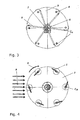
- Fig. 1 shows a cyclogyro rotor of the subject type in an isometric view
- Fig. 2 and Fig. 3 show the cyclogyro rotor in view and side view
- Fig. 4 shows the Cyclogyro rotor with closed wing profiles in a sectional view along the line B - B in Fig. 2 with representation of the wind direction and the direction of rotation of the rotor
- Fig. 5 shows the Cyclogyro rotor with open airfoils in a quadrant in a sectional view showing the wind direction and the direction of rotation of the rotor
- Fig. 6 shows the Cyclogyro rotor with open wing profiles in a quadrant in an isometric view
- Fig. 1 shows a cyclogyro rotor of the subject type in an isometric view
- Fig. 2 and Fig. 3 show the cyclogyro rotor in view and side view
- Fig. 4 shows the
- FIG. 7 shows an embodiment variant of the building with a wind accelerator in the gable area in isometric view
- Fig. 8 shows the building variant with wind accelerator and the course of the streamlines
- Fig. 9 shows an embodiment of the cyclogyro rotor in horizontal axis alignment as a wind turbine in combination with a Photovoltäik- or solar panel
- Fig. 10 shows a horizontal embodiment of the Cyclogyro rotor as a wind turbine integrated into the gable construction of a building and combined with photovoltaic or solar panels
- Fig. 11 shows a detail of Fig. 10
- Fig. 12 shows an embodiment of a horizontal wind turbine on a flat roof
- FIG. 13 shows a vertical embodiment of the Cyclogyro rotor as a wind turbine integrated into the gable construction of a building
- Fig. 14 shows a detailed representation of Fig. 13
- Fig. 15 shows an arrangement of the vertical embodiment variant as a wind turbine with protective housing on a building with a flat roof
- Fig. 16 shows an embodiment of the Cyclogyro rotor as a hydropower plant in front view
- Fig. 17 shows the same embodiment of the Cyclogyro rotor as a hydropower plant in sectional view
- Fig. 18 shows the embodiment of the Cyclogyro rotor as a hydropower plant in isometric view.
- Fig. 1 shows a preferred embodiment of a cyclogyro rotor according to the invention in a first operating mode in an isometric view consisting of several, preferably six pivotally mounted in side plates 3 in pivot bearings 4 rotor blades 1, a rotation axis 2, a shaft 2 ', adjusting rods 5 for the cyclic rotor blade adjustment on scenes 5a, a central offset 7 for the specification of the direction and size of the rotor blade position and a central rotor bearing 6.
- the shaft 2 'and the side windows 3 form the rotor body.
- Fig. 2 shows the embodiment of Fig. 1 in the flow direction and Fig. 3 shows the embodiment of Fig. 1 and Fig. 2 in side view.
- Fig. 4 shows the preferred embodiment of the Cyclogyro rotor in sectional view along section line B - B of Fig. 2 in the first operating mode.
- the flow medium air or water, which impinges in the direction 9 on the Cyclogyro rotor, the rotor in a rotational movement in the direction 8.
- the geometry of the rotor blade 3 is a fully symmetrical closed profile, which is optimally designed for higher flow velocities.
- the individual rotor blades 1 are pivoted about a main pivot axis 1a in order to generate an optimal torque.
- Fig. 5 shows the above embodiment of the Cyclogyro rotor in a sectional view analogous to Fig. 4 , in a second operating mode.
- the flow medium air or water, which impinges in the direction 9 on the Cyclogyro rotor, the rotor in a rotational movement in the direction of arrow 8.
- the geometry of the rotor blade 1 is a fully symmetrical profile, which consists of two sections 1 ', 1 " , which can be opened in the leading flow area to increase the flow resistance along the further pivot axis 1b and which are closed in the return flow region, which is optimal for low flow velocities rotated at low flow rates, allowing for lower start up and coupling speeds, respectively.
- a centrifugal clutch which is not shown here in detail, bewikt of a mechanical coupling 1 '"and 5' the cyclic opening and closing of the sections 1 'and 1".
- Fig. 6 shows the embodiment of the cyclogyro rotor of Fig. 5 in isometric view.
- Fig. 7 shows a wind turbine with a wind accelerator 10 on a roof structure 11 of a building in the region of the roof ridge 11a.
- Fig. 8 shows the effect of the wind accelerator 10 on a roof structure 11 of a building by means of flow lines 12. In the region of the highest area of the building (roof ridge 11a), a flow concentration and an increase of the wind speed.
- Fig. 9 shows a further embodiment of a horizontally oriented wind turbine with rotors 13 'which are combined with photovoltaic or solar panels 13 and are part of the wind accelerator.
- Fig. 10 shows a further preferred embodiment of a horizontally oriented wind turbine with rotors 13 'integrated into the roof structure 11 of a building and combined with photovoltaic or solar panels 13th
- Fig. 11 shows a detailed view (A) Fig. 10 a horizontally oriented wind turbine 13 'with a protective device 14 against unintentional contact of the moving parts by persons or flying birds and as protection of the moving parts of the wind turbine against flying objects.
- Fig. 12 shows a further preferred embodiment of horizontally oriented wind turbines with rotors 13 'placed on flat roofs 11' of buildings. Especially in the vicinity of building edges 11 "prevail accelerated wind speeds, which can be optimally utilized with a corresponding arrangement of wind turbines with rotors 13 '.
- Fig. 13 shows a further preferred embodiment of a wind turbine 13 "executed as a vertically oriented system, integrated into the gable construction of a building roof 11.
- the performance of the wind turbine is almost independent of the direction of the incoming wind.
- Fig. 14 shows a detailed representation (B) Fig. 13 the vertically oriented wind turbine with rotors 13 "with a protective device 14 against unintentional contact of the moving parts by persons or flying birds and as protection of the moving parts of the wind turbine against flying objects.
- Fig. 15 shows a further preferred embodiment of a vertically oriented wind turbine with rotors 13 "placed on a flat roof construction of buildings.
- Fig. 16 shows a preferred embodiment of a hydropower plant, consisting of the Cyclogyro rotor integrated into a flow device 15, 16 in front view.
- Fig. 17 shows a preferred embodiment of a hydropower plant, consisting of the cyclogyro rotor integrated into a flow device 15, 16 in accordance with sectional view. Section A - A of Fig. 16 , The Cyclogyro rotor is flowed by a water flow 17 and is located below the water surface 18 in the flow 18 '.
- Fig. 18 shows a preferred embodiment of a hydropower plant, consisting of the Cyclogyro rotor integrated into a flow device 15, 16 in isometric view.
Landscapes
- Engineering & Computer Science (AREA)
- Chemical & Material Sciences (AREA)
- Combustion & Propulsion (AREA)
- Mechanical Engineering (AREA)
- General Engineering & Computer Science (AREA)
- Life Sciences & Earth Sciences (AREA)
- Sustainable Development (AREA)
- Sustainable Energy (AREA)
- Power Engineering (AREA)
- Wind Motors (AREA)
Claims (17)
- Turbomachine comportant un rotor (13', 13") essentiellement cylindrique comprenant un corps de rotor (2', 3) et un axe de rotation (2), ce rotor étant réalisé de façon à pouvoir être traversé dans une direction perpendiculaire à l'axe de rotation (2), plusieurs pales de rotor (1) situés parallèlement à l'axe de rotation (2) dans le corps de rotor (2', 3') et une unité de réglage pour permettre un réglage cyclique des pales de rotor (1) qui consistent en deux segments (1', 1 ") pouvant pivoter autour d'un axe de pivotement (1a, 1b) parallèle à l'axe de rotation (2),
caractérisé en ce que
le dispositif de réglage comporte un premier mode de fonctionnement dans lequel les pales de rotor (1) sont pivotées cycliquement dans leur globalité ainsi qu'un second mode de fonctionnement dans lequel les segments parallèles (1', 1 ") des différentes pales de rotor (1) sont basculés cycliquement l'un par rapport à l'autre. - Turbomachine conforme à la revendication 1,
caractérisé en ce que
les pales de rotor (1) sont réalisées sous la forme de profils d'ailes qui sont subdivisés dans la direction longitudinale pour former les segments pivotant (1', 1"). - Turbomachine conforme à la revendication 2,
caractérisé en ce que
les pales de rotor comportent un bec de profil et l'autre axe de pivotement (1b) des segments pivotant (1', 1") est positionné dans ce bec de profil. - Turbomachine conforme à la revendication 2 ou 3,
caractérisé en ce que
les profils d'ailes des pales de rotor (1) sont réalisées symétriquement et la subdivision des pales de rotor (1) est prévue selon l'axe de symétrie de sorte que les segments pivotants (1', 1 ") soient symétriques l'un par rapport à l'autre. - Turbomachine conforme à l'une des revendications 1 à 4,
caractérisé en ce que
les segments pivotants (1', 1") peuvent être positionnés à partir d'une première position dans laquelle ils s'appuient l'un contre l'autre de façon compacte dans une seconde position dans laquelle ils forment une aube. - Turbomachine conforme à l'une des revendications 1 à 5,
caractérisé en ce que
l'angle de pivotement des segments (1', 1 ") l'un par rapport à l'autre est d'autre moins 90° et de préférence compris entre 135° et 180°. - Turbomachine conforme à l'une des revendications 1 à 6,
caractérisé en ce qu'
il est prévu un boitier de guidage de l'écoulement qui comporte un cône de soufflage en amont du rotor (13', 13") et un diffuseur en aval du rotor (13', 13"). - Turbomachine conforme à l'une des revendications 1 à 7,
caractérisé en ce qu'
il est prévu un dispositif de réglage de la force centrifuge qui effectue une commutation dans le premier mode de fonctionnement au-dessus d'une vitesse de rotation prédéfinie du rotor (13', 13") et dans le second mode de fonctionnement au-dessous de la vitesse de rotation prédéfinie du rotor (13', 13"). - Turbomachine conforme à l'une des revendications 1 à 8,
caractérisé en ce que
le dispositif de réglage est réalisé pour d'une part permettre de faire pivoter cycliquement les pales de rotor (1) dans leur globalité et d'autre part pour permettre de faire pivoter cycliquement simultanément les segments (1', 1 ") des pales de rotor (1). - Installation d'éolienne comprenant au moins une turbomachine conforme à l'une des revendications 1 à 9, qui est montée sur le toit d'un bâtiment,
caractérisée en ce qu'
au moins un rotor (13', 13") de préférence monté dans la zone du faîte du toit (11a) du bâtiment est équipé d'un axe parallèle au faîte du toit (11a). - Installation d'éolienne conforme à la revendication 10,
caractérisée en ce que
le rotor (13', 13") est monté directement au-dessus d'une installation solaire. - Installation d'éolienne comportant au moins une turbomachine conforme à l'une des revendications 1 à 9,
caractérisée en ce qu'
au moins un rotor (13") est équipé d'un axe vertical. - Procédé de gestion d'une turbomachine dans laquelle un rotor (13', 13") essentiellement cylindrique ayant un corps de rotor (2', 3) et un axe de rotation (2) est balayé et parcouru transversalement à l'axe de rotation (2), plusieurs pales de rotor (1) montées dans le corps de rotor parallèlement à l'axe de rotation (2) étant réglées cycliquement par un dispositif de réglage, ce réglage étant effectué au moins partiellement par déploiement et repliement cyclique de deux segments (1', 1 ") formant les pales de rotor (1),
caractérisé en ce que
dans un premier mode de fonctionnement les pales de rotor (1) sont pivotées cycliquement dans leur globalité et dans un second mode de fonctionnement les segments (1', 1 ") respectifs des différentes pales de rotor (1) sont pivotés cycliquement l'un par rapport à l'autre, et, de pré-férence, le premier mode de fonctionnement est sélectionné pour des vitesses d'écoulement situées au-dessus d'une vitesse limite prédéfinie, et le second mode de fonctionnement est choisi pour des vitesses d'écoulement situées au-dessous d'une valeur limite prédéfinie. - Procédé conforme à la revendication 13,
caractérisé en ce que
la commutation entre le premier mode de fonctionnement et le second mode de fonctionnement est effectuée en fonction de la vitesse de rotation du rotor, et, de préférence, le premier mode de fonctionnement est choisi pour des vitesses de rotation situées au-dessus d'une valeur limite prédéfinie tandis que le second mode de fonctionnement est choisi pour des vitesses de rotation situées au-dessous d'une valeur limite prédéfinie. - Procédé conforme à la revendication 13,
caractérisé en ce que
l'inclinaison des pales de rotor (1) est réglée cycliquement et ces pales sont également déployées et repliées conformément à un champs caractéristique. - Procédé conforme à l'une des revendications 13 à 15,
caractérisé en ce que
les pales de rotor (1) sont déployées sur un angle inscrit qui est compris entre 90° et 170°, de préférence entre 110° et 150°. - Procédé conforme à l'une des revendications 13 à 16,
caractérisé en ce que
le rendement énergétique est augmenté par chauffage du fluide en écoulement, et, le réchauffement est de préférence effectué de sorte que l'air en écoulement soit transféré sur une installation solaire (13).
Priority Applications (1)
| Application Number | Priority Date | Filing Date | Title |
|---|---|---|---|
| PL12812276T PL2798205T3 (pl) | 2011-12-29 | 2012-12-27 | Maszyna przepływowa |
Applications Claiming Priority (2)
| Application Number | Priority Date | Filing Date | Title |
|---|---|---|---|
| ATA1904/2011A AT512326B1 (de) | 2011-12-29 | 2011-12-29 | Strömungsmaschine |
| PCT/EP2012/076954 WO2013098326A1 (fr) | 2011-12-29 | 2012-12-27 | Turbomachine |
Publications (2)
| Publication Number | Publication Date |
|---|---|
| EP2798205A1 EP2798205A1 (fr) | 2014-11-05 |
| EP2798205B1 true EP2798205B1 (fr) | 2015-04-08 |
Family
ID=47520103
Family Applications (1)
| Application Number | Title | Priority Date | Filing Date |
|---|---|---|---|
| EP12812276.9A Active EP2798205B1 (fr) | 2011-12-29 | 2012-12-27 | Turbomachine |
Country Status (8)
| Country | Link |
|---|---|
| US (1) | US20140356163A1 (fr) |
| EP (1) | EP2798205B1 (fr) |
| CN (1) | CN104169574B (fr) |
| AT (1) | AT512326B1 (fr) |
| ES (1) | ES2542035T3 (fr) |
| PL (1) | PL2798205T3 (fr) |
| PT (1) | PT2798205E (fr) |
| WO (1) | WO2013098326A1 (fr) |
Families Citing this family (12)
| Publication number | Priority date | Publication date | Assignee | Title |
|---|---|---|---|---|
| DE102013018389A1 (de) * | 2013-11-02 | 2015-05-07 | Ulf Praun | Rotor für Mikrowindkraftanlage mit PET-Rotorflügel, einseitig am Fußpunkt befestigt |
| DE102014001891A1 (de) * | 2014-02-14 | 2015-08-20 | Christian Esterhammer | Wind- oder Wasserkraftanlage sowie Rotor dazu |
| KR101545993B1 (ko) * | 2015-02-09 | 2015-08-20 | 오택근 | 하천용 수력 발전장치 |
| CN104948379B (zh) * | 2015-05-27 | 2017-05-10 | 上海海洋大学 | 一种浪流耦合发电装置 |
| AT518116B1 (de) * | 2015-12-30 | 2019-05-15 | Cyclotech Gmbh | Fluggerät |
| DE102016103239A1 (de) * | 2016-02-24 | 2017-08-24 | Ingo Gerhard Dieckerhoff | Anlage zur Gewinnung von Nutzenergie aus Sonnen- und Windenergie |
| JP6207044B1 (ja) * | 2017-04-19 | 2017-10-04 | 義英 土橋 | 抗力型開閉式発電機の羽根 |
| WO2019194929A1 (fr) * | 2018-04-03 | 2019-10-10 | Bocshma Research, Inc. | Turbine hydraulique à axe horizontal à traînée réduite |
| US11549485B1 (en) * | 2021-05-04 | 2023-01-10 | Clay Plemmons | Windmill |
| US11391262B1 (en) | 2021-08-26 | 2022-07-19 | Aeromine Technologies, Inc. | Systems and methods for fluid flow based renewable energy generation |
| CN113958448B (zh) * | 2021-10-18 | 2023-06-02 | 华能会理风力发电有限公司 | 一种垂直轴风力发电机增能翼的位移机构 |
| US11879435B1 (en) | 2023-06-21 | 2024-01-23 | Aeromine Technologies, Inc. | Systems and methods for cold-climate operation of a fluid-flow based energy generation system |
Family Cites Families (31)
| Publication number | Priority date | Publication date | Assignee | Title |
|---|---|---|---|---|
| US436595A (en) * | 1890-09-16 | Collins | ||
| DE391968C (de) * | 1922-07-14 | 1924-03-14 | Erwin Israel | Nockensteuerung fuer Windraeder |
| DE2914957A1 (de) | 1979-04-12 | 1980-10-23 | Illig Rolf Herbert | Windrad-anlage |
| US4383797A (en) * | 1979-07-16 | 1983-05-17 | Lee Edmund M | Underwater turbine device with hinged collapsible blades |
| AT393299B (de) | 1985-02-06 | 1991-09-25 | Rettenbacher Matthaeus | Windkraftmaschine |
| GB2263735A (en) * | 1992-01-31 | 1993-08-04 | John Jason Paul Goodden | Blade adjustment/control of a e.g. wind turbine |
| DE19544400A1 (de) * | 1995-11-29 | 1997-06-05 | En Umwelt Beratung E V I | Einrichtung zur Einstellung der Blätter von Vertikalachs-Rotoren für den Schwachwindanlauf und für die Überlastabschaltung |
| DE19644890A1 (de) | 1996-10-29 | 1998-04-30 | Ralf Huber | Dachgiebelintegriertes Windenergiekonvertersystem |
| AUPP698798A0 (en) * | 1998-11-09 | 1998-12-03 | Davidson, Aaron | Tidal energy generation caisson |
| US6379115B1 (en) * | 1999-08-02 | 2002-04-30 | Tetsuo Hirai | Windmill and windmill control method |
| DE20001636U1 (de) | 2000-01-31 | 2000-05-18 | Krahmer Joern | Windkraftanlage für Dächer zur Energiegewinnung |
| EP1339984A2 (fr) * | 2000-10-16 | 2003-09-03 | Hasim Vatandas | Eolienne a axe vertical |
| US6682302B2 (en) * | 2001-03-20 | 2004-01-27 | James D. Noble | Turbine apparatus and method |
| JP2004176551A (ja) | 2002-11-25 | 2004-06-24 | Satsuki Seisakusho:Kk | ダリウス形風車 |
| GB2396888A (en) | 2003-05-27 | 2004-07-07 | Calum Mackinnon | Wind or water currect turbine |
| FR2872552B1 (fr) * | 2004-07-02 | 2009-02-20 | Vimak Soc Civ Ile | Eolienne a axe vertical |
| CN2876364Y (zh) * | 2006-03-22 | 2007-03-07 | 刘长河 | 垂直轴风车 |
| JP2007270746A (ja) * | 2006-03-31 | 2007-10-18 | Univ Nihon | 可変翼を有する垂直軸形風水車 |
| CA2547748C (fr) * | 2006-04-12 | 2009-07-07 | Peter Andrew Stabins | Roue et turbine hydraulique darrieus |
| GB2440946B (en) | 2006-08-19 | 2010-09-08 | Philip Pearson Robertson | Alternative wind turbine |
| JP2008115781A (ja) * | 2006-11-06 | 2008-05-22 | Ogasawara Insatsu Kk | 開閉式補助ブレード付きh−ダリウス型風車 |
| EP2102493B1 (fr) * | 2006-12-04 | 2017-05-03 | Design Licensing International Pty Ltd | Appareil à turbine éolienne |
| US7918646B2 (en) | 2007-01-22 | 2011-04-05 | Lonestar Inventions LLP | High efficiency turbine with variable attack angle foils |
| ES2300224B1 (es) | 2007-10-19 | 2009-09-11 | Teilo Alabarte, S.L. | "generador eolico de eje horizontal". |
| US20100013233A1 (en) | 2008-07-18 | 2010-01-21 | Barton Albert Buhtz | Vertical shaft, horizontally driven, shrouded wind/electric system |
| DE202008014689U1 (de) | 2008-11-06 | 2009-02-19 | Törber, Jürgen | Horizontal liegende Windradmodule mit 2 an den Achsenenden angeordneten Generatoren, zur Montage auf Hausdächern |
| DE202009002552U1 (de) * | 2009-02-23 | 2009-06-25 | Tschirner, Wolfgang | Windkraftanlage zur Erzeugung von Windstrom |
| KR101044555B1 (ko) | 2009-03-16 | 2011-06-28 | 이민성 | 풍력발전장치 |
| GB2470501B (en) | 2009-05-19 | 2011-03-30 | Fu-Chang Liao | Wind-powered electricity generator |
| DE102010015673A1 (de) | 2010-04-21 | 2011-10-27 | Wolfgang Odenwald | Vorrichtung zur Nutzung der Windenergie |
| CN202040027U (zh) * | 2011-04-25 | 2011-11-16 | 张森 | 一种聚风式风力发电机 |
-
2011
- 2011-12-29 AT ATA1904/2011A patent/AT512326B1/de active
-
2012
- 2012-12-27 WO PCT/EP2012/076954 patent/WO2013098326A1/fr active Application Filing
- 2012-12-27 PT PT128122769T patent/PT2798205E/pt unknown
- 2012-12-27 US US14/369,851 patent/US20140356163A1/en not_active Abandoned
- 2012-12-27 EP EP12812276.9A patent/EP2798205B1/fr active Active
- 2012-12-27 PL PL12812276T patent/PL2798205T3/pl unknown
- 2012-12-27 CN CN201280070775.5A patent/CN104169574B/zh active Active
- 2012-12-27 ES ES12812276.9T patent/ES2542035T3/es active Active
Also Published As
| Publication number | Publication date |
|---|---|
| CN104169574B (zh) | 2017-07-18 |
| AT512326A1 (de) | 2013-07-15 |
| ES2542035T3 (es) | 2015-07-29 |
| CN104169574A (zh) | 2014-11-26 |
| WO2013098326A1 (fr) | 2013-07-04 |
| PT2798205E (pt) | 2015-08-27 |
| PL2798205T3 (pl) | 2015-11-30 |
| AT512326B1 (de) | 2013-09-15 |
| US20140356163A1 (en) | 2014-12-04 |
| EP2798205A1 (fr) | 2014-11-05 |
Similar Documents
| Publication | Publication Date | Title |
|---|---|---|
| EP2798205B1 (fr) | Turbomachine | |
| DE2904559A1 (de) | Elektrischer windgenerator | |
| DE19920560A1 (de) | Windkraftanlage mit Vertikalrotor | |
| DE102016105409B4 (de) | Windkraftanlage und Verfahren zum Steuern einer Windkraftanlage | |
| EP2395232B1 (fr) | Turbine orthogonale basse pression | |
| EP2128432B1 (fr) | Eolienne avec une entrée d'air axiale et une sortie d'air radiale | |
| DE202013011686U1 (de) | Kombinierte Windanlage | |
| DE3315439C2 (fr) | ||
| EP2546513A2 (fr) | Eolienne et roue de turbine associée | |
| DE102009015669A1 (de) | Kleinwindkraftanlage | |
| DE112017004377B4 (de) | Windturbinenanlage | |
| WO2017144053A1 (fr) | Installation de production d'énergie utile à partir des énergies solaire et éolienne | |
| EP2435695A2 (fr) | Dispositif de production d'énergie comprenant des rotors | |
| DE2930073A1 (de) | Windenergiekonverter | |
| AT510210B1 (de) | Vorrichtung zur umsetzung der energie eines strömenden mediums | |
| EP3173617B1 (fr) | Éolienne | |
| EP2636892A2 (fr) | Installation éolienne et procédé de production d'énergie rotative par le vent | |
| EP2699797A1 (fr) | Installation éolienne | |
| DE202010009987U1 (de) | Turbine III | |
| CH683550A5 (de) | Windgenerator. | |
| DE102016105411A1 (de) | Ablenkeinrichtung für eine Windkraftanlage und Verfahren zum Steuern einer Ablenkeinrichtung | |
| DE102016112876A1 (de) | Durchströmwindkraftanlage | |
| DE102018000558A1 (de) | Rotorblatt in Deltaform für Windkraftanlagen | |
| DE102014103761A1 (de) | Windkraftanlage und Rotor für eine Windkraftanlage | |
| DE102008019276A1 (de) | Vorrichtung zum Konzentrieren der Strömungsenergie eines auf einen Rotor wirkenden Gas- oder Flüssigkeitsstroms, Windkraftanlage sowie Verfahren zum Betreiben einer Windkraftanlage |
Legal Events
| Date | Code | Title | Description |
|---|---|---|---|
| PUAI | Public reference made under article 153(3) epc to a published international application that has entered the european phase |
Free format text: ORIGINAL CODE: 0009012 |
|
| 17P | Request for examination filed |
Effective date: 20140723 |
|
| AK | Designated contracting states |
Kind code of ref document: A1 Designated state(s): AL AT BE BG CH CY CZ DE DK EE ES FI FR GB GR HR HU IE IS IT LI LT LU LV MC MK MT NL NO PL PT RO RS SE SI SK SM TR |
|
| GRAP | Despatch of communication of intention to grant a patent |
Free format text: ORIGINAL CODE: EPIDOSNIGR1 |
|
| DAX | Request for extension of the european patent (deleted) | ||
| INTG | Intention to grant announced |
Effective date: 20141210 |
|
| GRAS | Grant fee paid |
Free format text: ORIGINAL CODE: EPIDOSNIGR3 |
|
| GRAA | (expected) grant |
Free format text: ORIGINAL CODE: 0009210 |
|
| AK | Designated contracting states |
Kind code of ref document: B1 Designated state(s): AL AT BE BG CH CY CZ DE DK EE ES FI FR GB GR HR HU IE IS IT LI LT LU LV MC MK MT NL NO PL PT RO RS SE SI SK SM TR |
|
| REG | Reference to a national code |
Ref country code: GB Ref legal event code: FG4D Free format text: NOT ENGLISH |
|
| REG | Reference to a national code |
Ref country code: CH Ref legal event code: EP |
|
| REG | Reference to a national code |
Ref country code: IE Ref legal event code: FG4D Free format text: LANGUAGE OF EP DOCUMENT: GERMAN |
|
| REG | Reference to a national code |
Ref country code: AT Ref legal event code: REF Ref document number: 720798 Country of ref document: AT Kind code of ref document: T Effective date: 20150515 |
|
| REG | Reference to a national code |
Ref country code: DE Ref legal event code: R096 Ref document number: 502012002834 Country of ref document: DE Effective date: 20150521 |
|
| REG | Reference to a national code |
Ref country code: ES Ref legal event code: FG2A Ref document number: 2542035 Country of ref document: ES Kind code of ref document: T3 Effective date: 20150729 |
|
| REG | Reference to a national code |
Ref country code: PT Ref legal event code: SC4A Free format text: AVAILABILITY OF NATIONAL TRANSLATION Effective date: 20150707 |
|
| REG | Reference to a national code |
Ref country code: LT Ref legal event code: MG4D |
|
| PG25 | Lapsed in a contracting state [announced via postgrant information from national office to epo] |
Ref country code: LT Free format text: LAPSE BECAUSE OF FAILURE TO SUBMIT A TRANSLATION OF THE DESCRIPTION OR TO PAY THE FEE WITHIN THE PRESCRIBED TIME-LIMIT Effective date: 20150408 Ref country code: HR Free format text: LAPSE BECAUSE OF FAILURE TO SUBMIT A TRANSLATION OF THE DESCRIPTION OR TO PAY THE FEE WITHIN THE PRESCRIBED TIME-LIMIT Effective date: 20150408 Ref country code: NO Free format text: LAPSE BECAUSE OF FAILURE TO SUBMIT A TRANSLATION OF THE DESCRIPTION OR TO PAY THE FEE WITHIN THE PRESCRIBED TIME-LIMIT Effective date: 20150708 Ref country code: FI Free format text: LAPSE BECAUSE OF FAILURE TO SUBMIT A TRANSLATION OF THE DESCRIPTION OR TO PAY THE FEE WITHIN THE PRESCRIBED TIME-LIMIT Effective date: 20150408 |
|
| PG25 | Lapsed in a contracting state [announced via postgrant information from national office to epo] |
Ref country code: GR Free format text: LAPSE BECAUSE OF FAILURE TO SUBMIT A TRANSLATION OF THE DESCRIPTION OR TO PAY THE FEE WITHIN THE PRESCRIBED TIME-LIMIT Effective date: 20150709 Ref country code: IS Free format text: LAPSE BECAUSE OF FAILURE TO SUBMIT A TRANSLATION OF THE DESCRIPTION OR TO PAY THE FEE WITHIN THE PRESCRIBED TIME-LIMIT Effective date: 20150808 Ref country code: LV Free format text: LAPSE BECAUSE OF FAILURE TO SUBMIT A TRANSLATION OF THE DESCRIPTION OR TO PAY THE FEE WITHIN THE PRESCRIBED TIME-LIMIT Effective date: 20150408 Ref country code: RS Free format text: LAPSE BECAUSE OF FAILURE TO SUBMIT A TRANSLATION OF THE DESCRIPTION OR TO PAY THE FEE WITHIN THE PRESCRIBED TIME-LIMIT Effective date: 20150408 |
|
| REG | Reference to a national code |
Ref country code: PL Ref legal event code: T3 |
|
| REG | Reference to a national code |
Ref country code: FR Ref legal event code: PLFP Year of fee payment: 4 |
|
| REG | Reference to a national code |
Ref country code: DE Ref legal event code: R097 Ref document number: 502012002834 Country of ref document: DE |
|
| PG25 | Lapsed in a contracting state [announced via postgrant information from national office to epo] |
Ref country code: EE Free format text: LAPSE BECAUSE OF FAILURE TO SUBMIT A TRANSLATION OF THE DESCRIPTION OR TO PAY THE FEE WITHIN THE PRESCRIBED TIME-LIMIT Effective date: 20150408 Ref country code: DK Free format text: LAPSE BECAUSE OF FAILURE TO SUBMIT A TRANSLATION OF THE DESCRIPTION OR TO PAY THE FEE WITHIN THE PRESCRIBED TIME-LIMIT Effective date: 20150408 |
|
| PLBE | No opposition filed within time limit |
Free format text: ORIGINAL CODE: 0009261 |
|
| STAA | Information on the status of an ep patent application or granted ep patent |
Free format text: STATUS: NO OPPOSITION FILED WITHIN TIME LIMIT |
|
| PG25 | Lapsed in a contracting state [announced via postgrant information from national office to epo] |
Ref country code: RO Free format text: LAPSE BECAUSE OF NON-PAYMENT OF DUE FEES Effective date: 20150408 Ref country code: SK Free format text: LAPSE BECAUSE OF FAILURE TO SUBMIT A TRANSLATION OF THE DESCRIPTION OR TO PAY THE FEE WITHIN THE PRESCRIBED TIME-LIMIT Effective date: 20150408 Ref country code: CZ Free format text: LAPSE BECAUSE OF FAILURE TO SUBMIT A TRANSLATION OF THE DESCRIPTION OR TO PAY THE FEE WITHIN THE PRESCRIBED TIME-LIMIT Effective date: 20150408 |
|
| 26N | No opposition filed |
Effective date: 20160111 |
|
| PG25 | Lapsed in a contracting state [announced via postgrant information from national office to epo] |
Ref country code: BE Free format text: LAPSE BECAUSE OF NON-PAYMENT OF DUE FEES Effective date: 20151231 Ref country code: SI Free format text: LAPSE BECAUSE OF FAILURE TO SUBMIT A TRANSLATION OF THE DESCRIPTION OR TO PAY THE FEE WITHIN THE PRESCRIBED TIME-LIMIT Effective date: 20150408 |
|
| PG25 | Lapsed in a contracting state [announced via postgrant information from national office to epo] |
Ref country code: LU Free format text: LAPSE BECAUSE OF FAILURE TO SUBMIT A TRANSLATION OF THE DESCRIPTION OR TO PAY THE FEE WITHIN THE PRESCRIBED TIME-LIMIT Effective date: 20151227 Ref country code: MC Free format text: LAPSE BECAUSE OF FAILURE TO SUBMIT A TRANSLATION OF THE DESCRIPTION OR TO PAY THE FEE WITHIN THE PRESCRIBED TIME-LIMIT Effective date: 20150408 |
|
| REG | Reference to a national code |
Ref country code: CH Ref legal event code: PL |
|
| REG | Reference to a national code |
Ref country code: IE Ref legal event code: MM4A |
|
| PG25 | Lapsed in a contracting state [announced via postgrant information from national office to epo] |
Ref country code: LI Free format text: LAPSE BECAUSE OF NON-PAYMENT OF DUE FEES Effective date: 20151231 Ref country code: CH Free format text: LAPSE BECAUSE OF NON-PAYMENT OF DUE FEES Effective date: 20151231 Ref country code: IE Free format text: LAPSE BECAUSE OF NON-PAYMENT OF DUE FEES Effective date: 20151227 |
|
| REG | Reference to a national code |
Ref country code: FR Ref legal event code: PLFP Year of fee payment: 5 |
|
| PG25 | Lapsed in a contracting state [announced via postgrant information from national office to epo] |
Ref country code: SM Free format text: LAPSE BECAUSE OF FAILURE TO SUBMIT A TRANSLATION OF THE DESCRIPTION OR TO PAY THE FEE WITHIN THE PRESCRIBED TIME-LIMIT Effective date: 20150408 Ref country code: BG Free format text: LAPSE BECAUSE OF FAILURE TO SUBMIT A TRANSLATION OF THE DESCRIPTION OR TO PAY THE FEE WITHIN THE PRESCRIBED TIME-LIMIT Effective date: 20150408 |
|
| PG25 | Lapsed in a contracting state [announced via postgrant information from national office to epo] |
Ref country code: SE Free format text: LAPSE BECAUSE OF FAILURE TO SUBMIT A TRANSLATION OF THE DESCRIPTION OR TO PAY THE FEE WITHIN THE PRESCRIBED TIME-LIMIT Effective date: 20150408 Ref country code: CY Free format text: LAPSE BECAUSE OF FAILURE TO SUBMIT A TRANSLATION OF THE DESCRIPTION OR TO PAY THE FEE WITHIN THE PRESCRIBED TIME-LIMIT Effective date: 20150408 Ref country code: HU Free format text: LAPSE BECAUSE OF FAILURE TO SUBMIT A TRANSLATION OF THE DESCRIPTION OR TO PAY THE FEE WITHIN THE PRESCRIBED TIME-LIMIT; INVALID AB INITIO Effective date: 20121227 |
|
| PG25 | Lapsed in a contracting state [announced via postgrant information from national office to epo] |
Ref country code: MT Free format text: LAPSE BECAUSE OF FAILURE TO SUBMIT A TRANSLATION OF THE DESCRIPTION OR TO PAY THE FEE WITHIN THE PRESCRIBED TIME-LIMIT Effective date: 20150408 |
|
| REG | Reference to a national code |
Ref country code: FR Ref legal event code: PLFP Year of fee payment: 6 |
|
| PG25 | Lapsed in a contracting state [announced via postgrant information from national office to epo] |
Ref country code: MK Free format text: LAPSE BECAUSE OF FAILURE TO SUBMIT A TRANSLATION OF THE DESCRIPTION OR TO PAY THE FEE WITHIN THE PRESCRIBED TIME-LIMIT Effective date: 20150408 |
|
| PG25 | Lapsed in a contracting state [announced via postgrant information from national office to epo] |
Ref country code: AL Free format text: LAPSE BECAUSE OF FAILURE TO SUBMIT A TRANSLATION OF THE DESCRIPTION OR TO PAY THE FEE WITHIN THE PRESCRIBED TIME-LIMIT Effective date: 20150408 Ref country code: TR Free format text: LAPSE BECAUSE OF FAILURE TO SUBMIT A TRANSLATION OF THE DESCRIPTION OR TO PAY THE FEE WITHIN THE PRESCRIBED TIME-LIMIT Effective date: 20150408 |
|
| REG | Reference to a national code |
Ref country code: AT Ref legal event code: MM01 Ref document number: 720798 Country of ref document: AT Kind code of ref document: T Effective date: 20171227 |
|
| PG25 | Lapsed in a contracting state [announced via postgrant information from national office to epo] |
Ref country code: AT Free format text: LAPSE BECAUSE OF NON-PAYMENT OF DUE FEES Effective date: 20171227 |
|
| PGFP | Annual fee paid to national office [announced via postgrant information from national office to epo] |
Ref country code: ES Payment date: 20230118 Year of fee payment: 11 |
|
| PGFP | Annual fee paid to national office [announced via postgrant information from national office to epo] |
Ref country code: GB Payment date: 20231219 Year of fee payment: 12 |
|
| PGFP | Annual fee paid to national office [announced via postgrant information from national office to epo] |
Ref country code: PT Payment date: 20231206 Year of fee payment: 12 Ref country code: NL Payment date: 20231226 Year of fee payment: 12 Ref country code: IT Payment date: 20231221 Year of fee payment: 12 Ref country code: FR Payment date: 20231226 Year of fee payment: 12 |
|
| PGFP | Annual fee paid to national office [announced via postgrant information from national office to epo] |
Ref country code: PL Payment date: 20231130 Year of fee payment: 12 |
|
| PGFP | Annual fee paid to national office [announced via postgrant information from national office to epo] |
Ref country code: ES Payment date: 20240118 Year of fee payment: 12 |
|
| PGFP | Annual fee paid to national office [announced via postgrant information from national office to epo] |
Ref country code: DE Payment date: 20231227 Year of fee payment: 12 |