EP2796984A1 - Control system, control apparatus, and control program - Google Patents
Control system, control apparatus, and control program Download PDFInfo
- Publication number
- EP2796984A1 EP2796984A1 EP14165383.2A EP14165383A EP2796984A1 EP 2796984 A1 EP2796984 A1 EP 2796984A1 EP 14165383 A EP14165383 A EP 14165383A EP 2796984 A1 EP2796984 A1 EP 2796984A1
- Authority
- EP
- European Patent Office
- Prior art keywords
- unit
- control
- control unit
- processor unit
- load
- Prior art date
- Legal status (The legal status is an assumption and is not a legal conclusion. Google has not performed a legal analysis and makes no representation as to the accuracy of the status listed.)
- Withdrawn
Links
Images


Classifications
-
- G—PHYSICS
- G06—COMPUTING; CALCULATING OR COUNTING
- G06F—ELECTRIC DIGITAL DATA PROCESSING
- G06F3/00—Input arrangements for transferring data to be processed into a form capable of being handled by the computer; Output arrangements for transferring data from processing unit to output unit, e.g. interface arrangements
- G06F3/06—Digital input from, or digital output to, record carriers, e.g. RAID, emulated record carriers or networked record carriers
- G06F3/0601—Interfaces specially adapted for storage systems
- G06F3/0628—Interfaces specially adapted for storage systems making use of a particular technique
- G06F3/0662—Virtualisation aspects
- G06F3/0665—Virtualisation aspects at area level, e.g. provisioning of virtual or logical volumes
-
- G—PHYSICS
- G06—COMPUTING; CALCULATING OR COUNTING
- G06F—ELECTRIC DIGITAL DATA PROCESSING
- G06F3/00—Input arrangements for transferring data to be processed into a form capable of being handled by the computer; Output arrangements for transferring data from processing unit to output unit, e.g. interface arrangements
- G06F3/06—Digital input from, or digital output to, record carriers, e.g. RAID, emulated record carriers or networked record carriers
- G06F3/0601—Interfaces specially adapted for storage systems
- G06F3/0602—Interfaces specially adapted for storage systems specifically adapted to achieve a particular effect
- G06F3/061—Improving I/O performance
- G06F3/0613—Improving I/O performance in relation to throughput
-
- G—PHYSICS
- G06—COMPUTING; CALCULATING OR COUNTING
- G06F—ELECTRIC DIGITAL DATA PROCESSING
- G06F3/00—Input arrangements for transferring data to be processed into a form capable of being handled by the computer; Output arrangements for transferring data from processing unit to output unit, e.g. interface arrangements
- G06F3/06—Digital input from, or digital output to, record carriers, e.g. RAID, emulated record carriers or networked record carriers
- G06F3/0601—Interfaces specially adapted for storage systems
- G06F3/0602—Interfaces specially adapted for storage systems specifically adapted to achieve a particular effect
- G06F3/061—Improving I/O performance
-
- G—PHYSICS
- G06—COMPUTING; CALCULATING OR COUNTING
- G06F—ELECTRIC DIGITAL DATA PROCESSING
- G06F3/00—Input arrangements for transferring data to be processed into a form capable of being handled by the computer; Output arrangements for transferring data from processing unit to output unit, e.g. interface arrangements
- G06F3/06—Digital input from, or digital output to, record carriers, e.g. RAID, emulated record carriers or networked record carriers
- G06F3/0601—Interfaces specially adapted for storage systems
- G06F3/0628—Interfaces specially adapted for storage systems making use of a particular technique
- G06F3/0629—Configuration or reconfiguration of storage systems
- G06F3/0635—Configuration or reconfiguration of storage systems by changing the path, e.g. traffic rerouting, path reconfiguration
-
- G—PHYSICS
- G06—COMPUTING; CALCULATING OR COUNTING
- G06F—ELECTRIC DIGITAL DATA PROCESSING
- G06F3/00—Input arrangements for transferring data to be processed into a form capable of being handled by the computer; Output arrangements for transferring data from processing unit to output unit, e.g. interface arrangements
- G06F3/06—Digital input from, or digital output to, record carriers, e.g. RAID, emulated record carriers or networked record carriers
- G06F3/0601—Interfaces specially adapted for storage systems
- G06F3/0668—Interfaces specially adapted for storage systems adopting a particular infrastructure
- G06F3/067—Distributed or networked storage systems, e.g. storage area networks [SAN], network attached storage [NAS]
-
- G—PHYSICS
- G06—COMPUTING; CALCULATING OR COUNTING
- G06F—ELECTRIC DIGITAL DATA PROCESSING
- G06F3/00—Input arrangements for transferring data to be processed into a form capable of being handled by the computer; Output arrangements for transferring data from processing unit to output unit, e.g. interface arrangements
- G06F3/06—Digital input from, or digital output to, record carriers, e.g. RAID, emulated record carriers or networked record carriers
- G06F3/0601—Interfaces specially adapted for storage systems
- G06F3/0668—Interfaces specially adapted for storage systems adopting a particular infrastructure
- G06F3/0671—In-line storage system
- G06F3/0683—Plurality of storage devices
- G06F3/0689—Disk arrays, e.g. RAID, JBOD
Definitions
- the embodiment discussed herein is directed to a control system, a control apparatus, and a control program.
- the scale-up technique extends the scale of the system by installing a constituent element of storage, a controller, a cache memory, a port, a disk, and the like.
- the scale-out technique extends the scale of the system by connecting a plurality of storage devices each including a storage unit and a control unit together.
- control unit is additionally installed in a storage system, since there is a port used for a connection with a host for each control unit, a human operation is performed for adding an access path between the host and the newly installed control unit (additionally installed control unit).
- a storage system that is built using the scale-up technique or the scale-out technique may be used by a plurality of hosts.
- the stopping of the operation of the system has a strong influence on the works of the hosts and is not desirable.
- An object of an aspect is to provide a control system, a control apparatus, and a storage device capable of autonomously setting access paths in a case where a control unit is additionally installed.
- a control system including: a superordinate apparatus that includes a multi-path driver controlling an access path; and a second control unit that transmits a control signal used for an instruction for setting an access path to a first control unit that is newly connected to be communicable with the superordinate apparatus to the superordinate apparatus, wherein the multi-path driver sets the access path to the first control unit based on the control signal supplied from the second control unit.
- control apparatus may further include: a communication unit that communicates with a superordinate apparatus including a multi-path driver that controls an access path; and a transmission unit that transmits a control signal used for an instruction for setting an access path to a first control unit that is newly connected to be communicable with the superordinate apparatus to the superordinate apparatus.
- access paths can be autonomously set in a case where a control unit is additionally installed.
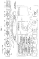
- FIG. 1 is a diagram that schematically illustrates the configuration of a storage system as an example of an embodiment
- FIG. 2 is a diagram that illustrates the hardware configuration thereof.
- the storage system 1, as illustrated in FIG. 1 is equipped with: one or more (six in the example illustrated in FIG. 1 ) hosts (superordinate apparatuses) 50-1 to 50-6; a plurality of (two in the example illustrated in FIG. 1 ) switches 40-1 and 40-2; and a virtual storage system 100.
- the storage system 1 is a scale-out type system, and the scale of the system can be extended by arbitrary connecting (additionally installing) a storage unit 30 or the processor unit 10.
- a new processor unit 10-3 is additionally installed to the virtual storage system 100 that includes two processor units 10-1 and 10-2.
- reference numeral 10 when one of a plurality of processor units needs to be specified, one of reference numerals 10-1 to 10-3 will be used, but, when an arbitrary processor unit is represented, reference numeral 10 will be used. In addition, the processor unit 10 will be described later in detail.
- the hosts 50-1 to 50-6 are respectively computers each having a server function. Such hosts 50-1 to 50-6 perform data writing or data reading by accessing to a virtual disk (virtual volume) 2 provided by the virtual storage system 100.
- the hosts 50-1 to 50-6 have the same configuration.
- a reference numeral that represents a host when one of a plurality of hosts needs to be specified, reference numerals 50-1 to 50-6 will be respectively used, but, when an arbitrary host is represented, reference numeral 50 will be used.
- the host 50-1 may be represented as host #1.
- the hosts 50-2 to 50-6 may be represented as hosts #2 to #6.
- Each host 50 as illustrated in FIG. 2 , is equipped with a plurality of (two in the example illustrated in FIG. 2 ) host adapters 51, and the host adapters 51 are connected to ports 41 included in the switches 40-1 and 40-2 through communication lines such as LAN cables.
- the hosts 50-1 to 50-6 are communicably connected to the processor units 10 of the virtual storage system 100 through the switch 40-1.
- the hosts 50-1 to 50-6 are communicably connected to the processor units 10 also through the switch 40-2. Accordingly, the communication path connecting the hosts 50-1 to 50-6 and the processor units 10 is made redundant as a path formed through the switch 40-1 and a path formed through the switch 40-2.
- Each one of the hosts 50-1 to 50-6 and each one of the processor units 10, for example, are interconnected through an internet small computer system interface (iSCSI).
- iSCSI internet small computer system interface
- the switch 40 is a local area network (LAN) switch.
- a multi-path driver 52 is stored in a storage device such as a memory not illustrated in the figure, and, by executing the multi-path driver 52 using a processor not illustrated in the figure as well, access path switching control to be described later is realized.
- the multi-path driver 52 communicates with each processor unit 10 to be described later and is a program that controls an access to each virtual disk (virtual volume) 2 provided by each processor unit 10.
- the multi-path driver 52 manages an access path (logical path) to each virtual disk 2.
- Attribute information of either "Active” or "Standby” is set to the access path to the virtual disk 2.
- Standby an access to the virtual disk 2 connected through the access path cannot be made.
- an access to the virtual disk 2 connected through the access path can be made.
- the multi-path driver 52 has a function for setting "Active” or "Standby" to each access path to the virtual disk 2.
- the multi-path driver 52 sets (allocates) an access path to the virtual disk 2 in accordance with the access path generation instruction and sets the access path that has been set to be in the standby state.
- the multi-path driver 52 has a function for adding a new access path as a standby path.
- the multi-path driver 52 sets an access path (standby path) that is in the standby state to be in the active state, thereby changing the access path to an active path.
- the multi-path driver 52 is provided in the form being recorded in a computer readable recording medium such as a flexible disk, a CD (a CD-ROM, a CD-R, a CD-RW, or the like), a DVD (a DVD-ROM, a DVD-RAM, a DVD-R, a DVD+R, a DVD-RW, a DVD+RW, an HD DVD, or the like), a Blu-ray disc, a magnetic disk, an optical disc, or a magneto-optical disk.
- the computer reads the program from the recording medium, transmits the program to an internal storage device or an external storage device so as to be stored therein, and uses the stored program.
- the program may be configured to be recorded in a storage device (recording medium) such as a magnetic disk, an optical disk, or a magneto-optical disk and be provided for a computer from the storage device through a communication path.
- a program stored in the internal storage device (in this embodiment, a memory not illustrated in the figure), is executed by a microprocessor (not illustrated in the figure) of a computer.
- a program recorded on a recording medium may be configured to be read by a computer.
- the computer has a concept that includes hardware and an operating system and represents the hardware operating under the control of the operating system.
- the hardware In a case where the operating system is not necessary, and the hardware is operated by an application program only, the hardware in itself corresponds to the computer.
- the hardware is equipped at least with a microprocessor such as a CPU and a unit used for reading a computer program recorded on a recording medium, and the host 50 has the function as a computer.
- the switches 40-1 and 40-2 are communication devices (relay devices) that switch transmission destinations of data in the computer network.
- switches 40-1 and 40-2 have the same configuration.
- a reference numeral that represents a switch when one of a plurality of switches needs to be specified, reference numeral 40-1 or 40-2 will be used, but, when an arbitrary switch is represented, reference numeral 40 will be used.
- the switch 40-1 may be represented as switch #1
- the switch 40-2 may be represented as switch #2.
- Each switch 40 is equipped with a plurality of ports 41. Such a port 41 is connected to a host adapter 51 included in the host 50 and a host interface (I/F) 110 of the processor unit 10 through communication lines.
- I/F host interface
- 16-port switches 40-1 and 40-2 each being equipped with 16 ports 41 are provided.
- each switch 40 is equipped with a processor not illustrated in the figure that is used for controlling data transmission and the like.
- the virtual storage system 100 virtualizes the storage areas of storage devices 32 (actual disks) of the storage units 30-1 to 30-3 and provides users with virtual disks 2-1 to 2-7 that are not dependent on the types, the arranged locations, and the like of the storage devices 32 for the hosts 50 and the like.
- the virtual storage system 100 is equipped with: one or more (two in the example illustrated in FIG. 2 ) processor units 10-1 and 10-2; one or more (two in the example illustrated in FIG. 2 ) internal switches 20-1 and 20-2; and one or more (three in the example illustrated in FIG. 2 ) storage units 30-1 to 30-3.
- FIG. 1 for the convenience of description, parts of the virtual storage system 100 such as the internal switches 20-1 to 20-2 are not illustrated.
- the configuration is changeable in units of processor units, and a processor unit 10 can be arbitrary added or omitted.
- Each one of the storage units 30-1 to 30-3, as illustrated in FIG. 2 is equipped with one or more storage devices 32 and a plurality of (two in the example illustrated in FIG. 2 ) controller modules (CM) 31-1 and 31-2 and stores data.
- CM controller modules
- the storage units 30-1 to 30-3 have the same configuration.
- a reference numeral that represents a storage unit when one of a plurality of storage units needs to be specified, one of reference numerals 30-1 to 30-3 will be used, but, when an arbitrary storage unit is represented, reference numeral 30 will be used.
- the configuration is changeable in units of storage units 30, and a storage unit 30 can be arbitrary added or omitted.
- the storage device 32 is a storage device such as a hard disk drive (HDD) or a solid state drive (SSD) and stores various kinds of data.
- HDD hard disk drive
- SSD solid state drive
- the number of storage devices is not limited thereto.
- four or less storage devices 32 or six or more storage devices 32 may be provided.
- each storage unit 30 a logical unit is configured by one or a plurality of the storage devices 32.
- redundant arrays of inexpensive disks RAID may be configured by a plurality of the storage devices 32.
- the configuration of the storage unit 30 is changeable in units of storage devices 32, and a storage device 32 can be arbitrarily added or omitted.
- the CMs 31-1 and 31-2 perform various control operations such as controlling an access to data stored inside the storage unit 30 and controls an access to the storage device 32 in accordance with a storage access request (access control signal) supplied from the processor unit 10.
- the CMs 31-1 and 31-2 have the same functional configuration.
- the CMs 31-1 and 31-2 are connected to the processor units 10-1 and 10-2 through the internal switches 20-1 and 20-2 and control the storage device 32 in accordance with a command such as "read” or "write” supplied from the host 50.
- the internal switches 20-1 and 20-2 switch the transmission destinations of data inside the virtual storage system 100.
- Such internal switches 20-1 and 20-2 have the same configuration.
- a reference numeral that represents an internal switch when one of a plurality of internal switches needs to be specified, one of reference numerals 20-1 and 20-2 will be used, but, when an arbitrary internal switch is represented, reference numeral 20 will be used.
- processor unit 10-1 may be referred to as processor unit #1.
- processor unit 10-2 may be referred to as processor unit #2
- processor unit 10-3 may be referred to as processor unit #3.
- a processor unit 10-3 that is newly added to this storage system 1 will be referred to as new processor unit or an additionally installed processor unit and may be represented by reference numeral 10-3 or #3.
- each processor unit 10 is configured to be able to realize the function as the master processor unit.
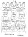
- FIG. 3 is a diagram that illustrates an exemplary hardware configuration of the processor unit 10 of the storage system 1 as an example of the embodiment.
- the host I/F (communication unit) 110 is a communication control device used for performing data communication with the above-described host 50
- the storage I/F 111 is a communication control device used for performing data communication with the storage unit 30.
- the LAN I/F 112 is a communication device used for performing data communication with the other processor units 10.
- the host I/F 110, and the storage I/F 111 various interface devices that are well known may be used.
- the memory 115 is a storage device that includes a ROM and a RAM.
- an operating system (OS) 1154 In the ROM of the memory 115, an operating system (OS) 1154, a software program (firmware: control program) relating to virtual disk control, and data used for this program are written.
- the OS 1154 on the memory 115 and various software programs are appropriately read and executed by the CPU 114.
- a firmware 1150 stored in the memory 115 has modules that realize the functions as a data access control unit 1151, a data storage control unit 1152, and a unit managing unit 1153.
- the data access control unit 1151 controls an access from the host 50 and, for example, controls a data access from the host 50 to the virtual disk 2.
- the data storage control unit 1152 controls an access to each storage unit 30.
- the unit managing unit 1153 performs various control operations used for building the virtual disk system. For example, the unit managing unit 1153 sets the virtual disks 2 and performs mapping between the virtual disks 2 and the storage devices 32 included in the storage unit 30 and the like.
- the data access control unit 1151, the data storage control unit 1152, and the unit managing unit 1153 realize the functions as a detection unit 11, a transmission unit 12, a load information collecting unit 13, a performance information collecting unit 14, a selection unit 15, a movement instruction unit 16, and a virtual disk managing unit 17, which will be described later, in cooperation with one another.
- the RAM of the memory 115 is used as a primary storage memory or a working memory.
- performance score information 101 In the memory 115 of the master processor unit 10-1, performance score information 101, load recording information 102, target load information 103, and an in-charge list 104, which will be described later, are stored.
- the CPU 114 serves as the virtual disk managing unit 17, the detection unit 11, the transmission unit 12, the load information collecting unit 13, the performance information collecting unit 14, the selection unit 15, and the movement instruction unit 16.
- the program stored in the internal storage device (the memory 115 in this embodiment) is executed by the microprocessor (the CPU 114 in this embodiment) of the computer.
- the program recorded on a recording medium may configured to be read through a reading device not illustrated in the figure and be executed by the computer.
- the processor unit 10 has a function as the computer.
- the virtual disk managing unit 17 forms the storage devices 32 mounted in the storage units 30 as a pool and performs clustering of the processor units 10, thereby realizing a virtual disk 2.
- the setting of the virtual disk 2 in the processor unit 10 may be realized by using a known technique, and thus, the description thereof will not be presented.
- virtual disks 2-1 to 2-4 are included in the processor unit 10-1.
- virtual disks 2-5 to 2-7 are included in the processor unit 10-2.
- each one of the processor units 10-1 and 10-2 corresponds to third control unit that manages the plurality of virtual volumes 2.
- the detection unit 11 detects (recognizes) that the new processor unit 10 has been additionally installed (connected) to this storage system 1.
- the detection unit 11 may detect the new processor unit 10-3 through the LAN I/F 112, the host 50, or the like.
- the load information collecting unit 13 causes each one of the processor units 10-1 and 10-2 including the virtual disk 2 to measure the iops/data transmission amount for each access path to the virtual disk 2 managed (taken charge) thereby.
- the load information collecting unit 13 registers the iops/data transmission amount transmitted from each processor unit 10 in the load recording information 102.
- the load recording information 102 is configured by mapping the iops/ data transmission amount on information that specifies the virtual disk 2.
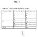
- FIG. 4 is a diagram that illustrates exemplary load recording information 102 in the storage system 1 as an example of the embodiment.
- the storage system 1 illustrated in FIG. 1 is equipped with four virtual disks 2-1 to 2-4 denoted by ID1 to ID4 in the processor unit #1 and is equipped with three virtual disks 2-5 to 2-7 specified by the ID1 to ID3 in the existing processor unit #2.
- the iops/data transmission amount is stored as a load recording for each one of the existing virtual disks 2 (in-charge volume) of the storage system 1.
- a sum of the iops/data transmission amount of the virtual disks 2 is 50.
- This load recording information 102 for example, is stored in the memory 115 or the storage device 116 of the master processor unit 10-1.
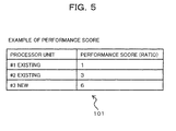
- the performance information collecting unit 14 collects the performance information of each processor unit 10 arranged inside the storage system 1. More specifically, the performance information collecting unit 14 causes all the processor units 10 including the new processor unit 10-3 to execute a performance checking program stored in advance in the storage device 116 or the like of each processor unit 10.
- the performance information collecting unit 14 manages the performance score transmitted from each processor unit 10 as the performance score information 101.
- FIG. 5 is a diagram that illustrates exemplary performance score information 101 in the storage system 1 as an example of the embodiment.
- the performance information collecting unit 14 acquires the performance information of each processor unit 10 included in the storage system 1, for example, when this storage system 1 is built. In addition, when the additional installation of a new processor unit 10 to this storage system 1 is recognized by the detection unit 11, the performance information collecting unit 14 acquires the performance information also from the newly connected processor unit 10.
- the method of acquiring the performance information using the performance information collecting unit 14 is not limited to the method in which a performance score is acquired by causing each processor unit 10 to execute the performance checking program, but may be variously changed.
- the performance information may be acquired by reading information (for example, a performance value or a bench mark result of the mounted CPU 114 or the like) representing the processing performance of each processor unit 10 presented by the manufacturer thereof or the like through a network or a recording medium.
- the selection unit 15 selects a virtual volume (moving virtual volume) 2 to be moved to the newly added processor unit 10 from among the virtual volumes managed by each processor unit 10 based on the performance scores (performance information) collected by the performance information collecting unit 14.
- the selection unit (target load setting unit) 15 determines a target load of each processor unit 10 in accordance with the performance information of each processor unit 10 including the new processor unit 10.
- the selection unit 15 determines the target load of each processor unit 10 by distributing a sum value (50 in the example illustrated in FIG. 4 ) of the load recordings of the existing virtual volume 2 that is included in the load recording information 102 in accordance with the performance information of all the processor units 10 including the new processor unit #3.
- a load in-charge load
- the selection unit 15 registers the determined target load of each processor unit 10 in the target load information 103.
- FIG. 6 is a diagram that illustrates exemplary target load information 103 in the storage system 1 as an example of the embodiment.
- the target load information 103 illustrated in FIG. 6 is configured by associating a target load set by the selection unit 15 with each processor unit 10.
- a sum value of the load recordings (iops/data transmission amount) of the processor units #1 and #2 is 50.
- the performance score ratio of the processor units #1, #2, and #3 is 1 : 3 : 6.
- the target load information 103 the values of the target loads acquired as described above are respectively registered.
- the selection unit 15 selects the virtual disk 2 to be moved to the new processor unit #3 by referring to the load recording information 102 and the target load information 103 described above.
- the selection unit 15 allocates the virtual disks 2 by using the in-charge list 104 as illustrated in FIG. 7 .
- the in-charge list 104 represents that which one of the plurality of processor units 10 including the new processor unit 10 is in charge of each virtual disk 2 included in this storage system 1.
- FIG. 7 is a diagram that illustrates an exemplary in-charge list 104 in the storage system 1 as an example of the embodiment.
- the in-charge list 104 is configured by further associating a newly allocated processor unit as an item with the load recording information 102 illustrated in FIG. 4 .
- each virtual disk 2 is configured to be associated with the load recording (iops/ data transmission amount) and the newly allocated processor unit.
- the newly allocated processor unit represents a processor unit 10 that is in charge of each virtual disk 2 (in-charge volume) in the storage system 1 of which the configuration has been changed by additionally installing the new processor unit #3.
- this in-charge list 104 In the initial state of this in-charge list 104, to each virtual disk 2, information (a flag or the like) indicating that a processor unit (in-charge processor unit) 10 that is in charge of the virtual disk 2 has not been determined is set (not illustrated in the figure). In addition, in the in-charge list 104 that is in the initial state, as a newly allocated processor unit corresponding to each virtual disk, the original processor unit 10 that manages the virtual disk 2 is registered.
- the selection unit 15 selects one having a largest value of the load recoding out of virtual disks 2 for which an in-charge processor unit 10 has not been determined in the in-charge list 104 and determines whether or not the selected virtual disk 2 is allocatable to the new processor unit 10.
- the selection unit 15 determines that the selected virtual disk 2 is allocatable.
- the selection unit 15 determines that the selected virtual disk 2 is not allocatable.
- the selection unit 15 selects the virtual disk 2 in a range in which a sum of the load recordings does not exceed the target load of the new processor unit 10 and determines the selected virtual disk 2 as the moving virtual disk 2. In addition, at this time, the selection unit 15 sequentially selects virtual disks 2 starting from a virtual disk 2 having a largest value of the load recording by referring to the load recording information 102 and determines whether or not a sum value of the load recordings of the selected virtual disks 2 is less than the target load of the new processor unit 10.
- the number of virtual disks 2 to be moved to the new processor unit 10 can be decreased, and a time or a load required for the process performed by the movement instruction unit 16 to be described later can be reduced.
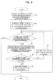
- FIG. 8 the method of determining the moving virtual disks 2 in the storage system 1 as an example of the embodiment will be described with reference to FIG. 8 .
- a new processor unit #3 is additionally installed to the storage system 1 including processor units #1 and #2.
- Step A1 the performance information collecting unit 14 causes each processor unit 10 to execute the performance checking program, thereby acquiring the performance score of each processor unit 10.
- the performance information collecting unit 14 generates performance score information 101 based on the collected performance scores.
- Step A2 the performance information collecting unit 14 generates target load information 103 based on the generated performance score information 101 and the load recording information 102 generated by the load information collecting unit 13.
- Step A3 the selection unit 15 checks whether or not there is a virtual disk (volume) 2 of which the in-charge processor unit 10 has not been determined by referring to the in-charge list 104.
- Step A4 a virtual disk 2 having a largest load recording out of the virtual disks 2 of which the in-charge processor unit 10 has not been determined is selected as a moving candidate. Then, the selection unit 15 calculates a sum of the load recordings of the new processor unit 10 in a case where the virtual disk 2 selected as the moving candidate is moved to the new processor unit 10.
- Step A5 the sum of the load recordings of the new processor unit 10 and the target load of the new processor unit 10 are compared with each other.
- the sum of the load recordings of the new processor unit 10 does not exceed the target load of the new processor unit 10 (see the route of NO in Step A5)
- Step A7 the new processor unit 10 is determined to be in charge of the virtual disk 2 that is the moving candidate. Thereafter, the process is returned to Step A3.
- Step A6 the processor unit 10 that is in charge of the virtual disk 2 that is the moving candidate is not changed. In other words, the original processor unit 10 is maintained to be in charge of the virtual disk 2 that is the moving candidate. Thereafter, the process is returned to Step A3.
- In-charge volume 1 (load recording of 15) of the processor unit #2 in-charge volume 1 (load recording of 12) of the processor unit #1
- in-charge volume 2 (load recording of 9) of the processor unit #2 in-charge volume 2 (load recording of 8) of the processor unit #1
- in-charge volume 3 (load recording of 3) of the processor unit #2 in-charge volume 3 (load recording of 2) of the processor unit #1
- in-charge volume 4 (load recording of 1) of the processor unit #1 In-charge volume 1 (load recording of 15) of the processor unit #2, in-charge volume 1 (load recording of 12) of the processor unit #1, in-charge volume 2 (load recording of 9) of the processor unit #2, in-charge volume 2 (load recording of 8) of the processor unit #1, in-charge volume 3 (load recording of 3) of the processor unit #2, in-charge volume 3 (load recording of 2) of the processor unit #1, and in-charge volume 4 (load recording of 1) of the processor unit #1.
- the target load of the new processor unit #3 is 30.
- a sum of the load recordings of the new processor unit 10 is the target load or more. Accordingly, such virtual disks 2 are not moved to the new processor unit 10.
- the new processor unit 10 is determined to be in charge of the in-charge volume 3 (load recording of 2) of the processor unit #1 selected as the moving candidate next.
- the in-charge volumes of the new processor unit #3 the in-charge volume 1 (load recording of 15) of the processor unit #2, the in-charge volume 1 (load recording of 12) of the processor unit #1, and the in-charge volume 3 (the load recording of 2) of the processor unit #1 are determined.
- the movement instruction unit 16 notifies the new processor unit 10, which is a movement destination, of the moving virtual disk 2 selected by the selection unit 15 so as to cause the new processor unit 10 to move the virtual disk 2.
- the new processor unit 10 acquires information relating to a virtual disk 2 to be moved based on shared information (not illustrated in the figure) stored in the storage unit 30 and sets the virtual disk 2 by using the acquired information.
- the method of moving the virtual disk 2 between the processor units 10 in the storage system 1 may be realized using various techniques that are well known, and the detailed description thereof will not be presented.
- the new processor unit 10 When the moving of the virtual disk 2 is completed, the new processor unit 10 notifies the master processor unit 10-1 (transmission unit 12) thereof. In this notification, information (virtual disk ID) used for identifying the virtual disk 2 is included.
- the transmission unit 12 transmits a control signal used for an instruction for setting an access path to the new processor unit 10 to each host 50.
- the transmission unit 12 transmits a path switching instruction as a control signal for an instruction for setting an access path to the host 50.
- a path switching instruction for example, a specific command representing the path switching instruction, information (for example, the target ID of the iSCSI) used for accessing the new processor unit 10, and information (virtual disk ID) used for identifying the virtual disk 2 of the new processor unit 10 are included.
- an instruction for adding an access path to the virtual disk 2 moved to the new processor unit 10 as a standby path is included.
- the transmission unit 12 sets the access path to the virtual disk 2 in the processor unit 10, which is the movement source, as a standby path for the host 50. Thereafter, the transmission unit 12 sets the access path to the virtual disk 2 moved to the new processor unit 10 as an active path for the host 50. According to such a process, the switching of the access path from the host 50 to the virtual disk 2 is performed.
- the multi-path driver 52 of the host 50 that has received the path switching instruction performs a path search for the new processor unit 10 based on the information included in the path switching instruction and allocates the access path acquired as a result of the path search to the processor unit 10. In addition, at this time, the multi-path driver 52 generates the access path as a standby path.
- FIG. 9 is a sequence diagram that illustrates a method of switching an access path to a virtual disk 2 in the storage system 1 as an example of the embodiment.
- FIG. 9 illustrates an example in which the virtual disks 2 of the processor units #1 and #2 are moved to the new processor unit #3.
- a path switching instruction is transmitted from the master processor unit #1 to the host 50 (see arrow S3).
- this path switching instruction as described above, the information for accessing the new processor unit #3, information for identifying each virtual disk 2 to be moved to the new processor unit #3, and the access path generating instruction for the virtual disk 2 are included.
- the multi-path driver 52 of the host 50 performs a path search for the new processor unit #3 (see arrow S4), and the new processor unit #3 replies to the host 50 with information (path information) of the access path used for accessing each virtual disk 2 (See arrow S5).
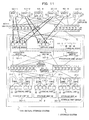
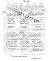
- FIGS. 11 and 12 are diagrams that illustrate an exemplary state when the new processor unit #3 is additionally installed in the storage system 1 as an example of the embodiment.
- FIG. 11 is a diagram that illustrates a state before the new processor unit #3 is additionally installed
- FIG. 12 is a diagram that illustrates a state after the new processor unit #3 is additionally installed.
- Step B5 the movement instruction unit 16 notifies the new processor unit #3 of the moving virtual disks 2 selected by the selection unit 15 and sets (moves) the virtual disks 2 to the new processor unit #3.
- Step B6 the transmission unit 12 transmits a path switching instruction for an instruction for setting an access path to the new processor unit #3 to the multi-path driver 52 of each host 50, as illustrated in FIG. 12 , switches the access path to the virtual disk 2 of the new processor unit #3, and ends the process.
- the selection unit 15 selects moving virtual disks 2, by sequentially selecting virtual disks 2 starting from the virtual disk 2 having a largest value of the load recording, the number of virtual disks 2 moved to the new processor unit 10 is decreased.
- the present invention is not limited thereto.
- the selection unit 15 selects virtual disks 2 to be moved to the new processor unit #3 such that the load of each processor unit 10 is smoothed in accordance with the processing performance of each processor unit 10.
- FIG. 13 is a diagram that illustrates exemplary load recording information 102 in the storage system 1 as a modified example of the embodiment.
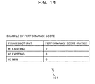
- FIG. 14 is a diagram that illustrates exemplary performance score information 101 thereof
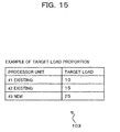
- FIG. 15 is a diagram that illustrates exemplary target load information 103 thereof
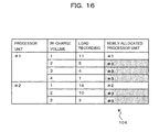
- FIG. 16 is a diagram that illustrates an exemplary in-charge list 104 thereof.
- the configurations thereof are the same as the configurations of those illustrated in FIGS. 4 to 7 .
- the selection unit 15 selects virtual disks 2 to be moved to the new processor unit #3 by referring to the load recording information 102 and the target load information 103 described above.
- this in-charge list 104 to each virtual disk 2, information (a flag or the like) indicating that a processor unit (in-charge processor unit) 10 that is in charge of the virtual disk 2 has not been determined is set (not illustrated in the figure).
- the in-charge list 104 that is in the initial state, as a newly allocated processor unit corresponding to each virtual disk, the original processor unit 10 that manages the virtual disk 2 is registered.
- the selection unit 15 determines that the selected virtual disks 2 is allocatable to the new processor unit #3. On the other hand, in a case where the sum of the load recordings of the remaining virtual disks 2 after excluding the selected virtual disks 2 is less than the target load of the processor unit 10, the selection unit 15 does not change the in-charge processor units so as to allow the original processor units #1 and #2 to be in charge of the selected virtual disks 2.
- the selection unit 15 for the existing processor units #1 and #2, calculates the sum of the load recordings of the remaining virtual disks 2 after excluding the virtual disks 2 selected as the moving virtual disks 2. Then, the selection unit 15 selects the moving virtual disks 2 in the range in which the sum of the load recordings of the remaining virtual disks 2 after excluding the virtual disks 2 selected as the moving virtual disks 2 is not less than each one of the target loads of the processor units #1 and #2 that are movement sources.
- the selection unit 15 sequentially selects virtual disks 2 starting from the virtual disk 2 having a smallest value of the load recording by referring to the load recording information 102 and determines whether or not a sum value of the remaining virtual disks 2 after excluding the selected virtual disks 2 is not less than the target load of the existing processor unit 10.
- the sum of the load recordings of the virtual disks 2 of the existing processor units 10 may be brought near the target load of the processor units 10, which can contribute to the smoothing of the loads.
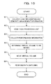
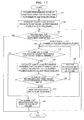
- Step C2 the performance information collecting unit 14 generates the target load information 103 based on the generated performance score information 101 and the load recording information 102 generated by the load information collecting unit 13.
- Step C3 the selection unit 15 checks whether or not the process of selecting moving virtual disks 2 has been performed for all the existing processor units 10.
- the process of selecting moving virtual disks 2 has been performed for all the existing processor units 10 (see the route of YES in Step C3), the process ends.
- Steps C4 to C9 is repeatedly performed for the number of times corresponding to the number (N) of all the existing processor units 10.
- Step C4 the selection unit 15 checks whether or not there is a virtual disk (volume) 2 of which the in-charge processor unit 10 has not been determined by referring to the in-charge list 104.
- Step C5 a virtual disk 2 having a smallest load recording is selected as a moving candidate from among the virtual disks 2 of which the in-charge processor unit 10 has not been determined. Then, the selection unit 15 assumes that the virtual disks 2 of the selected moving candidate are moved to the new processor unit 10 and calculates a sum of the load recordings of the remaining virtual disks 2 of the existing processor units 10 that are the movement sources.
- Step C6 the sum of the load recordings of the remaining virtual disks 2 of the existing processor units 10 that are the movement sources is compared with the target load of the processor unit 10. In a case where the sum of the load recordings of the remaining virtual disks 2 of the existing processor units 10 that are the movement sources is not less than the target load of the processor unit 10 (see the route of NO in Step C6), in Step C8, it is determined that the new processor unit 10 is in charge of the virtual disks 2 of the moving candidate. Thereafter, the process is returned to Step C4.
- Step C7 the processor unit 10 that is in charge of the virtual disks 2 of the moving candidate is not changed. In other words, the original processor unit 10 is maintained to be in charge of the virtual disks 2 of the moving candidate. Thereafter, the process is returned to Step C4.
- Step C9 the virtual disks 2 of which the existing processor units 10 are in charge are determined. Thereafter, N is incremented, and the process moves to the next existing processor unit 10 and is returned to Step C3.
- the arrangement of the in-charge volume 4 (load recording of 1), the in-charge volume 3 (load recording of 4), the in-charge volume 2 (load recording of 5), and the in-charge volume 1 (load recording of 11) is formed.
- the arrangement of the in-charge volume 3 (load recording of 3), the in-charge volume 2 (load recording of 10), and the in-charge volume 1 (load recording of 16) is formed.
- the target loads of the existing processor units #1 and #2 are 10 and 15.
- a sum of the load recordings of the remaining in-charge volumes of a case where the new processor unit #3 is in charge of the in-charge volume 4 (load recording of 1) is calculated.
- the sum of the load recordings of the remaining in-charge volumes of a case where the new processor unit #3 is in charge of the in-charge volume 2 is 11 and is not less than the target load of the processor unit #1 which is 10. Accordingly, it is determined that the new processor unit #3 is in charge of the in-charge volume 2 as well.
- the sum of the load recordings of the remaining in-charge volumes of a case where the new processor unit #3 is in charge of the in-charge volume 1 (load recording of 11) is 0 and is less than the target load of the processor unit #1 which is 10. Accordingly, it is determined that the original processor unit #1 is maintained to be in charge of the in-charge volume 1.
- the sum of the load recordings of the remaining in-charge volumes of a case where the new processor unit #3 is in charge of the in-charge volume 2 (load recording of 10) is 16 and is not less than the target load of the processor unit #2 which is 15. Accordingly, it is determined that the new processor unit #3 is in charge of the in-charge volume 2 as well.
- the sum of the load recordings of the remaining in-charge volumes of a case where the new processor unit #3 is in charge of the in-charge volume 1 is 0 and is less than the target load of the processor unit #2 which is 15. Accordingly, it is determined that the original processor unit #2 is maintained to be in charge of the in-charge volume 1.
- the in-charge volumes 2 to 4 of the processor unit #1 and the in-charge volumes 2 and 3 of the processor unit #2 are determined.
- the selection unit 15 selects virtual volumes 2 to be moved to the new processor unit 10 from among virtual volumes managed by each processor unit 10 based on the load recording information 102 generated by the load information collecting unit 13 and the performance score information 101 generated by the performance information collecting unit 14. Accordingly, the virtual disks 2 to be moved to the new processor unit 10 can be easily selected in accordance with the processing performance of each processor unit 10.
- the switching of the access path to the virtual disk 2 moved to the new processor unit 10 that has been additionally installed in the host 50 can be realized without stopping the operation of the storage system 1.
- the selection unit 15 determines the virtual disk 2 of the moving candidate as the moving virtual disk 2 of which the new processor unit 10 is in charge.
- the sum of the load recordings of the virtual disks 2 of the processor unit 10 that is the movement source is maintained at the target load of the processor unit 10, whereby the loads of the plurality of processor units 10 can be smoothed.
- the selection unit 15 sequentially selects the virtual disks starting from a virtual disk 2 having a lowest value of the load recording. Accordingly, the moving virtual disks 2 can be efficiently selected.
- the present invention is not limited thereto, and various changes may be made therein.
- the present invention may be applied to the rearrangement of processes performed in the nodes.
- the load information collecting unit 13 collects the load information (for example, a delay time relating to a predicted processing time) relating to processes distributed in the nodes, and the performance information collecting unit 14 collects the performance score (performance information) that represents the processor performance or the input/output processing performance of each server computer.
- load information for example, a delay time relating to a predicted processing time
- performance information the performance score that represents the processor performance or the input/output processing performance of each server computer.
- the selection unit 15 selects processes of which the processing is moved to a new computer that is additionally installed from the existing computers based on the load information and the performance information.
- the transmission unit 12 notifies hosts connected to the multi-node system of information relating to the processes moved to the new computer.
- a processor unit 10 may be additionally installed in a storage system 1 including three or more processor units 10 or one processor unit 10, and, at this time, two or more processor units 10 may be additionally installed.
- the present invention is not limited thereto. In other words, the number of the virtual disks 2 included in each processor unit 10 may be appropriately changed.
- the present invention is not limited thereto. In other words, five or less or seven or more hosts 50 may be configured to be included. Similarly, the number of the storage units 30 and the number of the storage devices 32 included in each storage unit may be variously changed.
- the load information collecting unit 13 uses the iops/data transmission amount as the load information for each access path
- the present invention is not limited thereto.
- information other than the iops/data transmission amount may be used as the performance index of the storage device.
Landscapes
- Engineering & Computer Science (AREA)
- Theoretical Computer Science (AREA)
- Human Computer Interaction (AREA)
- Physics & Mathematics (AREA)
- General Engineering & Computer Science (AREA)
- General Physics & Mathematics (AREA)
- Computer Networks & Wireless Communication (AREA)
- Information Retrieval, Db Structures And Fs Structures Therefor (AREA)
- Debugging And Monitoring (AREA)
Applications Claiming Priority (1)
| Application Number | Priority Date | Filing Date | Title |
|---|---|---|---|
| JP2013090128A JP2014215666A (ja) | 2013-04-23 | 2013-04-23 | 制御システム,制御装置及び制御プログラム |
Publications (1)
| Publication Number | Publication Date |
|---|---|
| EP2796984A1 true EP2796984A1 (en) | 2014-10-29 |
Family
ID=50624426
Family Applications (1)
| Application Number | Title | Priority Date | Filing Date |
|---|---|---|---|
| EP14165383.2A Withdrawn EP2796984A1 (en) | 2013-04-23 | 2014-04-22 | Control system, control apparatus, and control program |
Country Status (3)
| Country | Link |
|---|---|
| US (1) | US20140317348A1 (zh) |
| EP (1) | EP2796984A1 (zh) |
| JP (1) | JP2014215666A (zh) |
Families Citing this family (7)
| Publication number | Priority date | Publication date | Assignee | Title |
|---|---|---|---|---|
| US10097410B2 (en) | 2014-06-26 | 2018-10-09 | Vmware, Inc. | Methods and apparatus to scale application deployments in cloud computing environments |
| US10275007B2 (en) * | 2014-09-26 | 2019-04-30 | Intel Corporation | Performance management for a multiple-CPU platform |
| JP6394313B2 (ja) * | 2014-11-19 | 2018-09-26 | 富士通株式会社 | ストレージ管理装置、ストレージ管理方法及びストレージ管理プログラム |
| WO2016103506A1 (ja) * | 2014-12-26 | 2016-06-30 | 株式会社日立製作所 | パス管理装置及びパス管理方法 |
| JP6558090B2 (ja) | 2015-06-15 | 2019-08-14 | 富士通株式会社 | ストレージ管理装置、ストレージ管理方法及びストレージ管理プログラム |
| JP7332488B2 (ja) * | 2020-01-16 | 2023-08-23 | 株式会社日立製作所 | ストレージシステム及びストレージシステムの制御方法 |
| JP2022099948A (ja) * | 2020-12-23 | 2022-07-05 | 株式会社日立製作所 | ストレージシステムおよびストレージシステムにおけるデータ量削減方法 |
Citations (4)
| Publication number | Priority date | Publication date | Assignee | Title |
|---|---|---|---|---|
| JP2005050303A (ja) | 2003-07-14 | 2005-02-24 | Fujitsu Ltd | 分散型ストレージシステム |
| EP1727033A1 (en) * | 2005-05-24 | 2006-11-29 | Hitachi, Ltd. | Storage system and operation method of storage system |
| JP2008269338A (ja) | 2007-04-20 | 2008-11-06 | Hitachi Ltd | ストレージ装置及び管理単位設定方法 |
| EP2120138A2 (en) * | 2008-05-15 | 2009-11-18 | Hitachi Ltd. | Method and apparatus for I/O priority control in storage systems |
Family Cites Families (2)
| Publication number | Priority date | Publication date | Assignee | Title |
|---|---|---|---|---|
| US7069468B1 (en) * | 2001-11-15 | 2006-06-27 | Xiotech Corporation | System and method for re-allocating storage area network resources |
| JP4930934B2 (ja) * | 2006-09-29 | 2012-05-16 | 株式会社日立製作所 | データマイグレーション方法及び情報処理システム |
-
2013
- 2013-04-23 JP JP2013090128A patent/JP2014215666A/ja active Pending
-
2014
- 2014-04-18 US US14/256,339 patent/US20140317348A1/en not_active Abandoned
- 2014-04-22 EP EP14165383.2A patent/EP2796984A1/en not_active Withdrawn
Patent Citations (4)
| Publication number | Priority date | Publication date | Assignee | Title |
|---|---|---|---|---|
| JP2005050303A (ja) | 2003-07-14 | 2005-02-24 | Fujitsu Ltd | 分散型ストレージシステム |
| EP1727033A1 (en) * | 2005-05-24 | 2006-11-29 | Hitachi, Ltd. | Storage system and operation method of storage system |
| JP2008269338A (ja) | 2007-04-20 | 2008-11-06 | Hitachi Ltd | ストレージ装置及び管理単位設定方法 |
| EP2120138A2 (en) * | 2008-05-15 | 2009-11-18 | Hitachi Ltd. | Method and apparatus for I/O priority control in storage systems |
Also Published As
| Publication number | Publication date |
|---|---|
| JP2014215666A (ja) | 2014-11-17 |
| US20140317348A1 (en) | 2014-10-23 |
Similar Documents
| Publication | Publication Date | Title |
|---|---|---|
| EP2796984A1 (en) | Control system, control apparatus, and control program | |
| US7395370B2 (en) | Computer system, data management method, and program for determining a migration method based on prediction of a migration influence | |
| US8863139B2 (en) | Management system and management method for managing a plurality of storage subsystems | |
| US8706963B2 (en) | Storage managing system, computer system, and storage managing method | |
| US8521983B2 (en) | Program, apparatus and method for managing data allocation of distributed storage system including storage nodes | |
| US8850152B2 (en) | Method of data migration and information storage system | |
| JP4749140B2 (ja) | データマイグレーション方法及びシステム | |
| US8352595B2 (en) | Operation management system, management apparatus, management method and management program | |
| JP6476932B2 (ja) | ストレージ装置,制御プログラム,ストレージシステム及びデータ転送方法 | |
| US8447850B2 (en) | Management computer and computer system management method | |
| JP2008217216A (ja) | 負荷分散方法及び計算機システム | |
| WO2013157072A1 (ja) | 計算機システム、リソース管理方法及び管理計算機 | |
| US9928185B2 (en) | Information processing apparatus and computer-readable recording medium having program recorded therein | |
| US8185712B2 (en) | System and method for intelligent storage migration | |
| JP5104855B2 (ja) | 負荷分散プログラム、負荷分散方法、及びストレージ管理装置 | |
| US20150095592A1 (en) | Storage control apparatus, storage control method, and computer-readable recording medium having stored storage control program | |
| US20180341423A1 (en) | Storage control device and information processing system | |
| CN104603737A (zh) | 实现存储设备的高速访问和数据保护的计算机、计算机系统和i/o请求处理方法 | |
| US20140173144A1 (en) | Information processing apparatus, storage apparatus, information processing system, and input/output method | |
| US10481829B2 (en) | Information processing apparatus, non-transitory computer-readable recording medium having stored therein a program for controlling storage, and method for controlling storage | |
| US20150248369A1 (en) | Information processing apparatus and log output method | |
| JP2021041914A (ja) | 航空機を着陸させるための滑走路出口の決定 | |
| US20160224273A1 (en) | Controller and storage system | |
| US8850088B2 (en) | Management system and management method | |
| US20100262803A1 (en) | Storage system and storage control method |
Legal Events
| Date | Code | Title | Description |
|---|---|---|---|
| PUAI | Public reference made under article 153(3) epc to a published international application that has entered the european phase |
Free format text: ORIGINAL CODE: 0009012 |
|
| 17P | Request for examination filed |
Effective date: 20140422 |
|
| AK | Designated contracting states |
Kind code of ref document: A1 Designated state(s): AL AT BE BG CH CY CZ DE DK EE ES FI FR GB GR HR HU IE IS IT LI LT LU LV MC MK MT NL NO PL PT RO RS SE SI SK SM TR |
|
| AX | Request for extension of the european patent |
Extension state: BA ME |
|
| R17P | Request for examination filed (corrected) |
Effective date: 20150325 |
|
| RBV | Designated contracting states (corrected) |
Designated state(s): AL AT BE BG CH CY CZ DE DK EE ES FI FR GB GR HR HU IE IS IT LI LT LU LV MC MK MT NL NO PL PT RO RS SE SI SK SM TR |
|
| 17Q | First examination report despatched |
Effective date: 20150930 |
|
| STAA | Information on the status of an ep patent application or granted ep patent |
Free format text: STATUS: THE APPLICATION IS DEEMED TO BE WITHDRAWN |
|
| 18D | Application deemed to be withdrawn |
Effective date: 20161125 |