EP2796728A1 - Hydraulikzylinder - Google Patents
Hydraulikzylinder Download PDFInfo
- Publication number
- EP2796728A1 EP2796728A1 EP20140401044 EP14401044A EP2796728A1 EP 2796728 A1 EP2796728 A1 EP 2796728A1 EP 20140401044 EP20140401044 EP 20140401044 EP 14401044 A EP14401044 A EP 14401044A EP 2796728 A1 EP2796728 A1 EP 2796728A1
- Authority
- EP
- European Patent Office
- Prior art keywords
- cylinder
- protective tube
- cylinder housing
- hydraulic
- end pieces
- Prior art date
- Legal status (The legal status is an assumption and is not a legal conclusion. Google has not performed a legal analysis and makes no representation as to the accuracy of the status listed.)
- Granted
Links
Images



Classifications
-
- F—MECHANICAL ENGINEERING; LIGHTING; HEATING; WEAPONS; BLASTING
- F15—FLUID-PRESSURE ACTUATORS; HYDRAULICS OR PNEUMATICS IN GENERAL
- F15B—SYSTEMS ACTING BY MEANS OF FLUIDS IN GENERAL; FLUID-PRESSURE ACTUATORS, e.g. SERVOMOTORS; DETAILS OF FLUID-PRESSURE SYSTEMS, NOT OTHERWISE PROVIDED FOR
- F15B15/00—Fluid-actuated devices for displacing a member from one position to another; Gearing associated therewith
- F15B15/20—Other details, e.g. assembly with regulating devices
-
- F—MECHANICAL ENGINEERING; LIGHTING; HEATING; WEAPONS; BLASTING
- F15—FLUID-PRESSURE ACTUATORS; HYDRAULICS OR PNEUMATICS IN GENERAL
- F15B—SYSTEMS ACTING BY MEANS OF FLUIDS IN GENERAL; FLUID-PRESSURE ACTUATORS, e.g. SERVOMOTORS; DETAILS OF FLUID-PRESSURE SYSTEMS, NOT OTHERWISE PROVIDED FOR
- F15B15/00—Fluid-actuated devices for displacing a member from one position to another; Gearing associated therewith
- F15B15/02—Mechanical layout characterised by the means for converting the movement of the fluid-actuated element into movement of the finally-operated member
- F15B15/04—Mechanical layout characterised by the means for converting the movement of the fluid-actuated element into movement of the finally-operated member with oscillating cylinder
Definitions
- the invention relates to a hydraulic cylinder according to the preamble of claim 1.
- Such hydraulic cylinders have become known in practice. These hydraulic cylinders are fastened by a fastening device on the cylinder housing foot and on the opposite piston rod end between the components to be adjusted to each other.
- a fastening device on the cylinder housing foot and on the opposite piston rod end between the components to be adjusted to each other.
- the arrangement of the fastening device on the cylinder base is not possible in any structural design.
- Some hydraulic cylinders are made of corrosive material. When using a conventional hydraulic cylinder there is often the risk of material weakening of the components by corrosion, especially if they are used in a chemically aggressive area, as is the case for example when installed in fertilizer spreaders.
- a protective tube is placed on the hydraulic cylinder housing.
- the protective tube is made of a non-corrosive material and is firmly connected to the hydraulic cylinder housing and protects the cylinder housing from corrosion.
- the respective cylinder heads are mounted by means of a screw on the cylinder tube, this method of attachment of the cylinder heads represents an increased assembly cost.
- the invention has for its object to easily achieve a compact design of the hydraulic cylinder and its protection against corrosion.
- the protective tube-like element absorbs forces and transmits them between the components to be adjusted. This is ensured by the positive connection between the protective tube-like element and the end pieces.
- a clear and secure positioning and concomitant fixation of the protective tube-like element in a hydraulic cylinder with two hydraulic line connections can be achieved in that the hydraulic line connection elements are arranged on the end pieces, that the protective tube-like element is arranged by at least one hydraulic line connection element in a secured manner to the cylinder housing.
- the fastening device associated with the cylinder housing is arranged on the protective tube-like element, so that the protective tube-like element extends beyond the cylinder housing on its one side in that the fastening device is arranged in the end region of the extended region of the protective tube-like element.
- the hydraulic cylinder as Synchronization cylinder is formed with protruding from both bottoms of the cylinder housing piston rods and that the protective tube-like element protrudes beyond the end of a piston rod.
- the protective tube-like element consists of two joinable half-pipe shell elements. This makes it possible that the existing of two shells protection tube-like element just to put the cylinder housing with the deferred end pieces and to fix accordingly.
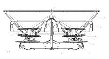
- the distribution machine designed as a two-disc fertilizer spreader has the storage container 3 divided by a roof-shaped central part 1 in its lower area into two discharge funnels 2.
- the reservoir 3 is provided with a frame, not shown, via which the centrifugal fertilizer spreader is to be arranged on the three-point hitch of an agricultural tractor.
- a metering device 4 is arranged in each case.
- a gear block 5 which is arranged on the frame, not shown, outstanding and rotatably driven shafts 6 centrifugal discs 7 arranged thereon with throwing elements 8.
- the centrifugal discs 7 rotate in a known manner in opposite directions of rotation.
- the respective metering device 4 has a pot-shaped funnel element 9, in the bottom 10 of which at least one passage opening formed as an outlet opening 11 is arranged.
- the outlet opening 11 acts with a slider 12 together.
- the slider 12 is arranged pivotably with respect to the passage opening 11 on a pivot pin 14 mounted on the bottom 10 of the metering device 4 in the pivot sleeve 13.
- the slide 12 is to be pivoted by means of a trained as a hydraulic synchronizing cylinder 15 adjustment to the pivot pin 14 extending through the pivot axis in its respective closed or open position.
- the pivot lever 17 of the Mengeneinstell Rhein 16 is also pivotally mounted.
- the pivot lever 17 is thus mounted on the pivot pin 14 on which the slider 12 is pivotally mounted.
- the pivot lever 17 is to be fixed to the arranged on the reservoir 3 setting scale 18 by means of suitable fixing elements 19 in the respectively desired position.
- the hydraulic synchronizing cylinder 15 is on the one hand via the protective tube-like element 20, which will be explained in the further course, attached to the slider 12 and on the other hand to the pivot lever 17 by means of connecting elements 21.1 and 21.2.
- the adjusting element designed as a hydraulic synchronizing cylinder 15 is arranged directly between the slider 12 and the pivoting lever 17 of the quantity setting device 16.
- the two hydraulic connections 22.1 and 22.2 of the hydraulic synchronizing cylinder 15 are connected in a manner not shown via hydraulic lines to a hydraulic system, such as those of the spreader carrying tractor, in a known manner.
- the adjusting element formed as a hydraulic synchronizing cylinder 15 has the cylinder tube 23 designed as a cylinder housing.
- the sections 26.1 and 26.2 are connected to each other in a known manner via a screw connection.
- the cylinder tube 23 is sealed at its ends with preferably identical configured end pieces 27.
- the end pieces 27 have an internal annular groove 28 with the inserted O-ring 28.1. These annular grooves 28 with O-ring 28.1 serve to seal the respective end piece 27 on the cylinder tube 23.
- end pieces 27 seal with their respective inner surface to the respective outer surface of the cylinder tube 23 to the end pieces 27, the cylinder tube 23 each end , The end pieces 27 are pushed up to the stop on the end faces of the cylinder tube 23. Furthermore, the end pieces 27 have two further annular grooves 29 and 30.
- the annular groove 29 has the O-ring 29.1 and serves to seal the cylinder 15 to the outside.
- the annular groove 30 is designed as a scraper.
- At the end pieces 27 are still each one of the hydraulic connections 22.1 and 22.2 are arranged, which are attached to the end pieces 27 material or threadedly.
- cylinder tube 23 and the end pieces 27 is a, at least over the portion 26.1 protruding, protective tube-like element 20, which consists of two half-shells 31.1 and 31.2 arranged.
- the shell groove 32.1 and the shell web 32.2 are provided. After joining the two half-shells 31.1 and 31.2 are on the interlocking shell groove 32.1 and shell web 32.2 positively into one another and form the protective tube-like element 20.
- the protective tube-like element 20 further prevents a displacement of the half-shells 31.1 and 31.2 to each other.
- the shell groove 32.1 and the shell web 32.2 form in the superimposed state of half-shell 31.1 and 31.2 a kind of labyrinth seal.
- the gap created in the assembled state of the protective tube-like member 20 and the cylinder tube 23 can be used as a kind of protective bag receiving pocket.
- the resulting labyrinth seal prevents leakage of the protective compound.
- the protective compound may be, for example, viscous grease. Grease offers itself for cost reasons. Due to the grease, the cylinder tube 23, which consists of cost and manufacturing reasons of a corrosive material, well protected inexpensively.
- the two annular surfaces 33.1 and 33.2 arise on the protective tube-like element 20. These annular surfaces 33.1 and 33.2 are each provided for receiving a clamp 34 to hold the two half-shells 31.1 and 31.2 in a simple manner and / or a mutual release of the two half shells 31.1 and 31.2 to prevent.
- the protective tube-like element 20 forms a positive-locking collar around the two hydraulic connections 22.1 and 22.2. Furthermore, the protective tube-like element 20 closes positively with its inner end face with the end face of the end piece 27, which is turned towards the connecting element 21.2. By skillful positive arrangement of the protective tube-like element this can used to transmit forces, starting from the synchronizing cylinder 15.
- the protective tube-like element 20 has at the end of the protruding in the retracted position portion 26.1 a preferably circular material recess 35 to secure the protective tube-like element 20 on the pivot lever 17, wherein the circular material recess 35 is located behind the maximum extended position of the piston rod 25.
- six elongate openings 36 are preferably mounted per half shell 31.1 and 31.2, via which impurities which are located in the vicinity of the section 26.1 can be removed.
- the slider 12 has an extension which extends at least over twice the opening angle of the outlet opening 11, such as the Fig. 3 can be seen.
Landscapes
- Engineering & Computer Science (AREA)
- Physics & Mathematics (AREA)
- Fluid Mechanics (AREA)
- Mechanical Engineering (AREA)
- General Engineering & Computer Science (AREA)
- Actuator (AREA)
Abstract
Description
- Die Erfindung betrifft einen Hydraulikzylinder gemäß dem Oberbegriff des Anspruches 1.
- Derartige Hydraulikzylinder sind in der Praxis bekannt geworden. Diese Hydraulikzylinder sind durch eine Befestigungsvorrichtung am Zylindergehäusefuß und am gegenüberliegenden Kolbenstangenende zwischen den zueinander zu verstellenden Bauteilen befestigt. Bei Einsatz eines konventionellen Hydraulikzylinders ist die Anordnung der Befestigungsvorrichtung am Zylinderfuß nicht in jeder baulichen Ausführung möglich.
- Einige Hydraulikzylinder sind aus korrosivem Werkstoff gefertigt. Bei dem Einsatz eines herkömmlichen Hydraulikzylinders besteht häufig die Gefahr einer materiellen Schwächung der Bauteile durch Korrosion, insbesondere wenn sie in einem chemisch aggressiven Bereich eingesetzt werden, wie diese beispielsweise beim Einbau in Düngerstreuern der Fall ist.
- In der Praxis wird ein Schutzrohr auf das Hydraulikzylindergehäuse aufgesetzt. Das Schutzrohr besteht aus einem nicht korrodierenden Material und ist fest mit dem Hydraulikzylindergehäuse verbunden und schützt das Zylindergehäuse vor Korrosionen. Weiterhin sind die jeweiligen Zylinderköpfe mittels einer Schraubverbindung am Zylinderrohr angebracht, diese Anbringungsart der Zylinderköpfe stellt einen erhöhten Montageaufwand dar.
- Der Erfindung liegt die Aufgabe zugrunde, auf einfache Weise eine kompakte Ausgestaltung des Hydraulikzylinders und deren Schutz vor Korrosion zu erreichen.
- Diese Aufgabe wird erfindungsgemäß dadurch gelöst, dass die Endstücke jeweils mittels einer Schiebeführung auf die jeweiligen Enden des Zylindergehäuses in abdichtender Weise aufgeschoben sind, dass die beiden Endstücke mittels geeigneter Mittel mit dem schutzrohrähnlichen Element formschlüssig verbunden sind.
- Infolge dieser Maßnahmen, dass die Endstücke nur auf das Zylinderrohr aufgeschoben sind, ist ein verringerter Montageaufwand gegeben. Weiterhin nimmt das schutzrohrähnliche Element Kräfte auf und überträgt diese zwischen den zu verstellenden Bauteilen. Dies wird durch die formschlüssige Verbindung zwischen dem schutzrohrähnlichen Element und den Endstücken gewährleistet.
- Eine eindeutige und sichere Positionierung und eine damit einhergehende Fixierung des schutzrohrähnlichen Elementes bei einem Hydraulikzylinder mit zwei Hydraulikleitungsanschlüssen lässt sich dadurch erreichen, dass die Hydraulikleitungsanschlusselemente an den Endstücken angeordnet sind, dass das schutzrohrähnliche Element durch zumindest ein Hydraulikleitungsanschlusselement in gesicherter Weise an dem Zylindergehäuse angeordnet ist.
- Eine axiale Verschiebung der aufgesteckten Endstücke auf dem Zylinderrohr wird dadurch verhindert, dass an beiden Endstücken Hydraulikleitungsanschlusselemente angeordnet sind, dass das schutzrohrähnliche Element mit den beiden Hydraulikleitungsanschlusselementen in formschlüssiger Weise verbunden ist.
- Um eine Verschmutzung der Kolbenstange, auf der Seite an der kein zu verstellendes Bauteil angeschlossen ist, zu minimieren, ist vorgesehen, dass die dem Zylindergehäuse zugeordnete Befestigungsvorrichtung an dem schutzrohrähnlichen Element angeordnet ist, dass das schutzrohrähnliche Element auf seiner einen Seite über das Zylindergehäuse hinaus verlängert ist, dass in dem Endbereich des verlängerten Bereiches des schutzrohrähnlichen Elementes die Befestigungsvorrichtung angeordnet ist.
- Damit die Kräfte und Geschwindigkeiten beim ein- und ausfahren, bei dem eigentlichen Zylinder und den zu verstellenden Elementen, vom Betrag her gleich sind, ist vorgesehen, dass der Hydraulikzylinder als Gleichlaufzylinder mit aus beiden Böden des Zylindergehäuses herausragenden Kolbenstangen ausgebildet ist und dass das schutzrohrähnliche Element über das Ende der einen Kolbenstange hinausragt.
- Um den Montageaufwand zu verringern, besteht das schutzrohrähnliche Element aus zwei zusammenfügbaren Halbrohrschalenelementen. Hierdurch wird ermöglicht, dass das aus zwei Schalen bestehende schutzrohrähnliche Element einfach um das Zylindergehäuse mit den aufgeschobenen Endstücken zu legen und entsprechend zu fixieren.
- Weitere Einzelheiten der Erfindung sind der Beispielsbeschreibung und den Zeichnungen zu entnehmen. Hierbei zeigen
- Fig. 1
- den Schleuderstreuer in der Ansicht von hinten und in Prinzipdarstellung,
- Fig. 2
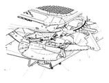
- den in Fahrtrichtung gesehen linken Bereich des Streuers in perspektivischer Darstellung und in vergrößertem Maßstab,
- Fig. 3
- der Boden mit Auslauföffnung und Schieber der Dosiereinrichtung mit Mengeneinstellung "0" und eingefahrenem Einstellelement in der Draufsicht,
- Fig. 4
- der Boden mit Auslauföffnung und Schieber der Dosiereinrichtung mit Mengeneinstellung "0" und ausgefahrenem Einstellelement in der Draufsicht,
- Fig. 5
- der Boden mit Auslauföffnung und Schieber der Dosiereinrichtung mit Mengeneinstellung "31" und eingefahrenem Einstellelement in der Draufsicht,
- Fig. 6
- der Boden mit Auslauföffnung und Schieber der Dosiereinrichtung mit Mengeneinstellung "31" und ausgefahrenem Einstellelement in der Draufsicht,
- Fig. 7
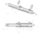
- der erfindungsmäßige Hydraulikzylinder mit dem Schutzrohrähnlichen Element in perspektivischer Ansicht,
- Fig. 8
- den Hydraulikzylinder gemäß
Fig. 7 in Schnittdarstellung für den Schnitt A. - Fig. 9
- den Hydraulikzylinder gemäß
Fig. 7 vor der Montage der Endstücke, auf das Zylinderrohr in perspektivischer Explosionsansicht. - Fig. 10
- den Hydraulikzylinder gemäß
Fig. 7 nach der Montage der Endstücke, auf das Zylinderrohr in perspektivischer Explosionsansicht. - Die als Zweischeibendüngerstreuer ausgebildete Verteilmaschine weist den durch ein dachförmiges Mittelteil 1 in seinem unteren Bereich in zwei Auslauftrichter 2 aufgeteilten Vorratsbehälter 3 auf. Der Vorratsbehälter 3 ist mit einem nicht dargestellten Rahmen versehen, über den der Schleuderdüngerstreuer an den Dreipunktkraftheber eines Ackerschleppers anzuordnen ist. An den unteren Enden der Auslauftrichter 2 ist jeweils eine Dosiereinrichtung 4 angeordnet. Unterhalb der Dosiereinrichtung 4 sind auf einem Getriebeblock 5, der an dem nicht dargestellten Rahmen angeordnet ist, herausragenden und rotierend antreibbaren Wellen 6 Schleuderscheiben 7 mit darauf angeordneten Wurfelementen 8 angeordnet. Die Schleuderscheiben 7 rotieren in bekannter Weise ineinander entgegengesetztem Drehsinn.
- Die jeweilige Dosiereinrichtung 4 weist ein topfförmiges Trichterelement 9 auf, in dessen Boden 10 zumindest eine als Auslassöffnung 11 ausgebildete Durchlassöffnung angeordnet ist. Die Auslassöffnung 11 wirkt mit einem Schieber 12 zusammen. Über den Schieber 12, der unterhalb des Bodens 10 des bodenförmigen Bereiches des Trichterelementes 9 der Dosiereinrichtung 4 angeordnet ist, ist die Auslassöffnung 11 verschließbar und in ihrer Öffnungsweise einstellbar. Der Schieber 12 ist an einem an dem Boden 10 der Dosiereinrichtung 4 in der Schwenkhülse 13 gelagerten Schwenkbolzen 14 verschwenkbar gegenüber der Durchlassöffnung 11 angeordnet.
- Der Schieber 12 ist mittels eines als hydraulischer Gleichlaufzylinder 15 ausgebildeten Verstellelementes um die durch den Schwenkbolzen 14 verlaufende Schwenkachse in seine jeweilige Schließ- oder Öffnungsstellung zu verschwenken. Auf dem Schwenkbolzen 14 ist weiterhin der Schwenkhebel 17 der Mengeneinstelleinrichtung 16 verschwenkbar gelagert. Der Schwenkhebel 17 ist somit auf dem Schwenkbolzen 14, auf dem der Schieber 12 verschwenkbar angeordnet ist, gelagert. Der Schwenkhebel 17 ist an der an dem Vorratsbehälter 3 angeordneten Einstellskala 18 mittels der geeigneten Festsetzelementen 19 in der jeweils gewünschten Position festzusetzen.
- Der hydraulische Gleichlaufzylinder 15 ist einerseits über das schutzrohrähnliche Element 20, welches im weiteren Verlauf noch erklärt wird, an dem Schieber 12 und andererseits an dem Schwenkhebel 17 mittels Verbindungselementen 21.1 und 21.2 befestigt. Somit ist das als hydraulischer Gleichlaufzylinder 15 ausgebildete Verstellelement unmittelbar zwischen dem Schieber 12 und dem Schwenkhebel 17 der Mengeneinstelleinrichtung 16 angeordnet. Die beiden Hydraulikanschlüsse 22.1 und 22.2 des hydraulischen Gleichlaufzylinders 15 sind in nicht dargestellter Weise über Hydraulikleitungen an eine Hydraulikanlage, beispielsweise die des den Schleuderstreuer tragenden Ackerschleppers, in bekannter Weise angeschlossen.
- Das als hydraulischer Gleichlaufzylinder 15 ausgebildete Verstellelement weist das als Zylindergehäuse ausgebildete Zylinderrohr 23 auf. In das Zylinderrohr 23 ist der Kolben 24, die Kolbenstange 25, mit aus zwei Teilstücken 26.1 und 26.2 bestehend, eingeschoben. Die Teilstücke 26.1 und 26.2 sind in bekannter Weise über eine Schraubverbindung miteinander verbunden. Das Zylinderrohr 23 ist an seinen Enden mit vorzugsweise jeweils identischen ausgestalteten Endstücken 27 abgedichtet. Die Endstücke 27 weisen eine innenliegende Ringnut 28 mit dem eingelegten O-Ring 28.1 auf. Diese Ringnuten 28 mit O-Ring 28.1 dienen der Abdichtung des jeweiligen Endstücks 27 auf dem Zylinderrohr 23. Die auf das Zylinderrohr 23 aufgeschobenen Endstücke 27 dichten mit ihrer jeweiligen Innenfläche zu der jeweiligen Außenfläche des Zylinderrohrs 23 zu den Endstücken 27 das Zylinderrohr 23 jeweils endseitig ab. Die Endstücke 27 werden bis zum Anschlag auf die Stirnflächen des Zylinderrohrs 23 aufgeschoben. Weiterhin weisen die Endstücke 27 zwei weitere Ringnuten 29 und 30 auf. Die Ringnut 29 weist den O-Ring 29.1 auf und dient dazu den Zylinder 15 nach außen abzudichten. Die Ringnut 30 ist als Abstreifer ausgeführt. An den Endstücken 27 sind weiterhin noch jeweils einer der Hydraulikanschlüsse 22.1 und 22.2 angeordnet, die jeweils an den Endstücken 27 material- oder gewindeschlüssig angebracht sind.
- Über dem Zylinderrohr 23 und den Endstücken 27 ist ein, zumindest über das Teilstück 26.1 hinausragendes, schutzrohrähnliches Element 20, welches aus zwei Halbschalen 31.1 und 31.2 besteht, angeordnet.
- Für das Zusammenfügen der beiden Halbschalen 31.1 und 31.2 des schutzrohrähnlichen Elementes 20, werden diese über die zu einem Hydraulikzylinder zusammengebauten Kolbenstange 25, Kolben 24 Zylinderrohr 23 und Endstücke 27 gelegt. Der Zusammenbau ist weiterhin der
Fig. 10 zu entnehmen. Für die genaue Positionierung der beiden Halbschalen 31.1 und 31.2 zueinander sind die Schalennut 32.1 und der Schalensteg 32.2 vorgesehen. Nach zusammenfügen der beiden Halbschalen 31.1 und 31.2 liegen über die ineinandergreifende Schalennut 32.1 und Schalensteg 32.2 formschlüssig ineinander und bilden das schutzrohrähnliche Element 20. Das schutzrohrähnliche Element 20 verhindert weiterhin ein Verschieben der Halbschalen 31.1 und 31.2 zueinander. Die Schalennut 32.1 und der Schalensteg 32.2 bilden im aufeinandergelegten Zustand von Halbschale 31.1 und 31.2 eine Art Labyrinthdichtung. Der Zwischenraum, der im zusammenmontiertem Zustand von dem schutzrohrähnlichen Element 20 und dem Zylinderrohr 23 entsteht, kann als eine Art Schutzmasse aufnehmende Tasche genutzt werden. Dabei verhindert die entstandene Labyrinthdichtung ein austreten der Schutzmasse. Die Schutzmasse kann beispielsweise dickflüssiges Schmierfett sein. Schmierfett bietet sich aus Kostengründen an. Durch das Schmierfett wird das Zylinderrohr 23, welches aus Kosten- und Fertigungsgründen aus einem korrodierendem Werkstoff besteht, preiswert gut geschützt. Durch das formschlüssige Zusammenstecken der beiden Halbschalen 31.1 und 31.2 ergeben sich die beiden Ringflächen 33.1 und 33.2 auf dem schutzrohrähnlichen Element 20. Diese Ringflächen 33.1 und 33.2 sind jeweils für die Aufnahme einer Schelle 34 vorgesehen, um die beiden Halbschalen 31.1 und 31.2 in einfacher Weise zusammenzuhalten und/oder ein voneinander lösen der beiden Halbschalen 31.1 und 31.2 zu verhindern. - Hierdurch ist ein einfacher und sicherer Halt des schutzrohrähnlichen Elements 20 auf dem Hydraulikzylinder gegeben. Durch die Hydraulikanschlüsse 22.1 und 22.2, die an eine Hydraulikanlage in bekannter Weise angeschlossen sind, gelangt Hydrauliköl über die Endstücke 27 in das Zylinderrohr 23. Bei abwechselnder Druckbeaufschlagung verfährt der Kolben 24 in gewünschter Weise. Die Wirkfläche des Kolbens 24 wird jeweils zwischen den beiden miteinander verbundenen Teilstücken 26.1 und 26.2 überragenden Ringfläche gebildet. Eine Führung der Kolbenstange 25 erfolgt durch die Endstücke 27.
- Das schutzrohrähnliche Element 20 bildet einen formschlüssigen Kragen um die beiden Hydraulikanschlüsse 22.1 und 22.2. Weiterhin schließt das schutzrohrähnliche Element 20 formschlüssig mit seiner innenliegenden Stirnfläche mit der Stirnfläche des Endstücks 27, das zum Verbindungselement 21.2 hingewendet ist. Durch die geschickte formschlüssige Anordnung des schutzrohrähnlichen Elements kann dieses benutzt werden, um Kräfte, ausgehend vom Gleichlaufzylinder 15, zu übertragen.
- Das schutzrohrähnliche Element 20 weist am Ende der in eingefahrener Position herausragenden Teilstücks 26.1 eine vorzugsweise kreisrunde Materialaussparung 35 auf um das schutzrohrähnliche Element 20 am Schwenkhebel 17 zu befestigen, wobei die kreisrunde Materialaussparung 35 sich hinter der maximal ausgefahrenen Position der Kolbenstange 25 befindet.
- Nahe der kreisrunden Materialaussparung 35 sind je Halbschale 31.1 und 31.2 vorzugsweise sechs längliche Durchbrüche 36 angebracht, über die Verunreinigungen, die sich in der Nähe des Teilstücks 26.1 befinden abgeführt werden können.
- Die am Ende der aus dem Gleichlaufzylinder 15 austretenden Kolbenstange 25 befindlichen Bohrung 37 ist als Bindeglied mit dem Schieber 12 ausgestaltet. Durch den in verschiedenen Positionen festsetzbaren Schwenkhebel 17 der Mengeneinstelleinrichtung 16 nimmt der Schieber 12 in seiner Öffnungsstellung, in welcher er einen vorbestimmten Querschnitt der Auslassöffnung 11 freigibt, jeweils eine vorbestimmte Position ein.
- Der Schieber 12 weist eine Ausdehnung auf, die sich zumindest über den doppelten Öffnungswinkel der Auslassöffnung 11 erstreckt, wie beispielsweise der
Fig. 3 zu entnehmen ist.
Claims (6)
- Hydraulikzylinder mit einem Zylindergehäuse (23) und zumindest einem am Ende der Kolbenstange (25) angeordnetem Kolben (24), der in dem Zylindergehäuse (23) angeordnet ist, wobei ein schutzrohrähnliches Element (20) aus nichtrostendem Material über das Zylindergehäuse (23) geschoben und mit diesem unverschiebbar verbunden ist, wobei an dem aus dem Zylindergehäuse (23) herausragendem Ende der Kolbenstange (25) und an dem Zylindergehäuse (23) jeweils eine Befestigungsvorrichtung angeordnet ist, wobei die Enden des Zylindergehäuses durch Dichtungen aufweisende Endstücke (27) verschlossen sind, dadurch gekennzeichnet, dass die Endstücke (27) jeweils mittels einer Schiebeführung auf die jeweiligen Enden des Zylindergehäuses (23) in abdichtender Weise aufgeschoben sind, dass die beiden Endstücke (27) mittels geeigneter Mittel mit dem schutzrohrähnlichen Element (20) formschlüssig verbunden sind.
- Hydraulikzylinder nach Anspruch 1, wobei der Hydraulikzylinder zwei Hydraulikleitungsanschlußelemente (22.1 22.2) aufweist, dadurch gekennzeichnet, dass die Hydraulikleitungsanschlußelemente (22.1 22.2) an den Endstücken (27) angeordnet sind, dass das schutzrohrähnliche Elemente (20) durch zumindest ein Hydraulikleitungsanschlußelement (22.1 22.2) in gesicherter Weise an dem Zylindergehäuse (23) angeordnet ist.
- Hydraulikzylinder nach Anspruch 2, dadurch gekennzeichnet, dass an beiden Endstücken (27) Hydraulikleitungsanschlußelemente (22.1 22.2) angeordnet sind, dass das schutzrohrähnliche Elemente (20) mit den beiden Hydraulikleitungsanschlußelement (22.1 22.2) in formschlüssiger Weise verbunden ist.
- Hydraulikzylinder nach zumindest einem der vorstehenden Ansprüche, dadurch gekennzeichnet, dass die dem Zylindergehäuse (23) zugeordnete Befestigungsvorrichtung an dem schutzrohrähnlichen Element (20) angeordnet ist, dass das schutzrohrähnliche Element (20) auf seiner einen Seite über das Zylindergehäuse (23) hinaus verlängert ist, dass in dem Endbereich des verlängerten Bereiches des schutzrohrähnlichen Elementes (20) die Befestigungsvorrichtung angeordnet ist.
- Hydraulikzylinder nach zumindest einem der vorstehenden Ansprüche, dadurch gekennzeichnet, dass der Hydraulikzylinder als Gleichlaufzylinder (15) mit aus beiden Böden des Zylindergehäuses (23) herausragenden Kolbenstangen (25) ausgebildet ist und dass das schutzrohrähnliche Element (20) über das Ende der einen Kolbenstange (25) hinausragt.
- Hydraulikzylinder nach zumindest einem der vorstehenden Ansprüche, dadurch gekennzeichnet, dass das schutzrohrähnliche Element (20) aus zwei zusammenfügbaren Halbrohrschalenelementen (31.1 31.2) besteht.
Priority Applications (1)
| Application Number | Priority Date | Filing Date | Title |
|---|---|---|---|
| PL14401044T PL2796728T3 (pl) | 2013-04-22 | 2014-04-16 | Siłownik hydrauliczny |
Applications Claiming Priority (1)
| Application Number | Priority Date | Filing Date | Title |
|---|---|---|---|
| DE102013104024.1A DE102013104024A1 (de) | 2013-04-22 | 2013-04-22 | Hydraulikzylinder |
Publications (2)
| Publication Number | Publication Date |
|---|---|
| EP2796728A1 true EP2796728A1 (de) | 2014-10-29 |
| EP2796728B1 EP2796728B1 (de) | 2017-08-23 |
Family
ID=50943264
Family Applications (1)
| Application Number | Title | Priority Date | Filing Date |
|---|---|---|---|
| EP14401044.4A Active EP2796728B1 (de) | 2013-04-22 | 2014-04-16 | Hydraulikzylinder |
Country Status (4)
| Country | Link |
|---|---|
| EP (1) | EP2796728B1 (de) |
| DE (1) | DE102013104024A1 (de) |
| DK (1) | DK2796728T3 (de) |
| PL (1) | PL2796728T3 (de) |
Families Citing this family (2)
| Publication number | Priority date | Publication date | Assignee | Title |
|---|---|---|---|---|
| DE102016002827A1 (de) | 2016-03-09 | 2017-09-14 | Rauch Landmaschinenfabrik Gmbh | Verteilmaschine |
| DE202017001237U1 (de) | 2017-03-09 | 2018-03-12 | Rauch Landmaschinenfabrik Gmbh | Verteilmaschine und hierfür geeignetes Dosierorgan |
Citations (5)
| Publication number | Priority date | Publication date | Assignee | Title |
|---|---|---|---|---|
| FR1300938A (fr) * | 1961-06-30 | 1962-08-10 | D Usines Metallurg S E U M Soc | Perfectionnement aux vérins |
| JPS6359203U (de) * | 1986-10-06 | 1988-04-20 | ||
| EP0464202A1 (de) * | 1990-01-25 | 1992-01-08 | Hitachi Construction Machinery Co., Ltd. | Druckbehälter aus verbundmaterial |
| EP0621408A1 (de) * | 1993-03-19 | 1994-10-26 | Zindel Consulting | Fluidbetätigter Arbeitszylinder mit integrierten Stell- und Steuergliedern |
| DE102011103019A1 (de) * | 2010-05-24 | 2011-12-08 | Actuant Corp. | Mehrschichtige Stellantriebswandung und Verfahren zu deren Herstellung |
-
2013
- 2013-04-22 DE DE102013104024.1A patent/DE102013104024A1/de not_active Withdrawn
-
2014
- 2014-04-16 EP EP14401044.4A patent/EP2796728B1/de active Active
- 2014-04-16 PL PL14401044T patent/PL2796728T3/pl unknown
- 2014-04-16 DK DK14401044.4T patent/DK2796728T3/da active
Patent Citations (5)
| Publication number | Priority date | Publication date | Assignee | Title |
|---|---|---|---|---|
| FR1300938A (fr) * | 1961-06-30 | 1962-08-10 | D Usines Metallurg S E U M Soc | Perfectionnement aux vérins |
| JPS6359203U (de) * | 1986-10-06 | 1988-04-20 | ||
| EP0464202A1 (de) * | 1990-01-25 | 1992-01-08 | Hitachi Construction Machinery Co., Ltd. | Druckbehälter aus verbundmaterial |
| EP0621408A1 (de) * | 1993-03-19 | 1994-10-26 | Zindel Consulting | Fluidbetätigter Arbeitszylinder mit integrierten Stell- und Steuergliedern |
| DE102011103019A1 (de) * | 2010-05-24 | 2011-12-08 | Actuant Corp. | Mehrschichtige Stellantriebswandung und Verfahren zu deren Herstellung |
Also Published As
| Publication number | Publication date |
|---|---|
| EP2796728B1 (de) | 2017-08-23 |
| DK2796728T3 (da) | 2017-11-20 |
| DE102013104024A1 (de) | 2014-11-06 |
| PL2796728T3 (pl) | 2018-01-31 |
Similar Documents
| Publication | Publication Date | Title |
|---|---|---|
| EP2053300B1 (de) | Einleitungsverteiler | |
| EP3665399B1 (de) | Fluiddämpfer für gegeneinander verstellbare teile mit einem in einem zylinder verstellbar geführten kolben | |
| DE112005001719T5 (de) | Kugelförmiges Gleitlagersystem | |
| DE202009004752U1 (de) | Dämpfer für Möbel | |
| EP3011223B1 (de) | Einleitungsverteiler und verfahren zur verteilung von schmierstoff | |
| DE102005005340A1 (de) | Pneumatische Klemmvorrichtung | |
| AT519947B1 (de) | Längenverstellbares Pleuel mit zwei teleskopierbaren Pleuelabschnitten | |
| EP2796728B1 (de) | Hydraulikzylinder | |
| DE102012012360A1 (de) | Vorrichtung zum Auftragen einer pastösen Masse | |
| EP1897447B1 (de) | Füllgelenkvorrichtung für ein fliessfähiges Füllmedium | |
| DE4000360C2 (de) | Drehkolben-Steuerventil, insbesondere für Hochdruck-Hydraulikanlagen | |
| DE3901412A1 (de) | Axialspannbare sperrstange zur sicherung von ladegut in packraeumen, wie containern | |
| EP2725240A2 (de) | Hydraulikzylinder | |
| DE102015112351A1 (de) | Zylinderanordnung | |
| DE102012110191A1 (de) | Dosiereinrichtung | |
| EP3494789B2 (de) | Vorrichtung zum ausbringen von flüssigkeiten, düngemitteln, schädlingsbekämpfungsmitteln und dergleichen | |
| DE102017120608B4 (de) | Überlastsicherung | |
| DE202014103753U1 (de) | Zugstange einer Anbauvorrichtung | |
| DE102010036308A1 (de) | Dosiereinrichtung | |
| DE2456387A1 (de) | Dosiervorrichtung | |
| DE202009012260U1 (de) | Gelenkstativ | |
| DE4136162C1 (en) | Distributor attached to mobile slurry containers - has central pipe passing slurry into rotatable disc-shaped head | |
| CH410503A (de) | Vorrichtung zum Ausstreuen körnigen oder pulvrigen Materials | |
| DE2915972B2 (de) | Gestängeaufhängevorrichtung, insbesondere für Pflanzenschutzgeräte größerer Arbeitsbreite | |
| DE1576066C (de) | Vorrichtung zur Dämpfung der Bewegung eines in einem geschlossenen Zylinder beweglichen Kolbens an den Hubenden |
Legal Events
| Date | Code | Title | Description |
|---|---|---|---|
| PUAI | Public reference made under article 153(3) epc to a published international application that has entered the european phase |
Free format text: ORIGINAL CODE: 0009012 |
|
| 17P | Request for examination filed |
Effective date: 20140416 |
|
| AK | Designated contracting states |
Kind code of ref document: A1 Designated state(s): AL AT BE BG CH CY CZ DE DK EE ES FI FR GB GR HR HU IE IS IT LI LT LU LV MC MK MT NL NO PL PT RO RS SE SI SK SM TR |
|
| AX | Request for extension of the european patent |
Extension state: BA ME |
|
| R17P | Request for examination filed (corrected) |
Effective date: 20150414 |
|
| RBV | Designated contracting states (corrected) |
Designated state(s): AL AT BE BG CH CY CZ DE DK EE ES FI FR GB GR HR HU IE IS IT LI LT LU LV MC MK MT NL NO PL PT RO RS SE SI SK SM TR |
|
| GRAP | Despatch of communication of intention to grant a patent |
Free format text: ORIGINAL CODE: EPIDOSNIGR1 |
|
| INTG | Intention to grant announced |
Effective date: 20170518 |
|
| GRAS | Grant fee paid |
Free format text: ORIGINAL CODE: EPIDOSNIGR3 |
|
| GRAA | (expected) grant |
Free format text: ORIGINAL CODE: 0009210 |
|
| AK | Designated contracting states |
Kind code of ref document: B1 Designated state(s): AL AT BE BG CH CY CZ DE DK EE ES FI FR GB GR HR HU IE IS IT LI LT LU LV MC MK MT NL NO PL PT RO RS SE SI SK SM TR |
|
| REG | Reference to a national code |
Ref country code: GB Ref legal event code: FG4D Free format text: NOT ENGLISH |
|
| REG | Reference to a national code |
Ref country code: CH Ref legal event code: EP |
|
| REG | Reference to a national code |
Ref country code: AT Ref legal event code: REF Ref document number: 921662 Country of ref document: AT Kind code of ref document: T Effective date: 20170915 |
|
| REG | Reference to a national code |
Ref country code: IE Ref legal event code: FG4D Free format text: LANGUAGE OF EP DOCUMENT: GERMAN |
|
| REG | Reference to a national code |
Ref country code: DE Ref legal event code: R096 Ref document number: 502014005149 Country of ref document: DE |
|
| REG | Reference to a national code |
Ref country code: DK Ref legal event code: T3 Effective date: 20171114 |
|
| REG | Reference to a national code |
Ref country code: SE Ref legal event code: TRGR |
|
| REG | Reference to a national code |
Ref country code: NL Ref legal event code: FP |
|
| REG | Reference to a national code |
Ref country code: LT Ref legal event code: MG4D |
|
| PG25 | Lapsed in a contracting state [announced via postgrant information from national office to epo] |
Ref country code: FI Free format text: LAPSE BECAUSE OF FAILURE TO SUBMIT A TRANSLATION OF THE DESCRIPTION OR TO PAY THE FEE WITHIN THE PRESCRIBED TIME-LIMIT Effective date: 20170823 Ref country code: NO Free format text: LAPSE BECAUSE OF FAILURE TO SUBMIT A TRANSLATION OF THE DESCRIPTION OR TO PAY THE FEE WITHIN THE PRESCRIBED TIME-LIMIT Effective date: 20171123 Ref country code: HR Free format text: LAPSE BECAUSE OF FAILURE TO SUBMIT A TRANSLATION OF THE DESCRIPTION OR TO PAY THE FEE WITHIN THE PRESCRIBED TIME-LIMIT Effective date: 20170823 Ref country code: LT Free format text: LAPSE BECAUSE OF FAILURE TO SUBMIT A TRANSLATION OF THE DESCRIPTION OR TO PAY THE FEE WITHIN THE PRESCRIBED TIME-LIMIT Effective date: 20170823 |
|
| PG25 | Lapsed in a contracting state [announced via postgrant information from national office to epo] |
Ref country code: IS Free format text: LAPSE BECAUSE OF FAILURE TO SUBMIT A TRANSLATION OF THE DESCRIPTION OR TO PAY THE FEE WITHIN THE PRESCRIBED TIME-LIMIT Effective date: 20171223 Ref country code: RS Free format text: LAPSE BECAUSE OF FAILURE TO SUBMIT A TRANSLATION OF THE DESCRIPTION OR TO PAY THE FEE WITHIN THE PRESCRIBED TIME-LIMIT Effective date: 20170823 Ref country code: BG Free format text: LAPSE BECAUSE OF FAILURE TO SUBMIT A TRANSLATION OF THE DESCRIPTION OR TO PAY THE FEE WITHIN THE PRESCRIBED TIME-LIMIT Effective date: 20171123 Ref country code: ES Free format text: LAPSE BECAUSE OF FAILURE TO SUBMIT A TRANSLATION OF THE DESCRIPTION OR TO PAY THE FEE WITHIN THE PRESCRIBED TIME-LIMIT Effective date: 20170823 Ref country code: GR Free format text: LAPSE BECAUSE OF FAILURE TO SUBMIT A TRANSLATION OF THE DESCRIPTION OR TO PAY THE FEE WITHIN THE PRESCRIBED TIME-LIMIT Effective date: 20171124 Ref country code: LV Free format text: LAPSE BECAUSE OF FAILURE TO SUBMIT A TRANSLATION OF THE DESCRIPTION OR TO PAY THE FEE WITHIN THE PRESCRIBED TIME-LIMIT Effective date: 20170823 |
|
| REG | Reference to a national code |
Ref country code: FR Ref legal event code: PLFP Year of fee payment: 5 |
|
| PG25 | Lapsed in a contracting state [announced via postgrant information from national office to epo] |
Ref country code: RO Free format text: LAPSE BECAUSE OF FAILURE TO SUBMIT A TRANSLATION OF THE DESCRIPTION OR TO PAY THE FEE WITHIN THE PRESCRIBED TIME-LIMIT Effective date: 20170823 Ref country code: CZ Free format text: LAPSE BECAUSE OF FAILURE TO SUBMIT A TRANSLATION OF THE DESCRIPTION OR TO PAY THE FEE WITHIN THE PRESCRIBED TIME-LIMIT Effective date: 20170823 |
|
| REG | Reference to a national code |
Ref country code: DE Ref legal event code: R097 Ref document number: 502014005149 Country of ref document: DE |
|
| PG25 | Lapsed in a contracting state [announced via postgrant information from national office to epo] |
Ref country code: SK Free format text: LAPSE BECAUSE OF FAILURE TO SUBMIT A TRANSLATION OF THE DESCRIPTION OR TO PAY THE FEE WITHIN THE PRESCRIBED TIME-LIMIT Effective date: 20170823 Ref country code: EE Free format text: LAPSE BECAUSE OF FAILURE TO SUBMIT A TRANSLATION OF THE DESCRIPTION OR TO PAY THE FEE WITHIN THE PRESCRIBED TIME-LIMIT Effective date: 20170823 Ref country code: SM Free format text: LAPSE BECAUSE OF FAILURE TO SUBMIT A TRANSLATION OF THE DESCRIPTION OR TO PAY THE FEE WITHIN THE PRESCRIBED TIME-LIMIT Effective date: 20170823 |
|
| PLBE | No opposition filed within time limit |
Free format text: ORIGINAL CODE: 0009261 |
|
| STAA | Information on the status of an ep patent application or granted ep patent |
Free format text: STATUS: NO OPPOSITION FILED WITHIN TIME LIMIT |
|
| 26N | No opposition filed |
Effective date: 20180524 |
|
| PG25 | Lapsed in a contracting state [announced via postgrant information from national office to epo] |
Ref country code: SI Free format text: LAPSE BECAUSE OF FAILURE TO SUBMIT A TRANSLATION OF THE DESCRIPTION OR TO PAY THE FEE WITHIN THE PRESCRIBED TIME-LIMIT Effective date: 20170823 |
|
| PG25 | Lapsed in a contracting state [announced via postgrant information from national office to epo] |
Ref country code: MT Free format text: LAPSE BECAUSE OF FAILURE TO SUBMIT A TRANSLATION OF THE DESCRIPTION OR TO PAY THE FEE WITHIN THE PRESCRIBED TIME-LIMIT Effective date: 20170823 |
|
| PG25 | Lapsed in a contracting state [announced via postgrant information from national office to epo] |
Ref country code: MC Free format text: LAPSE BECAUSE OF FAILURE TO SUBMIT A TRANSLATION OF THE DESCRIPTION OR TO PAY THE FEE WITHIN THE PRESCRIBED TIME-LIMIT Effective date: 20170823 |
|
| REG | Reference to a national code |
Ref country code: CH Ref legal event code: PL |
|
| REG | Reference to a national code |
Ref country code: BE Ref legal event code: MM Effective date: 20180430 |
|
| GBPC | Gb: european patent ceased through non-payment of renewal fee |
Effective date: 20180416 |
|
| REG | Reference to a national code |
Ref country code: IE Ref legal event code: MM4A |
|
| PG25 | Lapsed in a contracting state [announced via postgrant information from national office to epo] |
Ref country code: LU Free format text: LAPSE BECAUSE OF NON-PAYMENT OF DUE FEES Effective date: 20180416 |
|
| PG25 | Lapsed in a contracting state [announced via postgrant information from national office to epo] |
Ref country code: BE Free format text: LAPSE BECAUSE OF NON-PAYMENT OF DUE FEES Effective date: 20180430 Ref country code: LI Free format text: LAPSE BECAUSE OF NON-PAYMENT OF DUE FEES Effective date: 20180430 Ref country code: GB Free format text: LAPSE BECAUSE OF NON-PAYMENT OF DUE FEES Effective date: 20180416 Ref country code: CH Free format text: LAPSE BECAUSE OF NON-PAYMENT OF DUE FEES Effective date: 20180430 |
|
| PG25 | Lapsed in a contracting state [announced via postgrant information from national office to epo] |
Ref country code: IE Free format text: LAPSE BECAUSE OF NON-PAYMENT OF DUE FEES Effective date: 20180416 |
|
| PG25 | Lapsed in a contracting state [announced via postgrant information from national office to epo] |
Ref country code: TR Free format text: LAPSE BECAUSE OF FAILURE TO SUBMIT A TRANSLATION OF THE DESCRIPTION OR TO PAY THE FEE WITHIN THE PRESCRIBED TIME-LIMIT Effective date: 20170823 |
|
| PG25 | Lapsed in a contracting state [announced via postgrant information from national office to epo] |
Ref country code: HU Free format text: LAPSE BECAUSE OF FAILURE TO SUBMIT A TRANSLATION OF THE DESCRIPTION OR TO PAY THE FEE WITHIN THE PRESCRIBED TIME-LIMIT; INVALID AB INITIO Effective date: 20140416 Ref country code: PT Free format text: LAPSE BECAUSE OF FAILURE TO SUBMIT A TRANSLATION OF THE DESCRIPTION OR TO PAY THE FEE WITHIN THE PRESCRIBED TIME-LIMIT Effective date: 20170823 |
|
| PG25 | Lapsed in a contracting state [announced via postgrant information from national office to epo] |
Ref country code: MK Free format text: LAPSE BECAUSE OF NON-PAYMENT OF DUE FEES Effective date: 20170823 Ref country code: CY Free format text: LAPSE BECAUSE OF FAILURE TO SUBMIT A TRANSLATION OF THE DESCRIPTION OR TO PAY THE FEE WITHIN THE PRESCRIBED TIME-LIMIT Effective date: 20170823 |
|
| PG25 | Lapsed in a contracting state [announced via postgrant information from national office to epo] |
Ref country code: AL Free format text: LAPSE BECAUSE OF FAILURE TO SUBMIT A TRANSLATION OF THE DESCRIPTION OR TO PAY THE FEE WITHIN THE PRESCRIBED TIME-LIMIT Effective date: 20170823 |
|
| REG | Reference to a national code |
Ref country code: DE Ref legal event code: R081 Ref document number: 502014005149 Country of ref document: DE Owner name: AMAZONEN-WERKE H. DREYER SE & CO. KG, DE Free format text: FORMER OWNER: AMAZONEN-WERKE H. DREYER GMBH & CO. KG, 49205 HASBERGEN, DE |
|
| P01 | Opt-out of the competence of the unified patent court (upc) registered |
Effective date: 20230523 |
|
| PGFP | Annual fee paid to national office [announced via postgrant information from national office to epo] |
Ref country code: DE Payment date: 20250305 Year of fee payment: 12 |
|
| PGFP | Annual fee paid to national office [announced via postgrant information from national office to epo] |
Ref country code: DK Payment date: 20250411 Year of fee payment: 12 |
|
| PGFP | Annual fee paid to national office [announced via postgrant information from national office to epo] |
Ref country code: AT Payment date: 20250325 Year of fee payment: 12 |
|
| PGFP | Annual fee paid to national office [announced via postgrant information from national office to epo] |
Ref country code: SE Payment date: 20260312 Year of fee payment: 13 |
|
| PGFP | Annual fee paid to national office [announced via postgrant information from national office to epo] |
Ref country code: IT Payment date: 20260320 Year of fee payment: 13 |
|
| PGFP | Annual fee paid to national office [announced via postgrant information from national office to epo] |
Ref country code: NL Payment date: 20260317 Year of fee payment: 13 |
|
| PGFP | Annual fee paid to national office [announced via postgrant information from national office to epo] |
Ref country code: FR Payment date: 20260309 Year of fee payment: 13 |
|
| PGFP | Annual fee paid to national office [announced via postgrant information from national office to epo] |
Ref country code: PL Payment date: 20260313 Year of fee payment: 13 |