EP2796162B1 - Herstellungsverfahren für einen expansionsballon - Google Patents
Herstellungsverfahren für einen expansionsballon Download PDFInfo
- Publication number
- EP2796162B1 EP2796162B1 EP12860696.9A EP12860696A EP2796162B1 EP 2796162 B1 EP2796162 B1 EP 2796162B1 EP 12860696 A EP12860696 A EP 12860696A EP 2796162 B1 EP2796162 B1 EP 2796162B1
- Authority
- EP
- European Patent Office
- Prior art keywords
- balloon
- shape
- expansion
- tube
- parts
- Prior art date
- Legal status (The legal status is an assumption and is not a legal conclusion. Google has not performed a legal analysis and makes no representation as to the accuracy of the status listed.)
- Active
Links
- 238000004519 manufacturing process Methods 0.000 title claims description 26
- 238000000071 blow moulding Methods 0.000 claims description 22
- 238000000034 method Methods 0.000 description 13
- 239000000463 material Substances 0.000 description 12
- 230000000052 comparative effect Effects 0.000 description 7
- 238000001125 extrusion Methods 0.000 description 6
- 210000004351 coronary vessel Anatomy 0.000 description 5
- 238000000465 moulding Methods 0.000 description 5
- 238000002399 angioplasty Methods 0.000 description 4
- 230000002093 peripheral effect Effects 0.000 description 4
- 239000004952 Polyamide Substances 0.000 description 3
- 230000017531 blood circulation Effects 0.000 description 3
- 230000010339 dilation Effects 0.000 description 3
- 229920001971 elastomer Polymers 0.000 description 3
- 230000000704 physical effect Effects 0.000 description 3
- 229920002647 polyamide Polymers 0.000 description 3
- 238000001356 surgical procedure Methods 0.000 description 3
- 210000004204 blood vessel Anatomy 0.000 description 2
- 239000011162 core material Substances 0.000 description 2
- 238000010586 diagram Methods 0.000 description 2
- 239000000806 elastomer Substances 0.000 description 2
- 238000011156 evaluation Methods 0.000 description 2
- 239000012530 fluid Substances 0.000 description 2
- 238000005259 measurement Methods 0.000 description 2
- 238000007888 peripheral angioplasty Methods 0.000 description 2
- -1 polyethylene Polymers 0.000 description 2
- 239000002861 polymer material Substances 0.000 description 2
- 238000007493 shaping process Methods 0.000 description 2
- 229920007373 Pebax® 7233 SA 01 Polymers 0.000 description 1
- 239000004698 Polyethylene Substances 0.000 description 1
- 239000004743 Polypropylene Substances 0.000 description 1
- 238000012356 Product development Methods 0.000 description 1
- 238000000137 annealing Methods 0.000 description 1
- 210000001367 artery Anatomy 0.000 description 1
- 210000002302 brachial artery Anatomy 0.000 description 1
- 230000008602 contraction Effects 0.000 description 1
- 238000007887 coronary angioplasty Methods 0.000 description 1
- 230000000694 effects Effects 0.000 description 1
- 230000002349 favourable effect Effects 0.000 description 1
- 210000001105 femoral artery Anatomy 0.000 description 1
- 238000003780 insertion Methods 0.000 description 1
- 230000037431 insertion Effects 0.000 description 1
- 230000003902 lesion Effects 0.000 description 1
- 230000000149 penetrating effect Effects 0.000 description 1
- 210000005259 peripheral blood Anatomy 0.000 description 1
- 239000011886 peripheral blood Substances 0.000 description 1
- 229920000728 polyester Polymers 0.000 description 1
- 229920000573 polyethylene Polymers 0.000 description 1
- 229920001155 polypropylene Polymers 0.000 description 1
- 229920002635 polyurethane Polymers 0.000 description 1
- 239000004814 polyurethane Substances 0.000 description 1
- 229920003225 polyurethane elastomer Polymers 0.000 description 1
- 210000002321 radial artery Anatomy 0.000 description 1
- 230000000087 stabilizing effect Effects 0.000 description 1
- 230000002792 vascular Effects 0.000 description 1
- 239000002699 waste material Substances 0.000 description 1
- XLYOFNOQVPJJNP-UHFFFAOYSA-N water Substances O XLYOFNOQVPJJNP-UHFFFAOYSA-N 0.000 description 1
Images


Classifications
-
- A—HUMAN NECESSITIES
- A61—MEDICAL OR VETERINARY SCIENCE; HYGIENE
- A61M—DEVICES FOR INTRODUCING MEDIA INTO, OR ONTO, THE BODY; DEVICES FOR TRANSDUCING BODY MEDIA OR FOR TAKING MEDIA FROM THE BODY; DEVICES FOR PRODUCING OR ENDING SLEEP OR STUPOR
- A61M25/00—Catheters; Hollow probes
- A61M25/10—Balloon catheters
- A61M25/1027—Making of balloon catheters
- A61M25/1029—Production methods of the balloon members, e.g. blow-moulding, extruding, deposition or by wrapping a plurality of layers of balloon material around a mandril
-
- A—HUMAN NECESSITIES
- A61—MEDICAL OR VETERINARY SCIENCE; HYGIENE
- A61M—DEVICES FOR INTRODUCING MEDIA INTO, OR ONTO, THE BODY; DEVICES FOR TRANSDUCING BODY MEDIA OR FOR TAKING MEDIA FROM THE BODY; DEVICES FOR PRODUCING OR ENDING SLEEP OR STUPOR
- A61M25/00—Catheters; Hollow probes
- A61M25/10—Balloon catheters
- A61M2025/1043—Balloon catheters with special features or adapted for special applications
- A61M2025/1084—Balloon catheters with special features or adapted for special applications having features for increasing the shape stability, the reproducibility or for limiting expansion, e.g. containments, wrapped around fibres, yarns or strands
-
- B—PERFORMING OPERATIONS; TRANSPORTING
- B29—WORKING OF PLASTICS; WORKING OF SUBSTANCES IN A PLASTIC STATE IN GENERAL
- B29C—SHAPING OR JOINING OF PLASTICS; SHAPING OF MATERIAL IN A PLASTIC STATE, NOT OTHERWISE PROVIDED FOR; AFTER-TREATMENT OF THE SHAPED PRODUCTS, e.g. REPAIRING
- B29C71/00—After-treatment of articles without altering their shape; Apparatus therefor
- B29C71/02—Thermal after-treatment
- B29C2071/022—Annealing
-
- B—PERFORMING OPERATIONS; TRANSPORTING
- B29—WORKING OF PLASTICS; WORKING OF SUBSTANCES IN A PLASTIC STATE IN GENERAL
- B29C—SHAPING OR JOINING OF PLASTICS; SHAPING OF MATERIAL IN A PLASTIC STATE, NOT OTHERWISE PROVIDED FOR; AFTER-TREATMENT OF THE SHAPED PRODUCTS, e.g. REPAIRING
- B29C49/00—Blow-moulding, i.e. blowing a preform or parison to a desired shape within a mould; Apparatus therefor
- B29C49/02—Combined blow-moulding and manufacture of the preform or the parison
- B29C49/04—Extrusion blow-moulding
-
- B—PERFORMING OPERATIONS; TRANSPORTING
- B29—WORKING OF PLASTICS; WORKING OF SUBSTANCES IN A PLASTIC STATE IN GENERAL
- B29C—SHAPING OR JOINING OF PLASTICS; SHAPING OF MATERIAL IN A PLASTIC STATE, NOT OTHERWISE PROVIDED FOR; AFTER-TREATMENT OF THE SHAPED PRODUCTS, e.g. REPAIRING
- B29C49/00—Blow-moulding, i.e. blowing a preform or parison to a desired shape within a mould; Apparatus therefor
- B29C49/08—Biaxial stretching during blow-moulding
-
- B—PERFORMING OPERATIONS; TRANSPORTING
- B29—WORKING OF PLASTICS; WORKING OF SUBSTANCES IN A PLASTIC STATE IN GENERAL
- B29K—INDEXING SCHEME ASSOCIATED WITH SUBCLASSES B29B, B29C OR B29D, RELATING TO MOULDING MATERIALS OR TO MATERIALS FOR MOULDS, REINFORCEMENTS, FILLERS OR PREFORMED PARTS, e.g. INSERTS
- B29K2077/00—Use of PA, i.e. polyamides, e.g. polyesteramides or derivatives thereof, as moulding material
-
- B—PERFORMING OPERATIONS; TRANSPORTING
- B29—WORKING OF PLASTICS; WORKING OF SUBSTANCES IN A PLASTIC STATE IN GENERAL
- B29K—INDEXING SCHEME ASSOCIATED WITH SUBCLASSES B29B, B29C OR B29D, RELATING TO MOULDING MATERIALS OR TO MATERIALS FOR MOULDS, REINFORCEMENTS, FILLERS OR PREFORMED PARTS, e.g. INSERTS
- B29K2105/00—Condition, form or state of moulded material or of the material to be shaped
- B29K2105/25—Solid
- B29K2105/253—Preform
- B29K2105/258—Tubular
-
- B—PERFORMING OPERATIONS; TRANSPORTING
- B29—WORKING OF PLASTICS; WORKING OF SUBSTANCES IN A PLASTIC STATE IN GENERAL
- B29K—INDEXING SCHEME ASSOCIATED WITH SUBCLASSES B29B, B29C OR B29D, RELATING TO MOULDING MATERIALS OR TO MATERIALS FOR MOULDS, REINFORCEMENTS, FILLERS OR PREFORMED PARTS, e.g. INSERTS
- B29K2995/00—Properties of moulding materials, reinforcements, fillers, preformed parts or moulds
- B29K2995/0037—Other properties
- B29K2995/005—Oriented
- B29K2995/0053—Oriented bi-axially
-
- B—PERFORMING OPERATIONS; TRANSPORTING
- B29—WORKING OF PLASTICS; WORKING OF SUBSTANCES IN A PLASTIC STATE IN GENERAL
- B29L—INDEXING SCHEME ASSOCIATED WITH SUBCLASS B29C, RELATING TO PARTICULAR ARTICLES
- B29L2031/00—Other particular articles
- B29L2031/753—Medical equipment; Accessories therefor
- B29L2031/7542—Catheters
- B29L2031/7543—Balloon catheters
Definitions
- the present invention relates to a production method for an expansion balloon, more specifically, a production method for an expansion balloon for use in a balloon catheter that performs dilation treatment on a narrowed area of a blood vessel to restore a blood flow at percutaneous luminal surgery including peripheral angioplasty, coronary artery angioplasty, and valvuloplasty.
- percutaneous angioplasty is widely utilized in dilation treatment for narrowed area, an occluded area, and the like of a vascular lumen to restore or improve a blood flow in coronary artery, peripheral blood vessel, and the like.
- the balloon catheter for use in percutaneous angioplasty is generally structured such that an expansion balloon capable of inflation and contraction by adjusting an internal pressure is joined to a leading end of a shaft, and a lumen into which a guide wire is inserted (guide wire lumen) and a lumen that supplies a pressure fluid for adjustment of a balloon internal pressure (inflation lumen) are provided in the inside of the shaft along the longitudinal direction of the shaft.
- PTCA percutaneous transluminal coronary angioplasty
- the guide catheter is inserted from a puncture site in a femoral artery, a brachial artery, a radial artery, or the like, and a leading end of the guide catheter is positioned at the entrance of a coronary artery through a main artery. Then, the guide wire inserted into the guide wire lumen is advanced beyond the narrowed area in the coronary artery, and the balloon catheter is inserted along the guide wire and the position of the balloon is aligned with the narrowed area. Then, a device such as an indeflator is used to supply a pressure fluid to the balloon through the inflation lumen and inflate the balloon for dilation treatment of the narrowed area.
- a device such as an indeflator is used to supply a pressure fluid to the balloon through the inflation lumen and inflate the balloon for dilation treatment of the narrowed area.
- the expansion balloon may be inflated and then contracted at one site and then is passed through another site (re-cross) for expansion of the narrowed area.
- the expansion balloon is structured by a columnar straight pipe part and tapered conical ends of the same.
- the straight pipe part and the taper parts of the balloon have wing parts and groove parts formed alternately, which constitutes a folding shape extended from the leading end to the base end of the balloon in the longitudinal direction.
- a flat phenomenon that a pair of opposed wing parts is extended in a radial direction, that is, a winging shape with the two wing parts.
- the balloon is desirably shaped to have a large number of wing parts (three or more). Accordingly, the dimension of the balloon becomes shorter in the radial direction, which reduces a profile diameter of the balloon when being folded and facilitates passage of the balloon.
- various folding methods of balloon have been suggested.
- Patent Document 1 discloses a method for controlling folding of a balloon by which the cross section of the balloon is provided with film thickness distribution and the balloon folding is controlled by a difference in rigidity between a thin part and a thick part.
- the film thickness of the thin part in the balloon tube is set according to the pressure capacity required for the balloon.
- the thick part of the balloon tube becomes excessively thick, and as a result, the balloon becomes thick as a whole and the profile diameter of the balloon when being folded becomes larger.
- Patent Document 2 discloses a method for controlling folding of a balloon by which a balloon tube having ribs formed by extrusion molding is used to provide the balloon with at least three ribs (grooves) on the inner surface thereof (in a thickness direction).
- the film thickness of a thinner rib part of the balloon tube is set according to pressure capacity required for the balloon, and thus the film thickness of the thicker side of the balloon becomes large excessively.
- the entire balloon becomes thick and the profile diameter of the balloon when being folded becomes large, which leads to a major problem that the balloon deteriorates in initial passage through a narrowed area and re-cross capability.
- Patent Document 3 discloses a method for controlling folding of a balloon by which a mold is shaped in advance to have a plurality of longitudinal grooves continued at least in a long-axis direction and wing parts equal in number to the longitudinal grooves and corresponding to the longitudinal grooves, and a balloon is provided with the wing parts and the longitudinal grooves corresponding to a scroll-shaped cross section formed by concave grooves and convex streaks.
- a mold is shaped in advance to have a plurality of longitudinal grooves continued at least in a long-axis direction and wing parts equal in number to the longitudinal grooves and corresponding to the longitudinal grooves, and a balloon is provided with the wing parts and the longitudinal grooves corresponding to a scroll-shaped cross section formed by concave grooves and convex streaks.
- an object of the present invention is to provide a production method of an expansion balloon for use in a balloon catheter that has no unevenness in film thickness of the balloon, and allows stable control on folding of the balloon.
- Another object of the present invention is to provide a production method for an expansion balloon that has simple processes for balloon production from a balloon tube and provides favorable molding yields of the balloon tube and the balloon.
- the inventors of the present invention have earnestly conducted studies and then found that, when a balloon is obtained by performing biaxially-stretched blow molding on a balloon tube having a cross section with the shape of a circle on the outside and the shape of a polygon on the inside, the balloon has no unevenness in film thickness at the straight pipe part and the balloon allows folding control, thereby completing the present invention.
- the present invention is a production method for an expansion balloon for use in a balloon catheter, including the steps of: obtaining a balloon tube that has a cross section orthogonal to an axial direction with the shape of a circle on the outside and the shape of a polygon having a circumcircle on the inside; and placing the balloon tube in a mold for biaxially-stretched blow molding to obtain the balloon.
- the mold has a cavity corresponding to the outer shape of the balloon that has a straight pipe part with a columnar outer shape.
- the balloon tube has the cross section with the shape of a circle on the outside and the shape of a polygon on the inside having a circumcircle in multiples of 3 or 4 on the inside.
- the balloon tube has the cross section with the shape of a circle on the outside and the shape of a polygon on the inside having any circumcircle selected from among a tetragon, a hexagon, and an octagon on the inside.
- the polygon having a circumcircle is a regular polygon.
- the outside shape and inside shape of the cross section of the balloon tube are formed over the entire length in the axial direction.
- the balloon has a straight pipe part and film thickness of the straight pipe part is almost uniform.
- expansion rate of the balloon under the biaxially-stretched blow molding is 4 or more and 9 or less.
- the production method of the present invention it is possible to provide a balloon in which the film thickness of the straight pipe part is almost uniform and stable folding control is allowed.
- the balloon obtained by the production method of the present invention can be smaller in profile diameter when the balloon is folded.
- the process for producing a balloon from a balloon tube is simple and the molding yields of the balloon tube and the balloon are high, which makes it possible to produce the balloon at low cost.
- the material may be a polymer material such as polyurethane, polyethylene, polypropylene, polyester, polyamide, polyurethane elastomer, or polyamide elastomer.
- the material may be a blended material in which two or more of the foregoing polymer materials are mixed.
- Shore hardness is preferably 55D to 74D. Material having a Shore hardness within this range allows shaping of the expansion balloon without great difficulty. The expansion balloon produced from a material with a Shore hardness of less than 55D tends to exhibit rubber property, and the expansion balloon produced from a material with a Shore hardness of more than 74D tends to be hard and less prone to expand.
- Fig. 1 is an overall schematic view of a general balloon catheter.
- the expansion balloon obtained by the production method of the present invention is used for such a balloon catheter, for example.
- the balloon catheter 1 shown in Fig. 1 includes an expansion balloon 2, a catheter shaft 3 extending in a long-axis direction, and a hub 11.
- the expansion balloon 2 is disposed at a distal part of the balloon catheter 1, and the hub 11 is disposed at a proximal part of the balloon catheter 1.
- the catheter shaft 3 has a double-pipe structure, and is formed from an outer pipe 3a that is joined to a proximal part of the expansion balloon 2 and extended to the proximal part, and an inner pipe 3b that is disposed at an inner cavity part of the outer pipe 3a and is extended from the proximal side to the distal side through the inner cavity part of the expansion balloon 2.
- the balloon catheter 1 is a rapid-exchange balloon catheter in which a proximal end of the inner pipe 3b forms an opening part penetrating through a side wall of the outer pipe 3a.
- the inner pipe 3b has an inner cavity part that communicates from a distal end part to a proximal end part so that a guide wire can be inserted into and passed through the inner cavity part.
- the outer pipe 3a has an inner cavity part that communicates from a distal end part to a proximal end part, and the inner cavity part allows the outer pipe 3a to communicate with the outside via the hub 11 from the inner cavity part of the expansion balloon 2.
- the balloon catheter 1 is not limited to the rapid-exchange balloon catheter, but may be an over-the-wire balloon catheter in which the inner pipe extends over the entire length of the outer pipe, or may include a catheter shaft that does not have a double-pipe structure.
- Fig. 2 is a diagram showing an outer structure of a general expansion balloon, and the expansion balloon 2 is formed from a straight pipe part 4 with a columnar outer shape, conical tapers (5a on the distal side and 5b on the proximal side) at both ends of the straight pipe part 4, and columnar sleeve parts (12a on the distal side and 12b on the proximal side) continued from the conical tapers 5.
- the expansion balloon 2 is joined at the distal-side sleeve part 12a to the distal side of the inner pipe 3b shown in Fig. 1 , and is joined at the proximal-side sleeve part 12b to the distal side of the outer pipe 3a.
- the inner and outer diameters of the distal-side sleeve part 12a are smaller than inner and outer diameters of the proximal-side sleeve part 12b, but this relationship can be changed as appropriate depending on the structure of the balloon catheter.
- the inner and outer diameters of the straight pipe part, the taper angle of the taper parts, and the like can be changed as appropriate depending on the usage of the balloon catheter and the like.
- a folding shape of the balloon is formed entirely at the straight pipe part and the taper parts such that wing parts 6 and groove parts 7 are alternately formed as shown in Fig. 3 .
- the present invention employs a production method of a balloon tube for use in blow molding of a balloon by which the tube is configured to have a cross section with the shape (outer peripheral shape) of a circle on the outside and the shape (inner peripheral shape) of a polygon having a circumcircle on the inside, and the balloon tube is subjected to biaxially-stretched blow molding.
- an expansion balloon is produced by performing a step (step 1) of obtaining a balloon tube that has a cross section orthogonal to the axial direction with the shape of a circle on the outside and the shape of a polygon having a circumcircle on the inside, and a step (step 2) of placing the balloon tube in a mold and subjecting the balloon tube to biaxially-stretched blow molding to obtain a balloon.
- a balloon tube that has a cross section orthogonal to the axial direction with the shape of a circle on the outside and the shape of a polygon with a circumcircle on the inside is molded.
- the inside shape of the balloon tube for use in the present invention, provided that the shape of a polygon is a circumcircle.
- the tube has preferably the inside shape of a regular polygon.
- the circumcircle is preferably concentric to the center of the outside circle.
- the "regular polygon" in the present invention it is not necessarily required that all the inner angles of the polygon are identical in a strict manner and all the sides of the same are identical in length in a strict manner, but slight fluctuations are allowed.
- the inside shape of the balloon tube is a regular polygon.
- various polygons can be employed within the scope of advantages of the present invention.
- the polygon preferably has a specific number of angles as described later.
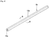
- Fig. 4 is a schematic perspective view of a first embodiment of a balloon tube for use in the present invention.
- the cross section of a balloon tube 8a orthogonal to the axial direction has the shape of a circle on the outside and the shape of a regular triangle on the inside.
- the balloon tube 8a has a cross section that has the shape of a circle on the outside 13a and the shape of a regular triangle on the inside 14a over the entire length of the balloon tube 8a in the axial (longitudinal) direction.
- apex parts of the regular triangle on the inside are located at the same positions in the axial (longitudinal) direction.
- the positions of the apex parts of the regular triangle may be continuously changed in the axial direction to, when the tube is turned into a balloon, form the wing parts in a spiral manner, not in parallel to the axial direction of the balloon.
- Fig. 5 is a cross-sectional view of Fig. 4 taken along B-B line.
- the outer peripheral shape of the cross section on the outside 13a is a circle
- the inner peripheral shape of the cross section on the inside 14a is a regular triangle.
- the regular triangle on the inside 14a is formed such that apex parts 9a contact internally a circumcircle 15a on the inside that is concentric to the center of the circle on the outside 13a. Diameter of the circumcircle 15a can be decided as appropriate taking into account film thickness of the expansion balloon and the like.
- the ratio of a diameter (R1) of the outside circle to a diameter (R2) of the circumcircle is preferably 1.3 or more and 2.8 or less.
- an extrusion die having the shape corresponding to the desired regular-polygonal cross section of the balloon tube can be used for extrusion molding.
- a balloon tube is put on a regular-polygonal core material, a heat-shrinkable tube is put on the balloon tube, and hot wind is applied to the heat-shrinkable tube to contract the balloon tube, thereby to obtain a tube that has the same shape as that of the core material on the inside and has the shape of a circle on the outside.
- the balloon tube is preferably produced by extrusion molding from the viewpoint of simplicity and blow molding yield.
- the balloon tube 8a is placed in a balloon mold, and the balloon tube 8a is stretched in the axial direction and the radial direction by biaxially-stretched blow molding, thereby to produce the desired expansion balloon.
- the shape of the cavity of the balloon mold corresponds to the outer shape of the balloon if the balloon is the balloon 2 having the outer shape shown in Figs. 1 and 2 , for example, that is, if the balloon is a balloon that has the straight pipe part 4 with a columnar outer shape, the taper parts 5a and 5b with an almost conical outer shape, and the sleeve parts 12a and 12b with a columnar outer shape.
- the usable mold has a paired structure that can be opened and closed, for example, such that the paired molds are each provided with a concave portion so that, when being closed, the molds have the shape corresponding to the outer shape of the balloon.
- the expansion rate of the balloon during blow molding is preferably 4 or more and more preferably 6 or less, at a section corresponding to the straight pipe part of the balloon, from the viewpoint of making almost uniform film thickness of the straight pipe part of the balloon.
- the expansion rate is preferably 9 or less and more preferably 8 or less, from the viewpoint of performing stable blow molding.
- the “inner diameter of the balloon mold” here refers to the inner diameter of the cavity corresponding to the straight pipe part of the balloon, and the “inner diameter of the balloon tube” here refers to, in the case of a regular polygon, a circumcircle of the regular polygon.
- Biaxial stretching may be performed under heat condition and may be performed more than once.
- axial stretching may be performed concurrently with radial stretching or may be performed before or after the radial stretching.
- the straight pipe part has the shape of an almost circle on the inside and has an almost uniform film thickness in the circumferential direction.
- the term "almost uniform” in the present invention means that a variation coefficient (standard deviation/average value) is 6.0% or less. This level of variation coefficient exerts no influence on the profile diameter of the balloon when being folded, thereby making it possible to maintain the stable profile diameter.
- the expansion balloon may be subjected to an annealing process to stabilize the shape and dimensions of the expansion balloon.
- a folding shape of the balloon is formed such that the apex parts 9a of the regular triangle shrink to the wing parts and the side parts 10a of the same shrink to a circumcenter (in Fig. 3 , for example, outer surface of the catheter shaft 3b) to form groove parts, and the wing parts and the groove parts extend in the longitudinal direction of the balloon.
- the apex parts 9a form the wing parts and the side parts 10a form the groove parts because, when the balloon tube inflates in the radial direction during blow molding, the foregoing expansion rate on blow molding is different between the apex parts 9a and the side parts 10a.
- the balloon strength and the balloon stretch characteristics vary to exert large influence on the balloon physical properties (molecular orientation, crystallinity degree, and the like). Therefore, the apex parts can form the wing parts and the side parts can form the groove parts due to variations in balloon physical properties resulting from a difference in the expansion rate.
- the cross-sectional structure of the straight pipe part of the obtained expansion balloon is configured such that the cross-sectional parts of the balloon corresponding to the apex parts 9a and the side parts 10a shown in Fig. 5(a) constitute cross-sectional parts different in physical properties shown by reference numerals 16 and 17, respectively, in the schematic view of Fig. 5(b) .
- the cross-sectional parts are alternately formed in the circumferential direction of the balloon and are continuously extended in the longitudinal direction of the balloon, and thus when the balloon is contracted, the wing parts 6 shown in Fig. 3 are prone to be formed at the parts with reference numeral 16 in Fig. 5(b) and the groove parts 7 are prone to be formed at the parts with reference numeral 17 in Fig. 5(b) .
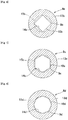
- Figs. 6 to 8 show cross sections of balloon tubes orthogonal to the axial direction in second to fourth embodiments for use in the present invention, respectively.
- the balloon tubes 8b, 8c, and 8d have cross sections that have the shape of a circle on the outside and the shapes of a regular tetragon, a regular hexagon, and a regular octagon on the inside, respectively, over the entire length of the balloon tubes in the axial (longitudinal) direction.
- the positions of the apex parts of the regular polygons may be continuously changed in the axial direction.
- the cross-sectional structures of the straight pipe parts of the obtained expansion balloons are configured such that the cross-sectional parts of the balloons corresponding to the apex parts 9b, 9c, and 9d and the side parts 10b, 10c, and 10d are alternately formed in the circumferential direction of the balloon, and these parts are extended continuously in the longitudinal direction of the balloons, and when balloons are contracted, the wing parts are formed at parts corresponding to the apex parts 9b, 9c, and 9d, and groove parts are formed at parts corresponding to the side parts 10b, 10c, and 10d.
- the balloon tubes 8b, 8c, and 8d that have the cross sections having the shape of a circle on the outsides 13b, 13c, and 13d and having the shapes of a regular tetragon, a regular hexagon, and a regular octagon on the insides 14b, 14c, and 14d can be produced as in the case of the first embodiment shown in Fig. 4 or 5(a) , by using extrusion dies having the shapes corresponding to the desired cross sections of the regular-polygonal balloon tubes.
- these balloon tubes can also be subjected to biaxially-stretched blow molding as in the case of the first embodiment.
- the numbers of wing parts formed vary according to the inside shapes such that three is in the case of a regular triangle, four is in the case of a regular tetragon, three is in the case of a regular hexagon, and four is in the case of a regular octagon, and in the case of polygons with six or more apex parts, there is a tendency that no wing parts identical in number to the apex parts can be obtained. If the sizes of circles formed in the circumcircles of the regular polygons (refer to the parts with reference numerals 15a, 15b, 15c, and 15d in Figs.
- a regular hexagon and a regular octagon provide a number of folds in multiples of 3 or 4, which allows stable folding control, whereas regular polygons not in multiplies of 3 or 4 such as a regular pentagon and a regular heptagon, there is a tendency that stable folding control is difficult.
- the inside of the cross section of the balloon tube orthogonal to the axial direction is preferably formed by a regular polygon in multiplies of 3 or 4. From the viewpoint of reducing the length of the wing parts extending in the radial direction, the number of angles of the regular polygon is preferably four or more.
- the number of wing parts of a regular enneagon is three. This is because two apex parts exist between the wing parts, and not only one of adjacent wing parts but also a wing part next to the adjacent wing parts are taken to form one wing part or apex parts on both sides of an apex part constituting the wing part are taken to form one wing part. If the number of angles of the regular polygon becomes large, the balloon tube is folded in such a manner described above with variations in dimensions of the respective wing parts, and thus there is a tendency that it is difficult to stabilize the profile diameter. Thus, from the viewpoint of stabilizing the profile diameter, the number of angles of the regular polygon on the inside of the cross section is preferably eight or less.
- the inside of the cross section of the balloon tube orthogonal to the axial direction more preferably has the shape of a regular tetragon, a regular hexagon, or a regular octagon.
- the expansion balloon produced by the production method of the present invention is used to expand a narrowed area in a blood vessel by percutaneous luminal surgery including peripheral angioplasty, coronary artery angioplasty, and valvuloplasty.
- percutaneous luminal surgery including peripheral angioplasty, coronary artery angioplasty, and valvuloplasty.
- a balloon catheter is inserted from outside the body and the balloon is advanced to a treatment site, and then the balloon is inflated to expand the narrowed area to restore a blood flow.
- a balloon tube was produced by extrusion molding so as to have a tube cross section with the shape of a circle on the outside and the shape of a regular triangle on the inside as shown in Figs. 4 or 5(a) , by using polyamide elastomer with a durometer hardness of 72D (trade name: PEBAX7233SA01: produced by Arkema KK). Tube dimensions were designed such that the outer diameter of the tube was 0.98 mm, the diameter of a circumcircle (15a) of the regular polygon constituting the inside of the tube was 0.44 mm, and the outside circle and the circumcircle (15a) were concentric to each other.
- the extrusion-molded balloon tube was set into a balloon mold (the inner diameter of the cavity corresponding to the straight pipe part is 3.00 mm) to subject the balloon tube to biaxially-stretched blow molding such that the expansion rate becomes 6.8, thereby producing five expansion balloons in which the diameter of the straight pipe part was 3.00 mm, the length of the straight pipe part was 15 mm, and the lengths of the taper parts at the distal side and the proximal side were both 4 mm.
- a balloon tube was produced by using the same material as that of Example 1 and with the same dimensions as those of Example 1 (outer diameter and diameter of the circumcircle (15b)) so as to have a cross section with the shape of a circle on the outside and the shape of a regular tetragon on the inside as shown in Fig. 6 . Then, five balloons with the same shape as that of Example 1 were produced by the same method as that for Example 1.
- a balloon tube was produced by using the same material as that of Example 1 and with the same dimensions as those of Example 1 (outer diameter and diameter of the circumcircle (15c)) so as to have a cross section with the shape of a circle on the outside and the shape of a regular hexagon on the inside as shown in Fig. 7 . Then, five balloons with the same shape as that of Example 1 were produced by the same method as that for Example 1.
- a balloon tube was produced by using the same material as that of Example 1 and with the same dimensions as those of Example 1 (outer diameter and diameter of the circumcircle (15d)) so as to have a cross section with the shape of a circle on the outside and the shape of a regular octagon on the inside as shown in Fig. 8 . Then, five balloons with the same shape as that of Example 1 were produced by the same method as that for Example 1.
- a balloon tube (not shown) was produced by using the same material as that of Example 1 and with the same dimensions (outer diameter) as those of Example 1 so as to have a cross section with the shape of a circle both on the outside and the inside. Then, five balloons were produced by the same method as that for Example 1. The diameters of the circumcircles in the examples and the diameter of the inside circle of Comparative Example 1 were the same.
- the expansion balloons produced as the examples and the comparative example were expanded for 30 minutes in the water at 37°C under 1.82 Mpa. After that, the balloons were contracted and the numbers of wing parts formed at folding of the balloons were counted.
- film thicknesses of the straight pipe parts of the balloons in the examples were measured at the middle portion and both ends by a micrometer at intervals of 60° in the circumferential direction, and thus the film thicknesses were determined at 18 points. At that time, the thicknesses of the entire balloons were evenly measured with measurement position shifts by 10 to 20° such that the (total three) measurement points at the middle portion and the both ends did not align in a straight line.
- the number of wing parts formed at folding of the balloon was three in Examples 1 and 3 and the number of the same was four in Examples 2 and 4, whereas the number of the same was two in the comparative example.
- the profile diameter could be reduced in all of the examples.
- the numbers of wing parts were the same in all of the (five) samples produced as each of the examples, and thus it has been revealed that the folding shapes were stable in all of the examples.
- the balloon film thicknesses in the examples were at the same level as the comparative example.
- a series of molding processes was simple and molding yields were high significantly.
Landscapes
- Health & Medical Sciences (AREA)
- Engineering & Computer Science (AREA)
- Life Sciences & Earth Sciences (AREA)
- Heart & Thoracic Surgery (AREA)
- Manufacturing & Machinery (AREA)
- Anesthesiology (AREA)
- Biophysics (AREA)
- Pulmonology (AREA)
- Child & Adolescent Psychology (AREA)
- Biomedical Technology (AREA)
- Hematology (AREA)
- Animal Behavior & Ethology (AREA)
- General Health & Medical Sciences (AREA)
- Public Health (AREA)
- Veterinary Medicine (AREA)
- Media Introduction/Drainage Providing Device (AREA)
- Mechanical Engineering (AREA)
Claims (7)
- Herstellungsverfahren für einen Expansionsballon (2) zur Verwendung in einem Ballonkatheter (1), das folgende Schritte aufweist:Erhalten eines Ballonrohres (8), das einen zu einer axialen Richtung senkrechten Querschnitt mit der Form eines Kreises auf der Außenseite (13a bis 13d) und der Form eines Polygons mit einem Umkreis (15a bis 15d) auf der Innenseite (14a bis 14d) hat; undPlatzieren des Ballonrohres (8) in einem Formwerkzeug zum biaxialen Streckblasformen, um den Ballon (2) zu erhalten, dadurch gekennzeichnet, dassdas Formwerkzeug einen Hohlraum aufweist, der der Außenform des Ballons (2) entspricht, der ein gerades Rohrteil (4) mit einer säulenförmigen äußeren Form aufweist.
- Herstellungsverfahren für einen Expansionsballon (2) nach Anspruch 1, wobei das Ballonrohr (8) den Querschnitt mit der Form eines Polygons in Vielfachen von 3 oder 4 auf der Innenseite hat, das einen Umkreis (15a bis 15d) auf der Innenseite hat.
- Herstellungsverfahren für einen Expansionsballon (2) nach Anspruch 1 oder 2, wobei das Ballonrohr (8) den Querschnitt mit der Form eines Polygons mit einem beliebigen Umkreis (15a bis 15d) auf der Innenseite hat, das aus einem Viereck, einem Sechseck und einem Achteck auf der Innenseite ausgewählt ist.
- Herstellungsverfahren für einen Expansionsballon nach einem der Ansprüche 1 bis 3, wobei das Polygon mit einem Umkreis (15a bis 15d) ein regelmäßiges Polygon ist.
- Herstellungsverfahren für einen Expansionsballon (2) nach einem der Ansprüche 1 bis 4, wobei die Außenform und die Innenform des Querschnitts des Ballonrohres (8) über die gesamte Länge in der axialen Richtung ausgebildet sind.
- Herstellungsverfahren für einen Expansionsballon (2) nach einem der Ansprüche 1 bis 5, wobei die Schichtstärke des geraden Rohrteils (4) nahezu gleichmäßig ist.
- Herstellungsverfahren für einen Expansionsballon nach einem der Ansprüche 1 bis 6, wobei eine Expansionsrate des Ballons (2) bei dem biaxialen Streckblasformen 4 oder mehr und 9 oder weniger beträgt.
Applications Claiming Priority (2)
| Application Number | Priority Date | Filing Date | Title |
|---|---|---|---|
| JP2011279010 | 2011-12-20 | ||
| PCT/JP2012/082543 WO2013094541A1 (ja) | 2011-12-20 | 2012-12-14 | 拡張用バルーンの製造方法 |
Publications (3)
| Publication Number | Publication Date |
|---|---|
| EP2796162A1 EP2796162A1 (de) | 2014-10-29 |
| EP2796162A4 EP2796162A4 (de) | 2015-09-23 |
| EP2796162B1 true EP2796162B1 (de) | 2019-05-15 |
Family
ID=48668432
Family Applications (1)
| Application Number | Title | Priority Date | Filing Date |
|---|---|---|---|
| EP12860696.9A Active EP2796162B1 (de) | 2011-12-20 | 2012-12-14 | Herstellungsverfahren für einen expansionsballon |
Country Status (4)
| Country | Link |
|---|---|
| US (1) | US9861796B2 (de) |
| EP (1) | EP2796162B1 (de) |
| JP (1) | JP6264042B2 (de) |
| WO (1) | WO2013094541A1 (de) |
Families Citing this family (5)
| Publication number | Priority date | Publication date | Assignee | Title |
|---|---|---|---|---|
| CN104721943A (zh) * | 2013-12-24 | 2015-06-24 | 微创心脉医疗科技(上海)有限公司 | 球囊、球囊扩张导管和球囊的制作方法及模具 |
| JP6440159B2 (ja) * | 2014-10-08 | 2018-12-19 | 株式会社カネカ | バルーン製造用チューブ、バルーン、およびバルーン製造方法 |
| WO2021053714A1 (ja) * | 2019-09-17 | 2021-03-25 | オリンパス株式会社 | 内視鏡用バルーン処置具 |
| CN111012999B (zh) * | 2019-12-18 | 2024-04-19 | 四川扬子江医疗器械有限公司 | 一种小直径球囊导管及其制造方法 |
| CN114177489B (zh) * | 2021-12-17 | 2024-08-20 | 普利瑞医疗科技(苏州)有限公司 | 一种鼓泡球囊的制备方法 |
Family Cites Families (8)
| Publication number | Priority date | Publication date | Assignee | Title |
|---|---|---|---|---|
| DE69011784D1 (de) | 1989-08-25 | 1994-09-29 | Bard Inc C R | Plissierter Ballondilatationskatheter und Verfahren zur Herstellung. |
| US5195970A (en) | 1991-04-26 | 1993-03-23 | Gahara William J | Collapsible balloon catheters |
| EP1611917B1 (de) * | 1995-10-11 | 2016-04-27 | Terumo Kabushiki Kaisha | Ballon für Katheter und Ballonkatheter |
| JP4761671B2 (ja) | 2001-08-29 | 2011-08-31 | テルモ株式会社 | 形状記憶バルーン、その製造方法およびバルーンカテーテル |
| JP4967258B2 (ja) * | 2004-06-10 | 2012-07-04 | 株式会社カネカ | バルーンおよびバルーンカテーテル |
| US7972351B2 (en) * | 2004-07-13 | 2011-07-05 | Boston Scientific Scimed, Inc. | Balloon folding design and method and apparatus for making balloons |
| WO2006126311A1 (ja) * | 2005-05-27 | 2006-11-30 | Kaneka Corporation | バルーンおよびバルーンカテーテル |
| US8088100B2 (en) * | 2006-10-20 | 2012-01-03 | Boston Scientific Scimed, Inc. | Reinforced rewrappable balloon |
-
2012
- 2012-12-14 US US14/367,091 patent/US9861796B2/en active Active
- 2012-12-14 WO PCT/JP2012/082543 patent/WO2013094541A1/ja active Application Filing
- 2012-12-14 JP JP2013550261A patent/JP6264042B2/ja active Active
- 2012-12-14 EP EP12860696.9A patent/EP2796162B1/de active Active
Non-Patent Citations (1)
| Title |
|---|
| None * |
Also Published As
| Publication number | Publication date |
|---|---|
| US20150021834A1 (en) | 2015-01-22 |
| US9861796B2 (en) | 2018-01-09 |
| WO2013094541A1 (ja) | 2013-06-27 |
| EP2796162A1 (de) | 2014-10-29 |
| JP6264042B2 (ja) | 2018-01-24 |
| JPWO2013094541A1 (ja) | 2015-04-27 |
| EP2796162A4 (de) | 2015-09-23 |
Similar Documents
| Publication | Publication Date | Title |
|---|---|---|
| US6572813B1 (en) | Balloon forming process | |
| US6544224B1 (en) | Lobed balloon catheter and method of use | |
| EP2043722B1 (de) | Ballonkatheter mit grosser festigkeit und flexibilität | |
| US8609016B2 (en) | Refoldable balloon and method of making and using the same | |
| US7691082B2 (en) | Medical devices | |
| US9132259B2 (en) | Multilayer balloon for a catheter | |
| US10201683B2 (en) | Medical balloon including pleats | |
| EP2796162B1 (de) | Herstellungsverfahren für einen expansionsballon | |
| US6863856B1 (en) | Slotted mold for making a catheter balloon | |
| US20090264822A1 (en) | Method of Making a Zero-Fold Balloon With Variable Inflation Volume | |
| US20140277062A1 (en) | Medical balloon having tapered or stepped profile | |
| EP1320400B1 (de) | Verfahren zur herstellung einer medizinischen ballon-vorrichtung | |
| EP2813256B1 (de) | Herstellunsverfahren für einen ballonschlauch | |
| US20090254113A1 (en) | Dilatation balloon with ridges and methods | |
| WO2004067074A1 (en) | Mold for forming medical balloon | |
| EP1625869A1 (de) | Ballonkatheter und verfahren zu seiner herstellung | |
| US20090234282A1 (en) | Outer Catheter Shaft to Balloon Joint | |
| JP6078371B2 (ja) | バルーンカテーテル用バルーンの製造方法 | |
| JP6134154B2 (ja) | バルーンカテーテル用バルーン | |
| JP6440159B2 (ja) | バルーン製造用チューブ、バルーン、およびバルーン製造方法 | |
| JP2004298356A (ja) | 拡張用バルーンおよびこれを備えたバルーンカテーテル | |
| JP2005323714A (ja) | 医療用カテーテルバルーン | |
| JP2009297143A (ja) | 医療用バルーンカテーテル |
Legal Events
| Date | Code | Title | Description |
|---|---|---|---|
| PUAI | Public reference made under article 153(3) epc to a published international application that has entered the european phase |
Free format text: ORIGINAL CODE: 0009012 |
|
| 17P | Request for examination filed |
Effective date: 20140708 |
|
| AK | Designated contracting states |
Kind code of ref document: A1 Designated state(s): AL AT BE BG CH CY CZ DE DK EE ES FI FR GB GR HR HU IE IS IT LI LT LU LV MC MK MT NL NO PL PT RO RS SE SI SK SM TR |
|
| DAX | Request for extension of the european patent (deleted) | ||
| RA4 | Supplementary search report drawn up and despatched (corrected) |
Effective date: 20150821 |
|
| RIC1 | Information provided on ipc code assigned before grant |
Ipc: A61M 25/10 20130101AFI20150817BHEP |
|
| GRAP | Despatch of communication of intention to grant a patent |
Free format text: ORIGINAL CODE: EPIDOSNIGR1 |
|
| STAA | Information on the status of an ep patent application or granted ep patent |
Free format text: STATUS: GRANT OF PATENT IS INTENDED |
|
| INTG | Intention to grant announced |
Effective date: 20181129 |
|
| GRAS | Grant fee paid |
Free format text: ORIGINAL CODE: EPIDOSNIGR3 |
|
| GRAA | (expected) grant |
Free format text: ORIGINAL CODE: 0009210 |
|
| STAA | Information on the status of an ep patent application or granted ep patent |
Free format text: STATUS: THE PATENT HAS BEEN GRANTED |
|
| AK | Designated contracting states |
Kind code of ref document: B1 Designated state(s): AL AT BE BG CH CY CZ DE DK EE ES FI FR GB GR HR HU IE IS IT LI LT LU LV MC MK MT NL NO PL PT RO RS SE SI SK SM TR |
|
| RAP1 | Party data changed (applicant data changed or rights of an application transferred) |
Owner name: KANEKA CORPORATION |
|
| REG | Reference to a national code |
Ref country code: CH Ref legal event code: EP Ref country code: GB Ref legal event code: FG4D |
|
| REG | Reference to a national code |
Ref country code: DE Ref legal event code: R096 Ref document number: 602012060246 Country of ref document: DE |
|
| REG | Reference to a national code |
Ref country code: IE Ref legal event code: FG4D |
|
| REG | Reference to a national code |
Ref country code: NL Ref legal event code: MP Effective date: 20190515 |
|
| REG | Reference to a national code |
Ref country code: LT Ref legal event code: MG4D |
|
| PG25 | Lapsed in a contracting state [announced via postgrant information from national office to epo] |
Ref country code: PT Free format text: LAPSE BECAUSE OF FAILURE TO SUBMIT A TRANSLATION OF THE DESCRIPTION OR TO PAY THE FEE WITHIN THE PRESCRIBED TIME-LIMIT Effective date: 20190915 Ref country code: ES Free format text: LAPSE BECAUSE OF FAILURE TO SUBMIT A TRANSLATION OF THE DESCRIPTION OR TO PAY THE FEE WITHIN THE PRESCRIBED TIME-LIMIT Effective date: 20190515 Ref country code: AL Free format text: LAPSE BECAUSE OF FAILURE TO SUBMIT A TRANSLATION OF THE DESCRIPTION OR TO PAY THE FEE WITHIN THE PRESCRIBED TIME-LIMIT Effective date: 20190515 Ref country code: SE Free format text: LAPSE BECAUSE OF FAILURE TO SUBMIT A TRANSLATION OF THE DESCRIPTION OR TO PAY THE FEE WITHIN THE PRESCRIBED TIME-LIMIT Effective date: 20190515 Ref country code: FI Free format text: LAPSE BECAUSE OF FAILURE TO SUBMIT A TRANSLATION OF THE DESCRIPTION OR TO PAY THE FEE WITHIN THE PRESCRIBED TIME-LIMIT Effective date: 20190515 Ref country code: NO Free format text: LAPSE BECAUSE OF FAILURE TO SUBMIT A TRANSLATION OF THE DESCRIPTION OR TO PAY THE FEE WITHIN THE PRESCRIBED TIME-LIMIT Effective date: 20190815 Ref country code: NL Free format text: LAPSE BECAUSE OF FAILURE TO SUBMIT A TRANSLATION OF THE DESCRIPTION OR TO PAY THE FEE WITHIN THE PRESCRIBED TIME-LIMIT Effective date: 20190515 Ref country code: HR Free format text: LAPSE BECAUSE OF FAILURE TO SUBMIT A TRANSLATION OF THE DESCRIPTION OR TO PAY THE FEE WITHIN THE PRESCRIBED TIME-LIMIT Effective date: 20190515 Ref country code: LT Free format text: LAPSE BECAUSE OF FAILURE TO SUBMIT A TRANSLATION OF THE DESCRIPTION OR TO PAY THE FEE WITHIN THE PRESCRIBED TIME-LIMIT Effective date: 20190515 |
|
| PG25 | Lapsed in a contracting state [announced via postgrant information from national office to epo] |
Ref country code: RS Free format text: LAPSE BECAUSE OF FAILURE TO SUBMIT A TRANSLATION OF THE DESCRIPTION OR TO PAY THE FEE WITHIN THE PRESCRIBED TIME-LIMIT Effective date: 20190515 Ref country code: BG Free format text: LAPSE BECAUSE OF FAILURE TO SUBMIT A TRANSLATION OF THE DESCRIPTION OR TO PAY THE FEE WITHIN THE PRESCRIBED TIME-LIMIT Effective date: 20190815 Ref country code: GR Free format text: LAPSE BECAUSE OF FAILURE TO SUBMIT A TRANSLATION OF THE DESCRIPTION OR TO PAY THE FEE WITHIN THE PRESCRIBED TIME-LIMIT Effective date: 20190816 Ref country code: LV Free format text: LAPSE BECAUSE OF FAILURE TO SUBMIT A TRANSLATION OF THE DESCRIPTION OR TO PAY THE FEE WITHIN THE PRESCRIBED TIME-LIMIT Effective date: 20190515 |
|
| REG | Reference to a national code |
Ref country code: AT Ref legal event code: MK05 Ref document number: 1132715 Country of ref document: AT Kind code of ref document: T Effective date: 20190515 |
|
| PG25 | Lapsed in a contracting state [announced via postgrant information from national office to epo] |
Ref country code: DK Free format text: LAPSE BECAUSE OF FAILURE TO SUBMIT A TRANSLATION OF THE DESCRIPTION OR TO PAY THE FEE WITHIN THE PRESCRIBED TIME-LIMIT Effective date: 20190515 Ref country code: EE Free format text: LAPSE BECAUSE OF FAILURE TO SUBMIT A TRANSLATION OF THE DESCRIPTION OR TO PAY THE FEE WITHIN THE PRESCRIBED TIME-LIMIT Effective date: 20190515 Ref country code: AT Free format text: LAPSE BECAUSE OF FAILURE TO SUBMIT A TRANSLATION OF THE DESCRIPTION OR TO PAY THE FEE WITHIN THE PRESCRIBED TIME-LIMIT Effective date: 20190515 Ref country code: SK Free format text: LAPSE BECAUSE OF FAILURE TO SUBMIT A TRANSLATION OF THE DESCRIPTION OR TO PAY THE FEE WITHIN THE PRESCRIBED TIME-LIMIT Effective date: 20190515 Ref country code: RO Free format text: LAPSE BECAUSE OF FAILURE TO SUBMIT A TRANSLATION OF THE DESCRIPTION OR TO PAY THE FEE WITHIN THE PRESCRIBED TIME-LIMIT Effective date: 20190515 Ref country code: CZ Free format text: LAPSE BECAUSE OF FAILURE TO SUBMIT A TRANSLATION OF THE DESCRIPTION OR TO PAY THE FEE WITHIN THE PRESCRIBED TIME-LIMIT Effective date: 20190515 |
|
| REG | Reference to a national code |
Ref country code: DE Ref legal event code: R097 Ref document number: 602012060246 Country of ref document: DE |
|
| PG25 | Lapsed in a contracting state [announced via postgrant information from national office to epo] |
Ref country code: IT Free format text: LAPSE BECAUSE OF FAILURE TO SUBMIT A TRANSLATION OF THE DESCRIPTION OR TO PAY THE FEE WITHIN THE PRESCRIBED TIME-LIMIT Effective date: 20190515 Ref country code: SM Free format text: LAPSE BECAUSE OF FAILURE TO SUBMIT A TRANSLATION OF THE DESCRIPTION OR TO PAY THE FEE WITHIN THE PRESCRIBED TIME-LIMIT Effective date: 20190515 |
|
| PLBE | No opposition filed within time limit |
Free format text: ORIGINAL CODE: 0009261 |
|
| STAA | Information on the status of an ep patent application or granted ep patent |
Free format text: STATUS: NO OPPOSITION FILED WITHIN TIME LIMIT |
|
| PG25 | Lapsed in a contracting state [announced via postgrant information from national office to epo] |
Ref country code: TR Free format text: LAPSE BECAUSE OF FAILURE TO SUBMIT A TRANSLATION OF THE DESCRIPTION OR TO PAY THE FEE WITHIN THE PRESCRIBED TIME-LIMIT Effective date: 20190515 |
|
| 26N | No opposition filed |
Effective date: 20200218 |
|
| PG25 | Lapsed in a contracting state [announced via postgrant information from national office to epo] |
Ref country code: PL Free format text: LAPSE BECAUSE OF FAILURE TO SUBMIT A TRANSLATION OF THE DESCRIPTION OR TO PAY THE FEE WITHIN THE PRESCRIBED TIME-LIMIT Effective date: 20190515 |
|
| PG25 | Lapsed in a contracting state [announced via postgrant information from national office to epo] |
Ref country code: SI Free format text: LAPSE BECAUSE OF FAILURE TO SUBMIT A TRANSLATION OF THE DESCRIPTION OR TO PAY THE FEE WITHIN THE PRESCRIBED TIME-LIMIT Effective date: 20190515 |
|
| REG | Reference to a national code |
Ref country code: CH Ref legal event code: PL |
|
| REG | Reference to a national code |
Ref country code: BE Ref legal event code: MM Effective date: 20191231 |
|
| PG25 | Lapsed in a contracting state [announced via postgrant information from national office to epo] |
Ref country code: MC Free format text: LAPSE BECAUSE OF FAILURE TO SUBMIT A TRANSLATION OF THE DESCRIPTION OR TO PAY THE FEE WITHIN THE PRESCRIBED TIME-LIMIT Effective date: 20190515 |
|
| GBPC | Gb: european patent ceased through non-payment of renewal fee |
Effective date: 20191214 |
|
| PG25 | Lapsed in a contracting state [announced via postgrant information from national office to epo] |
Ref country code: FR Free format text: LAPSE BECAUSE OF NON-PAYMENT OF DUE FEES Effective date: 20191231 Ref country code: LU Free format text: LAPSE BECAUSE OF NON-PAYMENT OF DUE FEES Effective date: 20191214 Ref country code: GB Free format text: LAPSE BECAUSE OF NON-PAYMENT OF DUE FEES Effective date: 20191214 |
|
| PG25 | Lapsed in a contracting state [announced via postgrant information from national office to epo] |
Ref country code: LI Free format text: LAPSE BECAUSE OF NON-PAYMENT OF DUE FEES Effective date: 20191231 Ref country code: BE Free format text: LAPSE BECAUSE OF NON-PAYMENT OF DUE FEES Effective date: 20191231 Ref country code: CH Free format text: LAPSE BECAUSE OF NON-PAYMENT OF DUE FEES Effective date: 20191231 |
|
| PG25 | Lapsed in a contracting state [announced via postgrant information from national office to epo] |
Ref country code: CY Free format text: LAPSE BECAUSE OF FAILURE TO SUBMIT A TRANSLATION OF THE DESCRIPTION OR TO PAY THE FEE WITHIN THE PRESCRIBED TIME-LIMIT Effective date: 20190515 |
|
| PG25 | Lapsed in a contracting state [announced via postgrant information from national office to epo] |
Ref country code: IS Free format text: LAPSE BECAUSE OF FAILURE TO SUBMIT A TRANSLATION OF THE DESCRIPTION OR TO PAY THE FEE WITHIN THE PRESCRIBED TIME-LIMIT Effective date: 20190915 |
|
| PG25 | Lapsed in a contracting state [announced via postgrant information from national office to epo] |
Ref country code: HU Free format text: LAPSE BECAUSE OF FAILURE TO SUBMIT A TRANSLATION OF THE DESCRIPTION OR TO PAY THE FEE WITHIN THE PRESCRIBED TIME-LIMIT; INVALID AB INITIO Effective date: 20121214 Ref country code: MT Free format text: LAPSE BECAUSE OF FAILURE TO SUBMIT A TRANSLATION OF THE DESCRIPTION OR TO PAY THE FEE WITHIN THE PRESCRIBED TIME-LIMIT Effective date: 20190515 |
|
| PG25 | Lapsed in a contracting state [announced via postgrant information from national office to epo] |
Ref country code: MK Free format text: LAPSE BECAUSE OF FAILURE TO SUBMIT A TRANSLATION OF THE DESCRIPTION OR TO PAY THE FEE WITHIN THE PRESCRIBED TIME-LIMIT Effective date: 20190515 |
|
| PGFP | Annual fee paid to national office [announced via postgrant information from national office to epo] |
Ref country code: IE Payment date: 20231109 Year of fee payment: 12 Ref country code: DE Payment date: 20231031 Year of fee payment: 12 |