EP1625869A1 - Ballonkatheter und verfahren zu seiner herstellung - Google Patents
Ballonkatheter und verfahren zu seiner herstellung Download PDFInfo
- Publication number
- EP1625869A1 EP1625869A1 EP04732819A EP04732819A EP1625869A1 EP 1625869 A1 EP1625869 A1 EP 1625869A1 EP 04732819 A EP04732819 A EP 04732819A EP 04732819 A EP04732819 A EP 04732819A EP 1625869 A1 EP1625869 A1 EP 1625869A1
- Authority
- EP
- European Patent Office
- Prior art keywords
- balloon
- longitudinal axis
- groove
- projection
- taper
- Prior art date
- Legal status (The legal status is an assumption and is not a legal conclusion. Google has not performed a legal analysis and makes no representation as to the accuracy of the status listed.)
- Withdrawn
Links
Images


Classifications
-
- A—HUMAN NECESSITIES
- A61—MEDICAL OR VETERINARY SCIENCE; HYGIENE
- A61M—DEVICES FOR INTRODUCING MEDIA INTO, OR ONTO, THE BODY; DEVICES FOR TRANSDUCING BODY MEDIA OR FOR TAKING MEDIA FROM THE BODY; DEVICES FOR PRODUCING OR ENDING SLEEP OR STUPOR
- A61M25/00—Catheters; Hollow probes
- A61M25/10—Balloon catheters
- A61M25/1027—Making of balloon catheters
- A61M25/1029—Production methods of the balloon members, e.g. blow-moulding, extruding, deposition or by wrapping a plurality of layers of balloon material around a mandril
- A61M2025/1031—Surface processing of balloon members, e.g. coating or deposition; Mounting additional parts onto the balloon member's surface
-
- A—HUMAN NECESSITIES
- A61—MEDICAL OR VETERINARY SCIENCE; HYGIENE
- A61M—DEVICES FOR INTRODUCING MEDIA INTO, OR ONTO, THE BODY; DEVICES FOR TRANSDUCING BODY MEDIA OR FOR TAKING MEDIA FROM THE BODY; DEVICES FOR PRODUCING OR ENDING SLEEP OR STUPOR
- A61M25/00—Catheters; Hollow probes
- A61M25/10—Balloon catheters
- A61M2025/1043—Balloon catheters with special features or adapted for special applications
- A61M2025/1086—Balloon catheters with special features or adapted for special applications having a special balloon surface topography, e.g. pores, protuberances, spikes or grooves
-
- A—HUMAN NECESSITIES
- A61—MEDICAL OR VETERINARY SCIENCE; HYGIENE
- A61M—DEVICES FOR INTRODUCING MEDIA INTO, OR ONTO, THE BODY; DEVICES FOR TRANSDUCING BODY MEDIA OR FOR TAKING MEDIA FROM THE BODY; DEVICES FOR PRODUCING OR ENDING SLEEP OR STUPOR
- A61M25/00—Catheters; Hollow probes
- A61M25/10—Balloon catheters
- A61M25/1027—Making of balloon catheters
- A61M25/1038—Wrapping or folding devices for use with balloon catheters
Definitions
- the present invention relates to a balloon catheter used in percutaneous angioplasty (e.g., percutaneous transluminal angioplasty (PTA) or percutaneous transluminal coronary angioplasty (PTCA)) for dilating and treating stenosed or occluded coronary arteries, arteries of extremities, renal arteries, peripheral blood vessels, or the like.
- PTA percutaneous transluminal angioplasty
- PTCA percutaneous transluminal coronary angioplasty
- the present invention also relates to a method for producing a balloon and the balloon catheter.
- Balloon catheters used in PTA or PTCA treatment each have a balloon at the distal end of a shaft and each are mostly composed of a flexible resin.
- a guiding catheter is inserted from a femoral artery through an aorta, and then the tip of the guiding catheter is positioned at the entrance of a coronary artery.
- a guidewire is allowed to pass through a stenosed or occluded lesion in the coronary artery or the like.
- a balloon catheter is inserted along the guidewire. The balloon is placed at the lesion.
- a contrast medium or the like is introduced into the balloon to inflate the balloon. After dilation treatment of the lesion, the balloon is deflated by decompression, and the dilation catheter is removed from the body.
- balloon catheters have been required to be applicable to the highly stenosed, bent, and difficult lesions of blood vessels; and be capable of smoothly transferring balloons to lesions.
- the balloons and regions near the balloons have been softened.
- the shapes of balloons have been imparted by folding or the like.
- the balloon be deflated and automatically folded around the catheter shaft to reduce its size.
- various methods for imparting a shape of a balloon have been proposed.
- Japanese Unexamined Patent Application Publication No. 62-114565 discloses a method of folding a balloon along a single folding line in the longitudinal axis and then winding the folded balloon in four layers around a catheter shaft.
- Japanese Unexamined Patent Application Publication No. 3-92173 discloses a method of controlling folding by the difference of rigidity due to wall thickenss distribution on a balloon.
- PCT Japanese Translation Patent Publication No. 9-512190 discloses a method for imparting a shape of a balloon by disposing a cylindrical balloon in a moldbeing in the form of a regular tetragon in cross section and then heating the balloon while stretching.
- Japanese Unexamined Patent Application Publication No. 2003-62080 discloses a method for imparting a shape of a balloon by forming a plurality of continuous grooves at least in the direction of the longitudinal axis and wings corresponding to the grooves using a die in advance, the grooves and wings corresponding to a scroll cross-section having grooves and projections, the number of wings being the same as that of the grooves.
- Japanese Unexamined Patent Application Publication No. 2002-263193 discloses a balloon having at least one flat face at a balloon taper or a projection and/or a groove at a balloon taper.
- a catheter in the form of a plate including the longitudinal axis of the catheter (winging state.
- the length of a wing in the directionperpendicular to the longitudinal axis is larger than the diameter of a balloon being inflated, thus increasing resistance in removing the balloon from the body.
- a normal blood vessel or the like may be damaged or a plurality of wings are projected.
- it is disadvantageously difficult to reduce the diameter. Therefore, in a known balloon catheter, it is difficult to provide a balloon catheter having desired recrossability.
- the present invention provides a balloon catheter having satisfactory recrossability.
- a medical balloon catheter according to the present invention includes a balloon having a groove and/or a projection helically provided on the balloon relative to the longitudinal axis of the balloon.
- the groove and/or the projection are helically provided on at least one balloon taper relative to the longitudinal axis of the balloon. According to this structure, for example, when the balloon is pushed into or removed through a difficult-to-pass area, such as a stenosed area, it is possible to more effectively reduce resistance.
- a mold is preferably used in producing the balloon of the balloon catheter. Thereby, a balloon catheter can be easily produced in high yield and with stable quality.
- a medical balloon catheter according to the present invention includes a balloon having a groove and/or a projection helicallyprovided relative to the longitudinal axis of the balloon.
- a groove and/or a projection helically provided on a balloon relative to the longitudinal axis, even if the balloon undergoes plastic deformation during inflation, it is assumed that since the balloon catheter can generate winding force that allows the balloon to be wound around the axis, high recrossability can be achieved.
- a groove and/or a projection are helically provided relative to the longitudinal axis.
- the groove and/or the projection are helically provided on at least one balloon taper relative to the longitudinal axis of the balloon.
- a difficult-to-pass area such as a stenosed area
- the groove and/or the projection are helically provided on a distal balloon taper, having a great effect in pushing the balloon, relative to the longitudinal axis of the balloon.
- the groove and/or the projection helically provided on a balloon taper relative to the longitudinal axis of the balloon are continuously provided at an angle ranging from 15° to 180° when viewed from the distal end, the angle being defined by a starting point and an ending point relative to the central axis (see Figs. 6 and 8).
- the balloon is easily folded.
- the balloon can be easily wound more tightly. Therefore, pushing or removing resistance can be further reduced.
- the groove and/or the projection are provided on the distal balloon taper, the groove and/or the projection extending from the distal end to the proximal side.
- the balloon when the balloon is pushed into a severely stenosed lesion having a diameter smaller than that of the deflated balloon, the balloon can be easily wound more tightly. Therefore, pushing resistance can be further reduced (crossability at a severely stenosed lesion can be maximized).
- a plurality of grooves and/or projections are preferably provided so that the diameter can be reduced when the balloon is deflated.
- the number of grooves and/or projections is preferably 2 to 5 from the standpoint of the degree of efficiency and ease of production (when the number of grooves and/or projections is increased, it becomes difficult to produce the balloon).
- the width of the groove and/or projection is preferably 1 ⁇ m or more, more preferably 10 to 1,000 ⁇ m, and most preferably 10 to 250 ⁇ m.
- the balloon bursts because of stress concentration.
- the resulting balloon has a nonuniform wall thickenss. In this way, the production of the balloon is adversely affected.
- the effect of the present invention on recrossability at a stenosed lesion after the balloon is inflated once is reduced.
- the burst pressure of the balloon may be affected.
- the depth of the groove and/or the height of the projection is preferably 0.01 mm or more and more preferably 0.1 mm to 3.0 mm. At a depth and/or height exceeding 3.0 mm, the diameter may be increased when the balloon is folded.
- the length of the groove and/or projection is preferably 0.1 mm to 4 mm.
- the balloon having a groove and/or a projection helically provided relative to the longitudinal axis of the balloon is preferablyproduced using a mold, by laser heating, or the like. According to these methods, time and cost can be saved. Furthermore, a balloon catheter having the following properties can be produced: for example, when the balloon catheter is pushed into or removed from a severely stenosed lesion having a diameter smaller than that of the deflated balloon, even after inflating the balloon once, the balloon can be easily wound more tightly, and pushing or removing resistance is reduced.
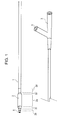
- Figs. 1, 2, and 5 are each an appearance view showing a balloon catheter having a balloon according to an embodiment of the present invention.
- Fig. 3 is an enlarged view of the balloon catheter.
- the balloon 2 of the balloon catheter includes a distal sleeve 2b, a distal balloon taper 2c, a cylindrical midportion 2a, a proximal balloon taper 2c', and a proximal sleeve 2b'.
- Helical grooves 9 helically disposed relative to the longitudinal axis of the balloon are provided on the distal taper 2c.
- Fig. 1 shows an over-the-wire structure
- Fig. 2 shows a monorail structure.
- Each of these shafts usually includes an inflation lumen 4 and a guidewire lumen 6.
- a double-tube structure in which a guidewire tube 7 including the guidewire lumen 6 is inserted and coaxially disposed in an inflation tube 8 including the inflation lumen 4 may be used.
- a structure in which the inflation lumen 4 and the guidewire lumen 6 are not coaxially disposed may be used (Fig. 4).
- Various structures other than these may be used for the shaft of the balloon catheter according to the present invention within the scope of the gist of the present invention.
- the base of the shaft may be composed of a relatively hard material at the proximal side.
- the material include metals such as Ni-Ti, stainless steel (SUS), brass, aluminum or an alloy thereof; and resins having relatively high rigidity, for example, polyimides, polycarbonates, polyamides, and poly(vinyl chlorides).
- the material used at the distal side include polystyrenes, polyolefins, polyesters, polyamides, polyurethanes, polypropylenes, and polyvinyl chlorides; elastomers of these polymers; and mixtures containing a plurality of these polymer.
- the shaft maybe formed of a laminated tube composed of these materials.
- Fig. 6 is a schematic front view of the balloon catheter when viewed from the distal end.
- Each of the grooves 9 is helically, continuously provided relative to the longitudinal axis of the balloon from the distal end to the proximal side of the distal balloon taper 2c.
- Fig. 7 is a schematic front view of a balloon catheter according to an embodiment of the present invention when viewed from the distal end.
- Each projection 10 is helically, continuously provided relative to the longitudinal axis of the balloon from the distal end to the proximal side of the distal balloon taper 2c.
- Fig. 8 is a schematic front view of a balloon catheter according to an embodiment of the present invention when viewed from the distal end.
- grooves and/orproj ections need not be provided on the entire distal balloon taper 2c in the direction of the longitudinal axis. If the grooves or projections provided on the distal balloon taper from the distal end to the proximal side interfere with the assembly of the catheter, the grooves or projections may be partially provided on the taper. However, to achieve high recrossability, the grooves or projections are preferably provided on the entire distal balloon taper in the direction of the longitudinal axis.
- the lengths, widths, and depths (heights) of the grooves and/or projections may be the same or different.
- the grooves or projections may have any shape. However, from the standpoint of the difficulty of fabrication and cost, the shapes are preferably the same and linear.
- a method for forming the grooves and/or projections helicallyprovided relative to the longitudinal axis of the balloon a method in which the grooves and/or projections are formed simultaneously with the formation of the balloon may be employed.
- the groove and/or projection may be formed separately.
- the following method for forming the groove and/or projection may be applied: a method in which a mold is used in balloon blowing, a dipping method, or a method in which physical energy such as a laser is used.
- any of various methods other than these methods may be employed for forming the groove and/or projection.
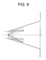
- a method of using a mold in balloon blowing is preferable.
- An example of a mold used for forming a balloon having a groove and/or a projection is shown in Fig. 9 (perspective side view of a taper) and Fig. 10 (perspective view of the taper and the sleeve). This mold is used for producing a balloon, as shown in Fig. 8, having the grooves 9 that are not entirely provided on the balloon taper 2c across the longitudinal direction.
- the groove and/or the projection may be formed by applying thermal energy to a balloon that has already been formed or by irradiating the balloon with a laser. In this case, it is not necessary to produce a mold having a complex shape. Furthermore, the degree of freedom of the choice of the shape of the helical groove and/or projection is high.
- the maximum outer diameter of the cylindrical midportion 2a in inflating the balloon is preferably about 1 mm to 20 mm and more preferably about 1 to 10 mm.
- the length of the cylindrical midportion of the balloon is preferably about 5.0 mm to 70 mm and more preferably about 10 mm to 50 mm.
- the total length of the balloon is preferably about 10 to 100 mm and more preferably about 15 mm to 70 mm.
- the wall thickenss of the balloon is preferably about 5 ⁇ m to 80 ⁇ m and more preferably about 10 ⁇ m to 50 ⁇ m.
- the wall thickenss may be substantially uniform or may be nonuniform.
- the balloon is preferably composed of a material having a certain degree of plasticity so as to dilate a stenosed lesion.
- the material include polyolefins, polyolefin elastomers, polyesters, polyester elastomers, polyamides, polyamide elastomers, polyurethane, polyurethane elastomers, fluorocarbon resins, ionomers, and latex rubbers. Furthermore, a mixture or a laminated material of these may be used. It is understood that a material containing fillers such as metal particles or plastic fibers may be used.
- Reference numeral 1 represents a shaft
- reference numeral 2 represents a balloon
- reference numeral 2a represents the cylindrical midportion of the balloon
- reference numeral 2b represents the distal sleeve of the balloon
- reference numeral 2b' represents the proximal sleeve of the balloon
- reference numeral 2c represents the distal taper of the balloon
- reference numeral 2c' represents the proximal taper of the balloon
- reference numeral 3 represents a manifold
- reference numeral 4 represents an inflation lumen
- reference numeral 5 represents an inflation port
- reference numeral 6 represents a guidewire lumen
- reference numeral 7 represents a guidewire tube
- reference numeral 8 represents a inflation tube
- reference numeral 9 represents a groove
- reference numeral 10 represents a projection
- ⁇ represents an angle defined by a starting point and an ending point of the groove and/or the projection provided on the balloon taper relative to the central axis (Figs. 6 and 8).
- a tubular parison (inner diameter: 0.43 mm, oute rdiameter: 0.89 mm) was produced by extrusion molding with a polyamide elastomer (trade name: PEBAX7233SA01, manufactured by Elf Atochem, Inc.).
- a balloon having an external diameter of 3.0 mm at the cylindrical midportion was produced by biaxial stretching blow forming with the resulting parison using a balloonmold capable of forming grooves as shown in Fig. 6.
- the grooves were provided from the distal end of the distal balloon taper to the proximal side.
- the number of grooves was four.
- the grooves each had a width of 200 ⁇ m and a depth of 100 ⁇ m. ⁇ was 60°.
- a guidewire tube (inner diameter: 0.42mm, outer diameter: 0.56 mm) and an inflation tube (inner diameter: 0.71 mm, outer diameter: 0.88 mm), which were used as tubes at the distal side of the shaft base and were composed of a polyamide elastomer (trade name: PEBAX7233SA01, manufactured by Elf Atochem, Inc.), were produced by extrusion molding.
- These tubes and a tube (inner diameter: 0.50 mm, outer diameter: 0.66 mm), which was used as a tube at the proximal side of the shaft base, composed of SUS316 stainless steel were used to produce a coaxial-type monorail balloon catheter.
- a balloon catheter was produced as in Example 1, except that a balloon mold capable of forming helical grooves from the distal end of the distal balloon taper to the intermediate portion of the distal balloon taper, as shown in Fig. 8, was used.
- the number of grooves was four.
- the grooves each had a width of 200 ⁇ m and a depth of 100 ⁇ m or less. ⁇ was 60°.
- a balloon catheter was produced using a balloon mold as in Examples 1 and 2, except that the helical grooves were not provided on the balloon.
- the balloon catheters produced in Examples 1 and 2 and Comparative example were evaluated by the following method.
- a simulated aorta and a guiding catheter were set in a vessel filled with physiological saline at 37°C.
- the tip of the guiding catheter was connected to a simulated small-diameter tube 1.50 mm in inner diameter composed of polyethylene, the tube simulating the stenosed lesion of a coronary artery.
- a balloon catheter was inserted in the guiding catheter with a guidewire in advance.
- the guidewire was disposed so as to protrude 100 mm from the distal end of the balloon catheter.
- a mixture of a contrast medium and physiological saline was introduced into the balloon catheter to 14 atm with an indef lator, and the inflated balloon was maintained for 30 seconds. Then, the balloon was deflated rapidly.
- a balloon catheter according to the present invention has grooves and/or projections helically provided relative to the longitudinal axis of the balloon, even after inflating the balloon once, for example, when the balloon is pushed into or removed from a severely stenosed lesion having a diameter smaller than that of the deflated balloon, the balloon can be easily wound more tightly. Therefore, pushing or removing resistance can be reduced.
- a balloon can be easily produced using a mold in high yield and with stable quality.
- a laser by irradiating a balloon with a laser, it is not necessary to produce a mold having a complex shape.
- the degree of freedom of the choice of the shape of the helical groove and/or projection is high.
Landscapes
- Health & Medical Sciences (AREA)
- Heart & Thoracic Surgery (AREA)
- Life Sciences & Earth Sciences (AREA)
- Engineering & Computer Science (AREA)
- Anesthesiology (AREA)
- Child & Adolescent Psychology (AREA)
- Biophysics (AREA)
- Pulmonology (AREA)
- Biomedical Technology (AREA)
- Hematology (AREA)
- Animal Behavior & Ethology (AREA)
- General Health & Medical Sciences (AREA)
- Public Health (AREA)
- Veterinary Medicine (AREA)
- Manufacturing & Machinery (AREA)
- Media Introduction/Drainage Providing Device (AREA)
Applications Claiming Priority (2)
| Application Number | Priority Date | Filing Date | Title |
|---|---|---|---|
| JP2003141213 | 2003-05-19 | ||
| PCT/JP2004/006817 WO2004101057A1 (ja) | 2003-05-19 | 2004-05-13 | バルーンカテーテル及びバルーンカテーテルの製造方法 |
Publications (2)
| Publication Number | Publication Date |
|---|---|
| EP1625869A1 true EP1625869A1 (de) | 2006-02-15 |
| EP1625869A4 EP1625869A4 (de) | 2007-03-14 |
Family
ID=33447433
Family Applications (1)
| Application Number | Title | Priority Date | Filing Date |
|---|---|---|---|
| EP04732819A Withdrawn EP1625869A4 (de) | 2003-05-19 | 2004-05-13 | Ballonkatheter und verfahren zu seiner herstellung |
Country Status (7)
| Country | Link |
|---|---|
| US (1) | US20060276820A1 (de) |
| EP (1) | EP1625869A4 (de) |
| JP (1) | JPWO2004101057A1 (de) |
| KR (1) | KR20060010744A (de) |
| CN (1) | CN1780658A (de) |
| CA (1) | CA2523985A1 (de) |
| WO (1) | WO2004101057A1 (de) |
Cited By (1)
| Publication number | Priority date | Publication date | Assignee | Title |
|---|---|---|---|---|
| US7306616B2 (en) | 2003-05-05 | 2007-12-11 | Boston Scientific Scimed, Inc. | Balloon catheter and method of making same |
Families Citing this family (11)
| Publication number | Priority date | Publication date | Assignee | Title |
|---|---|---|---|---|
| US20060182873A1 (en) * | 2005-02-17 | 2006-08-17 | Klisch Leo M | Medical devices |
| ATE446116T1 (de) * | 2005-08-19 | 2009-11-15 | Abbott Lab Vascular Entpr Ltd | Verfahren zur herstellung eines ballons eines ballonkatheters und ballon |
| CN101730563B (zh) * | 2007-03-27 | 2012-12-26 | 因特拉泰克医药有限公司 | 螺旋囊体导管 |
| US8025636B2 (en) * | 2007-05-02 | 2011-09-27 | Boston Scientific Scimed, Inc. | Balloon catheters |
| CN101785900B (zh) * | 2010-03-10 | 2013-01-02 | 成都维德医疗器械有限责任公司 | 一种药物球囊导管的制备方法 |
| WO2013134437A1 (en) * | 2012-03-06 | 2013-09-12 | Futurematrix Interventional, Inc. | Medical balloon with enhanced refolding properties |
| US20150127043A1 (en) * | 2013-11-07 | 2015-05-07 | Medtronic Vascular, Inc. | Balloon Catheter Having a Pre-Positioned Refold Tool |
| EP3157613B1 (de) * | 2014-06-17 | 2018-08-29 | Covidien LP | Medizinischer ballon mit rillen |
| CN110478601B (zh) * | 2019-08-28 | 2022-06-07 | 赛诺神畅医疗科技有限公司 | 球囊导管 |
| WO2021053714A1 (ja) * | 2019-09-17 | 2021-03-25 | オリンパス株式会社 | 内視鏡用バルーン処置具 |
| EP4268881A1 (de) * | 2020-12-24 | 2023-11-01 | Kaneka Corporation | Ballon für ballonkatheter |
Citations (4)
| Publication number | Priority date | Publication date | Assignee | Title |
|---|---|---|---|---|
| US5041125A (en) * | 1989-01-26 | 1991-08-20 | Cordis Corporation | Balloon catheter |
| EP0485903A2 (de) * | 1990-11-10 | 1992-05-20 | Terumo Kabushiki Kaisha | Ballon für Katheter, mit dem Ballon ausgerüsteter Katheterballon und Verfahren zur Herstellung des Ballons |
| EP0783897A2 (de) * | 1996-01-11 | 1997-07-16 | Schneider (Usa) Inc. | Laserablation eines Angioplastiekatheters und Ballon |
| US5853389A (en) * | 1996-03-07 | 1998-12-29 | Cordis Corporation | Balloon catheter and method for manufacturing |
Family Cites Families (4)
| Publication number | Priority date | Publication date | Assignee | Title |
|---|---|---|---|---|
| US5545132A (en) * | 1993-12-21 | 1996-08-13 | C. R. Bard, Inc. | Helically grooved balloon for dilatation catheter and method of using |
| NL9500468A (nl) * | 1995-03-08 | 1996-10-01 | Cordis Europ | Balloncatheter en werkwijze voor het vervaardigen daarvan. |
| FR2753907B1 (fr) * | 1996-10-02 | 1999-07-16 | Nycomed Lab Sa | Ballon pour catheter de dilatation et son procede de fabrication |
| JP4782297B2 (ja) * | 2001-03-09 | 2011-09-28 | 川澄化学工業株式会社 | カテーテル用バルーン及びバルーンカテーテル |
-
2004
- 2004-05-13 CA CA002523985A patent/CA2523985A1/en not_active Abandoned
- 2004-05-13 CN CNA2004800115334A patent/CN1780658A/zh active Pending
- 2004-05-13 EP EP04732819A patent/EP1625869A4/de not_active Withdrawn
- 2004-05-13 US US10/552,289 patent/US20060276820A1/en not_active Abandoned
- 2004-05-13 JP JP2005506251A patent/JPWO2004101057A1/ja active Pending
- 2004-05-13 WO PCT/JP2004/006817 patent/WO2004101057A1/ja not_active Application Discontinuation
- 2004-05-13 KR KR1020057019210A patent/KR20060010744A/ko not_active Application Discontinuation
Patent Citations (4)
| Publication number | Priority date | Publication date | Assignee | Title |
|---|---|---|---|---|
| US5041125A (en) * | 1989-01-26 | 1991-08-20 | Cordis Corporation | Balloon catheter |
| EP0485903A2 (de) * | 1990-11-10 | 1992-05-20 | Terumo Kabushiki Kaisha | Ballon für Katheter, mit dem Ballon ausgerüsteter Katheterballon und Verfahren zur Herstellung des Ballons |
| EP0783897A2 (de) * | 1996-01-11 | 1997-07-16 | Schneider (Usa) Inc. | Laserablation eines Angioplastiekatheters und Ballon |
| US5853389A (en) * | 1996-03-07 | 1998-12-29 | Cordis Corporation | Balloon catheter and method for manufacturing |
Non-Patent Citations (1)
| Title |
|---|
| See also references of WO2004101057A1 * |
Cited By (1)
| Publication number | Priority date | Publication date | Assignee | Title |
|---|---|---|---|---|
| US7306616B2 (en) | 2003-05-05 | 2007-12-11 | Boston Scientific Scimed, Inc. | Balloon catheter and method of making same |
Also Published As
| Publication number | Publication date |
|---|---|
| CN1780658A (zh) | 2006-05-31 |
| JPWO2004101057A1 (ja) | 2006-07-13 |
| CA2523985A1 (en) | 2004-11-25 |
| EP1625869A4 (de) | 2007-03-14 |
| WO2004101057A1 (ja) | 2004-11-25 |
| KR20060010744A (ko) | 2006-02-02 |
| US20060276820A1 (en) | 2006-12-07 |
Similar Documents
| Publication | Publication Date | Title |
|---|---|---|
| EP2043722B1 (de) | Ballonkatheter mit grosser festigkeit und flexibilität | |
| US5163989A (en) | Method for forming a balloon mold and the use of such mold | |
| EP1051990B1 (de) | Ballonkatheter sowie Herstellungsverfahren | |
| US6849062B2 (en) | Catheter having a low-friction guidewire lumen and method of manufacture | |
| EP1233793B1 (de) | Medizinische ballon-vorrichtung | |
| US9095689B2 (en) | Non-compliant multilayered balloon for a catheter | |
| US7972351B2 (en) | Balloon folding design and method and apparatus for making balloons | |
| US20080125707A1 (en) | Balloon catheter shaft having high strength and flexibility and method of making same | |
| US6863856B1 (en) | Slotted mold for making a catheter balloon | |
| WO2001085229A2 (en) | Lobed balloon catheter and method of use | |
| WO2002041934A2 (en) | Balloon blowing process with metered volumetric inflation for producing a baloon catherer | |
| EP1625869A1 (de) | Ballonkatheter und verfahren zu seiner herstellung | |
| EP1601401A1 (de) | Form zum bilden eines medizinischen ballons | |
| EP2796162B1 (de) | Herstellungsverfahren für einen expansionsballon | |
| US6712833B1 (en) | Method of making a catheter balloon | |
| JP4815657B2 (ja) | 医療用ポリマーブレンド材料およびこの材料を用いた医療用バルーン | |
| US20020171180A1 (en) | Method of making a catheter balloon | |
| JP2005323714A (ja) | 医療用カテーテルバルーン | |
| JP2001314512A (ja) | 均一膜厚バルーンおよびバルーンカテーテル | |
| JP2003144553A (ja) | バルーンおよびバルーンカテーテル | |
| JP2006129978A (ja) | カテーテルバルーンの製造方法 |
Legal Events
| Date | Code | Title | Description |
|---|---|---|---|
| PUAI | Public reference made under article 153(3) epc to a published international application that has entered the european phase |
Free format text: ORIGINAL CODE: 0009012 |
|
| 17P | Request for examination filed |
Effective date: 20051010 |
|
| AK | Designated contracting states |
Kind code of ref document: A1 Designated state(s): AT BE BG CH CY CZ DE DK EE ES FI FR GB GR HU IE IT LI LU MC NL PL PT RO SE SI SK TR |
|
| DAX | Request for extension of the european patent (deleted) | ||
| A4 | Supplementary search report drawn up and despatched |
Effective date: 20070214 |
|
| 17Q | First examination report despatched |
Effective date: 20070522 |
|
| STAA | Information on the status of an ep patent application or granted ep patent |
Free format text: STATUS: THE APPLICATION IS DEEMED TO BE WITHDRAWN |
|
| 18D | Application deemed to be withdrawn |
Effective date: 20071002 |