EP2813256B1 - Herstellunsverfahren für einen ballonschlauch - Google Patents
Herstellunsverfahren für einen ballonschlauch Download PDFInfo
- Publication number
- EP2813256B1 EP2813256B1 EP13746450.9A EP13746450A EP2813256B1 EP 2813256 B1 EP2813256 B1 EP 2813256B1 EP 13746450 A EP13746450 A EP 13746450A EP 2813256 B1 EP2813256 B1 EP 2813256B1
- Authority
- EP
- European Patent Office
- Prior art keywords
- balloon
- drawability
- tube
- highest
- parts
- Prior art date
- Legal status (The legal status is an assumption and is not a legal conclusion. Google has not performed a legal analysis and makes no representation as to the accuracy of the status listed.)
- Active
Links
Images



Classifications
-
- A—HUMAN NECESSITIES
- A61—MEDICAL OR VETERINARY SCIENCE; HYGIENE
- A61M—DEVICES FOR INTRODUCING MEDIA INTO, OR ONTO, THE BODY; DEVICES FOR TRANSDUCING BODY MEDIA OR FOR TAKING MEDIA FROM THE BODY; DEVICES FOR PRODUCING OR ENDING SLEEP OR STUPOR
- A61M25/00—Catheters; Hollow probes
- A61M25/10—Balloon catheters
- A61M25/104—Balloon catheters used for angioplasty
-
- A—HUMAN NECESSITIES
- A61—MEDICAL OR VETERINARY SCIENCE; HYGIENE
- A61M—DEVICES FOR INTRODUCING MEDIA INTO, OR ONTO, THE BODY; DEVICES FOR TRANSDUCING BODY MEDIA OR FOR TAKING MEDIA FROM THE BODY; DEVICES FOR PRODUCING OR ENDING SLEEP OR STUPOR
- A61M25/00—Catheters; Hollow probes
- A61M25/10—Balloon catheters
- A61M25/1002—Balloon catheters characterised by balloon shape
-
- A—HUMAN NECESSITIES
- A61—MEDICAL OR VETERINARY SCIENCE; HYGIENE
- A61M—DEVICES FOR INTRODUCING MEDIA INTO, OR ONTO, THE BODY; DEVICES FOR TRANSDUCING BODY MEDIA OR FOR TAKING MEDIA FROM THE BODY; DEVICES FOR PRODUCING OR ENDING SLEEP OR STUPOR
- A61M25/00—Catheters; Hollow probes
- A61M25/10—Balloon catheters
- A61M25/1027—Making of balloon catheters
- A61M25/1029—Production methods of the balloon members, e.g. blow-moulding, extruding, deposition or by wrapping a plurality of layers of balloon material around a mandril
-
- B—PERFORMING OPERATIONS; TRANSPORTING
- B29—WORKING OF PLASTICS; WORKING OF SUBSTANCES IN A PLASTIC STATE IN GENERAL
- B29C—SHAPING OR JOINING OF PLASTICS; SHAPING OF MATERIAL IN A PLASTIC STATE, NOT OTHERWISE PROVIDED FOR; AFTER-TREATMENT OF THE SHAPED PRODUCTS, e.g. REPAIRING
- B29C55/00—Shaping by stretching, e.g. drawing through a die; Apparatus therefor
- B29C55/22—Shaping by stretching, e.g. drawing through a die; Apparatus therefor of tubes
- B29C55/26—Shaping by stretching, e.g. drawing through a die; Apparatus therefor of tubes biaxial
-
- A—HUMAN NECESSITIES
- A61—MEDICAL OR VETERINARY SCIENCE; HYGIENE
- A61M—DEVICES FOR INTRODUCING MEDIA INTO, OR ONTO, THE BODY; DEVICES FOR TRANSDUCING BODY MEDIA OR FOR TAKING MEDIA FROM THE BODY; DEVICES FOR PRODUCING OR ENDING SLEEP OR STUPOR
- A61M25/00—Catheters; Hollow probes
- A61M25/10—Balloon catheters
- A61M2025/1043—Balloon catheters with special features or adapted for special applications
- A61M2025/1059—Balloon catheters with special features or adapted for special applications having different inflatable sections mainly depending on the response to the inflation pressure, e.g. due to different material properties
-
- A—HUMAN NECESSITIES
- A61—MEDICAL OR VETERINARY SCIENCE; HYGIENE
- A61M—DEVICES FOR INTRODUCING MEDIA INTO, OR ONTO, THE BODY; DEVICES FOR TRANSDUCING BODY MEDIA OR FOR TAKING MEDIA FROM THE BODY; DEVICES FOR PRODUCING OR ENDING SLEEP OR STUPOR
- A61M25/00—Catheters; Hollow probes
- A61M25/10—Balloon catheters
- A61M2025/1043—Balloon catheters with special features or adapted for special applications
- A61M2025/1081—Balloon catheters with special features or adapted for special applications having sheaths or the like for covering the balloon but not forming a permanent part of the balloon, e.g. retractable, dissolvable or tearable sheaths
-
- A—HUMAN NECESSITIES
- A61—MEDICAL OR VETERINARY SCIENCE; HYGIENE
- A61M—DEVICES FOR INTRODUCING MEDIA INTO, OR ONTO, THE BODY; DEVICES FOR TRANSDUCING BODY MEDIA OR FOR TAKING MEDIA FROM THE BODY; DEVICES FOR PRODUCING OR ENDING SLEEP OR STUPOR
- A61M25/00—Catheters; Hollow probes
- A61M25/10—Balloon catheters
- A61M2025/1043—Balloon catheters with special features or adapted for special applications
- A61M2025/1086—Balloon catheters with special features or adapted for special applications having a special balloon surface topography, e.g. pores, protuberances, spikes or grooves
-
- B—PERFORMING OPERATIONS; TRANSPORTING
- B29—WORKING OF PLASTICS; WORKING OF SUBSTANCES IN A PLASTIC STATE IN GENERAL
- B29K—INDEXING SCHEME ASSOCIATED WITH SUBCLASSES B29B, B29C OR B29D, RELATING TO MOULDING MATERIALS OR TO MATERIALS FOR MOULDS, REINFORCEMENTS, FILLERS OR PREFORMED PARTS, e.g. INSERTS
- B29K2101/00—Use of unspecified macromolecular compounds as moulding material
- B29K2101/12—Thermoplastic materials
-
- B—PERFORMING OPERATIONS; TRANSPORTING
- B29—WORKING OF PLASTICS; WORKING OF SUBSTANCES IN A PLASTIC STATE IN GENERAL
- B29K—INDEXING SCHEME ASSOCIATED WITH SUBCLASSES B29B, B29C OR B29D, RELATING TO MOULDING MATERIALS OR TO MATERIALS FOR MOULDS, REINFORCEMENTS, FILLERS OR PREFORMED PARTS, e.g. INSERTS
- B29K2105/00—Condition, form or state of moulded material or of the material to be shaped
- B29K2105/25—Solid
- B29K2105/253—Preform
-
- B—PERFORMING OPERATIONS; TRANSPORTING
- B29—WORKING OF PLASTICS; WORKING OF SUBSTANCES IN A PLASTIC STATE IN GENERAL
- B29L—INDEXING SCHEME ASSOCIATED WITH SUBCLASS B29C, RELATING TO PARTICULAR ARTICLES
- B29L2031/00—Other particular articles
- B29L2031/753—Medical equipment; Accessories therefor
- B29L2031/7542—Catheters
- B29L2031/7543—Balloon catheters
-
- F—MECHANICAL ENGINEERING; LIGHTING; HEATING; WEAPONS; BLASTING
- F04—POSITIVE - DISPLACEMENT MACHINES FOR LIQUIDS; PUMPS FOR LIQUIDS OR ELASTIC FLUIDS
- F04C—ROTARY-PISTON, OR OSCILLATING-PISTON, POSITIVE-DISPLACEMENT MACHINES FOR LIQUIDS; ROTARY-PISTON, OR OSCILLATING-PISTON, POSITIVE-DISPLACEMENT PUMPS
- F04C2270/00—Control; Monitoring or safety arrangements
- F04C2270/04—Force
- F04C2270/041—Controlled or regulated
Definitions
- the present invention relates to a balloon tube fabrication method.
- Percutaneous angioplasty such as PTA (Percutaneous Transluminal Angioplasty) or PTCA (Percutaneous Transluminal Coronary Angioplasty) is a therapy in which a narrow part or an occluded part generated in a vascular lumen is removed, and a procedure for recovering or improving blood flow in a coronary artery or a peripheral blood vessel.
- PTA Percutaneous Transluminal Angioplasty
- PTCA Percutaneous Transluminal Coronary Angioplasty
- catheters formed of a medical tube are used.
- the catheter is advanced while a route (blood vessel) is selected, until it reached a narrow part to be treated.
- a route blood vessel
- a pointed end of the catheter passes through a narrow part and a balloon, which is disposed around the pointed end, dilates the narrow part.
- This balloon has desirably a physical property in which it is easily folded to a small diameter in order to improve pass characteristic until a narrow part to be treated, and for this end, a thinner film thickness is better.
- the pressure resistance of the balloon is enhanced by providing a uniform and above certain film thickness to the balloon, in order to improve an expansive force of the balloon at the narrow part.
- the film thickness of the balloon is thinner, however, a balloon having a partially extremely thin (that is, ununiform) film thickness, because of excessive pursuit of thinness, has a deteriorated pressure resistance.
- JP 2008-23270 A discloses a blow-molding method in which a tube, which has been drawn in an axial direction while a balloon part is left, is mounted on a balloon metal mold when a balloon tube is formed.
- US 5 087 394 A discloses a method for forming an inflatable catheter balloon from an initial length of tubing which includes longitudinally stretching a first end segment of the tubing element and longitudinally stretching a second end segment of the tubing element. The longitudinally stretched tubing is then heated, blow-molded to radially stretch it and define a desired inflatable portion for the balloon, and cooled.
- WO 95/08965 relates to a prosthesis delivery system having a balloon catheter with an inflatable balloon on its exterior.
- the balloon is inflatable by injection of fluid through a lumen in the catheter and the balloon is initially partially constrained against inflation by a constraint.
- a tubular prosthesis is initially disposed on the catheter in the contracted condition.
- a balloon catheter includes a constraint so that the balloon may be sequentially inflated for dilation purposes such as in a valvuloplasty operation.
- JP 2008-23270 A does not consider a temperature distribution in a metal mold used in the blow-molding. As a result, if the temperature distribution of the metal mold deviates from a desired temperature distribution, the balloon tube is expanded in an unwanted way (for example, a starting point of the drawing in the balloon tube deviates from a desired position when blow-molding is performed), and thus, it is difficult to form a balloon having a uniform film thickness.
- the present invention has been made in order to solve the problems described above.
- the object of the invention is to provide a fabrication method of a balloon tube, which is preferable for stably fabricating a balloon having a uniform film thickness.
- the balloon tube is processed after it is mounted on a mold.
- a balloon tube includes a bag part.
- a plurality of parts having a different drawability in a radial direction is disposed in an axial direction of the balloon tube.
- the highest drawability part which is a part having the highest drawability is disposed to separate from both ends of the bag part in the axial direction of the balloon tube.
- the highest drawability part preferably has the thickest film thickness in the bag part.
- a sleeve formed from a film having a film thickness thinner than the film thickness of the bag part may be disposed adjacent to at least one side of the bag part in the axial direction of the balloon tube.
- the highest drawability part may have a cut in its surface.
- the highest drawability part may be subjected to a chemical processing for increasing the drawability.
- Both of a balloon fabricated from the balloon tube described above and a balloon catheter including such a balloon can be also the result of the present invention.
- a fabrication method of a balloon tube which is processed after it is mounted on a mold including the following steps of a first heating step in which two first parts which are separated from each other in an axial direction of a tube material, which is a base of the balloon tube; a first drawing step in which at least one end of the tube material is drawn to form the highest drawability part at which the drawability is the highest between the two first parts; a second heating step in which, in the tube material, two second parts, which are separated from each other so that all of the plurality of the heated positions of the first parts are sandwiched between them, are heated ; and a second drawing step in which at least one end of the tube material is drawn to form a bag part having the highest drawability part disposed between the two second parts.
- a balloon having a uniform film thickness can be stably fabricated.
- Fig. 5 is a perspective view showing a balloon catheter 40, which is one kind of the catheters; and Fig. 6 is a side view showing a balloon 30 taking up from the balloon catheter 40.
- the balloon 30 is disposed at one end of a catheter shaft 41, and, on the other hand, a hub 42 is disposed at the other end of the catheter shaft 41.
- the balloon 30 dilates a blood vessel, which is blocked due to stenotic lesion (such as a thrombus), to secure blood flow.
- a balloon 30 is a tubular member (a hollow member), and is disposed at one side of the balloon catheter 40.
- a tubular part around the center of the balloon 30 is referred to as a main tube part 31.
- a tubular part which is between the main tube part 31 and the capillary part 33, and is tapered off toward the both ends of the balloon 30 is referred to as a taper part 32.
- a side where the balloon 30 is disposed is referred to as a distal side and a side opposite to the distal side is referred to as a proximal side.
- a side in each member it may sometimes be referred to as a distal side or a proximal side.
- the end of the distal side is referred to as a distal end and a part in the vicinity of the distal end is referred to as a distal end part; and the end of the proximal side is referred to as a proximal end and a part in the vicinity of the proximal end is referred to as a proximal end part.
- the balloon 30 is explained in detailed.
- the balloon 30 is preferably fabricated by blow-molding (for example, biaxially drawing blow-molding) a balloon tube 10, as shown in, for example, Fig. 1 which is the side view and Fig. 2 which is the cross-sectional view, in a state in which it is housed in an interior space (a cavity) of a metal mold [a mold] for balloon-molding.
- the balloon tube 10 is a hollow member (a tubular member) and includes a bag part 14.
- Sleeves 13, which are hollow members, are connected to both sides of the bag part 14 (a hollow part in the bag part 14 and a hollow part of the sleeve 13 flow through each other).
- a plurality of parts is disposed along an axial direction X of the balloon tube 10. More specifically, on the bag part 14, a plurality of parts having a different drawability in a radial direction centered around an axial direction X, are disposed along the axial direction X.
- the "drawability in the radial direction" shows a level of easiness of drawing in the radial direction of the balloon tube 10 upon the blow-molding, and means, for example, that a part having a high drawability is more easily drawn (more easily blown) in the radial direction than a part having a low drawability, in a constant blowing pressure.
- a drawing direction of a film forming the balloon tube 10 can be defined by an axial direction X and a circumferential direction of the balloon tube 10.
- the highest drawability part 11 which is a part having the highest drawability, is disposed to separate from both ends 15 and 15 of the bag part 14 (both ends of the bag part 14 in the axial direction X). More specifically, the highest drawability part 11 is disposed in a middle of the balloon tube 10, and side end parts 12 [a part of the bag part 14 excluding the highest drawability part 11] are disposed adjacent to the both sides of the highest drawability part 11 (the side end parts 12 and 12 have a drawability in the radial direction lower than that of the highest drawability part 11).
- the difference in the drawability between the highest drawability part 11 and the side end part 12 is based on the difference in the film thickness (wall thickness) of the parts 11 and 12 in the example of this drawing. More specifically, as shown in Fig. 2 , the film thickness T1 of the highest drawability part 11 is thicker than the film thickness T2 of the side end part 12. The film thickness T2 of the side end part 12 is thicker than the film thickness T3 of the sleeve 13 (i.e., a relationship of T1>T2>T3 is satisfied).
- blow-molding is performed as shown in Fig. 3A to Fig. 3E to provide a balloon 30.
- the balloon tube 10 is put in a metal mold 50 having a cavity 51, and then one end of one of the sleeves 13 included in the balloon tube 10 is sealed with a clip 54 (for example, one end of the sleeve 13, exposing from the metal mold 50, is sealed with the clip 54).
- the metal mold 50 is heated at a desired temperature.
- the balloon tube 10 is drawn (for example, it is drawn so as to separate the two sleeves 13 and 13 from each other; see a white arrow).
- the highest drawability part 11 is expanded while it is elongated in the radial direction by the injection of the fluid.
- the highest drawability part 11 is brought into contact with an inner wall of the metal mold 50, as shown in Fig. 3B , to regulate the drawing in the radial direction (i.e., the highest drawability part 11 in the balloon tube 10 does not become larger than the cavity 51).
- the injection of the fluid to the balloon tube 10 is, however, still continued after that and thus the highest drawability part 11 is expanded while it is elongated in the axial direction X, as shown in Fig. 3C .
- the highest drawability part 11 is elongated from the vicinity of the center to the side end parts 12 and 12, and at the same time the elongated parts is elongated in the radial direction, thus resulting in that the highest drawability part 11 is elongated in the axial direction X and expanded in the radial direction.
- the side end parts 12 and 12 disposed adjacent to the highest drawability part 11 are also elongated in the axial direction X and are expanded in the radial direction, as shown in Fig. 3D (the side end parts 12 of the balloon tube 10, of course, do not become larger than the cavity 51, as in the case of the highest drawability part 11).
- the balloon tube 10 When the injection of the fluid into the balloon tube 10 is continued, the balloon tube 10 is expanded along the shape of the cavity 51, as shown in Fig. 3E . After the balloon tube 10 is formed into a balloon 30 having a desired shape, the metal mold 50 is cooled. After that, unnecessary parts of the sleeve 13 are cut off, and the balloon 30 which is attached to a catheter shaft 41 as shown in Fig. 6 is completed.
- the drawing starts from the highest drawability part 11 as shown in Fig. 3B .
- high quality balloon 30 is stably fabricated, without excessive need of an advanced operation on the fabrication, for example, an improvement of the precision of the metal mold, a suppression of disturbance caused by an outdoor temperature, or a suppression of variation in resin materials.
- the bag part 14 is disposed at the vicinity of the center of the balloon tube 10, and there is difference in the film thickness between the highest drawability part 11 and the side end part 12 of the bag part 14.
- the present invention is not limited thereto.
- the highest drawability part of the balloon tube may be subjected to a chemical processing for increasing the drawability, or cuts may be formed into the surface of the highest drawability part.
- the chemical processing may include, for example, a processing for adjusting a molecular orientation in an axial direction of a resin forming the balloon tube, or a processing for changing properties of a resin forming the balloon tube such as coating a chemical agent capable of changing the drawability of a resin.
- the case in which the highest drawability part is subjected to the chemical processing for increasing the drawability includes a case in which both of the side end parts of the highest drawability part is subjected to a chemical processing for decreasing the drawability, regardless of whether or not the highest drawability part is subjected to the chemical processing.
- the "cut” formed into the surface of the highest drawability part may include, for example, depressions having a fine width formed into the surface of the highest drawability part.
- the structure of the depression can be appropriately decided, considering the drawability.
- Examples of the chemical processing for increasing the drawability of the highest drawability part of the balloon tube may include, for example, a processing of adjusting a molecular orientation in an axial direction of a resin forming the balloon tube.
- the adjustment of the degree of molecular orientation in the axial direction of the resin forming the balloon tube 10 controls so that the vicinity of the center of the balloon tube 10 serves as the starting point of the drawing when the blow-molding is performed.
- the balloon tube 10 i.e., the sleeves 13 in the balloon tube 10 and the vicinity of the center and other parts in the bag part 14 (a part of the bag part 14 adjacent to the sleeves 13), formed by an extrusion molding, have a molecular orientation drawn in an axial direction.
- the molecular orientation in the axial direction is relaxed and the drawability of a desired part is increased.
- the annealing can control so that the vicinity of the center of the balloon tube 10 serves as the starting point of the drawing in the fabrication of the balloon 30 by blow-molding (The drawing amount of each part in the balloon tube 10 may be changed by means other than the annealing).
- coating with a solvent for increasing the drawability may be performed before the blow-molding to soften the resin at the vicinity of the center of the bag part 14, or, conversely, coating with a solvent for decreasing the drawability may be performed to make a resin at parts other than the vicinity of the center of the bag part 14 difficult to be drawn.
- the structure in which depressions having a fine width are formed into the surface may include, for example, a fine groove formed into the surface of the highest drawability part by leaser light and the like. It is needless to say that the processing into grooves by the laser light is a fine groove which does not affect the pressure resistance of the balloon 30.
- the structure of the fine groove may include single or multiple linear grooves in parallel to an axial direction, single or multiple grooves continued linearly in a circumferential direction, grooves in the combination of the two structures described above, and the like.
- the grooves of the combination of the two structures may include latticed grooves which are intersected with a right angle or an angle other than the right angle.
- the depth of the groove is not particularly limited, so long as the pressure resistance of the balloon 30 is not affected, as described above.
- the depth may be from 0.8 to 1.6 ⁇ m.
- the width of the groove is not particularly limited, so long as the drawability and the uniformity of the balloon film thickness are not affected.
- the maximum width may be from 0 to 3 ⁇ m. The maximum width of 0 ⁇ m refers to a state in which the groove is brought into contact with both wall parts.
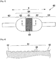
- Fig. 7 is a side view schematically showing a balloon tube 60 having the highest drawability part 61 into which cuts are formed into the surface of the middle part of the bag part 64; and Fig. 8 is a partially enlarged cross-sectional view of Fig. 7 in an I-I direction.
- the balloon tube 60 shown in Figs. 7 and 8 is a hollow member (a tubular member) and includes a bag part 64.
- sleeves 63 which are hollow members, are connected to both sides of this bag part 14 (a hollow part in the bag part 64 and a hollow part of the sleeve 63 flow through each other).
- side end parts 62 are disposed adjacent to both sides of the highest drawability part 61 along the axial direction X of the balloon tube 60.
- the film thickness of the bag part 64 is made thicker than the film thickness of the sleeve 63.
- latticed grooves 66 which are formed of multiple straight lines intersecting perpendicularly to each other, are formed.
- Two straight lines (diagonal lines), which is formed by connecting opposed apexes of each quadrate forming the lattice, are lines in a direction parallel to the axial direction X of the balloon tube 60 and lines in a direction perpendicular to the axial direction X.
- the resin forming the balloon tube 10 (60) is not particularly limited. Examples thereof may include polyolefins such as polyethylene and polypropylene, polyamide, polyurethane, polyester, polyolefin elastomers, polyamide elastomers, polyurethane elastomers, polyester elastomers, and the like. They may be used alone or multiple resins thereof may be used. Of these resins, the polyamide elastomer is particularly preferable, because it has a high pressure resistance and flexibility capable of realizing good blood vessel pass characteristic.
- the balloon tube 10 is fabricated based on a tube material 20.
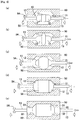
- the balloon tube 10 is fabricated through steps as shown in Fig. 4A to Fig. 4E .
- the tube material refers to a material having a cylindrical structure.
- the example shown in Fig.4 shows an example in which a balloon tube having the structure shown in Figs.1 and 2 is fabricated.
- holding parts are provided at both ends of the tube material 20 in order to draw the tube material 20, but they are omitted in the drawings and explanations described below.
- the tube material 20 is first prepared. Then, as shown in Fig. 4B , first parts P1 and P1, which are separated from each other, are heated in the tube material 20 [a first heating step].
- the first part P1 is, for example, a circumference part (a ring part) in the tube material 20.
- the heating is performed, for example, by using a heater 25.
- the heating temperature is preferably a temperature higher than a glass transition temperature of a resin forming the tubular material.
- the both ends of the tube material 20 are drawn [a first drawing step].
- the tube material 20 is drawn as described above (see white arrows)
- the first parts P1 and P1, which are heated, and parts from the first parts P1 and P1 to the both ends of the tube material 20 are elongated, while the film thickness of a part between P1 and P1 is almost maintained.
- the film thickness of the elongated parts is thinner than the film thickness of the part 21 between the first parts P1 and P1.
- the part shown by the sign 21 will become the highest drawability part.
- the material may be drawn while it is heated. For example, it could be considered that when a width (La2) of the first part P1 is larger than the heater 25, in order to maintain the heating state, the material is drawn with heating while the heater 25 is moved.
- two second parts P2 and P2 which are separated from each other so that the all heated positions of the first parts P1 and P1 (for example, the two positions of the heaters 25 in Fig. 4C ) are sandwiched between them, are heated [a second heating step].
- the second part P2 is a circumference part of the tube material 20, as the first part P1, and the like.
- the heating is performed, for example, by using the heater 25).
- the heating temperature is preferably a temperature higher than a glass transition temperature of a resin forming the tubular material.
- the both ends of the tube material 20 are drawn [a second drawing step].
- the second parts P2 and P2 which are heated, and parts from the second parts P2 and P2 to the both ends of the tube material 20 are elongated, while the film thickness of a part between P2 and P2 is almost maintained.
- the film thickness of the elongated parts is thinner than the film thickness of the parts between the second parts P2 and P2 (in particular, the parts shown by the sign 22 on the both sides of the part shown by the sign 21).
- the part 21, which will become the highest drawability part is turned to the highest drawability part 11, and the parts shown by the sign 22 on the both ends of the part 21, which will become the highest drawability part, are turned to the side end parts 12, whereby the bag part 14 formed of the highest drawability part 11 and the side end parts 12 and 12 are formed.
- sleeves 13 and 13 are formed on the both ends of the bag part 14, and finally the balloon tube 10 as shown in Fig. 2 is completed.
- the drawing may be performed while the material is heated.
- the both ends of the tube material 20 are simultaneously drawn, but the present invention is not limited thereto. It is possible to draw one end and then to draw the other end. In addition, only one end of the both ends of the tube material 20 may be drawn (In a word, it is enough that at least one of the both ends of the tube material 20 is drawn). When only the one end is drawn, it is better that the side, which is not drawn, of the tube material may be held. In this case, for example, the holding may be performed by inserting a core material from the other end side.
- the tube material 20 described above is prepared. Then, two part which are separated from each other on the middle part of the tube material 20 are heated. Next, for example, the both ends of the tube material 20 are drawn to produce a tube material having a bag part and sleeves adjacent to the bag part.
- a part separated from the both ends of the bag part which will become the highest drawability part, is subjected to a desired chemical processing, or cuts are formed into the part, thereby obtaining the balloon tube of the present invention. It is better to adopt, for example, the chemical processing or the cutting method described above.
- the elastomer was extrusion molded into a tube having an outer diameter of 1.3 mm and an inner diameter of 0.7 mm in a case of fabricating a balloon, described below, having an outer diameter ⁇ of 4 mm, or the elastomer was extrusion molded into a tube having an outer diameter of 1.6 mm and an inner diameter of 1.0 mm in a case of fabricating a balloon having an outer diameter ⁇ of 6 mm, thereby obtaining a tube material.
- a balloon tube was fabricated in accordance with the method shown in Fig. 4 .
- Parts La1, La2, and La3 of the tube material correspond to those of the tube material described in Fig. 4B , and the lengths thereof are as shown in Table 1.
- both ends of the tube material were drawn while they were heated to form a part which will become the highest drawability part between the first parts (the sign 21 in Fig. 4C ) (a first drawing step).
- Example 1 or 2 Using the balloon tube of Example 1 or 2, a balloon having an outer diameter (an outer diameter of the part shown by the sign 31 in Fig. 3E ) and a full length (a full length in the axial direction of the parts shown by the signs 31 to 33 in Fig. 3E ), which are shown in Table 1, was fabricated by blow-molding in accordance with the method shown in Fig. 3 .
- the blow-molding conditions follow a usual manner.
- the balloon which was obtained by blow-molding the balloon tube of Example 1 or 2, had a uniform film thickness.
- the balloon tube of the present invention accordingly, is preferable for stably fabricating a balloon having a uniform film thickness.
- Example 1 1.3 0.7 2 3 80 2 4 150 1.0 1.3 1.9 4 20
- Example 2 1.6 1.0 2 3.5 80 2 5 150 1.0 1.4 1.9 6 25
Landscapes
- Health & Medical Sciences (AREA)
- Heart & Thoracic Surgery (AREA)
- Life Sciences & Earth Sciences (AREA)
- Engineering & Computer Science (AREA)
- Anesthesiology (AREA)
- Veterinary Medicine (AREA)
- Biophysics (AREA)
- Pulmonology (AREA)
- Child & Adolescent Psychology (AREA)
- Biomedical Technology (AREA)
- Hematology (AREA)
- Animal Behavior & Ethology (AREA)
- General Health & Medical Sciences (AREA)
- Public Health (AREA)
- Manufacturing & Machinery (AREA)
- Vascular Medicine (AREA)
- Mechanical Engineering (AREA)
- Media Introduction/Drainage Providing Device (AREA)
Claims (3)
- Herstellungsverfahren für einen Ballonschlauch (10; 60), der verarbeitet wird, nachdem er an einer Form montiert ist, das Folgendes aufweist:einen ersten Erwärmungsschritt, in dem zwei erste Teile (P1, P1) erwärmt werden, die voneinander in einer axialen Richtung (X) eines Schlauchmaterials (20) beabstandet sind, das eine Basis des Ballonschlauchs (10; 60) ist;einen ersten Ziehschritt, in dem zumindest ein Ende des Schlauchmaterials (20) gezogen wird, um den am höchsten ziehbaren Teil (11; 61) auszubilden, an dem die Ziehfähigkeit die Höchste zwischen den zwei ersten Teilen (P1, P1) ist;dadurch gekennzeichnet, dassdas Herstellungsverfahren ferner Folgendes aufweist einen zweiten Erwärmungsschritt, in dem in dem Schlauchmaterial (20) zwei zweite Teile (P2, P2) erwärmt werden, die voneinander derart getrennt sind, dass alle von der Vielzahl von erwärmten Positionen der ersten Teile (P1, P1) zwischen diesen liegen; undeinen zweiten Ziehschritt, in dem zumindest ein Ende des Schlauchmaterials (20) gezogen wird, um einen Beutelteil (14; 64) mit dem am höchsten ziehbaren Teil (11; 61) auszubilden, der zwischen den zwei zweiten Teilen (P2, P2) angeordnet ist.
- Herstellungsverfahren eines Ballonschlauchs (10; 60) nach Anspruch 1, wobei in dem zweiten Ziehschritt Buchsen (13; 63) benachbart zu beiden Seiten des Beutelteils (14; 64) ausgebildet werden.
- Herstellungsverfahren eines Ballonschlauchs (10; 60) nach Anspruch 2, der die folgende Formel (1) erfüllt:
 La1: der kürzeste Abstand zwischen den ersten Teilen (P1, P1) in dem Schlauchmaterial (20) vor dem ersten Erwärmungsschritt;La2: eine volle Länge von einem von den ersten Teilen (P1, P1) in der axialen Richtung (X) des Schlauchmaterials (20) vor dem ersten Erwärmungsschritt;La3: der kürzeste Abstand von einem Ende des Schlauchmaterials (20) zu dem ersten Teil;Lb1: eine volle Länge des am höchsten ziehbaren Teils (11; 61) in der axialen Richtung (X) des Ballonschlauchs (10; 60) nach dem zweiten Ziehschritt;Lb2: der kürzeste Abstand von einem Ende des Beutelteils (14; 64) zu dem am höchsten ziehbaren Teil (11; 61) in der axialen Richtung (X) des Ballonschlauchs (10; 60) nach dem zweiten Ziehschritt; undLb3: eine volle Länge der Buchse (13; 63) benachbart zu einer Seite des Beutelteils (14; 64) nach dem zweiten Ziehschritt.
Applications Claiming Priority (2)
| Application Number | Priority Date | Filing Date | Title |
|---|---|---|---|
| JP2012026490 | 2012-02-09 | ||
| PCT/JP2013/052828 WO2013118807A1 (ja) | 2012-02-09 | 2013-02-07 | バルーン用チューブ、バルーン、バルーンカテーテル、および、バルーン用チューブの製造方法 |
Publications (3)
| Publication Number | Publication Date |
|---|---|
| EP2813256A1 EP2813256A1 (de) | 2014-12-17 |
| EP2813256A4 EP2813256A4 (de) | 2015-09-16 |
| EP2813256B1 true EP2813256B1 (de) | 2018-08-22 |
Family
ID=48947564
Family Applications (1)
| Application Number | Title | Priority Date | Filing Date |
|---|---|---|---|
| EP13746450.9A Active EP2813256B1 (de) | 2012-02-09 | 2013-02-07 | Herstellunsverfahren für einen ballonschlauch |
Country Status (4)
| Country | Link |
|---|---|
| US (1) | US9867968B2 (de) |
| EP (1) | EP2813256B1 (de) |
| JP (1) | JP6260281B2 (de) |
| WO (1) | WO2013118807A1 (de) |
Families Citing this family (9)
| Publication number | Priority date | Publication date | Assignee | Title |
|---|---|---|---|---|
| GB201405700D0 (en) * | 2014-03-31 | 2014-05-14 | Smiths Medical Int Ltd | Medico-surgical tubes,cuffs and their manufacture |
| WO2015200532A1 (en) | 2014-06-24 | 2015-12-30 | Edwards Lifesciences Corporation | Peripheral antegrade perfusion and occlusion device |
| US10792477B2 (en) * | 2016-02-08 | 2020-10-06 | Orbusneich Medical Pte. Ltd. | Drug eluting balloon |
| WO2018181323A1 (ja) * | 2017-03-31 | 2018-10-04 | 日本ゼオン株式会社 | パリソン製造方法およびパリソン製造装置 |
| WO2018180491A1 (ja) * | 2017-03-31 | 2018-10-04 | 日本ゼオン株式会社 | パリソン製造方法およびパリソン製造装置 |
| CN109568773B (zh) * | 2018-10-10 | 2021-06-08 | 杭州尤易信息科技有限公司 | 一种球囊及其制作方法 |
| JP7808100B2 (ja) * | 2021-05-10 | 2026-01-28 | 株式会社カネカ | バルーンカテーテル用バルーン及びバルーンカテーテルの製造方法 |
| JP2023183917A (ja) * | 2022-06-17 | 2023-12-28 | 株式会社カネカ | バルーンカテーテル用バルーンの製造方法 |
| USD1095828S1 (en) | 2022-10-07 | 2025-09-30 | Edwards Lifesciences Corporation | Catheter clamping device |
Family Cites Families (13)
| Publication number | Priority date | Publication date | Assignee | Title |
|---|---|---|---|---|
| US4820349A (en) * | 1987-08-21 | 1989-04-11 | C. R. Bard, Inc. | Dilatation catheter with collapsible outer diameter |
| US4963313A (en) * | 1987-11-30 | 1990-10-16 | Boston Scientific Corporation | Balloon catheter |
| US5087394A (en) * | 1989-11-09 | 1992-02-11 | Scimed Life Systems, Inc. | Method for forming an inflatable balloon for use in a catheter |
| US5254091A (en) * | 1991-01-08 | 1993-10-19 | Applied Medical Resources Corporation | Low profile balloon catheter and method for making same |
| US5545209A (en) * | 1993-09-30 | 1996-08-13 | Texas Petrodet, Inc. | Controlled deployment of a medical device |
| US5470313A (en) * | 1994-02-24 | 1995-11-28 | Cardiovascular Dynamics, Inc. | Variable diameter balloon dilatation catheter |
| JP3549254B2 (ja) * | 1994-07-28 | 2004-08-04 | 富士システムズ株式会社 | 医療用バルーンカテーテル |
| US5749851A (en) * | 1995-03-02 | 1998-05-12 | Scimed Life Systems, Inc. | Stent installation method using balloon catheter having stepped compliance curve |
| US6733513B2 (en) * | 1999-11-04 | 2004-05-11 | Advanced Bioprosthetic Surfaces, Ltd. | Balloon catheter having metal balloon and method of making same |
| US9180620B2 (en) * | 2003-08-21 | 2015-11-10 | Boston Scientific Scimed, Inc. | Medical balloons |
| US20050228428A1 (en) * | 2004-04-07 | 2005-10-13 | Afsar Ali | Balloon catheters and methods for manufacturing balloons for balloon catheters |
| JP4752657B2 (ja) | 2006-07-25 | 2011-08-17 | ニプロ株式会社 | カテーテル用バルーンおよびその製造方法 |
| JP2010201007A (ja) * | 2009-03-04 | 2010-09-16 | Sumitomo Bakelite Co Ltd | バルーンカテーテル |
-
2013
- 2013-02-07 JP JP2013557561A patent/JP6260281B2/ja active Active
- 2013-02-07 EP EP13746450.9A patent/EP2813256B1/de active Active
- 2013-02-07 WO PCT/JP2013/052828 patent/WO2013118807A1/ja not_active Ceased
- 2013-02-07 US US14/373,763 patent/US9867968B2/en active Active
Non-Patent Citations (1)
| Title |
|---|
| None * |
Also Published As
| Publication number | Publication date |
|---|---|
| US20150018866A1 (en) | 2015-01-15 |
| WO2013118807A1 (ja) | 2013-08-15 |
| JP6260281B2 (ja) | 2018-01-17 |
| US9867968B2 (en) | 2018-01-16 |
| JPWO2013118807A1 (ja) | 2015-05-11 |
| EP2813256A1 (de) | 2014-12-17 |
| EP2813256A4 (de) | 2015-09-16 |
Similar Documents
| Publication | Publication Date | Title |
|---|---|---|
| EP2813256A1 (de) | Ballonschlauch, ballon, ballonkatheter und herstellungsverfahren für den ballonschlauch | |
| EP2474336B1 (de) | Hochfester und hochflexibler Ballonkatheterschaft und Herstellungsverfahren | |
| US6620128B1 (en) | Balloon blowing process with metered volumetric inflation | |
| EP0318919B1 (de) | Ballonkatheter | |
| US8703260B2 (en) | Catheter balloon and method for forming same | |
| US6863861B1 (en) | Process for forming a medical device balloon | |
| JPH06506848A (ja) | 収縮可能なバルーン・カテーテル | |
| WO2000002613A1 (en) | Method for reducing dilatation balloon cone stiffness | |
| JP2003010338A (ja) | 多層高強度バルーンの製造方法 | |
| EP0937482A2 (de) | Ballon mit dünnen Kegeln hergestellt mit einer ein aussergewöhnliches Design aufweisenden Form | |
| JPH05192408A (ja) | 膨張バルーン製造方法 | |
| EP2796162B1 (de) | Herstellungsverfahren für einen expansionsballon | |
| US9402983B1 (en) | Variably expanding balloon catheter | |
| US20060175739A1 (en) | Hybrid balloon mold and method of using the mold to form a balloon that is used to manufacture a medical dilatation catheter | |
| WO2015146259A1 (ja) | バルーンカテーテル、およびバルーンの製造方法 | |
| JP6078371B2 (ja) | バルーンカテーテル用バルーンの製造方法 | |
| JP6134154B2 (ja) | バルーンカテーテル用バルーン |
Legal Events
| Date | Code | Title | Description |
|---|---|---|---|
| PUAI | Public reference made under article 153(3) epc to a published international application that has entered the european phase |
Free format text: ORIGINAL CODE: 0009012 |
|
| 17P | Request for examination filed |
Effective date: 20140721 |
|
| AK | Designated contracting states |
Kind code of ref document: A1 Designated state(s): AL AT BE BG CH CY CZ DE DK EE ES FI FR GB GR HR HU IE IS IT LI LT LU LV MC MK MT NL NO PL PT RO RS SE SI SK SM TR |
|
| AX | Request for extension of the european patent |
Extension state: BA ME |
|
| DAX | Request for extension of the european patent (deleted) | ||
| RA4 | Supplementary search report drawn up and despatched (corrected) |
Effective date: 20150819 |
|
| RIC1 | Information provided on ipc code assigned before grant |
Ipc: A61M 25/10 20130101AFI20150813BHEP Ipc: B29C 49/08 20060101ALI20150813BHEP Ipc: B29C 55/26 20060101ALI20150813BHEP Ipc: B29K 101/12 20060101ALI20150813BHEP Ipc: B29K 105/00 20060101ALI20150813BHEP Ipc: B29L 31/00 20060101ALI20150813BHEP |
|
| GRAP | Despatch of communication of intention to grant a patent |
Free format text: ORIGINAL CODE: EPIDOSNIGR1 |
|
| STAA | Information on the status of an ep patent application or granted ep patent |
Free format text: STATUS: GRANT OF PATENT IS INTENDED |
|
| INTG | Intention to grant announced |
Effective date: 20180314 |
|
| GRAS | Grant fee paid |
Free format text: ORIGINAL CODE: EPIDOSNIGR3 |
|
| GRAA | (expected) grant |
Free format text: ORIGINAL CODE: 0009210 |
|
| STAA | Information on the status of an ep patent application or granted ep patent |
Free format text: STATUS: THE PATENT HAS BEEN GRANTED |
|
| AK | Designated contracting states |
Kind code of ref document: B1 Designated state(s): AL AT BE BG CH CY CZ DE DK EE ES FI FR GB GR HR HU IE IS IT LI LT LU LV MC MK MT NL NO PL PT RO RS SE SI SK SM TR |
|
| REG | Reference to a national code |
Ref country code: GB Ref legal event code: FG4D |
|
| REG | Reference to a national code |
Ref country code: CH Ref legal event code: EP |
|
| REG | Reference to a national code |
Ref country code: AT Ref legal event code: REF Ref document number: 1031754 Country of ref document: AT Kind code of ref document: T Effective date: 20180915 |
|
| REG | Reference to a national code |
Ref country code: IE Ref legal event code: FG4D |
|
| REG | Reference to a national code |
Ref country code: DE Ref legal event code: R096 Ref document number: 602013042403 Country of ref document: DE |
|
| REG | Reference to a national code |
Ref country code: NL Ref legal event code: MP Effective date: 20180822 |
|
| REG | Reference to a national code |
Ref country code: LT Ref legal event code: MG4D |
|
| PG25 | Lapsed in a contracting state [announced via postgrant information from national office to epo] |
Ref country code: NO Free format text: LAPSE BECAUSE OF FAILURE TO SUBMIT A TRANSLATION OF THE DESCRIPTION OR TO PAY THE FEE WITHIN THE PRESCRIBED TIME-LIMIT Effective date: 20181122 Ref country code: BG Free format text: LAPSE BECAUSE OF FAILURE TO SUBMIT A TRANSLATION OF THE DESCRIPTION OR TO PAY THE FEE WITHIN THE PRESCRIBED TIME-LIMIT Effective date: 20181122 Ref country code: GR Free format text: LAPSE BECAUSE OF FAILURE TO SUBMIT A TRANSLATION OF THE DESCRIPTION OR TO PAY THE FEE WITHIN THE PRESCRIBED TIME-LIMIT Effective date: 20181123 Ref country code: RS Free format text: LAPSE BECAUSE OF FAILURE TO SUBMIT A TRANSLATION OF THE DESCRIPTION OR TO PAY THE FEE WITHIN THE PRESCRIBED TIME-LIMIT Effective date: 20180822 Ref country code: SE Free format text: LAPSE BECAUSE OF FAILURE TO SUBMIT A TRANSLATION OF THE DESCRIPTION OR TO PAY THE FEE WITHIN THE PRESCRIBED TIME-LIMIT Effective date: 20180822 Ref country code: FI Free format text: LAPSE BECAUSE OF FAILURE TO SUBMIT A TRANSLATION OF THE DESCRIPTION OR TO PAY THE FEE WITHIN THE PRESCRIBED TIME-LIMIT Effective date: 20180822 Ref country code: LT Free format text: LAPSE BECAUSE OF FAILURE TO SUBMIT A TRANSLATION OF THE DESCRIPTION OR TO PAY THE FEE WITHIN THE PRESCRIBED TIME-LIMIT Effective date: 20180822 Ref country code: IS Free format text: LAPSE BECAUSE OF FAILURE TO SUBMIT A TRANSLATION OF THE DESCRIPTION OR TO PAY THE FEE WITHIN THE PRESCRIBED TIME-LIMIT Effective date: 20181222 Ref country code: NL Free format text: LAPSE BECAUSE OF FAILURE TO SUBMIT A TRANSLATION OF THE DESCRIPTION OR TO PAY THE FEE WITHIN THE PRESCRIBED TIME-LIMIT Effective date: 20180822 |
|
| REG | Reference to a national code |
Ref country code: AT Ref legal event code: MK05 Ref document number: 1031754 Country of ref document: AT Kind code of ref document: T Effective date: 20180822 |
|
| PG25 | Lapsed in a contracting state [announced via postgrant information from national office to epo] |
Ref country code: LV Free format text: LAPSE BECAUSE OF FAILURE TO SUBMIT A TRANSLATION OF THE DESCRIPTION OR TO PAY THE FEE WITHIN THE PRESCRIBED TIME-LIMIT Effective date: 20180822 Ref country code: AL Free format text: LAPSE BECAUSE OF FAILURE TO SUBMIT A TRANSLATION OF THE DESCRIPTION OR TO PAY THE FEE WITHIN THE PRESCRIBED TIME-LIMIT Effective date: 20180822 Ref country code: HR Free format text: LAPSE BECAUSE OF FAILURE TO SUBMIT A TRANSLATION OF THE DESCRIPTION OR TO PAY THE FEE WITHIN THE PRESCRIBED TIME-LIMIT Effective date: 20180822 |
|
| PG25 | Lapsed in a contracting state [announced via postgrant information from national office to epo] |
Ref country code: EE Free format text: LAPSE BECAUSE OF FAILURE TO SUBMIT A TRANSLATION OF THE DESCRIPTION OR TO PAY THE FEE WITHIN THE PRESCRIBED TIME-LIMIT Effective date: 20180822 Ref country code: PL Free format text: LAPSE BECAUSE OF FAILURE TO SUBMIT A TRANSLATION OF THE DESCRIPTION OR TO PAY THE FEE WITHIN THE PRESCRIBED TIME-LIMIT Effective date: 20180822 Ref country code: AT Free format text: LAPSE BECAUSE OF FAILURE TO SUBMIT A TRANSLATION OF THE DESCRIPTION OR TO PAY THE FEE WITHIN THE PRESCRIBED TIME-LIMIT Effective date: 20180822 Ref country code: RO Free format text: LAPSE BECAUSE OF FAILURE TO SUBMIT A TRANSLATION OF THE DESCRIPTION OR TO PAY THE FEE WITHIN THE PRESCRIBED TIME-LIMIT Effective date: 20180822 Ref country code: IT Free format text: LAPSE BECAUSE OF FAILURE TO SUBMIT A TRANSLATION OF THE DESCRIPTION OR TO PAY THE FEE WITHIN THE PRESCRIBED TIME-LIMIT Effective date: 20180822 Ref country code: CZ Free format text: LAPSE BECAUSE OF FAILURE TO SUBMIT A TRANSLATION OF THE DESCRIPTION OR TO PAY THE FEE WITHIN THE PRESCRIBED TIME-LIMIT Effective date: 20180822 Ref country code: ES Free format text: LAPSE BECAUSE OF FAILURE TO SUBMIT A TRANSLATION OF THE DESCRIPTION OR TO PAY THE FEE WITHIN THE PRESCRIBED TIME-LIMIT Effective date: 20180822 |
|
| REG | Reference to a national code |
Ref country code: DE Ref legal event code: R097 Ref document number: 602013042403 Country of ref document: DE |
|
| PG25 | Lapsed in a contracting state [announced via postgrant information from national office to epo] |
Ref country code: SK Free format text: LAPSE BECAUSE OF FAILURE TO SUBMIT A TRANSLATION OF THE DESCRIPTION OR TO PAY THE FEE WITHIN THE PRESCRIBED TIME-LIMIT Effective date: 20180822 Ref country code: DK Free format text: LAPSE BECAUSE OF FAILURE TO SUBMIT A TRANSLATION OF THE DESCRIPTION OR TO PAY THE FEE WITHIN THE PRESCRIBED TIME-LIMIT Effective date: 20180822 Ref country code: SM Free format text: LAPSE BECAUSE OF FAILURE TO SUBMIT A TRANSLATION OF THE DESCRIPTION OR TO PAY THE FEE WITHIN THE PRESCRIBED TIME-LIMIT Effective date: 20180822 |
|
| PLBE | No opposition filed within time limit |
Free format text: ORIGINAL CODE: 0009261 |
|
| STAA | Information on the status of an ep patent application or granted ep patent |
Free format text: STATUS: NO OPPOSITION FILED WITHIN TIME LIMIT |
|
| 26N | No opposition filed |
Effective date: 20190523 |
|
| PG25 | Lapsed in a contracting state [announced via postgrant information from national office to epo] |
Ref country code: SI Free format text: LAPSE BECAUSE OF FAILURE TO SUBMIT A TRANSLATION OF THE DESCRIPTION OR TO PAY THE FEE WITHIN THE PRESCRIBED TIME-LIMIT Effective date: 20180822 |
|
| REG | Reference to a national code |
Ref country code: CH Ref legal event code: PL |
|
| GBPC | Gb: european patent ceased through non-payment of renewal fee |
Effective date: 20190207 |
|
| PG25 | Lapsed in a contracting state [announced via postgrant information from national office to epo] |
Ref country code: MC Free format text: LAPSE BECAUSE OF FAILURE TO SUBMIT A TRANSLATION OF THE DESCRIPTION OR TO PAY THE FEE WITHIN THE PRESCRIBED TIME-LIMIT Effective date: 20180822 Ref country code: LU Free format text: LAPSE BECAUSE OF NON-PAYMENT OF DUE FEES Effective date: 20190207 |
|
| REG | Reference to a national code |
Ref country code: BE Ref legal event code: MM Effective date: 20190228 |
|
| PG25 | Lapsed in a contracting state [announced via postgrant information from national office to epo] |
Ref country code: CH Free format text: LAPSE BECAUSE OF NON-PAYMENT OF DUE FEES Effective date: 20190228 Ref country code: LI Free format text: LAPSE BECAUSE OF NON-PAYMENT OF DUE FEES Effective date: 20190228 |
|
| PG25 | Lapsed in a contracting state [announced via postgrant information from national office to epo] |
Ref country code: GB Free format text: LAPSE BECAUSE OF NON-PAYMENT OF DUE FEES Effective date: 20190207 |
|
| PG25 | Lapsed in a contracting state [announced via postgrant information from national office to epo] |
Ref country code: FR Free format text: LAPSE BECAUSE OF NON-PAYMENT OF DUE FEES Effective date: 20190228 Ref country code: BE Free format text: LAPSE BECAUSE OF NON-PAYMENT OF DUE FEES Effective date: 20190228 |
|
| PG25 | Lapsed in a contracting state [announced via postgrant information from national office to epo] |
Ref country code: TR Free format text: LAPSE BECAUSE OF FAILURE TO SUBMIT A TRANSLATION OF THE DESCRIPTION OR TO PAY THE FEE WITHIN THE PRESCRIBED TIME-LIMIT Effective date: 20180822 |
|
| PG25 | Lapsed in a contracting state [announced via postgrant information from national office to epo] |
Ref country code: MT Free format text: LAPSE BECAUSE OF NON-PAYMENT OF DUE FEES Effective date: 20190207 Ref country code: PT Free format text: LAPSE BECAUSE OF FAILURE TO SUBMIT A TRANSLATION OF THE DESCRIPTION OR TO PAY THE FEE WITHIN THE PRESCRIBED TIME-LIMIT Effective date: 20181222 |
|
| PG25 | Lapsed in a contracting state [announced via postgrant information from national office to epo] |
Ref country code: CY Free format text: LAPSE BECAUSE OF FAILURE TO SUBMIT A TRANSLATION OF THE DESCRIPTION OR TO PAY THE FEE WITHIN THE PRESCRIBED TIME-LIMIT Effective date: 20180822 |
|
| PG25 | Lapsed in a contracting state [announced via postgrant information from national office to epo] |
Ref country code: HU Free format text: LAPSE BECAUSE OF FAILURE TO SUBMIT A TRANSLATION OF THE DESCRIPTION OR TO PAY THE FEE WITHIN THE PRESCRIBED TIME-LIMIT; INVALID AB INITIO Effective date: 20130207 |
|
| PG25 | Lapsed in a contracting state [announced via postgrant information from national office to epo] |
Ref country code: MK Free format text: LAPSE BECAUSE OF FAILURE TO SUBMIT A TRANSLATION OF THE DESCRIPTION OR TO PAY THE FEE WITHIN THE PRESCRIBED TIME-LIMIT Effective date: 20180822 |
|
| PGFP | Annual fee paid to national office [announced via postgrant information from national office to epo] |
Ref country code: IE Payment date: 20260102 Year of fee payment: 14 Ref country code: DE Payment date: 20251230 Year of fee payment: 14 |