EP2794039B1 - Entrée directionnelle pour un jeu vidéo - Google Patents
Entrée directionnelle pour un jeu vidéo Download PDFInfo
- Publication number
- EP2794039B1 EP2794039B1 EP12813704.9A EP12813704A EP2794039B1 EP 2794039 B1 EP2794039 B1 EP 2794039B1 EP 12813704 A EP12813704 A EP 12813704A EP 2794039 B1 EP2794039 B1 EP 2794039B1
- Authority
- EP
- European Patent Office
- Prior art keywords
- peripheral device
- game
- input
- video game
- image capture
- Prior art date
- Legal status (The legal status is an assumption and is not a legal conclusion. Google has not performed a legal analysis and makes no representation as to the accuracy of the status listed.)
- Active
Links
- 230000033001 locomotion Effects 0.000 claims description 99
- 238000012545 processing Methods 0.000 claims description 57
- 238000000034 method Methods 0.000 claims description 30
- 230000008569 process Effects 0.000 claims description 9
- 230000002093 peripheral effect Effects 0.000 description 131
- 238000004891 communication Methods 0.000 description 26
- 230000008859 change Effects 0.000 description 11
- 230000007246 mechanism Effects 0.000 description 9
- 230000002195 synergetic effect Effects 0.000 description 6
- 238000004458 analytical method Methods 0.000 description 5
- 238000005516 engineering process Methods 0.000 description 5
- 230000008685 targeting Effects 0.000 description 5
- 238000004590 computer program Methods 0.000 description 4
- 238000001514 detection method Methods 0.000 description 4
- 238000010191 image analysis Methods 0.000 description 4
- 238000013507 mapping Methods 0.000 description 4
- 230000003287 optical effect Effects 0.000 description 4
- 230000008878 coupling Effects 0.000 description 3
- 238000010168 coupling process Methods 0.000 description 3
- 238000005859 coupling reaction Methods 0.000 description 3
- 230000009977 dual effect Effects 0.000 description 3
- 230000002452 interceptive effect Effects 0.000 description 3
- 238000007726 management method Methods 0.000 description 3
- 230000008901 benefit Effects 0.000 description 2
- 230000005540 biological transmission Effects 0.000 description 2
- 238000004364 calculation method Methods 0.000 description 2
- 238000013500 data storage Methods 0.000 description 2
- 238000007667 floating Methods 0.000 description 2
- 230000006870 function Effects 0.000 description 2
- 230000003993 interaction Effects 0.000 description 2
- 239000000463 material Substances 0.000 description 2
- 230000004044 response Effects 0.000 description 2
- 230000000007 visual effect Effects 0.000 description 2
- 230000003213 activating effect Effects 0.000 description 1
- 230000002411 adverse Effects 0.000 description 1
- 239000000969 carrier Substances 0.000 description 1
- 239000002131 composite material Substances 0.000 description 1
- 238000007906 compression Methods 0.000 description 1
- 230000006835 compression Effects 0.000 description 1
- 238000013144 data compression Methods 0.000 description 1
- 238000013461 design Methods 0.000 description 1
- 238000010586 diagram Methods 0.000 description 1
- 230000003292 diminished effect Effects 0.000 description 1
- 230000008451 emotion Effects 0.000 description 1
- 239000003292 glue Substances 0.000 description 1
- 238000012986 modification Methods 0.000 description 1
- 230000004048 modification Effects 0.000 description 1
- 238000012544 monitoring process Methods 0.000 description 1
- 230000000737 periodic effect Effects 0.000 description 1
- 238000011112 process operation Methods 0.000 description 1
- 230000035755 proliferation Effects 0.000 description 1
- 238000009877 rendering Methods 0.000 description 1
- 238000011896 sensitive detection Methods 0.000 description 1
- 238000000926 separation method Methods 0.000 description 1
- 230000001360 synchronised effect Effects 0.000 description 1
- 238000012546 transfer Methods 0.000 description 1
- 230000009466 transformation Effects 0.000 description 1
- 238000000844 transformation Methods 0.000 description 1
- 230000001960 triggered effect Effects 0.000 description 1
- 238000002604 ultrasonography Methods 0.000 description 1
Images


Classifications
-
- A—HUMAN NECESSITIES
- A63—SPORTS; GAMES; AMUSEMENTS
- A63F—CARD, BOARD, OR ROULETTE GAMES; INDOOR GAMES USING SMALL MOVING PLAYING BODIES; VIDEO GAMES; GAMES NOT OTHERWISE PROVIDED FOR
- A63F13/00—Video games, i.e. games using an electronically generated display having two or more dimensions
- A63F13/40—Processing input control signals of video game devices, e.g. signals generated by the player or derived from the environment
- A63F13/42—Processing input control signals of video game devices, e.g. signals generated by the player or derived from the environment by mapping the input signals into game commands, e.g. mapping the displacement of a stylus on a touch screen to the steering angle of a virtual vehicle
- A63F13/426—Processing input control signals of video game devices, e.g. signals generated by the player or derived from the environment by mapping the input signals into game commands, e.g. mapping the displacement of a stylus on a touch screen to the steering angle of a virtual vehicle involving on-screen location information, e.g. screen coordinates of an area at which the player is aiming with a light gun
-
- A—HUMAN NECESSITIES
- A63—SPORTS; GAMES; AMUSEMENTS
- A63F—CARD, BOARD, OR ROULETTE GAMES; INDOOR GAMES USING SMALL MOVING PLAYING BODIES; VIDEO GAMES; GAMES NOT OTHERWISE PROVIDED FOR
- A63F13/00—Video games, i.e. games using an electronically generated display having two or more dimensions
- A63F13/20—Input arrangements for video game devices
- A63F13/21—Input arrangements for video game devices characterised by their sensors, purposes or types
- A63F13/219—Input arrangements for video game devices characterised by their sensors, purposes or types for aiming at specific areas on the display, e.g. light-guns
-
- A—HUMAN NECESSITIES
- A63—SPORTS; GAMES; AMUSEMENTS
- A63F—CARD, BOARD, OR ROULETTE GAMES; INDOOR GAMES USING SMALL MOVING PLAYING BODIES; VIDEO GAMES; GAMES NOT OTHERWISE PROVIDED FOR
- A63F13/00—Video games, i.e. games using an electronically generated display having two or more dimensions
- A63F13/20—Input arrangements for video game devices
- A63F13/21—Input arrangements for video game devices characterised by their sensors, purposes or types
- A63F13/211—Input arrangements for video game devices characterised by their sensors, purposes or types using inertial sensors, e.g. accelerometers or gyroscopes
-
- A—HUMAN NECESSITIES
- A63—SPORTS; GAMES; AMUSEMENTS
- A63F—CARD, BOARD, OR ROULETTE GAMES; INDOOR GAMES USING SMALL MOVING PLAYING BODIES; VIDEO GAMES; GAMES NOT OTHERWISE PROVIDED FOR
- A63F13/00—Video games, i.e. games using an electronically generated display having two or more dimensions
- A63F13/20—Input arrangements for video game devices
- A63F13/21—Input arrangements for video game devices characterised by their sensors, purposes or types
- A63F13/213—Input arrangements for video game devices characterised by their sensors, purposes or types comprising photodetecting means, e.g. cameras, photodiodes or infrared cells
-
- A—HUMAN NECESSITIES
- A63—SPORTS; GAMES; AMUSEMENTS
- A63F—CARD, BOARD, OR ROULETTE GAMES; INDOOR GAMES USING SMALL MOVING PLAYING BODIES; VIDEO GAMES; GAMES NOT OTHERWISE PROVIDED FOR
- A63F13/00—Video games, i.e. games using an electronically generated display having two or more dimensions
- A63F13/20—Input arrangements for video game devices
- A63F13/24—Constructional details thereof, e.g. game controllers with detachable joystick handles
- A63F13/245—Constructional details thereof, e.g. game controllers with detachable joystick handles specially adapted to a particular type of game, e.g. steering wheels
-
- A—HUMAN NECESSITIES
- A63—SPORTS; GAMES; AMUSEMENTS
- A63F—CARD, BOARD, OR ROULETTE GAMES; INDOOR GAMES USING SMALL MOVING PLAYING BODIES; VIDEO GAMES; GAMES NOT OTHERWISE PROVIDED FOR
- A63F13/00—Video games, i.e. games using an electronically generated display having two or more dimensions
- A63F13/25—Output arrangements for video game devices
- A63F13/26—Output arrangements for video game devices having at least one additional display device, e.g. on the game controller or outside a game booth
-
- A—HUMAN NECESSITIES
- A63—SPORTS; GAMES; AMUSEMENTS
- A63F—CARD, BOARD, OR ROULETTE GAMES; INDOOR GAMES USING SMALL MOVING PLAYING BODIES; VIDEO GAMES; GAMES NOT OTHERWISE PROVIDED FOR
- A63F13/00—Video games, i.e. games using an electronically generated display having two or more dimensions
- A63F13/40—Processing input control signals of video game devices, e.g. signals generated by the player or derived from the environment
- A63F13/42—Processing input control signals of video game devices, e.g. signals generated by the player or derived from the environment by mapping the input signals into game commands, e.g. mapping the displacement of a stylus on a touch screen to the steering angle of a virtual vehicle
- A63F13/428—Processing input control signals of video game devices, e.g. signals generated by the player or derived from the environment by mapping the input signals into game commands, e.g. mapping the displacement of a stylus on a touch screen to the steering angle of a virtual vehicle involving motion or position input signals, e.g. signals representing the rotation of an input controller or a player's arm motions sensed by accelerometers or gyroscopes
-
- A—HUMAN NECESSITIES
- A63—SPORTS; GAMES; AMUSEMENTS
- A63F—CARD, BOARD, OR ROULETTE GAMES; INDOOR GAMES USING SMALL MOVING PLAYING BODIES; VIDEO GAMES; GAMES NOT OTHERWISE PROVIDED FOR
- A63F13/00—Video games, i.e. games using an electronically generated display having two or more dimensions
- A63F13/80—Special adaptations for executing a specific game genre or game mode
- A63F13/837—Shooting of targets
-
- A—HUMAN NECESSITIES
- A63—SPORTS; GAMES; AMUSEMENTS
- A63F—CARD, BOARD, OR ROULETTE GAMES; INDOOR GAMES USING SMALL MOVING PLAYING BODIES; VIDEO GAMES; GAMES NOT OTHERWISE PROVIDED FOR
- A63F13/00—Video games, i.e. games using an electronically generated display having two or more dimensions
- A63F13/90—Constructional details or arrangements of video game devices not provided for in groups A63F13/20 or A63F13/25, e.g. housing, wiring, connections or cabinets
- A63F13/98—Accessories, i.e. detachable arrangements optional for the use of the video game device, e.g. grip supports of game controllers
-
- G—PHYSICS
- G06—COMPUTING; CALCULATING OR COUNTING
- G06F—ELECTRIC DIGITAL DATA PROCESSING
- G06F3/00—Input arrangements for transferring data to be processed into a form capable of being handled by the computer; Output arrangements for transferring data from processing unit to output unit, e.g. interface arrangements
- G06F3/01—Input arrangements or combined input and output arrangements for interaction between user and computer
- G06F3/017—Gesture based interaction, e.g. based on a set of recognized hand gestures
-
- G—PHYSICS
- G06—COMPUTING; CALCULATING OR COUNTING
- G06F—ELECTRIC DIGITAL DATA PROCESSING
- G06F3/00—Input arrangements for transferring data to be processed into a form capable of being handled by the computer; Output arrangements for transferring data from processing unit to output unit, e.g. interface arrangements
- G06F3/01—Input arrangements or combined input and output arrangements for interaction between user and computer
- G06F3/03—Arrangements for converting the position or the displacement of a member into a coded form
- G06F3/0304—Detection arrangements using opto-electronic means
- G06F3/0325—Detection arrangements using opto-electronic means using a plurality of light emitters or reflectors or a plurality of detectors forming a reference frame from which to derive the orientation of the object, e.g. by triangulation or on the basis of reference deformation in the picked up image
-
- G—PHYSICS
- G06—COMPUTING; CALCULATING OR COUNTING
- G06F—ELECTRIC DIGITAL DATA PROCESSING
- G06F3/00—Input arrangements for transferring data to be processed into a form capable of being handled by the computer; Output arrangements for transferring data from processing unit to output unit, e.g. interface arrangements
- G06F3/01—Input arrangements or combined input and output arrangements for interaction between user and computer
- G06F3/03—Arrangements for converting the position or the displacement of a member into a coded form
- G06F3/033—Pointing devices displaced or positioned by the user, e.g. mice, trackballs, pens or joysticks; Accessories therefor
- G06F3/0346—Pointing devices displaced or positioned by the user, e.g. mice, trackballs, pens or joysticks; Accessories therefor with detection of the device orientation or free movement in a 3D space, e.g. 3D mice, 6-DOF [six degrees of freedom] pointers using gyroscopes, accelerometers or tilt-sensors
-
- A—HUMAN NECESSITIES
- A63—SPORTS; GAMES; AMUSEMENTS
- A63F—CARD, BOARD, OR ROULETTE GAMES; INDOOR GAMES USING SMALL MOVING PLAYING BODIES; VIDEO GAMES; GAMES NOT OTHERWISE PROVIDED FOR
- A63F2300/00—Features of games using an electronically generated display having two or more dimensions, e.g. on a television screen, showing representations related to the game
- A63F2300/10—Features of games using an electronically generated display having two or more dimensions, e.g. on a television screen, showing representations related to the game characterized by input arrangements for converting player-generated signals into game device control signals
- A63F2300/1006—Features of games using an electronically generated display having two or more dimensions, e.g. on a television screen, showing representations related to the game characterized by input arrangements for converting player-generated signals into game device control signals having additional degrees of freedom
-
- A—HUMAN NECESSITIES
- A63—SPORTS; GAMES; AMUSEMENTS
- A63F—CARD, BOARD, OR ROULETTE GAMES; INDOOR GAMES USING SMALL MOVING PLAYING BODIES; VIDEO GAMES; GAMES NOT OTHERWISE PROVIDED FOR
- A63F2300/00—Features of games using an electronically generated display having two or more dimensions, e.g. on a television screen, showing representations related to the game
- A63F2300/10—Features of games using an electronically generated display having two or more dimensions, e.g. on a television screen, showing representations related to the game characterized by input arrangements for converting player-generated signals into game device control signals
- A63F2300/1043—Features of games using an electronically generated display having two or more dimensions, e.g. on a television screen, showing representations related to the game characterized by input arrangements for converting player-generated signals into game device control signals being characterized by constructional details
-
- A—HUMAN NECESSITIES
- A63—SPORTS; GAMES; AMUSEMENTS
- A63F—CARD, BOARD, OR ROULETTE GAMES; INDOOR GAMES USING SMALL MOVING PLAYING BODIES; VIDEO GAMES; GAMES NOT OTHERWISE PROVIDED FOR
- A63F2300/00—Features of games using an electronically generated display having two or more dimensions, e.g. on a television screen, showing representations related to the game
- A63F2300/10—Features of games using an electronically generated display having two or more dimensions, e.g. on a television screen, showing representations related to the game characterized by input arrangements for converting player-generated signals into game device control signals
- A63F2300/105—Features of games using an electronically generated display having two or more dimensions, e.g. on a television screen, showing representations related to the game characterized by input arrangements for converting player-generated signals into game device control signals using inertial sensors, e.g. accelerometers, gyroscopes
-
- A—HUMAN NECESSITIES
- A63—SPORTS; GAMES; AMUSEMENTS
- A63F—CARD, BOARD, OR ROULETTE GAMES; INDOOR GAMES USING SMALL MOVING PLAYING BODIES; VIDEO GAMES; GAMES NOT OTHERWISE PROVIDED FOR
- A63F2300/00—Features of games using an electronically generated display having two or more dimensions, e.g. on a television screen, showing representations related to the game
- A63F2300/10—Features of games using an electronically generated display having two or more dimensions, e.g. on a television screen, showing representations related to the game characterized by input arrangements for converting player-generated signals into game device control signals
- A63F2300/1062—Features of games using an electronically generated display having two or more dimensions, e.g. on a television screen, showing representations related to the game characterized by input arrangements for converting player-generated signals into game device control signals being specially adapted to a type of game, e.g. steering wheel
-
- A—HUMAN NECESSITIES
- A63—SPORTS; GAMES; AMUSEMENTS
- A63F—CARD, BOARD, OR ROULETTE GAMES; INDOOR GAMES USING SMALL MOVING PLAYING BODIES; VIDEO GAMES; GAMES NOT OTHERWISE PROVIDED FOR
- A63F2300/00—Features of games using an electronically generated display having two or more dimensions, e.g. on a television screen, showing representations related to the game
- A63F2300/10—Features of games using an electronically generated display having two or more dimensions, e.g. on a television screen, showing representations related to the game characterized by input arrangements for converting player-generated signals into game device control signals
- A63F2300/1087—Features of games using an electronically generated display having two or more dimensions, e.g. on a television screen, showing representations related to the game characterized by input arrangements for converting player-generated signals into game device control signals comprising photodetecting means, e.g. a camera
- A63F2300/1093—Features of games using an electronically generated display having two or more dimensions, e.g. on a television screen, showing representations related to the game characterized by input arrangements for converting player-generated signals into game device control signals comprising photodetecting means, e.g. a camera using visible light
-
- A—HUMAN NECESSITIES
- A63—SPORTS; GAMES; AMUSEMENTS
- A63F—CARD, BOARD, OR ROULETTE GAMES; INDOOR GAMES USING SMALL MOVING PLAYING BODIES; VIDEO GAMES; GAMES NOT OTHERWISE PROVIDED FOR
- A63F2300/00—Features of games using an electronically generated display having two or more dimensions, e.g. on a television screen, showing representations related to the game
- A63F2300/30—Features of games using an electronically generated display having two or more dimensions, e.g. on a television screen, showing representations related to the game characterized by output arrangements for receiving control signals generated by the game device
- A63F2300/301—Features of games using an electronically generated display having two or more dimensions, e.g. on a television screen, showing representations related to the game characterized by output arrangements for receiving control signals generated by the game device using an additional display connected to the game console, e.g. on the controller
-
- A—HUMAN NECESSITIES
- A63—SPORTS; GAMES; AMUSEMENTS
- A63F—CARD, BOARD, OR ROULETTE GAMES; INDOOR GAMES USING SMALL MOVING PLAYING BODIES; VIDEO GAMES; GAMES NOT OTHERWISE PROVIDED FOR
- A63F2300/00—Features of games using an electronically generated display having two or more dimensions, e.g. on a television screen, showing representations related to the game
- A63F2300/60—Methods for processing data by generating or executing the game program
- A63F2300/6045—Methods for processing data by generating or executing the game program for mapping control signals received from the input arrangement into game commands
-
- A—HUMAN NECESSITIES
- A63—SPORTS; GAMES; AMUSEMENTS
- A63F—CARD, BOARD, OR ROULETTE GAMES; INDOOR GAMES USING SMALL MOVING PLAYING BODIES; VIDEO GAMES; GAMES NOT OTHERWISE PROVIDED FOR
- A63F2300/00—Features of games using an electronically generated display having two or more dimensions, e.g. on a television screen, showing representations related to the game
- A63F2300/80—Features of games using an electronically generated display having two or more dimensions, e.g. on a television screen, showing representations related to the game specially adapted for executing a specific type of game
- A63F2300/8076—Shooting
Definitions
- the present invention relates to methods and systems for providing directional input for a video game.
- Example gaming platforms may be the Sony Playstation®, Sony Playstation2® (PS2), and Sony Playstation3® (PS3), each of which is sold in the form of a game console.
- the game console is designed to connect to a monitor (usually a television) and enable user interaction through handheld controllers.
- the game console is designed with specialized processing hardware, including a CPU, a graphics synthesizer for processing intensive graphics operations, a vector unit for performing geometry transformations, and other glue hardware, firmware, and software.
- the game console is further designed with an optical disc tray for receiving game compact discs for local play through the game console. Online gaming is also possible, where a user can interactively play against or with other users over the Internet. As game complexity continues to intrigue players, game and hardware manufacturers have continued to innovate to enable additional interactivity and computer programs.
- gesture input refers to having an electronic device such as a computing system, video game console, smart appliance, etc., react to some gesture made by the player and captured by the electronic device.
- US 2004/046736 discloses use of various input peripherals tracked with video cameras.
- WO 2007/078639 similarly discloses tracking an input peripheral, as does US 2008/261693 .
- US 2008/015017 discloses a receptacle for game controllers.
- Embodiments of the present invention provide methods and systems for providing directional input to a video game. It should be appreciated that the present invention can be implemented in numerous ways, such as a process, an apparatus, a system, a device or a method on a computer readable medium. Several inventive embodiments of the present invention are described below.
- a method for providing directional input to a video game comprises capturing, by an image capture device, images of an input device, the input device including a housing having a length and a receptacle, the input device including a first object defined at an end of the length of the housing, the receptacle configured to receive a motion controller having a first object, the input device further including a second object defined along the length of the housing, wherein the first object and the second object are separated from each other by a fixed distance and are configured to be maintained at substantially different depths relative to the image capture device and a display; processing the captured images as well as additional motion sensor data from motion sensors included in the motion controller to track a three dimensional location of the first object including a depth of the first object relative to the image capture device, processing the captured images alone to track only a two dimensional location of the second object that defines a lateral position of the second object relative to the image capture device; and determining and tracking an input direction based on the tracked three dimensional location of the first object, the tracked two dimensional location
- determining the three-dimensional location of the first object includes determining a depth of the first object relative to an image capture device configured to capture the image of the first object and the second object. And determining the two-dimensional location of the second object does not include determining a depth of the second object relative to the image capture device.
- the method includes applying the input direction to one or more of the following: controlling the direction of a virtual object within the video game, determining a location on a display, determining a location within a virtual environment, determining a targeting direction, identifying a virtual object, identifying a menu selection.
- the method includes illuminating the first object and the second object.
- the method includes determining a location of a virtual object in the video game based on the three-dimensional location of the first object.
- determining the three-dimensional location of the first object includes capturing and analyzing inertial data selected from the group consisting of accelerometer data, gyroscope data, and magnetometer data.
- a system for providing directional input to a video game comprises an image capture device configured to capture images of an input device; the input device including a housing having a length and a receptacle defined at an end of the length of the housing, the receptacle configured to receive a motion controller having a first object, the input device further including a second object defined along the length of the housing, wherein the first object and the second object are separated from each other by a fixed distance and are configured to be maintained at substantially different depths relative to the image capture device and a display; processing means adapted to process the captured images as well as additional motion sensor data from motion sensors included in the motion controller to track a three dimensional location of the first object including a depth of the first object relative to the image capture device, and adapted to process the captured images alone to track only a two dimensional location of the second object that defines a lateral position of the second object relative to the image capture device; and determining means adapted to determine an input direction based on the tracked three dimensional location of the first object, the input device including
- the first object, when present, and the second object are illuminated.
- the first object, when present, and the second object are separated by at least approximately 10 centimeters.
- the peripheral device includes a data port for connecting the motion controller to the identification module.
- the peripheral device includes a peripheral input mechanism defined in the housing, the peripheral input mechanism being mapped to an input mechanism of the motion controller.
- the peripheral device includes a handle for facilitating holding of the peripheral device by a user.
- the first object of the motion controller when present, and the length of the housing, define a longitudinal axis of the peripheral device, wherein the second object is positioned radially outward from the longitudinal axis of the peripheral device.
- FIG. 1 illustrates a user operating a device for providing directional input to a video game in a gaming environment, in accordance with an embodiment of the invention.
- a computing system 10 executes an interactive video game, and renders the video game on a display 12.
- the computing system 10 may be any of various types of devices capable of executing a video game, such as a video game console, personal computer (PC), home theater PC, general purpose computer, set-top box, or other types of computing devices which may be configured to execute and render a video game on a display.
- a gaming console is the Playstation 3 console manufactured by Sony Computer Entertainment Inc.
- the display 12 may be any of various types of displays capable of visually rendering a video game, such as a monitor or television utilizing any of various types of display technologies, such as LCD, plasma, and DLP technologies. Though not specifically shown, the display 12 may also utilize a projector which projects an image onto a display screen, wall, or other flat surface for viewing.
- An image capture device 14 captures images from the video gaming environment.
- the image capture device 14 is an RGB camera that captures RGB values for pixels of an image.
- the image capture device 14 is a depth camera capable of capturing depth values for pixels of an image.
- a user 16 operates a peripheral device 18, which is utilized to provide directional input to the video game.
- the peripheral device 18 is configured to receive a first motion controller 20 having a tracking object A, and a second motion controller 22 having a tracking object B.
- the peripheral device 18 holds the first and second motion controllers so that the tracking objects A and B are maintained at a fixed distance D from one another.
- the peripheral device 18 is configured so that the tracking objects A and B maintained at substantially different depths relative to the image capture device 14 during gameplay of the video game.
- a motion controller is the Playstation Move motion controller manufactured by Sony Computer Entertainment Inc.
- the image capture device 14 captures images from the gaming environment. These images are analyzed to determine and track the locations of the tracking objects A and B.
- the motion controllers 20 and 22 can include additional motion sensors such as accelerometers, magnetometers, and gyroscopes. The data from these sensors can also be utilized to determine and track the locations of the tracking objects A and B. Based on the determined locations of the tracking objects, a directional input is determined and provided to the video game.
- the directional input correlates to a direction towards which the peripheral device 18 is pointed by the user 16. In some embodiments, this correlation may be exact, such that a change in the direction of the peripheral device produces a change in the directional input of the precise same amount. In other embodiments, the correlation may vary by a constant or variable amount. For example, the correlation between the direction of the peripheral device and the directional input may be scaled so as to be magnified or diminished depending on the context of the video game or the specific application for which the directional input is to be applied. In one embodiment, the scaling may vary depending on where the peripheral device is directed, so that the scaling is different for different directional regions that the peripheral device is directed towards. In one embodiment, the specific correlation may vary depending on a mode of the video game. For example, the scaling of the correlation may be triggered to change when activating a targeting mode in the video game.
- FIG 2A illustrates an overhead view of the tracking objects A and B in relation to the display 12, in accordance with an embodiment of the invention.
- the tracking objects are separated by a fixed distance D, as the peripheral device holds the motion controllers in their respective positions.
- the tracking object A is positioned at a depth Z relative to the image capture device 14 and the display 12.
- Figure 2B illustrates an image captured by the image capture device 14, when the tracking objects A and B are positioned as defined in Figure 2A .
- the three-dimensional location of the tracking object A is determined and tracked. This can be accomplished based on analysis of the captured image as well as additional motion sensor data.
- the three-dimensional location of the tracking object A is defined according to an x-y-z coordinate space, wherein the x and y axes are approximately parallel to the image plane of the image capture device, and the z axis is approximately perpendicular to the image plane and therefore denotes depth relative to the image capture device.
- the x, y, and z coordinates of the tracking object A are determined based on analysis of the captured image as well as additional motion sensor data.
- the tracking object A has coordinates (x 1 , y 1 , z 1 ).
- the distance D between the tracking objects A and B is a fixed known quantity, once the three-dimensional location of the tracking object A is determined, it is then possible to determine the location of the tracking object B utilizing only two-dimensional data about tracking object B.
- the x and y coordinates of the tracking object B can be determined based on analysis of the captured image alone, while the z coordinate can be determined based on this data plus the known three-dimensional location coordinates of the tracking object A and the known fixed distance between tracking objects A and B.
- the specific calculations required to determine the z coordinate of the tracking object B will be apparent to those skilled in the art and are therefore not discussed here.
- the tracking object B has coordinates (x 2 , y 2 , z 2 ).
- the specific orientation of the peripheral device i.e. the direction in which it is being pointed by the user
- the specific orientation of the peripheral device can be determined from the three-dimensional location of the tracking object A, the two-dimensional location of the tracking object B, and the known fixed distance between the tracking objects A and B.
- the specific calculations for determining the orientation of the peripheral device will depend upon the peripheral device's particular design, and will be apparent to those skilled in the art.
- the direction in which the peripheral device is being pointed by the user can be defined with precision. For example, it can be determined that the user is pointing the peripheral device at a specific portion of the display, or a portion which lies outside of the display region.
- the determined direction of the peripheral device can be utilized to define an input direction for the video game.
- the input direction can be utilized by the video game in various ways. For example, in one embodiment, the input direction controls a direction of a virtual object in the video game, such as a weapon or other virtual object. In one embodiment, the input direction controls the location of a targeting reticle 24 rendered as part of the video game on the display 12.
- the input direction controls the location of a cursor, pointer, selection tool, brush, pen or any other type of indicator which provides visual indication of the location at which a specified function may be performed.
- the input direction can be utilized to control the location or direction or any type of virtual object or visual indicator. Examples include the following: controlling the direction of a virtual object within the video game, determining a location on a display, determining a location within a virtual environment, determining a targeting direction, determining a direction of travel in a virtual environment, identifying a virtual object, and identifying a menu selection.
- the direction of the peripheral device can be determined by the console based on the known distance D for the peripheral device.
- the distance D can be determined based on identification of a known peripheral (e.g. performing a lookup of the peripheral device's ID in an online database) or by having the distance stored in the peripheral device and communicated to the console, by way of example and not limitation.
- FIG. 3 illustrates the peripheral device 18 for providing direction input to a video game, in accordance with an embodiment of the invention.
- the peripheral device 18 includes a first receptacle 26 for receiving the first motion controller 20 and a second receptacle 28 for receiving the second motion controller 22.
- the peripheral device 18 includes an identification module 30 which facilitates identification of the peripheral device 18 to the first and second motion controllers and to the video game.
- the first motion controller 20 When connected to the first receptacle 36, the first motion controller 20 connects to a first data port 32 to enable the first motion controller 20 to communicate with the identification module 30.
- the first motion controller 20 includes a peripheral detection module 34 that detects its connection to the peripheral device based on its communication with the identification module 30. This information is transmitted via a communications module 36 in the first motion controller 20 to the video game.
- the connection of the first motion controller 20 to the peripheral device 18 is established for purposes of interactivity with the video game.
- the second motion controller 22 connects to a second data port 38 that facilitates communication between the second motion controller 22 and the identification module 30.
- the second motion controller 22 includes a peripheral detection module 40 that detects its connection to the peripheral device 18 based on its communication with the identification module 30.
- the connected status of the second motion controller 22 to the peripheral device 18 is communicated via communications module 42 within the second motion controller 22 to the video game. As such, the connection and association of the first and second motion controllers to the peripheral device 18 is established for interactivity with the video game.
- the tracking objects A and B are separated by a fixed distance D.
- a longitudinal axis of the peripheral device 18 is defined along the length of the peripheral device.
- the tracking object A is positioned along the longitudinal axis, whereas the tracking object B is positioned radially outward from the longitudinal axis. In this manner, the tracking object B is less likely to be occluded by tracking object A during interactivity as they are being captured by the image capture device.
- the tracking objects A and B are positioned to have a depth offset (Z offset) relative to the image capture device during gameplay.
- this depth offset is greater than approximately 10 centimeters. In other embodiments, the depth offset is less than approximately 10 centimeters. It will be appreciated that the longer the depth offset, the less directional change is indicated by a given change in the relative lateral (x/y) positioning of the tracking objects. Whereas, the shorter the depth offset, the more directional change is indicated by a given change in the relative lateral positioning of the tracking objects. Thus, a longer depth offset will generally enable more sensitive detection of direction, as for a given change in direction, the longer depth offset will provide for a greater change in the lateral positioning of the tracking objects relative to each other than would a shorter depth offset configuration.
- the peripheral device 18 additionally includes handles 44 and 46 to facilitate holding of the peripheral device 18 by the user.
- a trigger 48 maps to a trigger or button of one of the motion controllers, and thereby provides input to the video game.
- the peripheral device may include any of various other buttons, triggers, or other input devices which may map to input devices of the motion controllers.
- the peripheral device may include additional input devices that do not map to input devices of the motion controllers. Such input devices may be configured to communicate input to the video game via the communications modules of the motion controllers.
- peripheral device 18 has generally been depicted as being shaped like a gun, the peripheral device 18 may have any of various other types of shapes or forms which provide for the depth offset and radial separation of the tracking objects of the motion controllers, when attached to the peripheral device.
- FIG. 4 illustrates a peripheral device 60 for providing directional input to a video game, in accordance with an embodiment of the invention.
- the peripheral device 60 is shaped like a pistol, and includes a receptacle 62 for receiving a motion controller 20 having a tracking object A that can be illuminated from within.
- a directional input device only the three-dimensional location of the tracking object A is tracked.
- a secondary tracking object 64 is positioned so that during usage of the peripheral device for interactivity with the video game, the secondary tracking object 64 is located at a different depth relative to the tracking object A of the motion controller 20.
- the secondary tracking object 64 is only tracked in two dimensions, excluding depth, the secondary tracking object 64 need not be sized to enable depth determination based on its appearance in images captured by the image capture device.
- the secondary tracking object 64 can be minimally sized provided it is recognizable and able to be tracked based on image analysis of images captured by the image capture device.
- the secondary tracking object 64 is a light, and may include a light source such as an LED.
- the secondary tracking object is laterally offset from the tracking object A relative to the image capture device in order to prevent the tracking object A from occluding the secondary tracking object relative to the image capture device.
- the secondary tracking object 64 is mounted above the level of the tracking object A; however, in other embodiments, the secondary tracking object 64 may located elsewhere on the peripheral device 60, provided the secondary tracking object 64 has a depth offset compared to the tracking object A, and is positioned so as not be occluded by the tracking object A or any other componentry during gameplay.
- the peripheral device 60 includes additional tracking objects, such as tracking object 66, which may also be a light. By including multiple tracking objects, it is possible to provide for more robust tracking as not all of the tracking objects are likely to be occluded at any one time. Though in the illustrated embodiment, tracking objects are shown mounted at the top and bottom of the peripheral device 60, it will be appreciated that in other embodiments, one of more tracking objects may be mounted at other locations such as on the sides of the peripheral device 60.
- the tracking object A of the motion controller 20 and the secondary tracking object 64 are separated by a fixed distance. As such, the direction in which the peripheral device 60 is pointed can be tracked based on tracking the three-dimensional movement of the tracking object A and tracking only the two-dimensional lateral movement of the secondary tracking object 64 relative to the image capture device.
- the peripheral device 60 includes a handle 68 for holding the peripheral device. Also, a trigger 70 is provided, which in one embodiment is mapped to an input mechanism of the motion controller 20.
- FIG. 5 illustrates a peripheral device for providing directional input to a video game, in accordance with an embodiment of the invention.
- the peripheral device 80 is utilized in a vicinity of a display 12, upon which the video game is rendered.
- the peripheral device 80 includes a receptacle for receiving a motion controller having tracking object A.
- the peripheral device 80 also includes a light 82 which functions as a secondary tracking object.
- An image captured device 14 captures an image stream of the game environment, including the peripheral device 80. The image stream is analyzed to determine and track the locations of the tracking object A and the light 82. Based on the three-dimensional location of the tracking object A and the two-dimensional lateral location of the light 82 relative to the image capture device 14, the directional orientation of the peripheral device 80 is determined.
- the peripheral device 80 is being aimed at a particular portion of the scene of the video game rendered on the display 12. In the illustrated embodiment, it is determined that the peripheral device 80 is being aimed at a window of a building in the rendered scene of the video game.
- the peripheral device 80 includes a display 84 which can be configured to display various types of images, video or other data related to the video game.
- the peripheral device 80 is configured to provide a magnified view of a portion of the scene of the video game rendered on the display 84, towards which the peripheral device 80 is determined to be pointing. In this manner, the user is able to enjoy a more detailed view of objects of the video game rendered on the display 12, which facilitates more precise targeting of the objects of the video game.
- the peripheral device 80 communicates wirelessly with a console device executing the video game, and receives a video feed from the video game that is rendered on the display 84 of the peripheral device 80 to thereby display the magnified view to the user.
- Figure 6 illustrates a peripheral device 90 for providing directional input to a video game, in accordance with an embodiment of the invention.
- the peripheral device 90 is configured to receive first and second motion controllers having tracking objects A and B, respectively.
- the directional orientation of the peripheral device 90 during gameplay is determined in accordance with the principles described herein, and is based on the three-dimensional location of the tracking object A and the two-dimensional lateral location of the tracking object B relative to the image capture device 14.
- the peripheral device 90 additionally includes a virtual sighting scope 92 which provides a view of the virtual environment of the video game when the user looks into the scope 92.
- the sighting scope 92 includes an internal display (not shown) in the interior of the scope 92 and a lens 94 which enables the user to view the image shown on the internal display when the user's eye is positioned proximate to the lens 94 of the scope 92.
- the scope 92 can be configured to display a corresponding magnified view of the scene of the video game shown on the display 12 when the peripheral device 90 is aimed at a region of the display 12.
- the peripheral device 90 can be configured to provide viewing of portions of the virtual environment of the video game beyond what is visible via the display 12.
- the peripheral device 90 has been utilized to track an object 96 as it moves from a location within the virtual environment of the video game that is visible on the display 12 to a location that lies beyond the region that is visible on the display 12.
- the view shown through the scope 92 continues to display a magnified view of the virtual environment in a seamless manner.
- the location and direction of the peripheral device 90 is continually mapped to a location and direction of a virtual viewpoint within the virtual environment.
- the view of the virtual environment shown on the scope 92 is thus a view from the virtual viewpoint that has been mapped to the peripheral device 90.
- the mapping of the direction and location of the peripheral device 90 is coordinated with the view of the virtual environment shown on the display 12 so that the two are consistent with each other, so that when the peripheral device 90 is aimed at a point on the display 12, the view shown by the peripheral device's scope 92 matches that shown by the display 12 (but may be a magnified view in the same direction within the virtual environment).
- FIG. 7 illustrates a peripheral device for providing directional input to a video game, in accordance with an embodiment of the invention.
- the peripheral device 100 includes a first and second receptacles 102 and 104 for receiving first and second motion controllers 20 and 22, respectively.
- the peripheral device 100 is generally an elongated structure configured so that the tracking objects A and B of the motion controllers 20 and 22, respectively, are positioned at opposite ends of the peripheral device 100.
- the peripheral device 100 includes a handle portion 106 positioned along the length of the device at or near its central portion.
- the handle portion 106 can be textured, contoured, or include various kinds of materials such as rubber-based or other types of compliant materials as are known in the art to facilitate secure gripping of the peripheral device 100 by a user's hand.
- the peripheral device 100 also includes various buttons 108 which in one embodiment are mapped to buttons on either or both of the motion controllers 20 or 22. It will be appreciated that the peripheral device 100 can include other types of input mechanisms that may or may not be mapped to input mechanisms present on either or both of the motion controllers.
- Figure 8 illustrates a peripheral device for providing directional input to a video game, in accordance with an embodiment of the invention.
- the peripheral device 110 includes a first arm 112 having a receptacle for a first motion controller 20 and a second arm 114 having a receptacle for a second motion controller 22.
- the first arm 112 and the second arm 114 are connected by a joint 116, which enables the first arm and the second arm to rotate about the joint into various locked positions.
- the joint 116 is configured to provide for a straight orientation wherein the first arm 112 and the second arm 114 are aligned with each other along an axis 118, and a bent orientation wherein the first arm 112 is aligned along an axis 120a and the second arm 114 is aligned along an axis 120b so that the first and second arms are oriented at an angle ⁇ relative to each other.
- the angle ⁇ may vary, and further there may be more than two locking positions which provide for various angles between the first and second arms.
- FIG. 9 illustrates a system for providing directional input to a video game, in accordance with an embodiment of the invention.
- a console device 10 executes a video game 200 which receives inputs from motion controllers 20 and 22, and which provides output in the form of audio/video data 202 which is sent to display 12, and tactile feedback data 204 which is sent to the motion controllers to cause vibrotactile feedback at the motion controllers.
- Each of the motion controllers respectively includes various input mechanisms, such as triggers 205 and 213, buttons 206 and 214, as well as motion sensors such as accelerometers 208 and 216, gyroscopes 210 and 218, and magnetometers 212 and 220.
- the motion controllers are connected to a peripheral device 18 which includes an identification module 30 for identifying the peripheral device 18 to the console device 10 and to the video game 200.
- the peripheral device 18 also can include input mechanisms such as trigger 222 and buttons 224 which may be mapped via input mapping module 226 to corresponding input mechanisms on one or both of the motion controllers.
- a camera controller 232 controls a camera 14 which captures an image stream of the motion controllers.
- a motion detection module 234 determines the location and orientation of the motion controllers based on image analysis of the image stream to detect the motion controllers' respective tracking objects as well as input data 230 from the motion sensors of the motion controllers. The location and orientation data of the motion controllers are provided as input to the video game, which executes changes in its state accordingly.
- a peripheral detection module 236 detects this connection, which may be communicated by one or both of the motion controllers, and triggers a mode switch 238 which activates a vectoring module 240.
- the vectoring module detects the direction in which the peripheral device 18 is being pointed based on a three-dimensional location of the tracking object of the first motion controller 20 and a two-dimensional location of the tracking object of the second motion controller 22.
- the three-dimensional location of the tracking object of the first motion controller 20 is determined based on a combination of image analysis of the captured image stream to detect its tracking object as well as data from the first motion controller's motion sensors.
- the two-dimensional location of the tracking object of the second motion controller 22 can be determined based on image analysis of the captured image stream only. In another embodiment, the determination of the two-dimensional location of the tracking object of the second motion controller 22 is also based on data from the second motion controller's motion sensors. The determined direction of the peripheral device is provided to the video game 200 as input, and the video game updates its status accordingly, providing audio/video data 202 to display 12, and tactile feedback data 204 to the motion controllers.
- the direction in which the peripheral device 18 is being pointed can be determined based on the three-dimensional location of the tracking object of the first motion controller 20 and the two-dimensional location of the tracking object of the second motion controller 22 because the distance D between the tracking objects is a known quantity.
- the vectoring module 240 utilizes the distance D to determine the peripheral device's direction.
- the distance D can be identified in various ways.
- the distance D is stored by the identification module 30 of the peripheral device 18, and communicated to the console 10.
- the console 10 determines the distance D based on a device ID of the peripheral device 18 communicated from the identification module 30. This can be performed by accessing stored information, either locally or remotely, which includes the distance D corresponding to the particular peripheral device ID.
- the distance D may change dynamically depending upon the configuration of the peripheral.
- the distance D can be determined at the peripheral device based on its configuration and communicated to the console.
- the current configuration of the peripheral device is communicated to the console, which then determines the distance D based on the current configuration.
- the direction of the peripheral device is determined without reference to the actual distance D between tracking objects. Rather, a mapping or lookup table specific to the peripheral device that correlates positional information of the tracking objects to directional information is referenced by the vectoring module to determine the direction of the peripheral device. For example, in one embodiment, a mapping or lookup table correlates relative x-y positioning of tracking objects to angular orientation of the peripheral device. Then, based on the angular orientation, the specific direction of the peripheral device in the 3D gaming environment is determined based on the actual (x, y, z) positioning of the tracking object of the first motion controller.
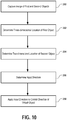
- Figure 10 illustrates a method for providing directional input to a video game, in accordance with an embodiment of the invention.
- the method initiates at operation 250 with capturing an image of a first object and a second object, the first object and the second object being defined at a fixed distance from each other.
- three-dimensional location of the first object is determined based on analysis of the captured image
- a two-dimensional location of the second object is determined based on analysis of the captured image.
- an input direction for a video game is determined based on the three-dimensional location of the first object and the two-dimensional location of the second object.
- the input direction is applied to control the direction of a virtual object within the video game.
- the presently described embodiments demonstrate how directional input can be determined from tracked locations of tracking objects.
- an existing controller device having a single tracking object can be enhanced via coupling of a second tracking object, such as an LED.
- This coupling enables significantly improved directional determination in accordance with techniques described herein. While specific embodiments have been provided to demonstrate various ways of coupling two tracking objects to facilitate directional input determination, these are described by way of example and not by way of limitation. Those skilled in the art having read the present disclosure will realize additional embodiments falling within the scope of the present invention.
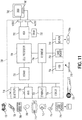
- Figure 11 illustrates hardware and user interfaces that may be used to provide interactivity with a video game, in accordance with one embodiment of the present invention.
- Figure 11 schematically illustrates the overall system architecture of the Sony® Playstation 3® entertainment device, a console that may be compatible for interfacing a control device with a computer program executing at a base computing device in accordance with embodiments of the present invention.
- a system unit 700 is provided, with various peripheral devices connectable to the system unit 700.
- the system unit 700 comprises: a Cell processor 728; a Rambus® dynamic random access memory (XDRAM) unit 726; a Reality Synthesizer graphics unit 730 with a dedicated video random access memory (VRAM) unit 732; and an I/O bridge 734.
- XDRAM Rambus® dynamic random access memory
- VRAM dedicated video random access memory
- the system unit 700 also comprises a Blu Ray® Disk BD-ROM® optical disk reader 740 for reading from a disk 740a and a removable slot-in hard disk drive (HDD) 736, accessible through the I/O bridge 734.
- the system unit 700 also comprises a memory card reader 738 for reading compact flash memory cards, Memory Stick® memory cards and the like, which is similarly accessible through the I/O bridge 734.
- the I/O bridge 734 also connects to six Universal Serial Bus (USB) 2.0 ports 724; a gigabit Ethernet port 722; an IEEE 802.1 lb/g wireless network (Wi-Fi) port 720; and a Bluetooth® wireless link port 718 capable of supporting up to seven Bluetooth connections.
- USB Universal Serial Bus
- Wi-Fi IEEE 802.1 lb/g wireless network
- Bluetooth® wireless link port 718 capable of supporting up to seven Bluetooth connections.
- the I/O bridge 734 handles all wireless, USB and Ethernet data, including data from one or more game controllers 702-703. For example when a user is playing a game, the I/O bridge 734 receives data from the game controller 702-703 via a Bluetooth link and directs it to the Cell processor 728, which updates the current state of the game accordingly.
- the wireless, USB and Ethernet ports also provide connectivity for other peripheral devices in addition to game controllers 702-703, such as: a remote control 704; a keyboard 706; a mouse 708; a portable entertainment device 710 such as a Sony Playstation Portable® entertainment device; a video camera such as an EyeToy® video camera 712; a microphone headset 714; and a microphone 715.
- peripheral devices may therefore in principle be connected to the system unit 700 wirelessly; for example the portable entertainment device 710 may communicate via a Wi-Fi ad-hoc connection, whilst the microphone headset 714 may communicate via a Bluetooth link.
- Playstation 3 device is also potentially compatible with other peripheral devices such as digital video recorders (DVRs), set-top boxes, digital cameras, portable media players, Voice over IP telephones, mobile telephones, printers and scanners.
- DVRs digital video recorders
- set-top boxes digital cameras
- portable media players Portable media players
- Voice over IP telephones mobile telephones, printers and scanners.
- a legacy memory card reader 716 may be connected to the system unit via a USB port 724, enabling the reading of memory cards 748 of the kind used by the Playstation® or Playstation 2® devices.
- the game controllers 702-703 are operable to communicate wirelessly with the system unit 700 via the Bluetooth link, or to be connected to a USB port, thereby also providing power by which to charge the battery of the game controllers 702-703.
- Game controllers 702-703 can also include memory, a processor, a memory card reader, permanent memory such as flash memory, light emitters such as an illuminated spherical section, LEDs, or infrared lights, microphone and speaker for ultrasound communications, an acoustic chamber, a digital camera, an internal clock, a recognizable shape such as the spherical section facing the game console, and wireless communications using protocols such as Bluetooth®, WiFiTM, etc.
- Game controller 702 is a controller designed to be used with two hands, and game controller 703 is a single-hand controller with an attachment.
- the game controller is susceptible to three-dimensional location determination. Consequently gestures and movements by the user of the game controller may be translated as inputs to a game in addition to or instead of conventional button or joystick commands.
- other wirelessly enabled peripheral devices such as the PlaystationTM Portable device may be used as a controller.
- additional game or control information (for example, control instructions or number of lives) may be provided on the screen of the device.
- control devices such as a dance mat (not shown), a light gun (not shown), a steering wheel and pedals (not shown) or bespoke controllers, such as a single or several large buttons for a rapid-response quiz game (also not shown).
- the remote control 704 is also operable to communicate wirelessly with the system unit 700 via a Bluetooth link.
- the remote control 704 comprises controls suitable for the operation of the Blu RayTM Disk BD-ROM reader 540 and for the navigation of disk content.
- the Blu RayTM Disk BD-ROM reader 740 is operable to read CD-ROMs compatible with the Playstation and PlayStation 2 devices, in addition to conventional pre-recorded and recordable CDs, and so-called Super Audio CDs.
- the reader 740 is also operable to read DVD-ROMs compatible with the Playstation 2 and PlayStation 3 devices, in addition to conventional pre-recorded and recordable DVDs.
- the reader 740 is further operable to read BD-ROMs compatible with the Playstation 3 device, as well as conventional pre-recorded and recordable Blu-Ray Disks.
- the system unit 700 is operable to supply audio and video, either generated or decoded by the Playstation 3 device via the Reality Synthesizer graphics unit 730, through audio and video connectors to a display and sound output device 742 such as a monitor or television set having a display 744 and one or more loudspeakers 746.
- the audio connectors 750 may include conventional analogue and digital outputs whilst the video connectors 752 may variously include component video, S-video, composite video and one or more High Definition Multimedia Interface (HDMI) outputs. Consequently, video output may be in formats such as PAL or NTSC, or in 720p, 1080i or 1080p high definition.
- Audio processing (generation, decoding and so on) is performed by the Cell processor 728.
- the Playstation 3 device's operating system supports Dolby® 5.1 surround sound, Dolby® Theatre Surround (DTS), and the decoding of 7.1 surround sound from Blu-Ray® disks.
- DTS Dolby® Theatre Surround
- the video camera 712 comprises a single charge coupled device (CCD), an LED indicator, and hardware-based real-time data compression and encoding apparatus so that compressed video data may be transmitted in an appropriate format such as an intra-image based MPEG (motion picture expert group) standard for decoding by the system unit 700.
- the camera LED indicator is arranged to illuminate in response to appropriate control data from the system unit 700, for example to signify adverse lighting conditions.
- Embodiments of the video camera 712 may variously connect to the system unit 700 via a USB, Bluetooth or Wi-Fi communication port.
- Embodiments of the video camera may include one or more associated microphones and also be capable of transmitting audio data.
- the CCD may have a resolution suitable for high-definition video capture. In use, images captured by the video camera may for example be incorporated within a game or interpreted as game control inputs.
- the camera is an infrared camera suitable for detecting infrared light.
- an appropriate piece of software such as a device driver should be provided.
- Device driver technology is well-known and will not be described in detail here, except to say that the skilled man will be aware that a device driver or similar software interface may be required in the present embodiment described.
- FIG. 12 illustrates additional hardware that may be used to process instructions, in accordance with one embodiment of the present invention.
- Cell processor 728 has an architecture comprising four basic components: external input and output structures comprising a memory controller 860 and a dual bus interface controller 870A, B; a main processor referred to as the Power Processing Element 850; eight co-processors referred to as Synergistic Processing Elements (SPEs) 810A-H; and a circular data bus connecting the above components referred to as the Element Interconnect Bus 880.
- the total floating point performance of the Cell processor is 218 GFLOPS, compared with the 6.2 GFLOPs of the Playstation 2 device's Emotion Engine.
- the Power Processing Element (PPE) 850 is based upon a two-way simultaneous multithreading Power 570 compliant PowerPC core (PPU) 855 running with an internal clock of 3.2 GHz. It comprises a 512 kB level 2 (L2) cache and a 32 kB level 1 (L1) cache.
- the PPE 850 is capable of eight single position operations per clock cycle, translating to 25.6 GFLOPs at 3.2 GHz.
- the primary role of the PPE 850 is to act as a controller for the Synergistic Processing Elements 810A-H, which handle most of the computational workload. In operation the PPE 850 maintains a job queue, scheduling jobs for the Synergistic Processing Elements 810A-H and monitoring their progress. Consequently each Synergistic Processing Element 810A-H runs a kernel whose role is to fetch a job, execute it and synchronized with the PPE 850.
- Each Synergistic Processing Element (SPE) 810A-H comprises a respective Synergistic Processing Unit (SPU) 820A-H, and a respective Memory Flow Controller (MFC) 840A-H comprising in turn a respective Dynamic Memory Access Controller (DMAC) 842A-H, a respective Memory Management Unit (MMU) 844A-H and a bus interface (not shown).
- SPU 820A-H is a RISC processor clocked at 3.2 GHz and comprising 256 kB local RAM 830A-H, expandable in principle to 4 GB.
- Each SPE gives a theoretical 25.6 GFLOPS of single precision performance.
- An SPU can operate on 4 single precision floating point members, 4 32-bit numbers, 8 16-bit integers, or 16 8-bit integers in a single clock cycle. In the same clock cycle it can also perform a memory operation.
- the SPU 820A-H does not directly access the system memory XDRAM 726; the 64-bit addresses formed by the SPU 820A-H are passed to the MFC 840A-H which instructs its DMA controller 842A-H to access memory via the Element Interconnect Bus 880 and the memory controller 860.
- the Element Interconnect Bus (EIB) 880 is a logically circular communication bus internal to the Cell processor 728 which connects the above processor elements, namely the PPE 850, the memory controller 860, the dual bus interface 870A,B and the 8 SPEs 810A-H, totaling 12 participants. Participants can simultaneously read and write to the bus at a rate of 8 bytes per clock cycle. As noted previously, each SPE 810A-H comprises a DMAC 842A-H for scheduling longer read or write sequences.
- the EIB comprises four channels, two each in clockwise and anticlockwise directions. Consequently for twelve participants, the longest step-wise dataflow between any two participants is six steps in the appropriate direction.
- the theoretical peak instantaneous EIB bandwidth for 12 slots is therefore 96B per clock, in the event of full utilization through arbitration between participants. This equates to a theoretical peak bandwidth of 307.2 GB/s (gigabytes per second) at a clock rate of 3.2GHz.
- the memory controller 860 comprises an XDRAM interface 862, developed by Rambus Incorporated.
- the memory controller interfaces with the Rambus XDRAM 726 with a theoretical peak bandwidth of 25.6 GB/s.
- the dual bus interface 870A,B comprises a Rambus FlexIO® system interface 872A,B.
- the interface is organized into 12 channels each being 8 bits wide, with five paths being inbound and seven outbound. This provides a theoretical peak bandwidth of 62.4 GB/s (36.4 GB/s outbound, 26 GB/s inbound) between the Cell processor and the I/O Bridge 734 via controller 870A and the Reality Simulator graphics unit 730 via controller 870B.
- Data sent by the Cell processor 728 to the Reality Simulator graphics unit 730 will typically comprise display lists, being a sequence of commands to draw vertices, apply textures to polygons, specify lighting conditions, and so on.
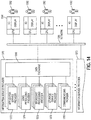
- FIG 13 is an exemplary illustration of scene A through scene E with respective user A through user E interacting with game clients 1102 that are connected to server processing via the internet, in accordance with one embodiment of the present invention.
- a game client is a device that allows users to connect to server applications and processing via the internet.
- the game client allows users to access and playback online entertainment content such as but not limited to games, movies, music and photos. Additionally, the game client can provide access to online communications applications such as VOIP, text chat protocols, and email.
- the controller is a game client specific controller while in other embodiments, the controller can be a keyboard and mouse combination.
- the game client is a standalone device capable of outputting audio and video signals to create a multimedia environment through a monitor/television and associated audio equipment.
- the game client can be, but is not limited to a thin client, an internal PCI-express card, an external PCI-express device, an ExpressCard device, an internal, external, or wireless USB device, or a Firewire device, etc.
- the game client is integrated with a television or other multimedia device such as a DVR, Blu-Ray player, DVD player or multichannel receiver.
- FIG. 13 illustrates a view from behind user C as he looks at a monitor displaying a game and buddy list from the game client 1102C.
- Figure 13 shows a single server processing module, in one embodiment, there are multiple server processing modules throughout the world. Each server processing module includes sub-modules for user session control, sharing/communication logic, user geo-location, and load balance processing service. Furthermore, a server processing module includes network processing and distributed storage.
- user session control may be used to authenticate the user.
- An authenticated user can have associated virtualized distributed storage and virtualized network processing. Examples items that can be stored as part of a user's virtualized distributed storage include purchased media such as, but not limited to games, videos and music etc. Additionally, distributed storage can be used to save game status for multiple games, customized settings for individual games, and general settings for the game client.
- the user geo-location module of the server processing is used to determine the geographic location of a user and their respective game client. The user's geographic location can be used by both the sharing/communication logic and the load balance processing service to optimize performance based on geographic location and processing demands of multiple server processing modules.
- Virtualizing either or both network processing and network storage would allow processing tasks from game clients to be dynamically shifted to underutilized server processing module(s).
- load balancing can be used to minimize latency associated with both recall from storage and with data transmission between server processing modules and game clients.
- the server processing module has instances of server application A and server application B.
- the server processing module is able to support multiple server applications as indicated by server application X 1 and server application X 2 .
- server processing is based on cluster computing architecture that allows multiple processors within a cluster to process server applications.
- a different type of multi-computer processing scheme is applied to process the server applications. This allows the server processing to be scaled in order to accommodate a larger number of game clients executing multiple client applications and corresponding server applications. Alternatively, server processing can be scaled to accommodate increased computing demands necessitated by more demanding graphics processing or game, video compression, or application complexity.
- the server processing module performs the majority of the processing via the server application. This allows relatively expensive components such as graphics processors, RAM, and general processors to be centrally located and reduces to the cost of the game client. Processed server application data is sent back to the corresponding game client via the internet to be displayed on a monitor.
- Scene C illustrates an exemplary application that can be executed by the game client and server processing module.
- game client 1102C allows user C to create and view a buddy list 1120 that includes user A, user B, user D and user E.
- user C is able to see either real time images or avatars of the respective user on monitor 1104C.
- Server processing executes the respective applications of game client 1102C and with the respective game clients 1102 of users A, user B, user D and user E. Because the server processing is aware of the applications being executed by game client B, the buddy list for user A can indicate which game user B is playing. Further still, in one embodiment, user A can view actual in game video directly from user B. This is enabled by merely sending processed server application data for user B to game client A in addition to game client B.
- the communication application can allow real-time communications between buddies. As applied to the previous example, this allows user A to provide encouragement or hints while watching real-time video of user B.
- two-way real time voice communication is established through a client/server application.
- a client/server application enables text chat.
- a client/server application converts speech to text for display on a buddy's screen.
- Scene D and scene E illustrate respective user D and user E interacting with game consoles 1110D and 1110E respectively.
- Each game console 1110D and 1110E are connected to the server processing module and illustrate a network where the server processing modules coordinates game play for both game consoles and game clients.
- FIG 14 illustrates an embodiment of an Information Service Provider architecture.
- Information Service Providers (ISP) 1370 delivers a multitude of information services to users 1382 geographically dispersed and connected via network 1386.
- An ISP can deliver just one type of service, such as stock price updates, or a variety of services such as broadcast media, news, sports, gaming, etc.
- the services offered by each ISP are dynamic, that is, services can be added or taken away at any point in time.
- the ISP providing a particular type of service to a particular individual can change over time. For example, a user may be served by an ISP in near proximity to the user while the user is in her home town, and the user may be served by a different ISP when the user travels to a different city.
- the home-town ISP will transfer the required information and data to the new ISP, such that the user information "follows" the user to the new city making the data closer to the user and easier to access.
- a master-server relationship may be established between a master ISP, which manages the information for the user, and a server ISP that interfaces directly with the user under control from the master ISP.
- the data is transferred from one ISP to another ISP as the client moves around the world to make the ISP in better position to service the user be the one that delivers these services.
- ISP 1370 includes Application Service Provider (ASP) 1372, which provides computer-based services to customers over a network.
- ASP Application Service Provider
- Software offered using an ASP model is also sometimes called on-demand software or software as a service (SaaS).
- SaaS software as a service
- a simple form of providing access to a particular application program (such as customer relationship management) is by using a standard protocol such as HTTP.
- the application software resides on the vendor's system and is accessed by users through a web browser using HTML, by special purpose client software provided by the vendor, or other remote interface such as a thin client.
- Cloud computing is a style of computing in which dynamically scalable and often virtualized resources are provided as a service over the Internet. Users do not need to be an expert in the technology infrastructure in the "cloud” that supports them. Cloud computing can be divided in different services, such as Infrastructure as a Service (IaaS), Platform as a Service (PaaS), and Software as a Service (SaaS). Cloud computing services often provide common business applications online that are accessed from a web browser, while the software and data are stored on the servers.
- IaaS Infrastructure as a Service
- PaaS Platform as a Service
- SaaS Software as a Service
- Cloud computing services often provide common business applications online that are accessed from a web browser, while the software and data are stored on the servers.
- the term cloud is used as a metaphor for the Internet, based on how the Internet is depicted in computer network diagrams and is an abstraction for the complex infrastructure it conceals.
- ISP 1370 includes a Game Processing Server (GPS) 1374 which is used by game clients to play single and multiplayer video games.
- GPS Game Processing Server
- Most video games played over the Internet operate via a connection to a game server.
- games use a dedicated server application that collects data from players and distributes it to other players. This is more efficient and effective than a peer-to-peer arrangement, but it requires a separate server to host the server application.
- the GPS establishes communication between the players and their respective game-playing devices exchange information without relying on the centralized GPS.
- Dedicated GPSs are servers which run independently of the client. Such servers are usually run on dedicated hardware located in data centers, providing more bandwidth and dedicated processing power. Dedicated servers are the preferred method of hosting game servers for most PC-based multiplayer games. Massively multiplayer online games run on dedicated servers usually hosted by the software company that owns the game title, allowing them to control and update content.
- Broadcast Processing Server (BPS) 1376 distributes audio or video signals to an audience. Broadcasting to a very narrow range of audience is sometimes called narrowcasting.
- the final leg of broadcast distribution is how the signal gets to the listener or viewer, and it may come over the air as with a radio station or TV station to an antenna and receiver, or may come through cable TV or cable radio (or "wireless cable”) via the station or directly from a network.
- the Internet may also bring either radio or TV to the recipient, especially with multicasting allowing the signal and bandwidth to be shared.
- broadcasts have been delimited by a geographic region, such as national broadcasts or regional broadcast. However, with the proliferation of fast internet, broadcasts are not defined by geographies as the content can reach almost any country in the world.
- SSP 1378 provides computer storage space and related management services. SSPs also offer periodic backup and archiving. By offering storage as a service, users can order more storage as required. Another major advantage is that SSPs include backup services and users will not lose all their data if their computers' hard drives fail. Further, a plurality of SSPs can have total or partial copies of the user data, allowing users to access data in an efficient way independently of where the user is located or the device being used to access the data. For example, a user can access personal files in the home computer, as well as in a mobile phone while the user is on the move.
- Communications Provider 380 provides connectivity to the users.
- One kind of Communications Provider is an Internet Service Provider (ISP) which offers access to the Internet.
- the ISP connects its customers using a data transmission technology appropriate for delivering Internet Protocol datagrams, such as dial-up, DSL, cable modem, wireless or dedicated high-speed interconnects.
- the Communications Provider can also provide messaging services, such as e-mail, instant messaging, and SMS texting.
- Another type of Communications Provider is the Network Service provider (NSP) which sells bandwidth or network access by providing direct backbone access to the Internet.
- Network service providers may consist of telecommunications companies, data carriers, wireless communications providers, Internet service providers, cable television operators offering high-speed Internet access, etc.
- Data Exchange 1388 interconnects the several modules inside ISP 1370 and connects these modules to users 1382 via network 1386.
- Data Exchange 1388 can cover a small area where all the modules of ISP 1370 are in close proximity, or can cover a large geographic area when the different modules are geographically dispersed.
- Data Exchange 1388 can include a fast Gigabit Ethernet (or faster) within a cabinet of a data center, or an intercontinental virtual area network (VLAN).
- VLAN virtual area network
- client device 1384 which includes at least a CPU, a display and I/O.
- the client device can be a PC, a mobile phone, a netbook, a PDA, etc.
- ISP 1370 recognizes the type of device used by the client and adjusts the communication method employed. In other cases, client devices use a standard communications method, such as html, to access ISP 1370.
- Embodiments of the present invention may be practiced with various computer system configurations including hand-held devices, microprocessor systems, microprocessor-based or programmable consumer electronics, minicomputers, mainframe computers and the like.
- the invention can also be practiced in distributed computing environments where tasks are performed by remote processing devices that are linked through a wire-based or wireless network.
- the invention can employ various computer-implemented operations involving data stored in computer systems. These operations are those requiring physical manipulation of physical quantities. Any of the operations described herein that form part of the invention are useful machine operations.
- the invention also relates to a device or an apparatus for performing these operations.
- the apparatus can be specially constructed for the required purpose, or the apparatus can be a general-purpose computer selectively activated or configured by a computer program stored in the computer.
- various general-purpose machines can be used with computer programs written in accordance with the teachings herein, or it may be more convenient to construct a more specialized apparatus to perform the required operations.
- the invention can also be embodied as computer readable code on a computer readable medium.
- the computer readable medium is any data storage device that can store data, which can be thereafter be read by a computer system. Examples of the computer readable medium include hard drives, network attached storage (NAS), read-only memory, random-access memory, CD-ROMs, CD-Rs, CD-RWs, magnetic tapes and other optical and non-optical data storage devices.
- the computer readable medium can include computer readable tangible medium distributed over a network-coupled computer system so that the computer readable code is stored and executed in a distributed fashion.
Landscapes
- Engineering & Computer Science (AREA)
- Multimedia (AREA)
- Human Computer Interaction (AREA)
- General Engineering & Computer Science (AREA)
- Theoretical Computer Science (AREA)
- Physics & Mathematics (AREA)
- General Physics & Mathematics (AREA)
- User Interface Of Digital Computer (AREA)
- Position Input By Displaying (AREA)
- Processing Or Creating Images (AREA)
- Image Analysis (AREA)
- Length Measuring Devices By Optical Means (AREA)
Claims (10)
- Procédé pour fournir une entrée directionnelle à un jeu vidéo, consistant :à capturer, au moyen d'un dispositif de capture d'image (14), des images d'un dispositif d'entrée (18), le dispositif d'entrée comprenant un boîtier ayant une longueur et un réceptacle défini au niveau d'une extrémité de la longueur du boîtier, le réceptacle étant configuré pour recevoir un dispositif de commande de mouvement ayant un premier objet, le dispositif d'entrée comprenant en outre un second objet (22) défini le long de la longueur du boîtier, dans lequel le premier objet et le second objet sont séparés l'un de l'autre par une distance fixe (D) et sont configurés pour être maintenus à des profondeurs sensiblement différentes par rapport au dispositif de capture d'image ;à traiter les images capturées ainsi que des données de capteur de mouvement supplémentaires provenant de capteurs de mouvement inclus dans le dispositif de commande de mouvement pour suivre une localisation tridimensionnelle du premier objet comprenant une profondeur du premier objet par rapport au dispositif de capture d'image ;à traiter les images capturées seules pour suivre seulement une localisation bidimensionnelle du second objet qui définit une position latérale du second objet par rapport au dispositif de capture d'image ; età déterminer une direction d'entrée en se basant sur la localisation tridimensionnelle suivie du premier objet, la localisation bidimensionnelle suivie du second objet et la distance fixe connue entre les premier et second objets.
- Procédé selon la revendication 1, dans lequel la direction d'entrée est vers un dispositif d'affichage.
- Procédé selon la revendication 1, dans lequel la direction d'entrée définit une direction d'un objet virtuel dans le jeu vidéo.
- Procédé selon la revendication 3, dans lequel l'objet virtuel est une arme.
- Procédé selon la revendication 1, consistant en outre :
à éclairer le premier objet et le second objet. - Système pour fournir une entrée directionnelle à un jeu vidéo, comprenant :un dispositif de capture d'image (14) configuré pour capturer des images d'un dispositif d'entrée (18), le dispositif d'entrée comprenant un boîtier ayant une longueur et un réceptacle défini au niveau d'une extrémité de la longueur du boîtier, le réceptacle étant configuré pour recevoir un dispositif de commande de mouvement ayant un premier objet, le dispositif d'entrée comprenant en outre un second objet (22) défini le long de la longueur du boîtier, dans lequel le premier objet et le second objet sont séparés l'un de l'autre par une distance fixe (D) et sont configurés pour être maintenus à des profondeurs sensiblement différentes par rapport au dispositif de capture d'image ;des moyens de traitement conçus pour traiter les images capturées ainsi que des données de capteur de mouvement supplémentaires provenant de capteurs de mouvement inclus dans le dispositif de commande de mouvement pour suivre une localisation tridimensionnelle du premier objet comprenant une profondeur du premier objet par rapport au dispositif de capture d'image, et conçus pour traiter les images capturées seules pour suivre seulement une localisation bidimensionnelle du second objet qui définit une position latérale du second objet par rapport au dispositif de capture d'image ; etdes moyens de détermination conçus pour déterminer une direction d'entrée en se basant sur la localisation tridimensionnelle suivie du premier objet, la localisation bidimensionnelle suivie du second objet et la distance fixe connue entre les premier et second objets.
- Système selon la revendication 6, dans lequel la direction d'entrée est vers un dispositif d'affichage.
- Système selon la revendication 6, dans lequel la direction d'entrée définit une direction d'un objet virtuel dans le jeu vidéo.
- Système selon la revendication 8, dans lequel l'objet virtuel est une arme.
- Système selon la revendication 6, dans lequel le premier objet et le second objet sont éclairés.
Applications Claiming Priority (2)
| Application Number | Priority Date | Filing Date | Title |
|---|---|---|---|
| US13/333,786 US8888593B2 (en) | 2005-10-26 | 2011-12-21 | Directional input for a video game |
| PCT/US2012/071386 WO2013096844A2 (fr) | 2011-12-21 | 2012-12-21 | Entrée directionnelle pour un jeu vidéo |
Publications (2)
| Publication Number | Publication Date |
|---|---|
| EP2794039A2 EP2794039A2 (fr) | 2014-10-29 |
| EP2794039B1 true EP2794039B1 (fr) | 2019-06-19 |
Family
ID=47553462
Family Applications (1)
| Application Number | Title | Priority Date | Filing Date |
|---|---|---|---|
| EP12813704.9A Active EP2794039B1 (fr) | 2011-12-21 | 2012-12-21 | Entrée directionnelle pour un jeu vidéo |
Country Status (5)
| Country | Link |
|---|---|
| US (1) | US8888593B2 (fr) |
| EP (1) | EP2794039B1 (fr) |
| JP (1) | JP6158220B2 (fr) |
| CN (2) | CN104010706B (fr) |
| WO (1) | WO2013096844A2 (fr) |
Families Citing this family (19)
| Publication number | Priority date | Publication date | Assignee | Title |
|---|---|---|---|---|
| US8904430B2 (en) | 2008-04-24 | 2014-12-02 | Sony Computer Entertainment America, LLC | Method and apparatus for real-time viewer interaction with a media presentation |
| JP5829040B2 (ja) * | 2011-04-11 | 2015-12-09 | 任天堂株式会社 | ゲームシステム、ゲーム装置、ゲームプログラム、および画像生成方法 |
| US20130104083A1 (en) * | 2011-10-21 | 2013-04-25 | Digital Artforms, Inc. | Systems and methods for human-computer interaction using a two handed interface |
| US8976249B2 (en) * | 2011-11-04 | 2015-03-10 | Empire Technology Development Llc | IR signal capture for images |
| US9216133B2 (en) * | 2013-01-16 | 2015-12-22 | Elwha Llc | Using a 3D display to train a weak eye |
| EP2987026B1 (fr) | 2013-04-05 | 2020-03-25 | Andra Motion Technologies Inc. | Système et procédé permettant de contrôler un équipement lié à la capture d'image |
| US20140364180A1 (en) * | 2013-06-10 | 2014-12-11 | Edward Olivar | Predator 80 systems |
| JP6301707B2 (ja) * | 2014-04-03 | 2018-03-28 | 株式会社カプコン | ゲームプログラム及びゲームシステム |
| AU2015244158A1 (en) * | 2014-04-08 | 2016-09-15 | Eon Reality, Inc. | Interactive virtual reality systems and methods |
| CN105288998B (zh) * | 2015-09-23 | 2019-01-08 | 腾讯科技(深圳)有限公司 | 智能硬件的交互方法及装置 |
| CN105148513B (zh) | 2015-09-23 | 2017-06-06 | 腾讯科技(深圳)有限公司 | 智能硬件的操作方法及装置 |
| US20170354864A1 (en) * | 2016-06-11 | 2017-12-14 | Sony Interactive Entertainment Inc. | Directional Interface Object |
| CN107152887A (zh) * | 2017-05-14 | 2017-09-12 | 深圳游视虚拟现实技术有限公司 | 一种基于虚拟现实技术的模拟火箭筒操作训练方法和系统 |
| US10328339B2 (en) * | 2017-07-11 | 2019-06-25 | Specular Theory, Inc. | Input controller and corresponding game mechanics for virtual reality systems |
| US10155166B1 (en) | 2017-09-08 | 2018-12-18 | Sony Interactive Entertainment Inc. | Spatially and user aware second screen projection from a companion robot or device |
| JP6755843B2 (ja) | 2017-09-14 | 2020-09-16 | 株式会社東芝 | 音響処理装置、音声認識装置、音響処理方法、音声認識方法、音響処理プログラム及び音声認識プログラム |
| US10675536B2 (en) | 2018-10-03 | 2020-06-09 | Song Chen | Gaming system that alters target images produced by an LED array |
| US10744406B2 (en) * | 2018-10-19 | 2020-08-18 | North Carolina State University | Temporal axial alignment adapter for VR hand controllers |
| CN111773656A (zh) * | 2020-07-09 | 2020-10-16 | 网易(杭州)网络有限公司 | 虚拟对象选择控制方法、装置、手持终端及存储介质 |
Citations (3)
| Publication number | Priority date | Publication date | Assignee | Title |
|---|---|---|---|---|
| US20040046736A1 (en) * | 1997-08-22 | 2004-03-11 | Pryor Timothy R. | Novel man machine interfaces and applications |
| US20080015017A1 (en) * | 2006-05-09 | 2008-01-17 | Nintendo Co., Ltd. | Game controller |
| US20080261693A1 (en) * | 2008-05-30 | 2008-10-23 | Sony Computer Entertainment America Inc. | Determination of controller three-dimensional location using image analysis and ultrasonic communication |
Family Cites Families (11)
| Publication number | Priority date | Publication date | Assignee | Title |
|---|---|---|---|---|
| JP2000259340A (ja) * | 1999-03-12 | 2000-09-22 | Sony Corp | 入力装置および方法、入力システム、並びに提供媒体 |
| US7883415B2 (en) * | 2003-09-15 | 2011-02-08 | Sony Computer Entertainment Inc. | Method and apparatus for adjusting a view of a scene being displayed according to tracked head motion |
| US7646372B2 (en) * | 2003-09-15 | 2010-01-12 | Sony Computer Entertainment Inc. | Methods and systems for enabling direction detection when interfacing with a computer program |
| US10279254B2 (en) * | 2005-10-26 | 2019-05-07 | Sony Interactive Entertainment Inc. | Controller having visually trackable object for interfacing with a gaming system |
| EP2293172A3 (fr) * | 2005-10-26 | 2011-04-13 | Sony Computer Entertainment Inc. | Système et méthode d'interfaçage et programme informatique |
| EP2013865A4 (fr) * | 2006-05-04 | 2010-11-03 | Sony Comp Entertainment Us | Procedes et appareil pour appliquer des effets d'adaptation a une entree sur la base d'une ou plusiers donnees visuelles, acoustique, inertielles et melangees |
| US8696458B2 (en) | 2008-02-15 | 2014-04-15 | Thales Visionix, Inc. | Motion tracking system and method using camera and non-camera sensors |
| JP5429444B2 (ja) * | 2008-03-17 | 2014-02-26 | 株式会社セガ | ゲーム制御プログラムおよびゲーム装置 |
| JP5411473B2 (ja) * | 2008-09-16 | 2014-02-12 | 株式会社バンダイナムコゲームス | プログラム及びゲーム装置 |
| FR2957266B1 (fr) * | 2010-03-11 | 2012-04-20 | Parrot | Procede et appareil de telecommande d'un drone, notamment d'un drone a voilure tournante. |
| JP2011206483A (ja) * | 2010-03-30 | 2011-10-20 | Namco Bandai Games Inc | プログラム、情報記憶媒体、ゲーム装置及びゲームサーバ装置 |
-
2011
- 2011-12-21 US US13/333,786 patent/US8888593B2/en active Active
-
2012
- 2012-12-21 CN CN201280063556.4A patent/CN104010706B/zh active Active
- 2012-12-21 WO PCT/US2012/071386 patent/WO2013096844A2/fr active Application Filing
- 2012-12-21 EP EP12813704.9A patent/EP2794039B1/fr active Active
- 2012-12-21 JP JP2014548966A patent/JP6158220B2/ja active Active
- 2012-12-21 CN CN201710481428.6A patent/CN107362532B/zh active Active
Patent Citations (3)
| Publication number | Priority date | Publication date | Assignee | Title |
|---|---|---|---|---|
| US20040046736A1 (en) * | 1997-08-22 | 2004-03-11 | Pryor Timothy R. | Novel man machine interfaces and applications |
| US20080015017A1 (en) * | 2006-05-09 | 2008-01-17 | Nintendo Co., Ltd. | Game controller |
| US20080261693A1 (en) * | 2008-05-30 | 2008-10-23 | Sony Computer Entertainment America Inc. | Determination of controller three-dimensional location using image analysis and ultrasonic communication |
Also Published As
| Publication number | Publication date |
|---|---|
| CN107362532B (zh) | 2021-02-02 |
| CN104010706A (zh) | 2014-08-27 |
| JP2015506739A (ja) | 2015-03-05 |
| WO2013096844A3 (fr) | 2013-08-22 |
| US20120190448A1 (en) | 2012-07-26 |
| WO2013096844A2 (fr) | 2013-06-27 |
| JP6158220B2 (ja) | 2017-07-05 |
| EP2794039A2 (fr) | 2014-10-29 |
| CN107362532A (zh) | 2017-11-21 |
| CN104010706B (zh) | 2017-07-18 |
| US8888593B2 (en) | 2014-11-18 |
Similar Documents
| Publication | Publication Date | Title |
|---|---|---|
| EP2794039B1 (fr) | Entrée directionnelle pour un jeu vidéo | |
| US11065532B2 (en) | Split-screen presentation based on user location and controller location | |
| US8870654B2 (en) | Gaming controller | |
| US10610778B2 (en) | Gaming controller | |
| EP2470277B1 (fr) | Interaction avec un dispositif portable par l'intermédiaire d'un contrôleur sensible au mouvement | |
| US8882597B2 (en) | Hybrid separable motion controller | |
| US9990029B2 (en) | Interface object and motion controller for augmented reality | |
| US11771981B2 (en) | Sharing buffered gameplay in response to an input request |
Legal Events
| Date | Code | Title | Description |
|---|---|---|---|
| PUAI | Public reference made under article 153(3) epc to a published international application that has entered the european phase |
Free format text: ORIGINAL CODE: 0009012 |
|
| 17P | Request for examination filed |
Effective date: 20140705 |
|
| AK | Designated contracting states |
Kind code of ref document: A2 Designated state(s): AL AT BE BG CH CY CZ DE DK EE ES FI FR GB GR HR HU IE IS IT LI LT LU LV MC MK MT NL NO PL PT RO RS SE SI SK SM TR |
|
| DAX | Request for extension of the european patent (deleted) | ||
| RAP1 | Party data changed (applicant data changed or rights of an application transferred) |
Owner name: SONY INTERACTIVE ENTERTAINMENT INC. |
|
| PUAG | Search results despatched under rule 164(2) epc together with communication from examining division |
Free format text: ORIGINAL CODE: 0009017 |
|
| 17Q | First examination report despatched |
Effective date: 20160720 |
|
| B565 | Issuance of search results under rule 164(2) epc |
Effective date: 20160720 |
|
| RAP1 | Party data changed (applicant data changed or rights of an application transferred) |
Owner name: SONY INTERACTIVE ENTERTAINMENT INC. |
|
| STAA | Information on the status of an ep patent application or granted ep patent |
Free format text: STATUS: EXAMINATION IS IN PROGRESS |
|
| REG | Reference to a national code |
Ref country code: DE Ref legal event code: R079 Ref document number: 602012061229 Country of ref document: DE Free format text: PREVIOUS MAIN CLASS: A63F0013040000 Ipc: A63F0013428000 |
|
| RIC1 | Information provided on ipc code assigned before grant |
Ipc: A63F 13/26 20140101ALI20181121BHEP Ipc: A63F 13/245 20140101ALI20181121BHEP Ipc: G06F 3/0346 20130101ALI20181121BHEP Ipc: A63F 13/98 20140101ALI20181121BHEP Ipc: A63F 13/211 20140101ALI20181121BHEP Ipc: A63F 13/213 20140101ALI20181121BHEP Ipc: A63F 13/837 20140101ALI20181121BHEP Ipc: G06F 3/01 20060101ALI20181121BHEP Ipc: G06F 3/03 20060101ALI20181121BHEP Ipc: A63F 13/428 20140101AFI20181121BHEP |
|
| GRAP | Despatch of communication of intention to grant a patent |
Free format text: ORIGINAL CODE: EPIDOSNIGR1 |
|
| STAA | Information on the status of an ep patent application or granted ep patent |
Free format text: STATUS: GRANT OF PATENT IS INTENDED |
|
| INTG | Intention to grant announced |
Effective date: 20190107 |
|
| GRAS | Grant fee paid |
Free format text: ORIGINAL CODE: EPIDOSNIGR3 |
|
| GRAA | (expected) grant |
Free format text: ORIGINAL CODE: 0009210 |
|
| STAA | Information on the status of an ep patent application or granted ep patent |
Free format text: STATUS: THE PATENT HAS BEEN GRANTED |
|
| AK | Designated contracting states |
Kind code of ref document: B1 Designated state(s): AL AT BE BG CH CY CZ DE DK EE ES FI FR GB GR HR HU IE IS IT LI LT LU LV MC MK MT NL NO PL PT RO RS SE SI SK SM TR |
|
| REG | Reference to a national code |
Ref country code: GB Ref legal event code: FG4D |
|
| REG | Reference to a national code |
Ref country code: CH Ref legal event code: EP |
|
| REG | Reference to a national code |
Ref country code: IE Ref legal event code: FG4D |
|
| REG | Reference to a national code |
Ref country code: DE Ref legal event code: R096 Ref document number: 602012061229 Country of ref document: DE |
|
| REG | Reference to a national code |
Ref country code: AT Ref legal event code: REF Ref document number: 1144751 Country of ref document: AT Kind code of ref document: T Effective date: 20190715 |
|
| REG | Reference to a national code |
Ref country code: NL Ref legal event code: MP Effective date: 20190619 |
|
| PG25 | Lapsed in a contracting state [announced via postgrant information from national office to epo] |
Ref country code: LT Free format text: LAPSE BECAUSE OF FAILURE TO SUBMIT A TRANSLATION OF THE DESCRIPTION OR TO PAY THE FEE WITHIN THE PRESCRIBED TIME-LIMIT Effective date: 20190619 Ref country code: HR Free format text: LAPSE BECAUSE OF FAILURE TO SUBMIT A TRANSLATION OF THE DESCRIPTION OR TO PAY THE FEE WITHIN THE PRESCRIBED TIME-LIMIT Effective date: 20190619 Ref country code: SE Free format text: LAPSE BECAUSE OF FAILURE TO SUBMIT A TRANSLATION OF THE DESCRIPTION OR TO PAY THE FEE WITHIN THE PRESCRIBED TIME-LIMIT Effective date: 20190619 Ref country code: NO Free format text: LAPSE BECAUSE OF FAILURE TO SUBMIT A TRANSLATION OF THE DESCRIPTION OR TO PAY THE FEE WITHIN THE PRESCRIBED TIME-LIMIT Effective date: 20190919 Ref country code: AL Free format text: LAPSE BECAUSE OF FAILURE TO SUBMIT A TRANSLATION OF THE DESCRIPTION OR TO PAY THE FEE WITHIN THE PRESCRIBED TIME-LIMIT Effective date: 20190619 Ref country code: FI Free format text: LAPSE BECAUSE OF FAILURE TO SUBMIT A TRANSLATION OF THE DESCRIPTION OR TO PAY THE FEE WITHIN THE PRESCRIBED TIME-LIMIT Effective date: 20190619 |
|
| REG | Reference to a national code |
Ref country code: LT Ref legal event code: MG4D |
|
| PG25 | Lapsed in a contracting state [announced via postgrant information from national office to epo] |
Ref country code: BG Free format text: LAPSE BECAUSE OF FAILURE TO SUBMIT A TRANSLATION OF THE DESCRIPTION OR TO PAY THE FEE WITHIN THE PRESCRIBED TIME-LIMIT Effective date: 20190919 Ref country code: GR Free format text: LAPSE BECAUSE OF FAILURE TO SUBMIT A TRANSLATION OF THE DESCRIPTION OR TO PAY THE FEE WITHIN THE PRESCRIBED TIME-LIMIT Effective date: 20190920 Ref country code: LV Free format text: LAPSE BECAUSE OF FAILURE TO SUBMIT A TRANSLATION OF THE DESCRIPTION OR TO PAY THE FEE WITHIN THE PRESCRIBED TIME-LIMIT Effective date: 20190619 Ref country code: RS Free format text: LAPSE BECAUSE OF FAILURE TO SUBMIT A TRANSLATION OF THE DESCRIPTION OR TO PAY THE FEE WITHIN THE PRESCRIBED TIME-LIMIT Effective date: 20190619 |
|
| REG | Reference to a national code |
Ref country code: AT Ref legal event code: MK05 Ref document number: 1144751 Country of ref document: AT Kind code of ref document: T Effective date: 20190619 |
|
| PG25 | Lapsed in a contracting state [announced via postgrant information from national office to epo] |
Ref country code: EE Free format text: LAPSE BECAUSE OF FAILURE TO SUBMIT A TRANSLATION OF THE DESCRIPTION OR TO PAY THE FEE WITHIN THE PRESCRIBED TIME-LIMIT Effective date: 20190619 Ref country code: NL Free format text: LAPSE BECAUSE OF FAILURE TO SUBMIT A TRANSLATION OF THE DESCRIPTION OR TO PAY THE FEE WITHIN THE PRESCRIBED TIME-LIMIT Effective date: 20190619 Ref country code: SK Free format text: LAPSE BECAUSE OF FAILURE TO SUBMIT A TRANSLATION OF THE DESCRIPTION OR TO PAY THE FEE WITHIN THE PRESCRIBED TIME-LIMIT Effective date: 20190619 Ref country code: AT Free format text: LAPSE BECAUSE OF FAILURE TO SUBMIT A TRANSLATION OF THE DESCRIPTION OR TO PAY THE FEE WITHIN THE PRESCRIBED TIME-LIMIT Effective date: 20190619 Ref country code: PT Free format text: LAPSE BECAUSE OF FAILURE TO SUBMIT A TRANSLATION OF THE DESCRIPTION OR TO PAY THE FEE WITHIN THE PRESCRIBED TIME-LIMIT Effective date: 20191021 Ref country code: CZ Free format text: LAPSE BECAUSE OF FAILURE TO SUBMIT A TRANSLATION OF THE DESCRIPTION OR TO PAY THE FEE WITHIN THE PRESCRIBED TIME-LIMIT Effective date: 20190619 Ref country code: RO Free format text: LAPSE BECAUSE OF FAILURE TO SUBMIT A TRANSLATION OF THE DESCRIPTION OR TO PAY THE FEE WITHIN THE PRESCRIBED TIME-LIMIT Effective date: 20190619 |
|
| PG25 | Lapsed in a contracting state [announced via postgrant information from national office to epo] |
Ref country code: IS Free format text: LAPSE BECAUSE OF FAILURE TO SUBMIT A TRANSLATION OF THE DESCRIPTION OR TO PAY THE FEE WITHIN THE PRESCRIBED TIME-LIMIT Effective date: 20191019 Ref country code: SM Free format text: LAPSE BECAUSE OF FAILURE TO SUBMIT A TRANSLATION OF THE DESCRIPTION OR TO PAY THE FEE WITHIN THE PRESCRIBED TIME-LIMIT Effective date: 20190619 Ref country code: IT Free format text: LAPSE BECAUSE OF FAILURE TO SUBMIT A TRANSLATION OF THE DESCRIPTION OR TO PAY THE FEE WITHIN THE PRESCRIBED TIME-LIMIT Effective date: 20190619 Ref country code: ES Free format text: LAPSE BECAUSE OF FAILURE TO SUBMIT A TRANSLATION OF THE DESCRIPTION OR TO PAY THE FEE WITHIN THE PRESCRIBED TIME-LIMIT Effective date: 20190619 |
|
| PG25 | Lapsed in a contracting state [announced via postgrant information from national office to epo] |
Ref country code: TR Free format text: LAPSE BECAUSE OF FAILURE TO SUBMIT A TRANSLATION OF THE DESCRIPTION OR TO PAY THE FEE WITHIN THE PRESCRIBED TIME-LIMIT Effective date: 20190619 |
|
| PG25 | Lapsed in a contracting state [announced via postgrant information from national office to epo] |
Ref country code: PL Free format text: LAPSE BECAUSE OF FAILURE TO SUBMIT A TRANSLATION OF THE DESCRIPTION OR TO PAY THE FEE WITHIN THE PRESCRIBED TIME-LIMIT Effective date: 20190619 Ref country code: DK Free format text: LAPSE BECAUSE OF FAILURE TO SUBMIT A TRANSLATION OF THE DESCRIPTION OR TO PAY THE FEE WITHIN THE PRESCRIBED TIME-LIMIT Effective date: 20190619 |
|
| PG25 | Lapsed in a contracting state [announced via postgrant information from national office to epo] |
Ref country code: IS Free format text: LAPSE BECAUSE OF FAILURE TO SUBMIT A TRANSLATION OF THE DESCRIPTION OR TO PAY THE FEE WITHIN THE PRESCRIBED TIME-LIMIT Effective date: 20200224 |
|
| REG | Reference to a national code |
Ref country code: DE Ref legal event code: R097 Ref document number: 602012061229 Country of ref document: DE |
|
| PLBE | No opposition filed within time limit |
Free format text: ORIGINAL CODE: 0009261 |
|
| STAA | Information on the status of an ep patent application or granted ep patent |
Free format text: STATUS: NO OPPOSITION FILED WITHIN TIME LIMIT |
|
| PG2D | Information on lapse in contracting state deleted |
Ref country code: IS |
|
| REG | Reference to a national code |
Ref country code: CH Ref legal event code: PL |
|
| 26N | No opposition filed |
Effective date: 20200603 |
|
| REG | Reference to a national code |
Ref country code: BE Ref legal event code: MM Effective date: 20191231 |
|
| PG25 | Lapsed in a contracting state [announced via postgrant information from national office to epo] |
Ref country code: SI Free format text: LAPSE BECAUSE OF FAILURE TO SUBMIT A TRANSLATION OF THE DESCRIPTION OR TO PAY THE FEE WITHIN THE PRESCRIBED TIME-LIMIT Effective date: 20190619 Ref country code: MC Free format text: LAPSE BECAUSE OF FAILURE TO SUBMIT A TRANSLATION OF THE DESCRIPTION OR TO PAY THE FEE WITHIN THE PRESCRIBED TIME-LIMIT Effective date: 20190619 |
|
| PG25 | Lapsed in a contracting state [announced via postgrant information from national office to epo] |
Ref country code: LU Free format text: LAPSE BECAUSE OF NON-PAYMENT OF DUE FEES Effective date: 20191221 Ref country code: IE Free format text: LAPSE BECAUSE OF NON-PAYMENT OF DUE FEES Effective date: 20191221 |
|
| PG25 | Lapsed in a contracting state [announced via postgrant information from national office to epo] |
Ref country code: CH Free format text: LAPSE BECAUSE OF NON-PAYMENT OF DUE FEES Effective date: 20191231 Ref country code: BE Free format text: LAPSE BECAUSE OF NON-PAYMENT OF DUE FEES Effective date: 20191231 Ref country code: LI Free format text: LAPSE BECAUSE OF NON-PAYMENT OF DUE FEES Effective date: 20191231 |
|
| PG25 | Lapsed in a contracting state [announced via postgrant information from national office to epo] |
Ref country code: CY Free format text: LAPSE BECAUSE OF FAILURE TO SUBMIT A TRANSLATION OF THE DESCRIPTION OR TO PAY THE FEE WITHIN THE PRESCRIBED TIME-LIMIT Effective date: 20190619 |
|
| PG25 | Lapsed in a contracting state [announced via postgrant information from national office to epo] |
Ref country code: HU Free format text: LAPSE BECAUSE OF FAILURE TO SUBMIT A TRANSLATION OF THE DESCRIPTION OR TO PAY THE FEE WITHIN THE PRESCRIBED TIME-LIMIT; INVALID AB INITIO Effective date: 20121221 Ref country code: MT Free format text: LAPSE BECAUSE OF FAILURE TO SUBMIT A TRANSLATION OF THE DESCRIPTION OR TO PAY THE FEE WITHIN THE PRESCRIBED TIME-LIMIT Effective date: 20190619 |
|
| PG25 | Lapsed in a contracting state [announced via postgrant information from national office to epo] |
Ref country code: MK Free format text: LAPSE BECAUSE OF FAILURE TO SUBMIT A TRANSLATION OF THE DESCRIPTION OR TO PAY THE FEE WITHIN THE PRESCRIBED TIME-LIMIT Effective date: 20190619 |
|
| P01 | Opt-out of the competence of the unified patent court (upc) registered |
Effective date: 20230519 |
|
| PGFP | Annual fee paid to national office [announced via postgrant information from national office to epo] |
Ref country code: GB Payment date: 20231227 Year of fee payment: 12 |
|
| PGFP | Annual fee paid to national office [announced via postgrant information from national office to epo] |
Ref country code: FR Payment date: 20231227 Year of fee payment: 12 |
|
| PGFP | Annual fee paid to national office [announced via postgrant information from national office to epo] |
Ref country code: DE Payment date: 20231229 Year of fee payment: 12 |