EP2793389A2 - Verschachtelte Motorsteuerungen für elektrisches Taxisystem - Google Patents
Verschachtelte Motorsteuerungen für elektrisches Taxisystem Download PDFInfo
- Publication number
- EP2793389A2 EP2793389A2 EP20140163206 EP14163206A EP2793389A2 EP 2793389 A2 EP2793389 A2 EP 2793389A2 EP 20140163206 EP20140163206 EP 20140163206 EP 14163206 A EP14163206 A EP 14163206A EP 2793389 A2 EP2793389 A2 EP 2793389A2
- Authority
- EP
- European Patent Office
- Prior art keywords
- motor controllers
- electric taxi
- taxi system
- pwm control
- motor
- Prior art date
- Legal status (The legal status is an assumption and is not a legal conclusion. Google has not performed a legal analysis and makes no representation as to the accuracy of the status listed.)
- Granted
Links
Images


Classifications
-
- B—PERFORMING OPERATIONS; TRANSPORTING
- B60—VEHICLES IN GENERAL
- B60L—PROPULSION OF ELECTRICALLY-PROPELLED VEHICLES; SUPPLYING ELECTRIC POWER FOR AUXILIARY EQUIPMENT OF ELECTRICALLY-PROPELLED VEHICLES; ELECTRODYNAMIC BRAKE SYSTEMS FOR VEHICLES IN GENERAL; MAGNETIC SUSPENSION OR LEVITATION FOR VEHICLES; MONITORING OPERATING VARIABLES OF ELECTRICALLY-PROPELLED VEHICLES; ELECTRIC SAFETY DEVICES FOR ELECTRICALLY-PROPELLED VEHICLES
- B60L50/00—Electric propulsion with power supplied within the vehicle
- B60L50/10—Electric propulsion with power supplied within the vehicle using propulsion power supplied by engine-driven generators, e.g. generators driven by combustion engines
- B60L50/13—Electric propulsion with power supplied within the vehicle using propulsion power supplied by engine-driven generators, e.g. generators driven by combustion engines using AC generators and AC motors
-
- H—ELECTRICITY
- H02—GENERATION; CONVERSION OR DISTRIBUTION OF ELECTRIC POWER
- H02P—CONTROL OR REGULATION OF ELECTRIC MOTORS, ELECTRIC GENERATORS OR DYNAMO-ELECTRIC CONVERTERS; CONTROLLING TRANSFORMERS, REACTORS OR CHOKE COILS
- H02P5/00—Arrangements specially adapted for regulating or controlling the speed or torque of two or more electric motors
- H02P5/74—Arrangements specially adapted for regulating or controlling the speed or torque of two or more electric motors controlling two or more AC dynamo-electric motors
-
- B—PERFORMING OPERATIONS; TRANSPORTING
- B60—VEHICLES IN GENERAL
- B60L—PROPULSION OF ELECTRICALLY-PROPELLED VEHICLES; SUPPLYING ELECTRIC POWER FOR AUXILIARY EQUIPMENT OF ELECTRICALLY-PROPELLED VEHICLES; ELECTRODYNAMIC BRAKE SYSTEMS FOR VEHICLES IN GENERAL; MAGNETIC SUSPENSION OR LEVITATION FOR VEHICLES; MONITORING OPERATING VARIABLES OF ELECTRICALLY-PROPELLED VEHICLES; ELECTRIC SAFETY DEVICES FOR ELECTRICALLY-PROPELLED VEHICLES
- B60L50/00—Electric propulsion with power supplied within the vehicle
- B60L50/10—Electric propulsion with power supplied within the vehicle using propulsion power supplied by engine-driven generators, e.g. generators driven by combustion engines
- B60L50/12—Electric propulsion with power supplied within the vehicle using propulsion power supplied by engine-driven generators, e.g. generators driven by combustion engines using AC generators and DC motors
-
- B—PERFORMING OPERATIONS; TRANSPORTING
- B64—AIRCRAFT; AVIATION; COSMONAUTICS
- B64C—AEROPLANES; HELICOPTERS
- B64C25/00—Alighting gear
- B64C25/32—Alighting gear characterised by elements which contact the ground or similar surface
- B64C25/405—Powered wheels, e.g. for taxing
-
- H—ELECTRICITY
- H02—GENERATION; CONVERSION OR DISTRIBUTION OF ELECTRIC POWER
- H02M—APPARATUS FOR CONVERSION BETWEEN AC AND AC, BETWEEN AC AND DC, OR BETWEEN DC AND DC, AND FOR USE WITH MAINS OR SIMILAR POWER SUPPLY SYSTEMS; CONVERSION OF DC OR AC INPUT POWER INTO SURGE OUTPUT POWER; CONTROL OR REGULATION THEREOF
- H02M5/00—Conversion of AC power input into AC power output, e.g. for change of voltage, for change of frequency, for change of number of phases
- H02M5/40—Conversion of AC power input into AC power output, e.g. for change of voltage, for change of frequency, for change of number of phases with intermediate conversion into DC
- H02M5/42—Conversion of AC power input into AC power output, e.g. for change of voltage, for change of frequency, for change of number of phases with intermediate conversion into DC by static converters
- H02M5/44—Conversion of AC power input into AC power output, e.g. for change of voltage, for change of frequency, for change of number of phases with intermediate conversion into DC by static converters using discharge tubes or semiconductor devices to convert the intermediate DC into AC
- H02M5/453—Conversion of AC power input into AC power output, e.g. for change of voltage, for change of frequency, for change of number of phases with intermediate conversion into DC by static converters using discharge tubes or semiconductor devices to convert the intermediate DC into AC using devices of a triode or transistor type requiring continuous application of a control signal
- H02M5/458—Conversion of AC power input into AC power output, e.g. for change of voltage, for change of frequency, for change of number of phases with intermediate conversion into DC by static converters using discharge tubes or semiconductor devices to convert the intermediate DC into AC using devices of a triode or transistor type requiring continuous application of a control signal using semiconductor devices only
-
- Y—GENERAL TAGGING OF NEW TECHNOLOGICAL DEVELOPMENTS; GENERAL TAGGING OF CROSS-SECTIONAL TECHNOLOGIES SPANNING OVER SEVERAL SECTIONS OF THE IPC; TECHNICAL SUBJECTS COVERED BY FORMER USPC CROSS-REFERENCE ART COLLECTIONS [XRACs] AND DIGESTS
- Y02—TECHNOLOGIES OR APPLICATIONS FOR MITIGATION OR ADAPTATION AGAINST CLIMATE CHANGE
- Y02T—CLIMATE CHANGE MITIGATION TECHNOLOGIES RELATED TO TRANSPORTATION
- Y02T50/00—Aeronautics or air transport
- Y02T50/80—Energy efficient operational measures, e.g. ground operations or mission management
Definitions
- the present disclosure relates to taxiing systems, and more specifically, to interleaved motor controllers for an electric taxiing system.
- Taxiing systems are used to control the movement of an aircraft on the ground under its own power.
- An airplane uses taxiways to taxi from one place on an airport to another; for example, when moving from a terminal to the runway.
- an electric taxi system includes a generator configured to provide an ac power source and a main controller configured to generate one or more PWM control signals.
- the electric taxi system also includes a plurality of motor controllers connected in parallel to the generator, wherein each of the plurality of motor controllers receives one of the one or more PWM control signals.
- the electric taxi system further includes a plurality of motors, wherein each of the plurality of motors are coupled to one of the plurality of motor controllers.
- an electric taxi system includes an AC power source and a main controller configured to generate PWM control signals.
- the electric taxi system also includes a plurality of motor controllers connected in parallel to the AC power source, wherein each of the plurality of motor controllers receives PWM control signals and wherein the control signals received by each of the motor controllers are time delayed from the control signals received by the other motor controllers.
- the electric taxi system further includes a plurality of motors, wherein each of the plurality of motors are coupled to one of the plurality of motor controllers.
- an electric taxi system includes a generator configured to provide an AC power source and a main controller configured to generate one or more control signals.
- the electric taxi system also includes a plurality of motor controllers connected in parallel to the generator, wherein each of the plurality of motor controllers receives PWM control signals and wherein each of the one or more control signals is time delayed from the other of the one or more control signals.
- the electric taxi system further includes a plurality of motors, wherein each of the plurality of motors are coupled to one of the plurality of motor controllers.
- the PWM control signals for each of the plurality of motor controllers will have identical waveforms, albeit time delayed for each motor controller, when each of the motors is providing equal torque and speed (i.e.
- the aircraft is taxiing and not turning).
- the PWM control signal waveforms for each motor controller will differ, however the center of the PWM pulses for each of the motor controllers will remain time delayed with respect to the center of the PWM pulses for the other motor controllers.
- the electric taxi system 100 includes a generator 102, a main controller 104, a plurality of motor controllers 106 and a plurality of motors 108.
- each of the plurality of motors 108 is an electric motor that is coupled to the aircraft landing gear 110 by a gearbox (not shown).
- the generator 102 is configured to supply AC power, at for example approximately 115 volts, to each of the plurality of motor controllers 106, which are each connected to the generator 102 in parallel.
- the multiple motor controllers 106 appear as parallel loads to the generator 102.
- Each of the plurality of motor controllers 106 is also configured to receive a control signal from the main controller 104.
- the main controller 104 may be a digital signal processing (DSP) circuit, a field-programmable gate array (FPGA), an application specific integrated circuit (ASIC) or the like.
- DSP digital signal processing
- FPGA field-programmable gate array
- ASIC application specific integrated circuit
- the PWM control signals provided by the main controller 104 are used by the motor controllers 106 to control the operation of the motors 108.
- the PWM control signals provided by the main controller 104 to the motor controllers 106 are rectangular pulse waveforms, which has a pulse width that is modulated to control the speed of the motor 108.
- the PWM control signals provided by the main controller 104 to the motor controllers 106 are interleaved, or delayed.
- the electric taxi system 100 includes four electric motors 108 that each has an associated motor controller 106.
- the main controller 104 may provide a PWM control signal to a first motor controller 106 in the form of a rectangular pulse waveform having a frequency of 10 kHz and a 100 microsecond period.
- the main controller 104 may provide a second PWM control signal to a second motor controller 106 in the form of a rectangular pulse waveform having a frequency of 10 kHz and a 100 microsecond period with the center of the second set of PWM pulses having a 25 microsecond delay relative to the first PWM control signal.
- the main controller 104 may provide a third PWM control signal to a third motor controller 106 in the form of a rectangular pulse waveform having a frequency of 10 kHz and a 100 microsecond period with the center of the third set of PWM pulses having a 50 microsecond delay relative to the first PWM control signal.
- the main controller 104 may provide a fourth set of PWM control signals to a fourth motor controller 106 in the form of a rectangular pulse waveforms having a frequency of 10 kHz and a 100 microsecond period with the center of the fourth set of PWM pulses having a 75 microsecond delay relative to the first PWM control signal.
- the electric taxi system 100 may include two electric motors 108 that each has an associated motor controller 106.
- the main controller 104 may provide a PWM control signal to a first motor controller 106 in the form of a rectangular pulse waveform having a frequency of 10 kHz and a 100 microsecond period.
- the main controller 104 may provide a second PWM control signal to a second motor controller 106 in the form of a rectangular pulse waveform having a frequency of 10 kHz and a 100 microsecond period with the center of the second set of PWM pulses having a 50 microsecond delay relative to the first PWM control signal.
- the electric taxi system 100 may include any number of electric motors 108 that each has an associated motor controller 106.
- the main controller 104 is configured to generate multiple sets of PWM control signals that are each transmitted to the motor controllers 106.
- each of the sets of PWM control signals includes a control signal for each solid state switch in the motor controller.
- the electric taxi system 200 includes an AC power source 202, a main controller 204, a motor controller 206 and a motor 208.
- the AC power source 202 is configured to supply AC power to each of the motor controller 206 and the main controller 204 is configured to transmit a PWM control signal to the motor controller 206.
- the motor 208 is coupled to the aircraft landing gear 216 by a transmission 214.
- the main controller 204 may be a digital signal processing (DSP) circuit, a field-programmable gate array (FPGA), an application specific integrated circuits (ASICs) or the like.
- DSP digital signal processing
- FPGA field-programmable gate array
- ASICs application specific integrated circuits
- the motor controller 206 is configured to control the operation of the motor 208 in response to the PWM control signal received from the main controller 204.
- the PWM control signal may be a pulse width modulated signal that is used to control the speed of the motor 208.
- the motor controller 206 includes an AC/AC converter 212 that is configured to receive the AC power from the AC power source 202 and is used to provide AC power to the motor 208. In this manner, the motor controller 208 may operate and an AC/AC converter 212 and one or both of the output voltage and frequency of the AC/AC converter may be controlled, for example, by the PWM control signal.
- the PWM control signals generated by the main controller 208 provided to each of the individual motor controllers are identical rectangular pulse waveforms that are offset from each other.
- the amount of the offset of the rectangular pulse waveform of one PWM control signal from the other one or more PWM control signals is based on a number of the plurality of motor controllers present in the electric taxi system. For example, in an electric taxi system that has four motors and four motor controllers, the PWM control signals may be offset by twenty-five percent of the period of the pulse waveform. In another example, in an electric taxi system that has three motors and three motor controllers, the PWM control signals may be offset by thirty-three percent of the period of the waveform. In yet another example, in an electric taxi system that has two motors and two motor controllers, the PWM control signals may be offset by fifty percent of the period of the waveform.
- FIG. 3 a block diagram illustrating a main controller 300 of an electric taxi system in accordance with an embodiment of the disclosure is shown.
- the main controller 300 receives a nominal carrier period signal 302 and generates a carrier waveform via a waveform generator 304.
- the waveform is provided to one or more PWM controllers 306, 308 which are used to generate a set of PWM control signals that are provided to motor controllers for motor.
- the main controller 300 also includes one or more delay elements 310 that can be used to delay the waveform provided one or more of the PWM controllers.
- the main controller 300 illustrated includes only two PWM controllers 306, 308, it will be clear to one of ordinary skill in the art that any number of PWM controllers may be used.
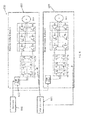
- the system 400 includes a generator 402 and a main controller 404 that are coupled to a pair of motor controllers 406, 408.
- the motor controllers 406, 408 each include active DC/AC motor controllers, an EMI filter 412 and a passive AC/DC converter.
- the motor controllers 406, 408 are powered from a single DC bus provided by the generator 402 and receive sets of PWM control signals from the main controller 404.
- the system 500 includes a generator 502 and a main controller 504 that are coupled to a pair of AC/AC motor controllers 506, 508.
- the motor controllers 506, 508 receive power from an AC/DC converter 510 and receive sets of PWM control signals from the main controller 504.
- the AC/DC converter 510 is coupled to the generator 502 via an EMI filter 512.
- the system 600 includes a generator 602 and a main controller 604 that are coupled to a pair of AC/AC motor controllers 606, 608.
- the motor controllers 606, 608 each include active AC/DC converters, active DC/AC converters, and an EMI filter 612.
- the motor controllers 606, 608 are powered from a single DC bus provided by the generator 602 and receive sets of PWM control signals from the main controller 604. The commands for both the AC/DC and DC/AC converters are interleaved.
Landscapes
- Engineering & Computer Science (AREA)
- Power Engineering (AREA)
- Mechanical Engineering (AREA)
- Transportation (AREA)
- Aviation & Aerospace Engineering (AREA)
- Control Of Multiple Motors (AREA)
- Electric Propulsion And Braking For Vehicles (AREA)
Applications Claiming Priority (1)
| Application Number | Priority Date | Filing Date | Title |
|---|---|---|---|
| US13/859,950 US8866326B1 (en) | 2013-04-10 | 2013-04-10 | Interleaved motor controllers for an electric taxi system |
Publications (3)
| Publication Number | Publication Date |
|---|---|
| EP2793389A2 true EP2793389A2 (de) | 2014-10-22 |
| EP2793389A3 EP2793389A3 (de) | 2015-04-01 |
| EP2793389B1 EP2793389B1 (de) | 2018-06-06 |
Family
ID=50543424
Family Applications (1)
| Application Number | Title | Priority Date | Filing Date |
|---|---|---|---|
| EP14163206.7A Active EP2793389B1 (de) | 2013-04-10 | 2014-04-02 | Verschachtelte Motorsteuerungen für elektrisches Taxisystem |
Country Status (2)
| Country | Link |
|---|---|
| US (1) | US8866326B1 (de) |
| EP (1) | EP2793389B1 (de) |
Families Citing this family (2)
| Publication number | Priority date | Publication date | Assignee | Title |
|---|---|---|---|---|
| JP6237938B1 (ja) * | 2016-10-18 | 2017-11-29 | 株式会社安川電機 | 多軸モータ制御システム、モータ制御装置、及びモータ制御方法 |
| WO2019170247A1 (en) * | 2018-03-09 | 2019-09-12 | Abb Schweiz Ag | Time-spread control cycles for robotic servomotors |
Family Cites Families (42)
| Publication number | Priority date | Publication date | Assignee | Title |
|---|---|---|---|---|
| JPS5846895A (ja) * | 1981-09-14 | 1983-03-18 | Hitachi Ltd | 誘導電動機のインバ−タ制御方式 |
| US5382890A (en) * | 1993-02-17 | 1995-01-17 | Pitney Bowes Inc. | Integrated circuit driver having current limiter for brushless motor |
| GB9408075D0 (en) * | 1994-04-22 | 1994-06-15 | Greenlite Limited | Improvements in or relating to aircraft |
| JP3271478B2 (ja) * | 1995-07-19 | 2002-04-02 | 松下電器産業株式会社 | 電流指令型pwmインバータ |
| US5675464A (en) * | 1996-05-02 | 1997-10-07 | Siemens Electric Limited | Stall or reduced-speed protection system for electric motor |
| FR2752111B1 (fr) * | 1996-07-30 | 1998-10-30 | Texas Instruments France | Procede et dispositif de commande d'onduleurs |
| JP3697623B2 (ja) * | 1997-05-30 | 2005-09-21 | アイシン精機株式会社 | チョッピング通電制御装置 |
| US5917721A (en) * | 1997-11-21 | 1999-06-29 | Allen-Bradley Company, Llc | Apparatus for reducing the effects of turn on delay errors in motor control |
| JPH11341878A (ja) * | 1998-05-29 | 1999-12-10 | Matsushita Electric Ind Co Ltd | 電動機制御装置 |
| US6222332B1 (en) * | 1999-09-16 | 2001-04-24 | Honeywell International Inc. | Low cost high performance single board motor controller |
| JP2001147243A (ja) * | 1999-11-24 | 2001-05-29 | Mitsubishi Electric Corp | アナログ信号検出回路及び半導体電力変換装置の交流側電流検出器 |
| US6324085B2 (en) * | 1999-12-27 | 2001-11-27 | Denso Corporation | Power converter apparatus and related method |
| JP4575547B2 (ja) * | 2000-04-18 | 2010-11-04 | トヨタ自動車株式会社 | モータの制御装置 |
| US7230401B2 (en) * | 2002-03-27 | 2007-06-12 | Brother Kogyo Kabushiki Kaisha | Apparatus and method for controlling an electric motor |
| US7002315B2 (en) * | 2002-05-28 | 2006-02-21 | Toshiba Kikai Kabushiki Kaisha | Servo control device |
| US7321210B2 (en) * | 2005-04-05 | 2008-01-22 | International Rectifier Corporation | Sensorless brushless direct current motor drive using pulse width modulation speed control at motor frequency |
| US7193385B2 (en) * | 2005-04-26 | 2007-03-20 | Illinois Institute Of Technology | Digital control of motor drives |
| JP4285458B2 (ja) * | 2005-08-08 | 2009-06-24 | トヨタ自動車株式会社 | 車両の電源装置およびその制御方法 |
| JP4839722B2 (ja) * | 2005-08-08 | 2011-12-21 | トヨタ自動車株式会社 | 車両の電源装置 |
| JP4517994B2 (ja) * | 2005-09-29 | 2010-08-04 | トヨタ自動車株式会社 | 充電制御装置および電動車両 |
| JP2007129787A (ja) * | 2005-11-01 | 2007-05-24 | Matsushita Electric Ind Co Ltd | モータ駆動装置 |
| JP4830462B2 (ja) * | 2005-11-18 | 2011-12-07 | トヨタ自動車株式会社 | 電動車両の制御装置 |
| JP4491434B2 (ja) * | 2006-05-29 | 2010-06-30 | トヨタ自動車株式会社 | 電力制御装置およびそれを備えた車両 |
| US7541760B2 (en) * | 2007-03-13 | 2009-06-02 | Sentelic Corporation | Method capable of controlling brushless DC motor |
| US7538505B2 (en) * | 2007-05-01 | 2009-05-26 | Alberkrack Jade H | Noise suppresion suppression for hall sensor arrangements |
| US7923944B2 (en) * | 2007-06-06 | 2011-04-12 | GM Global Technology Operations LLC | Single processor dual motor control |
| US8421393B2 (en) * | 2007-10-19 | 2013-04-16 | Lockheed Martin Corporation | System and method for pulse edge synchronization |
| US8084972B2 (en) * | 2007-11-16 | 2011-12-27 | Honeywell International Inc. | Dual lane control of a permanent magnet brushless motor using non-trapezoidal commutation control |
| JP5305796B2 (ja) * | 2008-09-09 | 2013-10-02 | 株式会社東芝 | モータ制御装置,モータ駆動システム,ポンプ装置並びにモータ制御方法 |
| JP4730420B2 (ja) * | 2008-10-09 | 2011-07-20 | トヨタ自動車株式会社 | モータ駆動装置およびモータ駆動装置の制御方法 |
| JP5002568B2 (ja) * | 2008-10-29 | 2012-08-15 | 日立オートモティブシステムズ株式会社 | 電力変換装置 |
| DE102009018143A1 (de) * | 2009-04-08 | 2010-10-14 | Aesculap Ag | Chirurgische Motorsteuerungs- und/oder -regelungsvorrichtung, chirurgisches Antriebssystem und Verfahren zum Steuern und/oder Regeln einer chirurgischen Antriebseinheit |
| US8493010B2 (en) * | 2009-04-22 | 2013-07-23 | Texas Instruments Incorporated | Quiet motor control system |
| WO2011099122A1 (ja) * | 2010-02-10 | 2011-08-18 | 株式会社 日立製作所 | 電力変換装置 |
| JP2011234517A (ja) * | 2010-04-28 | 2011-11-17 | Renesas Electronics Corp | 動力駆動制御装置および動力装置 |
| CN102959855B (zh) * | 2010-06-25 | 2015-01-21 | 丰田自动车株式会社 | 马达驱动装置和搭载该马达驱动装置的车辆 |
| WO2012029451A1 (ja) * | 2010-09-02 | 2012-03-08 | 日立オートモティブシステムズ株式会社 | 同期電動機の駆動システム |
| US9033273B2 (en) * | 2010-11-02 | 2015-05-19 | Jonathan Edelson | Integrated aircraft ground navigation control system |
| FR2968274B1 (fr) * | 2010-12-06 | 2013-02-01 | Messier Bugatti | Dispositif de freinage/entrainement d'une roue d'aeronef. |
| JP5784313B2 (ja) * | 2011-01-20 | 2015-09-24 | ナブテスコ株式会社 | モータ制御装置及びモータ制御システム |
| MX341538B (es) * | 2011-12-31 | 2016-08-24 | Broad-Ocean Motor Ev Co Ltd | Circuito de filtro de pulsos angostos con compensacion automatica y controlador de motor que lo aplica. |
| JP6013031B2 (ja) * | 2012-06-08 | 2016-10-25 | ナブテスコ株式会社 | 三相交流モータの駆動制御装置及びアクチュエータの油圧システム |
-
2013
- 2013-04-10 US US13/859,950 patent/US8866326B1/en active Active
-
2014
- 2014-04-02 EP EP14163206.7A patent/EP2793389B1/de active Active
Non-Patent Citations (1)
| Title |
|---|
| None |
Also Published As
| Publication number | Publication date |
|---|---|
| US20140306452A1 (en) | 2014-10-16 |
| EP2793389A3 (de) | 2015-04-01 |
| EP2793389B1 (de) | 2018-06-06 |
| US8866326B1 (en) | 2014-10-21 |
Similar Documents
| Publication | Publication Date | Title |
|---|---|---|
| US20250353602A1 (en) | Propulsion system and methods of use thereof | |
| US11542021B2 (en) | Aircraft propulsion system | |
| US10730633B2 (en) | Hybrid electric aircraft propulsion system with motors using induction effect | |
| US20210281210A1 (en) | Aircraft drive system | |
| US20130147204A1 (en) | Hybrid Drive And Energy System For Aircraft | |
| CN110829806A (zh) | 飞行器通用电力转换器 | |
| GB2539547A (en) | Aircraft electrical network | |
| RU2690779C1 (ru) | Электрическая система руления летательного аппарата и способ для управления системой | |
| CN108602564A (zh) | 用于驱动飞行器的方法和飞行器 | |
| CN102686479B (zh) | 具有涡轮喷气发动机以及起落架的飞行器 | |
| AU2017410335A1 (en) | Electric drive train and method for feeding an electric drive train | |
| WO2009057388A1 (ja) | 電動機制御装置,電気自動車およびハイブリッド電気自動車 | |
| EP2928068A3 (de) | Systeme mit steuerbarem Spannungs-Wechselstromgeneratorsystem | |
| US8866326B1 (en) | Interleaved motor controllers for an electric taxi system | |
| US20150375855A1 (en) | Method for managing an electric motor | |
| CN105035320A (zh) | 一种多旋翼垂直起降的固定翼飞行器 | |
| EP2345149A1 (de) | Leistungsverteilungs-vorrichtung zum verteilen von leistung und verfahren zum verteilen von leistung | |
| EP3778401A1 (de) | Rollen eines flugzeugs mit hybridantrieb | |
| CN102195505A (zh) | 与车辆电动机相连的逆变器的不连续脉宽调制的使用 | |
| US8421393B2 (en) | System and method for pulse edge synchronization | |
| US10479511B2 (en) | Direct current (DC) deicing control system, a DC deicing system and an aircraft including a DC deicing system | |
| EP3931091B1 (de) | Verteilte antriebskonfigurationen für flugzeug mit gemischten antriebssystemen | |
| GB2588710A (en) | Vortex turbines for a hybrid-electric aircraft | |
| CA3132260A1 (en) | Aircraft propulsion system having hybrid-electric powerplant and combustion powerplant | |
| EP4398464A1 (de) | Stromrichter für ein elektrisches energiesystem |
Legal Events
| Date | Code | Title | Description |
|---|---|---|---|
| PUAI | Public reference made under article 153(3) epc to a published international application that has entered the european phase |
Free format text: ORIGINAL CODE: 0009012 |
|
| 17P | Request for examination filed |
Effective date: 20140402 |
|
| AK | Designated contracting states |
Kind code of ref document: A2 Designated state(s): AL AT BE BG CH CY CZ DE DK EE ES FI FR GB GR HR HU IE IS IT LI LT LU LV MC MK MT NL NO PL PT RO RS SE SI SK SM TR |
|
| AX | Request for extension of the european patent |
Extension state: BA ME |
|
| PUAL | Search report despatched |
Free format text: ORIGINAL CODE: 0009013 |
|
| AK | Designated contracting states |
Kind code of ref document: A3 Designated state(s): AL AT BE BG CH CY CZ DE DK EE ES FI FR GB GR HR HU IE IS IT LI LT LU LV MC MK MT NL NO PL PT RO RS SE SI SK SM TR |
|
| AX | Request for extension of the european patent |
Extension state: BA ME |
|
| RIC1 | Information provided on ipc code assigned before grant |
Ipc: B64C 25/40 20060101ALI20150220BHEP Ipc: H02M 1/42 20070101ALI20150220BHEP Ipc: H02P 5/74 20060101AFI20150220BHEP |
|
| R17P | Request for examination filed (corrected) |
Effective date: 20150929 |
|
| RBV | Designated contracting states (corrected) |
Designated state(s): AL AT BE BG CH CY CZ DE DK EE ES FI FR GB GR HR HU IE IS IT LI LT LU LV MC MK MT NL NO PL PT RO RS SE SI SK SM TR |
|
| STAA | Information on the status of an ep patent application or granted ep patent |
Free format text: STATUS: EXAMINATION IS IN PROGRESS |
|
| 17Q | First examination report despatched |
Effective date: 20170216 |
|
| GRAP | Despatch of communication of intention to grant a patent |
Free format text: ORIGINAL CODE: EPIDOSNIGR1 |
|
| STAA | Information on the status of an ep patent application or granted ep patent |
Free format text: STATUS: GRANT OF PATENT IS INTENDED |
|
| INTG | Intention to grant announced |
Effective date: 20171222 |
|
| GRAS | Grant fee paid |
Free format text: ORIGINAL CODE: EPIDOSNIGR3 |
|
| GRAA | (expected) grant |
Free format text: ORIGINAL CODE: 0009210 |
|
| STAA | Information on the status of an ep patent application or granted ep patent |
Free format text: STATUS: THE PATENT HAS BEEN GRANTED |
|
| AK | Designated contracting states |
Kind code of ref document: B1 Designated state(s): AL AT BE BG CH CY CZ DE DK EE ES FI FR GB GR HR HU IE IS IT LI LT LU LV MC MK MT NL NO PL PT RO RS SE SI SK SM TR |
|
| REG | Reference to a national code |
Ref country code: GB Ref legal event code: FG4D |
|
| REG | Reference to a national code |
Ref country code: CH Ref legal event code: EP Ref country code: AT Ref legal event code: REF Ref document number: 1007138 Country of ref document: AT Kind code of ref document: T Effective date: 20180615 |
|
| REG | Reference to a national code |
Ref country code: IE Ref legal event code: FG4D |
|
| REG | Reference to a national code |
Ref country code: DE Ref legal event code: R096 Ref document number: 602014026546 Country of ref document: DE |
|
| REG | Reference to a national code |
Ref country code: NL Ref legal event code: MP Effective date: 20180606 |
|
| REG | Reference to a national code |
Ref country code: LT Ref legal event code: MG4D |
|
| PG25 | Lapsed in a contracting state [announced via postgrant information from national office to epo] |
Ref country code: BG Free format text: LAPSE BECAUSE OF FAILURE TO SUBMIT A TRANSLATION OF THE DESCRIPTION OR TO PAY THE FEE WITHIN THE PRESCRIBED TIME-LIMIT Effective date: 20180906 Ref country code: FI Free format text: LAPSE BECAUSE OF FAILURE TO SUBMIT A TRANSLATION OF THE DESCRIPTION OR TO PAY THE FEE WITHIN THE PRESCRIBED TIME-LIMIT Effective date: 20180606 Ref country code: NO Free format text: LAPSE BECAUSE OF FAILURE TO SUBMIT A TRANSLATION OF THE DESCRIPTION OR TO PAY THE FEE WITHIN THE PRESCRIBED TIME-LIMIT Effective date: 20180906 Ref country code: LT Free format text: LAPSE BECAUSE OF FAILURE TO SUBMIT A TRANSLATION OF THE DESCRIPTION OR TO PAY THE FEE WITHIN THE PRESCRIBED TIME-LIMIT Effective date: 20180606 Ref country code: ES Free format text: LAPSE BECAUSE OF FAILURE TO SUBMIT A TRANSLATION OF THE DESCRIPTION OR TO PAY THE FEE WITHIN THE PRESCRIBED TIME-LIMIT Effective date: 20180606 Ref country code: SE Free format text: LAPSE BECAUSE OF FAILURE TO SUBMIT A TRANSLATION OF THE DESCRIPTION OR TO PAY THE FEE WITHIN THE PRESCRIBED TIME-LIMIT Effective date: 20180606 Ref country code: CY Free format text: LAPSE BECAUSE OF FAILURE TO SUBMIT A TRANSLATION OF THE DESCRIPTION OR TO PAY THE FEE WITHIN THE PRESCRIBED TIME-LIMIT Effective date: 20180606 |
|
| PG25 | Lapsed in a contracting state [announced via postgrant information from national office to epo] |
Ref country code: LV Free format text: LAPSE BECAUSE OF FAILURE TO SUBMIT A TRANSLATION OF THE DESCRIPTION OR TO PAY THE FEE WITHIN THE PRESCRIBED TIME-LIMIT Effective date: 20180606 Ref country code: RS Free format text: LAPSE BECAUSE OF FAILURE TO SUBMIT A TRANSLATION OF THE DESCRIPTION OR TO PAY THE FEE WITHIN THE PRESCRIBED TIME-LIMIT Effective date: 20180606 Ref country code: GR Free format text: LAPSE BECAUSE OF FAILURE TO SUBMIT A TRANSLATION OF THE DESCRIPTION OR TO PAY THE FEE WITHIN THE PRESCRIBED TIME-LIMIT Effective date: 20180907 Ref country code: HR Free format text: LAPSE BECAUSE OF FAILURE TO SUBMIT A TRANSLATION OF THE DESCRIPTION OR TO PAY THE FEE WITHIN THE PRESCRIBED TIME-LIMIT Effective date: 20180606 |
|
| REG | Reference to a national code |
Ref country code: AT Ref legal event code: MK05 Ref document number: 1007138 Country of ref document: AT Kind code of ref document: T Effective date: 20180606 |
|
| PG25 | Lapsed in a contracting state [announced via postgrant information from national office to epo] |
Ref country code: NL Free format text: LAPSE BECAUSE OF FAILURE TO SUBMIT A TRANSLATION OF THE DESCRIPTION OR TO PAY THE FEE WITHIN THE PRESCRIBED TIME-LIMIT Effective date: 20180606 |
|
| PG25 | Lapsed in a contracting state [announced via postgrant information from national office to epo] |
Ref country code: EE Free format text: LAPSE BECAUSE OF FAILURE TO SUBMIT A TRANSLATION OF THE DESCRIPTION OR TO PAY THE FEE WITHIN THE PRESCRIBED TIME-LIMIT Effective date: 20180606 Ref country code: PL Free format text: LAPSE BECAUSE OF FAILURE TO SUBMIT A TRANSLATION OF THE DESCRIPTION OR TO PAY THE FEE WITHIN THE PRESCRIBED TIME-LIMIT Effective date: 20180606 Ref country code: AT Free format text: LAPSE BECAUSE OF FAILURE TO SUBMIT A TRANSLATION OF THE DESCRIPTION OR TO PAY THE FEE WITHIN THE PRESCRIBED TIME-LIMIT Effective date: 20180606 Ref country code: IS Free format text: LAPSE BECAUSE OF FAILURE TO SUBMIT A TRANSLATION OF THE DESCRIPTION OR TO PAY THE FEE WITHIN THE PRESCRIBED TIME-LIMIT Effective date: 20181006 Ref country code: SK Free format text: LAPSE BECAUSE OF FAILURE TO SUBMIT A TRANSLATION OF THE DESCRIPTION OR TO PAY THE FEE WITHIN THE PRESCRIBED TIME-LIMIT Effective date: 20180606 Ref country code: CZ Free format text: LAPSE BECAUSE OF FAILURE TO SUBMIT A TRANSLATION OF THE DESCRIPTION OR TO PAY THE FEE WITHIN THE PRESCRIBED TIME-LIMIT Effective date: 20180606 Ref country code: RO Free format text: LAPSE BECAUSE OF FAILURE TO SUBMIT A TRANSLATION OF THE DESCRIPTION OR TO PAY THE FEE WITHIN THE PRESCRIBED TIME-LIMIT Effective date: 20180606 |
|
| PG25 | Lapsed in a contracting state [announced via postgrant information from national office to epo] |
Ref country code: IT Free format text: LAPSE BECAUSE OF FAILURE TO SUBMIT A TRANSLATION OF THE DESCRIPTION OR TO PAY THE FEE WITHIN THE PRESCRIBED TIME-LIMIT Effective date: 20180606 Ref country code: SM Free format text: LAPSE BECAUSE OF FAILURE TO SUBMIT A TRANSLATION OF THE DESCRIPTION OR TO PAY THE FEE WITHIN THE PRESCRIBED TIME-LIMIT Effective date: 20180606 |
|
| REG | Reference to a national code |
Ref country code: DE Ref legal event code: R097 Ref document number: 602014026546 Country of ref document: DE |
|
| PLBE | No opposition filed within time limit |
Free format text: ORIGINAL CODE: 0009261 |
|
| STAA | Information on the status of an ep patent application or granted ep patent |
Free format text: STATUS: NO OPPOSITION FILED WITHIN TIME LIMIT |
|
| 26N | No opposition filed |
Effective date: 20190307 |
|
| PG25 | Lapsed in a contracting state [announced via postgrant information from national office to epo] |
Ref country code: DK Free format text: LAPSE BECAUSE OF FAILURE TO SUBMIT A TRANSLATION OF THE DESCRIPTION OR TO PAY THE FEE WITHIN THE PRESCRIBED TIME-LIMIT Effective date: 20180606 Ref country code: SI Free format text: LAPSE BECAUSE OF FAILURE TO SUBMIT A TRANSLATION OF THE DESCRIPTION OR TO PAY THE FEE WITHIN THE PRESCRIBED TIME-LIMIT Effective date: 20180606 |
|
| PG25 | Lapsed in a contracting state [announced via postgrant information from national office to epo] |
Ref country code: AL Free format text: LAPSE BECAUSE OF FAILURE TO SUBMIT A TRANSLATION OF THE DESCRIPTION OR TO PAY THE FEE WITHIN THE PRESCRIBED TIME-LIMIT Effective date: 20180606 |
|
| REG | Reference to a national code |
Ref country code: CH Ref legal event code: PL |
|
| REG | Reference to a national code |
Ref country code: BE Ref legal event code: MM Effective date: 20190430 |
|
| PG25 | Lapsed in a contracting state [announced via postgrant information from national office to epo] |
Ref country code: LU Free format text: LAPSE BECAUSE OF NON-PAYMENT OF DUE FEES Effective date: 20190402 Ref country code: MC Free format text: LAPSE BECAUSE OF FAILURE TO SUBMIT A TRANSLATION OF THE DESCRIPTION OR TO PAY THE FEE WITHIN THE PRESCRIBED TIME-LIMIT Effective date: 20180606 |
|
| PG25 | Lapsed in a contracting state [announced via postgrant information from national office to epo] |
Ref country code: LI Free format text: LAPSE BECAUSE OF NON-PAYMENT OF DUE FEES Effective date: 20190430 Ref country code: CH Free format text: LAPSE BECAUSE OF NON-PAYMENT OF DUE FEES Effective date: 20190430 |
|
| PG25 | Lapsed in a contracting state [announced via postgrant information from national office to epo] |
Ref country code: BE Free format text: LAPSE BECAUSE OF NON-PAYMENT OF DUE FEES Effective date: 20190430 |
|
| PG25 | Lapsed in a contracting state [announced via postgrant information from national office to epo] |
Ref country code: TR Free format text: LAPSE BECAUSE OF FAILURE TO SUBMIT A TRANSLATION OF THE DESCRIPTION OR TO PAY THE FEE WITHIN THE PRESCRIBED TIME-LIMIT Effective date: 20180606 |
|
| PG25 | Lapsed in a contracting state [announced via postgrant information from national office to epo] |
Ref country code: IE Free format text: LAPSE BECAUSE OF NON-PAYMENT OF DUE FEES Effective date: 20190402 |
|
| PG25 | Lapsed in a contracting state [announced via postgrant information from national office to epo] |
Ref country code: PT Free format text: LAPSE BECAUSE OF FAILURE TO SUBMIT A TRANSLATION OF THE DESCRIPTION OR TO PAY THE FEE WITHIN THE PRESCRIBED TIME-LIMIT Effective date: 20181008 |
|
| PG25 | Lapsed in a contracting state [announced via postgrant information from national office to epo] |
Ref country code: HU Free format text: LAPSE BECAUSE OF FAILURE TO SUBMIT A TRANSLATION OF THE DESCRIPTION OR TO PAY THE FEE WITHIN THE PRESCRIBED TIME-LIMIT; INVALID AB INITIO Effective date: 20140402 Ref country code: MT Free format text: LAPSE BECAUSE OF FAILURE TO SUBMIT A TRANSLATION OF THE DESCRIPTION OR TO PAY THE FEE WITHIN THE PRESCRIBED TIME-LIMIT Effective date: 20180606 |
|
| PG25 | Lapsed in a contracting state [announced via postgrant information from national office to epo] |
Ref country code: MK Free format text: LAPSE BECAUSE OF FAILURE TO SUBMIT A TRANSLATION OF THE DESCRIPTION OR TO PAY THE FEE WITHIN THE PRESCRIBED TIME-LIMIT Effective date: 20180606 |
|
| P01 | Opt-out of the competence of the unified patent court (upc) registered |
Effective date: 20230522 |
|
| PGFP | Annual fee paid to national office [announced via postgrant information from national office to epo] |
Ref country code: DE Payment date: 20250319 Year of fee payment: 12 |
|
| PGFP | Annual fee paid to national office [announced via postgrant information from national office to epo] |
Ref country code: GB Payment date: 20260319 Year of fee payment: 13 |
|
| PGFP | Annual fee paid to national office [announced via postgrant information from national office to epo] |
Ref country code: FR Payment date: 20260320 Year of fee payment: 13 |