EP2790601B1 - Implantable device with locking adjustment mechanism - Google Patents
Implantable device with locking adjustment mechanism Download PDFInfo
- Publication number
- EP2790601B1 EP2790601B1 EP12810498.1A EP12810498A EP2790601B1 EP 2790601 B1 EP2790601 B1 EP 2790601B1 EP 12810498 A EP12810498 A EP 12810498A EP 2790601 B1 EP2790601 B1 EP 2790601B1
- Authority
- EP
- European Patent Office
- Prior art keywords
- head
- proximal
- relative
- intramedullary rod
- fastener
- Prior art date
- Legal status (The legal status is an assumption and is not a legal conclusion. Google has not performed a legal analysis and makes no representation as to the accuracy of the status listed.)
- Active
Links
- GDOPTJXRTPNYNR-UHFFFAOYSA-N CC1CCCC1 Chemical compound CC1CCCC1 GDOPTJXRTPNYNR-UHFFFAOYSA-N 0.000 description 1
- JPWYYRCELICUKE-UHFFFAOYSA-N CCNC1CCC1 Chemical compound CCNC1CCC1 JPWYYRCELICUKE-UHFFFAOYSA-N 0.000 description 1
Images


Classifications
-
- A—HUMAN NECESSITIES
- A61—MEDICAL OR VETERINARY SCIENCE; HYGIENE
- A61B—DIAGNOSIS; SURGERY; IDENTIFICATION
- A61B17/00—Surgical instruments, devices or methods
- A61B17/56—Surgical instruments or methods for treatment of bones or joints; Devices specially adapted therefor
- A61B17/58—Surgical instruments or methods for treatment of bones or joints; Devices specially adapted therefor for osteosynthesis, e.g. bone plates, screws or setting implements
- A61B17/68—Internal fixation devices, including fasteners and spinal fixators, even if a part thereof projects from the skin
- A61B17/72—Intramedullary devices, e.g. pins or nails
- A61B17/7233—Intramedullary devices, e.g. pins or nails with special means of locking the nail to the bone
- A61B17/7241—Intramedullary devices, e.g. pins or nails with special means of locking the nail to the bone the nail having separate elements through which screws pass
-
- A—HUMAN NECESSITIES
- A61—MEDICAL OR VETERINARY SCIENCE; HYGIENE
- A61B—DIAGNOSIS; SURGERY; IDENTIFICATION
- A61B17/00—Surgical instruments, devices or methods
- A61B17/56—Surgical instruments or methods for treatment of bones or joints; Devices specially adapted therefor
- A61B17/58—Surgical instruments or methods for treatment of bones or joints; Devices specially adapted therefor for osteosynthesis, e.g. bone plates, screws or setting implements
- A61B17/68—Internal fixation devices, including fasteners and spinal fixators, even if a part thereof projects from the skin
- A61B17/74—Devices for the head or neck or trochanter of the femur
- A61B17/742—Devices for the head or neck or trochanter of the femur having one or more longitudinal elements oriented along or parallel to the axis of the neck
- A61B17/744—Devices for the head or neck or trochanter of the femur having one or more longitudinal elements oriented along or parallel to the axis of the neck the longitudinal elements coupled to an intramedullary nail
-
- A—HUMAN NECESSITIES
- A61—MEDICAL OR VETERINARY SCIENCE; HYGIENE
- A61B—DIAGNOSIS; SURGERY; IDENTIFICATION
- A61B17/00—Surgical instruments, devices or methods
- A61B17/56—Surgical instruments or methods for treatment of bones or joints; Devices specially adapted therefor
- A61B17/58—Surgical instruments or methods for treatment of bones or joints; Devices specially adapted therefor for osteosynthesis, e.g. bone plates, screws or setting implements
- A61B17/68—Internal fixation devices, including fasteners and spinal fixators, even if a part thereof projects from the skin
- A61B17/74—Devices for the head or neck or trochanter of the femur
- A61B17/742—Devices for the head or neck or trochanter of the femur having one or more longitudinal elements oriented along or parallel to the axis of the neck
- A61B17/748—Devices for the head or neck or trochanter of the femur having one or more longitudinal elements oriented along or parallel to the axis of the neck with means for adapting the angle between the longitudinal elements and the shaft axis of the femur
Definitions
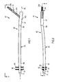
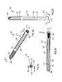
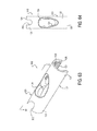
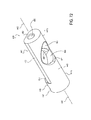
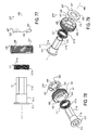
- the apparatus 61 comprises an intramedullary rod 62 and a proximal fastener 63 pivotably carried by the proximal portion of the rod (see FIGS. 1-3 ).
- the proximal fastener 63 can be of any suitable type, including a fixation screw, a screw, a peg, a helical blade or any other fixation device, and for simplicity is referred to herein as a fixation screw.
- the femoral nail or rod 62 includes an elongate body 64 that extends along a longitudinal axis 66 and can have a proximal portion or head 67, a central portion or neck 68 and a distal portion or shaft 69 that terminates at a distal tip 71.
- the elongate body 64 may curve in at least one portion of the shaft or stem 69 to align the rod 62 along the length of the marrow canal of the femur when the rod is inserted in the femur.
- the elongate body 64 can be made from any suitable material such as stainless steel, titanium or another alloy and can have a length, dependent in part on the length in which the rod 62 is to be utilized, ranging from 180 to 500 centimeters.
- the head 67 of the nail 62 can have a length ranging from four to 15 centimeters and preferably ranging from eight to 12 centimeters and a diameter ranging from eight to 20 millimeters.
- the distal-most bore 81 is elongated in its transverse direction, that is parallel to the longitudinal axis 66 of the stem 69, to permit the stem to be moved longitudinally relative to the respective distal fastener or fixation screw 82 before tightening of the fastener or screw to the underlying portion of the femur.
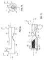
- At least one transverse apertures or opening 91 is provided through the head 67 of the rod 62 and in one example is angled toward the proximal end of the rod relative to longitudinal axis 66 for receiving the proximal fixation screw or fixation screw 63. More specifically, the one or more transverse apertures or holes 91 each pivotably receive a fixation screw 63 and allow for changing the angle made between the screw 63 and the nail 62. Each such aperture or first hole can extend through the head 67 in an angled direction relative to longitudinal axis 66 such that when the rod is in position within the marrow canal of the femur, axis 92 of the opening is directed toward the head of the femur (see FIG. 13 ). As can be seen from FIGS.
- the transverse aperture or aperture 92 in the head 67 can communicate with a first or lateral transverse opening 93, through which the respective fixation screw is inserted, and an opposite second or medial transverse opening 94, from which the distal portion of the screw extends.
- the medial transverse opening 94 as shown in FIGS. 5 , 8 , 11 and 13 , can be elongate or oblong in a transverse direction that is parallel to longitudinal axis 66 of head 67 and body 64, so as to accommodate pivoting of the distal portion of the proximal fixation screw 63.
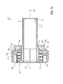
- Internal threads 104 can be provided in proximal portion 102a.
- the segmented circular portion or segmented portion 102b of recess 102 may be formed from an inner arcuate surface 105.
- the other side of the recess 102, that is the side opposite of segmented portion 102b, can be formed with a first shelf 107, a second shelf 108 and a third shelf 109 that can each extend further radially inwardly than the inner arcuate surface 105 of the segmented portion 102b and can have increasingly smaller radii relative to longitudinal axis 66 (see FIGS. 11-13 ).
- the proximal portion of the first shelf 107 can be optionally provided with internal threads 111, as shown in FIGS. 4 , 9 and 10 .
- a shoulder 112 can extend radially inwardly from first shelf 107 to second shelf 108 (see FIG. 13 ).
- the third shelf 109 may abut the lateral transverse opening 93, as shown in FIG. 11 .
- Transversely aligned slots 110 may be provided on the proximal end of head 67 at proximal opening 103 for registering the nail 62 with an insertion jig, targeting device or other suitable device when placing or otherwise manipulating the nail within the targeted bone.
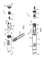
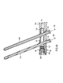
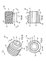
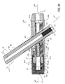
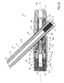
- the actuation or adjustment mechanism 101 for pivoting the proximal fixation screw 63 can be of any suitable type, in one example the mechanism 101 includes an insert or sleeve 116, a control element 117, an end or safety nut 118 and an alignment or set screw 119, as shown in the exploded views of FIGS. 5-6 and in the assembled view of FIG. 4 .
- Each of these components can be made from any suitable material such as stainless steel.
- Such transverse, cross-sectional configuration of sleeve 116 preferably approximates the cross-sectional configuration of the segmented circular portion 102b of the recess 102 in head 67 and can extend through an arc ranging from 100 to 360 degrees, preferably ranging from 180 to 240 degrees and illustrated in FIG. 16 as approximately 240 degrees.
- the elongate transverse opening 124 can be formed in the center of the insert. Such opening 124 may be oblong or elongate in shape and smaller than the medial transverse opening 94 provided in head 67 of the nail 62.
- the insert 116 may be provided with internal thread 131 extending through the bore 127 at the proximal portion 122 of the insert, such threads being adjacent the top or proximal end of the insert as shown in FIGS. 14 and 17 .
- the insert can have a length ranging from 30 to 110 millimeters and can have an external radius sized to fit within head 67 of the nail 62.
- the distal portion of internal bore 127 that is the portion of the bore distal transverse opening 124, has a smaller internal diameter than the internal diameter of the proximal portion of the bore.
- Control element 117 can be of any suitable type and in one example includes a spindle or screw 117 formed from a cylindrical body 136 provided with a distal portion 137 of constant radius and can have a smooth outer cylindrical surface 138, a central portion 139 adjacent the distal portion and having external threads 141 extending radially outwardly relative to the distal portion and a proximal or neck portion 142 adjacent the central portion (see FIGS. 18-22 ).
- the neck portion can include a proximal flange 143 and an annular recess 144 disposed between the flange and the central portion 139 of the spindle or screw 117.
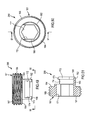
- the distal end portion of the end nut may be provided with a recess or socket 172 that can be in communication with bore 171 and be side opening onto the outer cylindrical surface 163 of the distal portion 162.
- the socket 172 can be sized and configured for cooperatively receiving the neck portion 142 of the spindle 117 and may include a partial annular flange 173, shown most clearly in FIG. 24 , extending radially inwardly for partially seating in the annular recess 144 of the spindle and a partial annular recess 174 extending radially outwardly relative to the flange for receiving part of the proximal, annular flange 143 of the spindle.
- the end nut can have a length ranging from five to 50 millimeters and preferably approximately 15 millimeters.
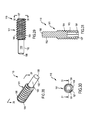
- the proximal portion 202 may be provided with a plurality and as shown four longitudinally-extending slots 204 extending through the surface 203 in circumferentially-spaced apart positions.
- Distal portion 206 of the body 201 may be provided with external threads 207 that extend to a sharpened distal end or tip 208 of the body.
- the distal portion 206 of the body 207 may be irregularly shaped or flat (not shown).
- the body can further have a proximal end 211 and be provided with a central bore 212 that extends longitudinally through the body from the proximal end 211 to the distal end 208 (see FIG. 35 ).
- the proximal end of the central bore 212 may be provided with internal threads 213 and be formed with a drive socket 214 of any suitable type for facilitating connection of the proximal fixation screw to a drive tool of any suitable type.
- the distal end of the transverse opening 124 in the insert 116 engages the fixation screw during proximal movement of the insert within the head 67 to cause the fixation screw to pivot within the medial transverse opening 93 of the transverse aperture 91 of the head.
- the spindle 117 can rotate freely relative to the head and the end cap 118.
- the set screw 119 can be rotated distally with the spindle 117 so that the blunted end 188 of the set screw seats within one of the longitudinal slots 294 formed in the proximal portion 202 of the fixation screw 63 so as to rotatably lock the fixation screw relative to the head 67 of the intramedullary rod 62 and thus inhibit undesirable further advancement or withdrawal of the screw 63 relative to the rod 62.
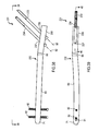
- FIGS. 38-52 Another apparatus 231 is illustrated in FIGS. 38-52 and can include an intramedullary rod 232 substantially similar to rod 62. Like reference numerals have been utilized to describe like components of rods 62 and 232.
- the intramedullary rod 232 has any suitable first and second proximal fasteners, shown as first and second proximal fixation screws 233 and 234 that can each be substantially identical to proximal fixation screw 63, pivotably received within respective first and second transverse apertures 236 and 237 that can each be substantially identical to transverse aperture 91 and extend along respective axes 92.
- the first and second fasteners 233 and 234 extend parallel to each other, may or may not be of the same length and may or may not be of the same type of fastener.
- the first fastener 233 may be a screw and the second fastener 234 may be a peg or blade.
- the apertures 236 and 237 are provided in a head 239, substantially similar to head 67, of the rod 232.
- the insert 242 can have a length ranging from 20 to 120 millimeters and an external radius sized to fit within head 239 of the nail 232.
- a spindle 256 can be provided that is substantially similar to the spindle 117 but formed without the distal portion 137 of spindle 117 (see FIGS. 45-48 ). Instead, spindle 256 of the dual fixation screw rod 232 of FIGS. 38-52 has a proximal or neck portion 142 and a distal portion 257 substantially similar to central portion 139 of the spindle 117.
- the spindle 256 can have a length ranging from five to 30 millimeters.
- An end cap or nut 266 substantially similar to end nut 118 but shorter in length can be further provided (see FIGS.
- actuation assembly 241 can be loaded into head 239 of dual fixation screw rod 232, and operated therein with respect to first and second proximal fixation screws 233 and 234, in substantially the same manner as discussed above with respect to apparatus 61.
- Sleeve 242 is shown in FIG. 40 in its distal position.
- the inclusion in apparatus 241 of the second fixation screw 234 minimizes the need for a set screw, such as set screw 119, and preferably eliminates the need for such a set screw.
- the second proximal fixation screw is included in the means or mechanism of the rod 232 for preventing rotation of the head of the femur relative to the first proximal fixation screw 233 during use of rod 232.
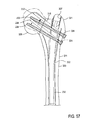
- FIG. 53 A further example of the intramedullary rod with pivotable fasteners is illustrated in FIG. 53 wherein an apparatus 271 substantially similar to apparatus 61 and 231 is provided. Like reference numerals have been used to describe like components of apparatus 61, 231 and 271.
- Intramedullary rod or nail 272 of the apparatus 271 is substantially similar to rods 62 and 232 and has any suitable first and second proximal fasteners, shown as first and second proximal fixation screws 233 and 234.
- the first screw 233 is pivotably received within first transverse aperture 236 extending along axis 92.
- the second screw 234 is pivotably received within a second transverse aperture 273 extending along an axis 274.
- the third proximal fixation screw 283 can be identical to one or both of first and second proximal fixation screws 233 and 234, and the third transverse aperture 286 can be identical to one or both of first and second transverse apertures 236 and 237.
- the first, second and third fasteners 233, 234 and 283 may or may not extend parallel to each other, may or may not be of the same length and may or may not be of the same type of fastener. In the illustrated example, the fasteners 233, 234 and 283 extend parallel to each other.
- the apertures 236, 237 and 286 are provided in a head 287 of the rod 282 that is substantially similar to head 239 of rod 232.
- An actuation mechanism or assembly substantially similar to actuation mechanism 241 but modified to provide for the third transverse aperture 286 can be provided.
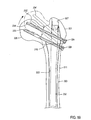
- FIGS. 55-56 Yet a further example of the intramedullary rod with pivotable fasteners is illustrated in FIGS. 55-56 wherein an apparatus 296 substantially similar to apparatus 61 and 231 is provided. Like reference numerals have been used to describe like components of apparatus 61, 231 and 296.
- Intramedullary rod or nail 297 of the apparatus 296 is substantially similar to rods 62 and 232 and has any suitable first and second proximal fasteners, shown as first and second proximal fixation screws 233 and 234.
- the first screw 233 is pivotably received within first transverse aperture 236 extending along axis 92.
- the second screw 234 is pivotably received within a second transverse aperture 298 extending along an axis 299.
- the second fixation screw 234 inhibits, if not prevents, rotation of the femoral head 326 relative to the first fixation screw 233.
- the apparatus can include more than two proximal fasteners to fixate head 326 of the femur, or a portion of any other suitable bone.
- Second fixation screw 333 and thus second aperture 341 can be proximal or distal or first aperture 91 and is shown as being distal of the first aperture 91. It is appreciated that a second or fixed fixation screw can be provided both proximally and distally of the one or more pivotable fixation screws, between the pivotable fixation screws or any combination of the foregoing. In one example, the second aperture 341 is located distally of the first aperture a distance ranging from two to 30 millimeters side to side and in another example a distance of approximately seven millimeters side to side.
- the second proximal fixation screw 333 can be disposed at any suitable angle ⁇ relative to longitudinal axis 66 of the elongate body 64.
- the screw 333 can be inclined proximally, as shown in FIGS. 60-62 , be inclined distally (not shown) or be orthogonal to the axis 66.
- the screw 333 is inclined relative to axis 66 at an angle ⁇ ranging from 90° to 170° and in another example at an angle ⁇ ranging from 120° to 140° (see FIG. 62 ).
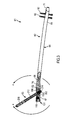
- Apparatus 31 can be used in any suitable procedure for repairing a bone of a mammalian body, for example a femur in a leg.
- rod 332 is introduced through the greater trochanter 321 into the medullary canal 332 in the shaft 323 of the femur 311.
- Suitable holes 324 are made in the side of the greater trochanter to allow insertion of the first and second fixation screws 63 and 333 into respective first and second apertures 91 and 346 of the rod 332.
- First screw 63 can be initially introduced through rod 332 and screwed into the head 326 of the femur 311.
- the fixed screw 333 can be further advanced relative to the head 348 of the rod 332 so as to cause the first screw 63 to pivot relative to the head 348, for example to pivot the first screw 63 toward proximal opening 77 of the rod 332.
- an actuation mechanism 351 need not be provided when the fixed screw 333 is used solely as the means for pivoting the dynamic screw 63.
- the dynamic screw pivots freely relative to head 348 and is supported in its desired position by static screw 333, either solely or in combination with another suitable securement mechanism (not shown). It is also appreciated that other means can be provided for pivoting the dynamic screw 63.
- a locking mechanism for use with an implantable medical device.
- the locking mechanism can be utilized with any medical device having a rotatable, control, moveable or other element on the outside or inside thereof.
- the locking mechanism can be used with a threaded element, for example an internal or external threaded element of a medical device.
- the element can be an element for controlling another moveable element of a medical device, for example a control element coupled to a longitudinally moveable or slidable element of the medical device.
- the medical device is an implantable intramedullary rod.
- a first or lateral transverse opening 421 is provided on one side of wall 413 or first side portion 413a of the wall and a second or medial transverse opening 422 is provided on the other side of the wall 413 or second side portion 413b of the wall.
- At least one of the openings 421 and 422 can be elongate or oblong in a direction parallel to longitudinally axis 404 so as to facilitate pivoting of the fixation screw 63 relative to head 406 about an axis (not shown) extending orthogonally to longitudinally axis 404 and aperture axis 417.
- the lateral transverse opening 421 is so elongate or oblong.
- Axis 417 is centered on aperture 416 and can extend relative to longitudinal axis 404 at an angle and in one embodiment at an angle of approximately 140 degrees measured from the portion of head 406 distal of head aperture 416.
- Annulus forms the periphery of the proximal portion 441a, and of the elongate member 441, and is substantially circular in shape.
- Lip 447 extends around the periphery of the proximal portion 441a, but is provided with an opening or cutout 449 at the top thereof such that the lip 447 does not extend around the top of elongate member 441.
- Elongate member 441 is provided with an elongate cutout 451 extending distally of annulus 446, and the cutout 451 is formed by a flat 452 which is planar and parallel to central axis 442.
- a concave arcuate surface 453 extends from each side of the flat 452 to bottom surface 443.
- distal portion 441b of the sleeve 436 is noncircular in cross section and in one embodiment its segmented circular cross section, as described above, corresponds generally with the cross section of segmented portion 412c of the head proximal recess 412.
- Distal portion 441b of the elongate member 441 is sized and shaped to slidably move longitudinally within segmented circular portion 412c of the proximal recess 412 of the head 406.
- Annulus 446 of the sleeve of 436 is externally sized and shaped to slidably move longitudinally move within central portion 412b of the head proximal recess 412.
- At least one of the openings 463 and 464 can be elongate or oblong in a direction parallel to central axis 442 so as to facilitate pivoting of the fixation screw 63 relative to head 406 and sleeve 436 about an axis (not shown) extending orthogonally to sleeve central axis 442 and aperture axis 462.
- medial transverse opening 464 is so provided with a cutout at its distal portion so as to be elongate or oblong.
- Axis 462 can be centered on aperture 461 and can extend relative to central axis 442 at an angle and in one embodiment at the same angle that axis 417 extends relative to longitudinal axis 404.
- worm gear 437 can be rotated in a clockwise direction from proximal opening 10.3 so as to cause sleeve 436 to move distally within the head 406, and rotated in a counter-clockwise direction from proximal opening 103 so as to cause the sleeve 436 to move proximally within the head 406.
- the diameter of drive socket 479 is larger than the diameter of the internally-threaded proximal portion of longitudinal bore 456 of the sleeve 439 and is preferably coaxially aligned with sleeve bore 456.
- Nut 486 has a distal surface 498 which includes flange 496 and in one embodiment the surface 498 is planar and orthogonal to central axis 488.
- a plurality of locking or engagement means or elements are provided on distal surface 498 and can be of any suitable type, including a plurality of recesses, protuberances or a combination of recesses and protuberances.
- such locking means includes a plurality of first upstanding protuberances or dogs 501 extending longitudinally outwardly from the distal surface 498.
- a plurality of first dogs 501 are spaced circumferentially around surface 498 and in one embodiment the first dogs 501 are circumferentially spaced equally apart around the distal surface 498.
- the second drive element 487 is annular in shape and can be an annular element.
- the second drive element can be in the form of a washer having opposite first and second planar surfaces 506, 507 extending parallel to each other and a bore 508 extending between the surfaces 506 and 507.
- the washer 487 has an outer diameter smaller than the inner diameter of threaded portion 412a of the head proximal recess 412. Similar to distal surface 498 of nut 486, first surface 506 of the washer is provided with a plurality of locking or engagement means or elements of any suitable type, including a plurality of recesses, protuberances or a combination of recesses and protuberances.
- such locking means include a plurality of second upstanding protuberances or dogs 509 extending longitudinally outwardly from the first surface 506.
- the plurality of second protuberances 509 are spaced circumferentially around the first surface 506 and in one embodiment the second dogs circumferentially spaced apart so as to register with or engage first dogs 501 and thus preclude relative to rotation between washer 47 and nut 46 when the washer 487 and second dogs 509 are in the first position. In this manner, second dogs 509 cooperatively engage first dogs 501 when washer 487 is in the first position.
- Locking mechanism 439 can further include a driver element or driver 511 having a proximal portion 511a with a circular outer surface and a distal portion or drive head 511b with an outer surface that is non-circular in cross section.
- the diameter or at least the distal portion of the circular outer surface approximates the diameter of the inner circular surface of nut flange 496.
- the cross-sectional shape of distal end or drive head 511b can be, for example, triangular, square, hexagonal or octagonal, and preferably corresponds in size and configuration and cooperates with drive socket 479 of the worm gear 437.
- a flange 512 extends radially outwardly from proximal portion 511a at the proximal end of driver 511.
- Flange 512 has an outer circular surface with a diameter that approximates the diameter of the inner circular surface 491 of nut 486.
- a drive socket 513 extends longitudinally inwardly from the proximal end of driver 511 and preferably has a cross section which is non-circular in shape, for example similar to the cross-sectional shape of drive head 511b discussed above, so that when the socket 513 is engaged by a suitable tool it can serve to cause rotation of the driver 511.
- a longitudinally-extending bore 514 extends distally from drive socket 513 through the remainder of the driver 511.
- driver 511 extends through nut 486 and washer 487. More specially, the driver 511 extends through bore 493 and flange 496 of the nut 486 until the nut flange 496 is in close proximity to driver proximal portion 511a and driver flange 512 is seated within bore 493 and in one embodiment flush with the proximal end of nut 486. In one embodiment, flange 496 of the nut engages the outer circular periphery of proximal portion 511a of the driver 511.
- Washer 487 extends around distal portion or end of driver proximal portion 511a distal of nut 46 so that when locking mechanism 439 is in its first or rest position second dogs 509 of washer 487 are cooperatively engaged and locked with first dogs 501 of nut 486.
- the washer 487 is secured to proximal portion 511 a of the driver by any suitable means such as welding. Nut 486 is not secured to driver 511 and thus longitudinally moveable relative to the driver.
- Locking mechanism 439 is movable between a first position in which driver 511 can rotate freely relative to nut 486 and a second position in which the driver 511 is rotatably locked with the nut 486.
- Spring 517 urges locking mechanism 439 towards its first or rest position, illustrated in FIGS. 76 and 82 , in which the springs 517 urges flange 512 of the driver 511 longitudinally away from flange 496 of nut 486 so that second dogs 509 on first surface 506 of washer 487 register and rotatably lock with first dogs 501 on distal surface 498 of the nut 46.
- driver 511 When driver 511 is urged longitudinally in a distal direction, for example by insertion of a suitable drive tool in drive socket 513 of the driver 511 and exertion of a longitudinal force in the distal direction on the tool and thus the driver 511, washer 487 that is rigidly secured proximal portion driver 511a of the driver is moved longitudinally against the force of spring 517 away from distal surface 498 of nut 486 so that the second dogs 509 of the washer 487 separate and disengage from first dogs 501 of the nut 46 to a second or disengaged position, illustrated in FIG. 83 , in which the combined driver 511 and washer 487 unit can be rotated relative to nut 486. As such, washer 487 is spaced longitudinally from nut 486 when the washer is in its second position.
- Set screw 438 can be of any suitable type and similar to set screw 119 discussed above.
- set screw 438 is cylindrical in conformation and externally threaded.
- the set screw 438 can include a rounded distal end 522 and a suitable drive socket 523 provided at its proximal end.
- Such set screw is diametrically sized so as to be capable of being passed longitudinally through drive socket 513 and bore 514 of drive 511 and into bore 456 of the sleeve 436 to threadably engage the threaded proximal portion 45ba of the sleeve bore 456.
- head 406 can be loaded in proximal recess 412 of the head in any suitable manner.
- sleeve 436 is introduced through threaded portion of 412a so that distal portion 441b of the sleeve is seated within segmented portion 412c of the recess 412 and annulus 446 of the sleeve is seated within central portion 412b of the recess 412.
- distal portion 441b has an external cross section similar to the internal cross section of segmented portion 412c so that sleeve 436 is rotatably locked but longitudinally movable or slidable in nail 402 relative to axis 404 of the nail.
- Aperture 461 of sleeve 436 is generally registered with aperture 416 of head 406 in the operational longitudinally positions of sleeve 436 within the nail head 406.
- nut 486 of the locking mechanism is secured to the head 406 and in one embodiment locked or secured against both rotatable and longitudinally movement within the head 406.
- the engaged invisible internal threads of threaded portion 412a of the head 406 and external threads at the proximal end of nut 486 are punched at one or more positions, for example at a plurality of circumferentially-spaced apart positions, by a suitable punching tool so as to preclude nut 46 from being rotatably moved in a proximal direction, and thus withdrawn, from threaded portion 412a of recess 412.
- Nail 402 can be placed within a bone in any suitable manner and for example as discussed above and as discussed below.
- a guide wire is first introduced into the bone and the nail is then threaded over the proximal end of the guide wire for proper placement and positioning in the bone.
- the proximal end of the guide wire can be inserted through passageway 76 of the elongate body 403, though adjustment mechanism 411 by means of bore 456 of sleeve 436 and drive socket 479 of worm gear 437, and through locking mechanism 439 by means of bore 514 and drive socket 513 of driver 511.
- the guide wire is removed from the nail 402 through proximal opening 103.
- a suitable fastener such fixation screw 63 can be introduced through head 406 by means of lateral transverse opening 421, aperture 461 of sleeve 436 and medial transverse opening 422 and properly positioned within the bone.
- lateral transverse opening 421 in first side portion 413a of wall 413 receives the proximal portion or head 67 of the fastener and medial transverse opening 422 in second side portion 413b of wall 413 receives the distal portion or shaft 69 of the fastener 63.
- fixation screw 63 can be pivoted relative to head 406 and central axis 404 through a range of angles by means of adjustment mechanism 411.
- the drive tool In order to rotatably unlock locking mechanism 439 and worm gear 437 that rotates one-to-one with driver 511 of the locking mechanism, so as to permit longitudinal movement of sleeve 437 within head 406, the drive tool is urged distally in drive socket 513 relative to head 406 so as to cause the driver 511 to move longitudinally along axis 404 and thus cause washer second dogs 509 to longitudinally separate and disengage from nut first dogs 501 in the manner discussed above.
- the drive tool can be used to rotate driver 511 freely of nut 486 and head 406 so as to rotate worm gear 437 and thus cause the worm gear and sleeve 436 coupled to the worm gear to move longitudinally within recess 412.
- the portion of the fixation screw 63 extending through aperture 461 of the elongate member 441 is constrained by sleeve 436, longitudinal movement of the sleeve relative to head 406 causes the fixation screw to pivot about medial transverse opening 422 of the head 406.
- Such structure also enhances retention of the fixation screw 63 in the desired angular position relative to nail head 406, for example after completion of the insertion and positioning of the nail 402 within a bone of a mammalian body and the head 326 of the bone is placed under load when the mammalian body is standing or walking so as to be urging head 326 of the bone into varus and thus exerting a moment on screw 63 in a clockwise direction in FIGS. 67 , 68 , 80 and 81 .
- rounded contact or support surface 428 of nail head 406 engages one side of the shaft 69 of screw 63 and rounded contact surface 471 of sleeve 436 engages the other side of the head 67 of screw 63 in longitudinally spaced apart positions along the length of the screw 63.
- the location of rounded contact surface 471 relatively close to the other side of nail head 406, and outer wall 413 of the head 406, from nail contact surface 428 provides a relatively large pivot arm for reducing the force exerted on each of surfaces 428 and 471.
- fixation screw 63 can be pivoted from a first or first extreme position, for example at an angle of approximately 120 degrees relative to head 406 of the nail 402 as shown in FIG. 68 , to an intermediate position, for example at an angle of approximately 130 degrees relative to head 406 as shown in FIG. 80 , to a second or second extreme position, for example at an angle of 140 degrees relative to head as shown in FIG. 81 .
- fixation screw 63 is further supported during loading by the engagement of cutout surface 426 with screw 63 adjacent rounded contact surface 471 of sleeve 436.
- screw 63 is extensively supported by the relatively flush engagement of the screw 63, now in relative alignment with aperture axis 417 of nail 402 and aperture axis 462 of sleeve 436, by nail circular inner surface 423 forming nail aperture 416 and by sleeve circular inner surface 466 forming sleeve aperture 461.
- set screw 438 can be inserted through the driver 511 into the internally threaded proximal portion 456a of sleeve bore 456 and advanced distally until the rounded end 522 of the set screw engages the fixation screw 63 to lock the fixation screw in its desired angled position and inhibit further pivoting or rotation of the screw 63 within apertures 416 and 461.
- rounded end 522 of the set screw 438 seats within one of the longitudinal slots 204 of the fixation screw 63 for enhancing the rotatable locking of the screw 63 within nail head 406.
- the head of the device can be secured to a targeting assembly or targeting device for inserting the implantable device into a mammalian body.
- a targeting assembly or targeting device for inserting the implantable device into a mammalian body.
- the implantable device is an intramedullary rod or nail, such as nail 402
- the rod or nail can be secured to a distal portion of a targeting assembly or jig and then directed or placed into the mammalian body with such targeting assembly.
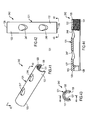
- Housing 536 can have a proximal or upper end 541 provided with a proximal or upper opening 542 to socket 537 for inserting the fastening element 538 into the socket and distal or lower end 543 provided a distal or lower opening 544 through which a portion of the fastening element 538 can extend for securing to the nail head 406.
- Lower end 543 of the housing 536 is sized and shaped to cooperatively engage with the proximal end and proximal opening of nail head 406.
- the lower opening 544 has a diameter approximating the diameter of the proximal opening 103 of nail head 406.
- Housing 536 can be further provided with a registering element or key 551 which is cooperatively sized and shaped to snuggly seat within a recess or notch 552 provided on the proximal end of the nail head 406 so as to rotatably lock and register the housing 536 and thus targeting device 531 with the nail head 406 and thus nail 402.
- Fastening element 538 can be of any suitable type and in one embodiment is a cylindrical nut 538 having a diameter closely approximating but slightly smaller than the diameter of bore or socket 537 in housing 536.
- Nut can be provided with a through hole 556 extending therethrough.
- a suitable drive socket 557 can be provided at the proximal end of the hole 556 for receiving any suitable drive element (not shown) for rotating the nut within housing 536.
- the exterior of the distal end 558 of nut 538 necks down to a smaller diameter at annular surface 559 and is provided with external threads 561 for cooperatively engaging and threading with internal threads 104 at the proximal end of nail head 406.
- Housing 536 is provided with an annular seat or surface 562 in socket 537 for receiving and engaging the annular surface 559 of the nut 538.
- the distal end 558 of nut 538 has a suitable actuation element of any suitable type such as a cylindrical extension 566 which protrudes distally from such end 558.
- the extension 566 can have an external diameter less than the internal diameter of nut 486 of the locking mechanism 439 so as to engage flange 512 of driver 511 of the locking mechanism and simultaneously move the driver 511 distally from its first or locked position, illustrated in FIG. 82 , to its second or unlocked position, illustrated in FIG. 83 , as the nut 538 of the targeting device 531 is screwed into the proximal end of the nail head 406.
- the mere coupling or connecting of the targeting device 531 to the nail unlocks the locking mechanism 439 of the nail and permits the angle of the transverse aperture 416 of the nail, and thus fastener or screw 63, to be adjusted relative to the central axis 404 of the nail.
- pivoting of the fastener 63 is caused by inserting a suitable drive element through nut 538 and housing 536 of the connector 534 into drive socket 513 of driver 511.
- the locking mechanism 439 Prior to such connecting of the targeting assembly 531 to the nail 402 or other implantable device, the locking mechanism 439 is in its locked position so as to preclude angular adjustment of transverse aperture 416 or any fastener 63 therein..
Landscapes
- Health & Medical Sciences (AREA)
- Orthopedic Medicine & Surgery (AREA)
- Surgery (AREA)
- Life Sciences & Earth Sciences (AREA)
- Heart & Thoracic Surgery (AREA)
- Nuclear Medicine, Radiotherapy & Molecular Imaging (AREA)
- Engineering & Computer Science (AREA)
- Biomedical Technology (AREA)
- Neurology (AREA)
- Medical Informatics (AREA)
- Molecular Biology (AREA)
- Animal Behavior & Ethology (AREA)
- General Health & Medical Sciences (AREA)
- Public Health (AREA)
- Veterinary Medicine (AREA)
- Surgical Instruments (AREA)
Applications Claiming Priority (3)
| Application Number | Priority Date | Filing Date | Title |
|---|---|---|---|
| US201161576280P | 2011-12-15 | 2011-12-15 | |
| US13/716,079 US9220544B2 (en) | 2011-12-15 | 2012-12-14 | Implantable device with locking adjustment mechanism and method for using same |
| PCT/US2012/069958 WO2013090859A1 (en) | 2011-12-15 | 2012-12-15 | Implantable device with locking adjustment mechanism and method for using same |
Publications (2)
| Publication Number | Publication Date |
|---|---|
| EP2790601A1 EP2790601A1 (en) | 2014-10-22 |
| EP2790601B1 true EP2790601B1 (en) | 2015-12-09 |
Family
ID=47505345
Family Applications (1)
| Application Number | Title | Priority Date | Filing Date |
|---|---|---|---|
| EP12810498.1A Active EP2790601B1 (en) | 2011-12-15 | 2012-12-15 | Implantable device with locking adjustment mechanism |
Country Status (4)
| Country | Link |
|---|---|
| US (1) | US9220544B2 (enExample) |
| EP (1) | EP2790601B1 (enExample) |
| JP (1) | JP6122442B2 (enExample) |
| WO (1) | WO2013090859A1 (enExample) |
Cited By (1)
| Publication number | Priority date | Publication date | Assignee | Title |
|---|---|---|---|---|
| AT527159A1 (de) * | 2023-04-21 | 2024-11-15 | I T S Gmbh | Flexible Vorrichtung zur Versorgung einer Knochenfraktur |
Families Citing this family (20)
| Publication number | Priority date | Publication date | Assignee | Title |
|---|---|---|---|---|
| EP2672909B1 (en) | 2011-02-08 | 2015-10-21 | Stryker Trauma GmbH | Implant system for bone fixation |
| WO2013151501A1 (en) * | 2012-04-04 | 2013-10-10 | Kok Sun Khong | Surgical implant device, method and apparatus for implanting thereof |
| ES2548045T3 (es) | 2012-10-01 | 2015-10-13 | Stryker Trauma Gmbh | Clavo intramedular y sistema de implante que comprende dicho clavo |
| US10123828B2 (en) * | 2013-03-15 | 2018-11-13 | Epix Orthopaedics, Inc. | Implantable device with pivotable fastener and self-adjusting set screw |
| US9517094B1 (en) * | 2014-05-09 | 2016-12-13 | Savage Medical Design LLC | Intramedullary fixation apparatus for use in hip and femur fracture surgery |
| JP6483847B2 (ja) * | 2014-11-25 | 2019-03-13 | スウェマック・イノヴェーション・アーベー | 髄内釘 |
| US20220151664A1 (en) * | 2015-04-16 | 2022-05-19 | Texas Tech University System | Ankle (Tibio-Talar) Fusion Nail |
| EP3297555B1 (en) | 2015-05-22 | 2019-06-26 | Stryker European Holdings I, LLC | Implant system for bone fixation |
| US9895177B2 (en) * | 2016-01-15 | 2018-02-20 | ARTHREX, GmbH | Bone fixation device for treatment of femoral fractures |
| WO2018042595A1 (ja) * | 2016-09-01 | 2018-03-08 | 株式会社オーミック | 大腿骨固定器具 |
| US10716682B2 (en) | 2017-07-19 | 2020-07-21 | Acumed Llc | Orthopedic alignment guide |
| US11446072B2 (en) | 2017-10-10 | 2022-09-20 | DePuy Synthes Products, Inc. | Self-retaining nail to insertion handle interface |
| AU2019202538B2 (en) * | 2018-04-13 | 2024-02-29 | Stryker European Operations Holdings Llc | Femoral nail with enhanced bone conforming geometry |
| US11266448B2 (en) | 2018-08-09 | 2022-03-08 | Cidaris Ortho, Inc. | Locking intramedullary nail system |
| US12484915B2 (en) | 2018-10-15 | 2025-12-02 | University Of Kentucky Research Foundation | Antegrade retrograde recon femoral intramedullary nail system |
| WO2021176274A1 (en) | 2020-03-06 | 2021-09-10 | Stryker European Operations Limited | Set screw for femoral nail |
| WO2021176272A1 (en) | 2020-03-06 | 2021-09-10 | Stryker European Operations Limited | Set screw for femoral nail |
| TR202008814A2 (tr) * | 2020-06-08 | 2021-03-22 | Acibadem Mehmet Ali Aydinlar Ueniversitesi | Ortopedi̇k bi̇r i̇mplant |
| US12004785B2 (en) | 2022-04-21 | 2024-06-11 | DePuy Synthes Products, Inc. | Retrograde femoral intramedullary nail, and related systems and methods |
| AT528347A1 (de) * | 2024-06-03 | 2025-12-15 | I T S Gmbh | Vorrichtung zur Versorgung einer Knochenfraktur mit Dynamisierungskontrolle |
Family Cites Families (14)
| Publication number | Priority date | Publication date | Assignee | Title |
|---|---|---|---|---|
| US5190544A (en) * | 1986-06-23 | 1993-03-02 | Pfizer Hospital Products Group, Inc. | Modular femoral fixation system |
| JPH024449U (enExample) * | 1988-06-22 | 1990-01-11 | ||
| JP3066920U (ja) * | 1999-08-26 | 2000-03-07 | 定國 周 | ひじかけ用接手 |
| JP2002054657A (ja) * | 2000-08-11 | 2002-02-20 | Shimadzu Corp | 電磁クラッチ |
| JP4071766B2 (ja) * | 2003-12-25 | 2008-04-02 | 株式会社ホムズ技研 | 髄内釘 |
| JP2005248583A (ja) * | 2004-03-04 | 2005-09-15 | Mitsuba Corp | 車両用自動開閉装置 |
| EP1727484A2 (en) | 2004-03-26 | 2006-12-06 | Smith and Nephew, Inc. | Methods for treating fractures of the femur and femoral fracture devices |
| US20070233101A1 (en) * | 2006-03-31 | 2007-10-04 | Metzinger Anthony J | Variable angle intramedullary nail, assembly and method |
| US20070233102A1 (en) | 2006-03-31 | 2007-10-04 | Metzinger Anthony J | Variable angle fixture, kit and method of presetting a nail assembly |
| JP4880407B2 (ja) * | 2006-09-15 | 2012-02-22 | 日本メディカルマテリアル株式会社 | 大腿骨近位部骨折用固定器具 |
| CN101754723B (zh) * | 2007-06-22 | 2012-07-18 | 圣歌整形外科梵有限责任公司 | 带有能够枢转的紧固件的髓内杆 |
| DE102008013699A1 (de) | 2008-03-11 | 2009-09-17 | Schreiber, Hans, Dr. Dr. | Justierbarer Gamma-Nagel |
| JP2010000104A (ja) * | 2008-06-18 | 2010-01-07 | Tetsuo Nakano | 髄内釘及び髄内釘本体 |
| JP5511486B2 (ja) * | 2010-04-26 | 2014-06-04 | 康雄 藍原 | 水頭症治療用シャントバルブ |
-
2012
- 2012-12-14 US US13/716,079 patent/US9220544B2/en active Active
- 2012-12-15 JP JP2014547536A patent/JP6122442B2/ja not_active Expired - Fee Related
- 2012-12-15 EP EP12810498.1A patent/EP2790601B1/en active Active
- 2012-12-15 WO PCT/US2012/069958 patent/WO2013090859A1/en not_active Ceased
Cited By (1)
| Publication number | Priority date | Publication date | Assignee | Title |
|---|---|---|---|---|
| AT527159A1 (de) * | 2023-04-21 | 2024-11-15 | I T S Gmbh | Flexible Vorrichtung zur Versorgung einer Knochenfraktur |
Also Published As
| Publication number | Publication date |
|---|---|
| EP2790601A1 (en) | 2014-10-22 |
| WO2013090859A1 (en) | 2013-06-20 |
| US20140012259A1 (en) | 2014-01-09 |
| US9220544B2 (en) | 2015-12-29 |
| JP6122442B2 (ja) | 2017-04-26 |
| JP2015507487A (ja) | 2015-03-12 |
Similar Documents
| Publication | Publication Date | Title |
|---|---|---|
| EP2790601B1 (en) | Implantable device with locking adjustment mechanism | |
| US10123828B2 (en) | Implantable device with pivotable fastener and self-adjusting set screw | |
| EP3153119B1 (en) | Intramedullary rod with mechanism actuatable at proximal end for pivoting fastener | |
| US8790343B2 (en) | Intramedullary rod with pivotable and fixed fasteners and method for using same | |
| US5122133A (en) | Compression screw for a joint endoprosthesis | |
| EP2782511B1 (en) | Implant system for bone fixation | |
| US20120078306A1 (en) | Bone fixation systems and methods | |
| JP2015507972A (ja) | 連続調節可能ターゲッティングアセンブリを有するインプラント挿入デバイス | |
| US11202663B2 (en) | Proximal humeral stabilization systems and methods thereof | |
| US12458418B2 (en) | Retrograde femoral intramedullary nail, and related systems and methods |
Legal Events
| Date | Code | Title | Description |
|---|---|---|---|
| PUAI | Public reference made under article 153(3) epc to a published international application that has entered the european phase |
Free format text: ORIGINAL CODE: 0009012 |
|
| 17P | Request for examination filed |
Effective date: 20140616 |
|
| AK | Designated contracting states |
Kind code of ref document: A1 Designated state(s): AL AT BE BG CH CY CZ DE DK EE ES FI FR GB GR HR HU IE IS IT LI LT LU LV MC MK MT NL NO PL PT RO RS SE SI SK SM TR |
|
| RAP1 | Party data changed (applicant data changed or rights of an application transferred) |
Owner name: EPIX ORTHOPAEDICS, INC. |
|
| DAX | Request for extension of the european patent (deleted) | ||
| REG | Reference to a national code |
Ref country code: DE Ref legal event code: R079 Ref document number: 602012013006 Country of ref document: DE Free format text: PREVIOUS MAIN CLASS: A61B0017740000 Ipc: A61B0017720000 |
|
| GRAP | Despatch of communication of intention to grant a patent |
Free format text: ORIGINAL CODE: EPIDOSNIGR1 |
|
| RIC1 | Information provided on ipc code assigned before grant |
Ipc: A61B 17/72 20060101AFI20150515BHEP Ipc: A61B 17/74 20060101ALI20150515BHEP |
|
| INTG | Intention to grant announced |
Effective date: 20150623 |
|
| GRAS | Grant fee paid |
Free format text: ORIGINAL CODE: EPIDOSNIGR3 |
|
| GRAA | (expected) grant |
Free format text: ORIGINAL CODE: 0009210 |
|
| AK | Designated contracting states |
Kind code of ref document: B1 Designated state(s): AL AT BE BG CH CY CZ DE DK EE ES FI FR GB GR HR HU IE IS IT LI LT LU LV MC MK MT NL NO PL PT RO RS SE SI SK SM TR |
|
| REG | Reference to a national code |
Ref country code: GB Ref legal event code: FG4D |
|
| REG | Reference to a national code |
Ref country code: AT Ref legal event code: REF Ref document number: 764195 Country of ref document: AT Kind code of ref document: T Effective date: 20151215 Ref country code: CH Ref legal event code: EP Ref country code: CH Ref legal event code: NV Representative=s name: KIRKER AND CIE S.A., CH |
|
| REG | Reference to a national code |
Ref country code: IE Ref legal event code: FG4D |
|
| REG | Reference to a national code |
Ref country code: DE Ref legal event code: R096 Ref document number: 602012013006 Country of ref document: DE |
|
| REG | Reference to a national code |
Ref country code: LT Ref legal event code: MG4D |
|
| REG | Reference to a national code |
Ref country code: FR Ref legal event code: PLFP Year of fee payment: 4 |
|
| REG | Reference to a national code |
Ref country code: NL Ref legal event code: MP Effective date: 20151209 |
|
| PG25 | Lapsed in a contracting state [announced via postgrant information from national office to epo] |
Ref country code: NO Free format text: LAPSE BECAUSE OF FAILURE TO SUBMIT A TRANSLATION OF THE DESCRIPTION OR TO PAY THE FEE WITHIN THE PRESCRIBED TIME-LIMIT Effective date: 20160309 Ref country code: ES Free format text: LAPSE BECAUSE OF FAILURE TO SUBMIT A TRANSLATION OF THE DESCRIPTION OR TO PAY THE FEE WITHIN THE PRESCRIBED TIME-LIMIT Effective date: 20151209 Ref country code: LT Free format text: LAPSE BECAUSE OF FAILURE TO SUBMIT A TRANSLATION OF THE DESCRIPTION OR TO PAY THE FEE WITHIN THE PRESCRIBED TIME-LIMIT Effective date: 20151209 |
|
| REG | Reference to a national code |
Ref country code: AT Ref legal event code: MK05 Ref document number: 764195 Country of ref document: AT Kind code of ref document: T Effective date: 20151209 |
|
| PG25 | Lapsed in a contracting state [announced via postgrant information from national office to epo] |
Ref country code: BE Free format text: LAPSE BECAUSE OF NON-PAYMENT OF DUE FEES Effective date: 20151231 Ref country code: NL Free format text: LAPSE BECAUSE OF FAILURE TO SUBMIT A TRANSLATION OF THE DESCRIPTION OR TO PAY THE FEE WITHIN THE PRESCRIBED TIME-LIMIT Effective date: 20151209 Ref country code: SE Free format text: LAPSE BECAUSE OF FAILURE TO SUBMIT A TRANSLATION OF THE DESCRIPTION OR TO PAY THE FEE WITHIN THE PRESCRIBED TIME-LIMIT Effective date: 20151209 Ref country code: LV Free format text: LAPSE BECAUSE OF FAILURE TO SUBMIT A TRANSLATION OF THE DESCRIPTION OR TO PAY THE FEE WITHIN THE PRESCRIBED TIME-LIMIT Effective date: 20151209 Ref country code: FI Free format text: LAPSE BECAUSE OF FAILURE TO SUBMIT A TRANSLATION OF THE DESCRIPTION OR TO PAY THE FEE WITHIN THE PRESCRIBED TIME-LIMIT Effective date: 20151209 Ref country code: GR Free format text: LAPSE BECAUSE OF FAILURE TO SUBMIT A TRANSLATION OF THE DESCRIPTION OR TO PAY THE FEE WITHIN THE PRESCRIBED TIME-LIMIT Effective date: 20160310 Ref country code: RS Free format text: LAPSE BECAUSE OF FAILURE TO SUBMIT A TRANSLATION OF THE DESCRIPTION OR TO PAY THE FEE WITHIN THE PRESCRIBED TIME-LIMIT Effective date: 20151209 |
|
| PG25 | Lapsed in a contracting state [announced via postgrant information from national office to epo] |
Ref country code: IS Free format text: LAPSE BECAUSE OF FAILURE TO SUBMIT A TRANSLATION OF THE DESCRIPTION OR TO PAY THE FEE WITHIN THE PRESCRIBED TIME-LIMIT Effective date: 20151209 |
|
| PG25 | Lapsed in a contracting state [announced via postgrant information from national office to epo] |
Ref country code: CZ Free format text: LAPSE BECAUSE OF FAILURE TO SUBMIT A TRANSLATION OF THE DESCRIPTION OR TO PAY THE FEE WITHIN THE PRESCRIBED TIME-LIMIT Effective date: 20151209 Ref country code: IT Free format text: LAPSE BECAUSE OF FAILURE TO SUBMIT A TRANSLATION OF THE DESCRIPTION OR TO PAY THE FEE WITHIN THE PRESCRIBED TIME-LIMIT Effective date: 20151209 |
|
| PG25 | Lapsed in a contracting state [announced via postgrant information from national office to epo] |
Ref country code: SK Free format text: LAPSE BECAUSE OF FAILURE TO SUBMIT A TRANSLATION OF THE DESCRIPTION OR TO PAY THE FEE WITHIN THE PRESCRIBED TIME-LIMIT Effective date: 20151209 Ref country code: IS Free format text: LAPSE BECAUSE OF FAILURE TO SUBMIT A TRANSLATION OF THE DESCRIPTION OR TO PAY THE FEE WITHIN THE PRESCRIBED TIME-LIMIT Effective date: 20160409 Ref country code: PT Free format text: LAPSE BECAUSE OF FAILURE TO SUBMIT A TRANSLATION OF THE DESCRIPTION OR TO PAY THE FEE WITHIN THE PRESCRIBED TIME-LIMIT Effective date: 20160411 Ref country code: AT Free format text: LAPSE BECAUSE OF FAILURE TO SUBMIT A TRANSLATION OF THE DESCRIPTION OR TO PAY THE FEE WITHIN THE PRESCRIBED TIME-LIMIT Effective date: 20151209 Ref country code: EE Free format text: LAPSE BECAUSE OF FAILURE TO SUBMIT A TRANSLATION OF THE DESCRIPTION OR TO PAY THE FEE WITHIN THE PRESCRIBED TIME-LIMIT Effective date: 20151209 Ref country code: RO Free format text: LAPSE BECAUSE OF FAILURE TO SUBMIT A TRANSLATION OF THE DESCRIPTION OR TO PAY THE FEE WITHIN THE PRESCRIBED TIME-LIMIT Effective date: 20151209 Ref country code: SM Free format text: LAPSE BECAUSE OF FAILURE TO SUBMIT A TRANSLATION OF THE DESCRIPTION OR TO PAY THE FEE WITHIN THE PRESCRIBED TIME-LIMIT Effective date: 20151209 |
|
| REG | Reference to a national code |
Ref country code: DE Ref legal event code: R097 Ref document number: 602012013006 Country of ref document: DE |
|
| REG | Reference to a national code |
Ref country code: IE Ref legal event code: MM4A |
|
| PG25 | Lapsed in a contracting state [announced via postgrant information from national office to epo] |
Ref country code: MC Free format text: LAPSE BECAUSE OF FAILURE TO SUBMIT A TRANSLATION OF THE DESCRIPTION OR TO PAY THE FEE WITHIN THE PRESCRIBED TIME-LIMIT Effective date: 20151209 |
|
| PLBE | No opposition filed within time limit |
Free format text: ORIGINAL CODE: 0009261 |
|
| STAA | Information on the status of an ep patent application or granted ep patent |
Free format text: STATUS: NO OPPOSITION FILED WITHIN TIME LIMIT |
|
| PG25 | Lapsed in a contracting state [announced via postgrant information from national office to epo] |
Ref country code: DK Free format text: LAPSE BECAUSE OF FAILURE TO SUBMIT A TRANSLATION OF THE DESCRIPTION OR TO PAY THE FEE WITHIN THE PRESCRIBED TIME-LIMIT Effective date: 20151209 Ref country code: PL Free format text: LAPSE BECAUSE OF FAILURE TO SUBMIT A TRANSLATION OF THE DESCRIPTION OR TO PAY THE FEE WITHIN THE PRESCRIBED TIME-LIMIT Effective date: 20151209 Ref country code: IE Free format text: LAPSE BECAUSE OF NON-PAYMENT OF DUE FEES Effective date: 20151215 |
|
| REG | Reference to a national code |
Ref country code: FR Ref legal event code: PLFP Year of fee payment: 5 |
|
| 26N | No opposition filed |
Effective date: 20160912 |
|
| PG25 | Lapsed in a contracting state [announced via postgrant information from national office to epo] |
Ref country code: SI Free format text: LAPSE BECAUSE OF FAILURE TO SUBMIT A TRANSLATION OF THE DESCRIPTION OR TO PAY THE FEE WITHIN THE PRESCRIBED TIME-LIMIT Effective date: 20151209 |
|
| PG25 | Lapsed in a contracting state [announced via postgrant information from national office to epo] |
Ref country code: BE Free format text: LAPSE BECAUSE OF FAILURE TO SUBMIT A TRANSLATION OF THE DESCRIPTION OR TO PAY THE FEE WITHIN THE PRESCRIBED TIME-LIMIT Effective date: 20151209 |
|
| PG25 | Lapsed in a contracting state [announced via postgrant information from national office to epo] |
Ref country code: BG Free format text: LAPSE BECAUSE OF FAILURE TO SUBMIT A TRANSLATION OF THE DESCRIPTION OR TO PAY THE FEE WITHIN THE PRESCRIBED TIME-LIMIT Effective date: 20151209 |
|
| PG25 | Lapsed in a contracting state [announced via postgrant information from national office to epo] |
Ref country code: HU Free format text: LAPSE BECAUSE OF FAILURE TO SUBMIT A TRANSLATION OF THE DESCRIPTION OR TO PAY THE FEE WITHIN THE PRESCRIBED TIME-LIMIT; INVALID AB INITIO Effective date: 20121215 Ref country code: CY Free format text: LAPSE BECAUSE OF FAILURE TO SUBMIT A TRANSLATION OF THE DESCRIPTION OR TO PAY THE FEE WITHIN THE PRESCRIBED TIME-LIMIT Effective date: 20151209 |
|
| PG25 | Lapsed in a contracting state [announced via postgrant information from national office to epo] |
Ref country code: HR Free format text: LAPSE BECAUSE OF FAILURE TO SUBMIT A TRANSLATION OF THE DESCRIPTION OR TO PAY THE FEE WITHIN THE PRESCRIBED TIME-LIMIT Effective date: 20151209 |
|
| PG25 | Lapsed in a contracting state [announced via postgrant information from national office to epo] |
Ref country code: MT Free format text: LAPSE BECAUSE OF FAILURE TO SUBMIT A TRANSLATION OF THE DESCRIPTION OR TO PAY THE FEE WITHIN THE PRESCRIBED TIME-LIMIT Effective date: 20151209 |
|
| REG | Reference to a national code |
Ref country code: FR Ref legal event code: PLFP Year of fee payment: 6 |
|
| PG25 | Lapsed in a contracting state [announced via postgrant information from national office to epo] |
Ref country code: LU Free format text: LAPSE BECAUSE OF NON-PAYMENT OF DUE FEES Effective date: 20151215 |
|
| PG25 | Lapsed in a contracting state [announced via postgrant information from national office to epo] |
Ref country code: MK Free format text: LAPSE BECAUSE OF FAILURE TO SUBMIT A TRANSLATION OF THE DESCRIPTION OR TO PAY THE FEE WITHIN THE PRESCRIBED TIME-LIMIT Effective date: 20151209 |
|
| PG25 | Lapsed in a contracting state [announced via postgrant information from national office to epo] |
Ref country code: AL Free format text: LAPSE BECAUSE OF FAILURE TO SUBMIT A TRANSLATION OF THE DESCRIPTION OR TO PAY THE FEE WITHIN THE PRESCRIBED TIME-LIMIT Effective date: 20151209 Ref country code: TR Free format text: LAPSE BECAUSE OF FAILURE TO SUBMIT A TRANSLATION OF THE DESCRIPTION OR TO PAY THE FEE WITHIN THE PRESCRIBED TIME-LIMIT Effective date: 20151209 |
|
| PGFP | Annual fee paid to national office [announced via postgrant information from national office to epo] |
Ref country code: GB Payment date: 20231026 Year of fee payment: 12 |
|
| PGFP | Annual fee paid to national office [announced via postgrant information from national office to epo] |
Ref country code: FR Payment date: 20231009 Year of fee payment: 12 Ref country code: DE Payment date: 20231017 Year of fee payment: 12 |
|
| PGFP | Annual fee paid to national office [announced via postgrant information from national office to epo] |
Ref country code: CH Payment date: 20240101 Year of fee payment: 12 |
|
| REG | Reference to a national code |
Ref country code: DE Ref legal event code: R119 Ref document number: 602012013006 Country of ref document: DE |
|
| REG | Reference to a national code |
Ref country code: CH Ref legal event code: PL |
|
| GBPC | Gb: european patent ceased through non-payment of renewal fee |
Effective date: 20241215 |
|
| PG25 | Lapsed in a contracting state [announced via postgrant information from national office to epo] |
Ref country code: DE Free format text: LAPSE BECAUSE OF NON-PAYMENT OF DUE FEES Effective date: 20250701 |
|
| PG25 | Lapsed in a contracting state [announced via postgrant information from national office to epo] |
Ref country code: GB Free format text: LAPSE BECAUSE OF NON-PAYMENT OF DUE FEES Effective date: 20241215 |
|
| PG25 | Lapsed in a contracting state [announced via postgrant information from national office to epo] |
Ref country code: FR Free format text: LAPSE BECAUSE OF NON-PAYMENT OF DUE FEES Effective date: 20241231 |
|
| PG25 | Lapsed in a contracting state [announced via postgrant information from national office to epo] |
Ref country code: CH Free format text: LAPSE BECAUSE OF NON-PAYMENT OF DUE FEES Effective date: 20241231 |