EP2789395B2 - Centrifugeuse à vis a bol plein dotée d'un dispositif de récupération d'énergie - Google Patents
Centrifugeuse à vis a bol plein dotée d'un dispositif de récupération d'énergie Download PDFInfo
- Publication number
- EP2789395B2 EP2789395B2 EP13162746.5A EP13162746A EP2789395B2 EP 2789395 B2 EP2789395 B2 EP 2789395B2 EP 13162746 A EP13162746 A EP 13162746A EP 2789395 B2 EP2789395 B2 EP 2789395B2
- Authority
- EP
- European Patent Office
- Prior art keywords
- clarified
- discharge pipe
- designed
- recovery device
- solid bowl
- Prior art date
- Legal status (The legal status is an assumption and is not a legal conclusion. Google has not performed a legal analysis and makes no representation as to the accuracy of the status listed.)
- Active
Links
Images


Classifications
-
- B—PERFORMING OPERATIONS; TRANSPORTING
- B04—CENTRIFUGAL APPARATUS OR MACHINES FOR CARRYING-OUT PHYSICAL OR CHEMICAL PROCESSES
- B04B—CENTRIFUGES
- B04B1/00—Centrifuges with rotary bowls provided with solid jackets for separating predominantly liquid mixtures with or without solid particles
- B04B1/20—Centrifuges with rotary bowls provided with solid jackets for separating predominantly liquid mixtures with or without solid particles discharging solid particles from the bowl by a conveying screw coaxial with the bowl axis and rotating relatively to the bowl
- B04B2001/2075—Centrifuges with rotary bowls provided with solid jackets for separating predominantly liquid mixtures with or without solid particles discharging solid particles from the bowl by a conveying screw coaxial with the bowl axis and rotating relatively to the bowl with means for recovering the energy of the outflowing liquid
-
- B—PERFORMING OPERATIONS; TRANSPORTING
- B04—CENTRIFUGAL APPARATUS OR MACHINES FOR CARRYING-OUT PHYSICAL OR CHEMICAL PROCESSES
- B04B—CENTRIFUGES
- B04B1/00—Centrifuges with rotary bowls provided with solid jackets for separating predominantly liquid mixtures with or without solid particles
- B04B1/20—Centrifuges with rotary bowls provided with solid jackets for separating predominantly liquid mixtures with or without solid particles discharging solid particles from the bowl by a conveying screw coaxial with the bowl axis and rotating relatively to the bowl
- B04B2001/2083—Configuration of liquid outlets
Definitions
- the invention relates to a solid bowl screw centrifuge with a rotatable in operation about a longitudinal axis of the centrifuge drum, at least one outflow opening for discharging clarified Good from the centrifuge drum is formed, which is provided with a discharge opening radially outwardly limiting weir edge, and an energy recovery device is designed to recover energy of the effluent, clarified good. Furthermore, the invention also relates to such an energy recovery device for attachment to a front side of a centrifuge drum.
- the invention has for its object to provide a Vollmantelschneckenzentrifuge whose energy recovery device is particularly effective.
- the outflow opening in the end face of the centrifuge drum extends essentially transversely to the longitudinal axis of the centrifuge.
- the weir edge which can be at least slightly advantageous aligned obliquely to the longitudinal axis.
- the energy recovery device according to the invention which is designed as a over its entire circumference substantially closed tube.
- the pipe of this type thus forms axially outside the discharge opening a discharge line which is closed over its entire circumference.
- This outflow tube acts with respect to the longitudinal axis radially outward like an outflow channel or a discharge channel and is at the same time closed radially in relation to the longitudinal axis.
- the solution according to the invention is based on the recognition that the energy-recovering effect of energy recovery devices of the type mentioned is based, in particular, on the fact that this energy recovery device is closed on its radially inner side.
- this energy recovery device is closed on its radially inner side.
- the flowing through the energy recovery device Good is protected within this against external, aerodynamic influences.
- the local air acts considerably on the outflowing Good, whereby this loses part of its energy content by friction with this air.
- this energy loss is avoided, so that more Energy can be recovered from the effluent.
- the outflowing material in contrast to previously known solutions, can be deflected in a particularly homogeneous and targeted manner from the axial direction substantially in the tangential direction. At the same time energy losses, which would result from a derivative of the outflowing material in the radial direction can be avoided.
- the discharge pipe arranged according to the invention axially outside the outflow opening, the outflowing material during deflection is largely kept at the radius of the associated weir edge, wherein, as explained below, even smaller changes in the radius of the flow path can be advantageous.
- the centrifuge drum can be advantageously configured to be rotatable in two mutually opposite directions of rotation.
- the outflowing, clarified material is preferably deflected counter to a respective direction of rotation of the centrifuge drum with the outflow pipe.
- the energy recovery device according to the invention can also be designed with two active surfaces as outflow tubes, of which the one active surface in a first direction of rotation and the second direction of rotation in the second direction unfolds effect.
- an outflow tube is designed at least with a section with a substantially straight flow path which is inclined at an angle of between 45 ° and 85 °, preferably between 55 ° and 65 °, of the longitudinal axis of the centrifuge drum.
- An outflow tube according to a further embodiment of the invention, at least one section has a substantially straight flow path, which is inclined to the tangential direction at the outflow opening by an angle of 4 ° to 28 °, preferably 8 °, radially inwardly.
- the bottom surface of such a section is particularly advantageous at least partially flat or largely designed flat. Such a bottom surface can be manufactured inexpensively.
- the material flowing therefrom over a longer distance undergoes a uniform and thus comparatively easy model-technically comprehensible acceleration.
- the acceleration leads to an increased conversion of the centrifugal force pulse into a tangentially directed motion pulse. It is considered a particularly large proportion of centrifugal energy in tangential drive energy changed.
- the flat portion of the bottom surface is particularly preferably inclined to the tangential direction by an angle of 4 ° to 28 °, preferably 8 ° radially inwardly.
- Such an orientation of the deflected Gutstrahls leads in comparison to a purely tangential flow to a predefined predetermined deceleration of the exiting stream and thus to a precisely predetermined stowage effect. This jamming brings an increase in the potential energy of the flowing material and thus an improved subsequent conversion into tangential kinetic energy with it.
- an outflow pipe has a discharge opening with a flow path or flow direction, which is inclined at an angle between 70 ° and 90 °, preferably between 77 ° and 83 °, with respect to the longitudinal axis of the centrifuge drum.
- the outflowing material is deflected from initially axially to substantially tangentially, ie transversely thereto.
- a deflection to less than 90 ° with respect to the longitudinal axis has the advantage that the emerging from the Abstrommündung Good is less strongly directed against the end face of the centrifuge drum and therefore there occur less friction losses.
- the solution according to the invention also advantageously provides a solid shell screw centrifuge, in which the outflow pipe is designed in the flow direction of the discharged, clarified material with a constant large flow cross section.
- the outflow pipe is designed in the flow direction of the outflowing, clarified material with decreasing, in particular conically tapered, flow cross section.
- the non-tapered flow shape reduces the risk of clogging of the discharge tube during operation of the associated solid bowl centrifuge.
- the tapered tube shape creates an additional stowage effect resulting in improved energy recovery.
- the outflow pipe is further designed with a round, in particular circular or elliptical cross section.
- the discharge pipe is designed with a rectangular, in particular square cross-section.
- the two mentioned cross-sectional shapes lead to particularly cost-recoverable energy recovery devices.
- these cross sections are special suitable for allowing the effluent to flow off in a predictable manner.
- a rectangular cross-section also has the advantage that the outflowing material exits at the associated Abströmmündung on a wide plane to a predefined radius.
- the outflow pipe is still designed on its outer wall turned in the direction of rotation with an adapted aerodynamic outer wall shape.
- the flow resistance of the energy recovery device and thus the associated energy loss can be reduced.
- aerodynamically adapted outer wall form is understood to mean a shape that offers the lowest possible flow resistance for incoming air. Such a shape is rounded, has no edges and is provided with a smooth, less rough surface.
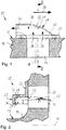
- a solid bowl screw centrifuge 10 whose centrifuge drum 12 with its end face or end wall 14.
- On the end wall 14 one of a plurality of axially, in the direction of a longitudinal axis 18 of the centrifuge drum 12 through the end wall 14 protruding outflow openings 16 is illustrated.
- On the outside in front of the discharge opening 16, a weir plate 20 is stationary, but adjustably mounted on the end wall 14. The weir plate 20 protrudes up to the discharge opening 16 so that it covers the outside at its radially outer region. In this case, the weir plate 20 at its radially inwardly directed edge to a weir edge 22.
- the weir edge 22 extends along the end wall 14 and thus transversely to the longitudinal axis 18.
- the weir edge 22 holds in the centrifuge drum 12 clarified Good 24 back, so that in operation of the solid bowl centrifuge 10 this clarified Good 24 there with a Pond depth 26 accumulates and subsequently flows largely continuously over the weir edge 22 away.
- an energy recovery device 28 In the flow direction of the clarified material 24 behind or downstream of the weir edge 22 is located axially on the outside of the weir plate 20, an energy recovery device 28 according to the prior art.
- This energy recovery device 28 is designed as a discharge channel or a discharge channel 30 which has a flat bottom surface 32 that extends tangentially at the height of the weir edge 22.
- To the bottom surface 32 extends as part of the outflow channel 30 perpendicular to a deflection surface 34, which extends arcuately according to the prior art in front of the viewed in the longitudinal direction open region of the discharge opening 16.
- the deflecting surface 34 deflects the clarified good 24, which flows axially through the discharge opening 16 radially inwards, under the weir edge 22 in an inflow direction 38, in a tangential direction to a discharge direction 40.
- the centrifuge drum 12 rotates in a direction of rotation 36 and the clarified Good 24 is deflected by the deflection surface 34 that it emerges tangentially from the energy recovery device 28 against this direction of rotation 36.
- the clarified Good 24 "pushes" from the centrifuge drum 12, whereby it transmits to this part of its pulse and contributes to an energy recovery at the centrifuge drum 12. This "repulsion" is mitigated by the internal fluid friction in the clarified Good 24 and the fact that the centrifuge drum 12 at the same time continues to rotate in the direction of rotation 36.
- the centrifuge drum 12 thus gives way to the repulsion partially.
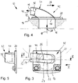
- a solid bowl screw centrifuge 10 illustrated with the centrifuge drum 12, on which an energy recovery device 42 according to the invention is arranged.
- the energy recovery device 42 also has the weir plate 20 of conventional type in front of the associated outflow opening 16.
- On the weir plate 20 is axially outside a discharge pipe 44 which is flowed through by the exiting through the discharge opening 16, outflowing, clarified Good.
- the outflow pipe 44 is located directly in front of the otherwise open region of the outflow opening 16 with respect to its cross section, so that it is completely covered on the outside by the outflow pipe 44. Accordingly, no air flow can act on the passage of the clarified Guts at the outlet opening 16 from the outside, resulting in a particularly uniform, in particular purely laminar flow with appropriate purity of discharged, clarified Guts yields.
- the outlet pipe 44 is located at the height or the radius of the weir edge 20, so that the material flowing through it undergoes virtually no change in position in the radial direction and accordingly no energy losses result.
- the discharge pipe 44 is completely closed and as such forms a tubular conduit with an inlet port 46 in front of the discharge port 16 and a discharge port 48 at its other, outer end.
- the radially outer part of this tube acts in relation to the longitudinal axis like an outflow channel or a discharge channel and is at the same time radially inwardly closed with respect to the longitudinal axis of the centrifuge drum 12.
- the material flowing out through the energy recovery device 42 is also protected inside the outflow pipe 44 against external, aerodynamic influences. The material is deflected homogeneously and without turbulence purposefully from the axial direction or inflow direction 38 substantially in the tangential direction or outflow direction 40.
- the outflow pipe 44 With the outflow pipe 44, the outflowing material during the deflection is largely maintained on the radius of the weir edge 22, wherein the outflow pipe 44 in the side view ( Fig. 3 ) straight flow path 50 which is inclined to the tangential direction 52 at the discharge opening 16 by an angle 54 of 6 ° to 8 ° radially inwardly.
- An associated bottom surface 56 of the outflow pipe 44 is flat or largely designed flat and also at an angle 54 of 6 ° to 8 ° obliquely to the tangential direction 52.
- the outflow pipe 44 according to the Fig. 3 to 5 a rectangular flow cross-section 56, which is starting from the Einströmmündung 46 continuously tapered to Abströmmündung 48. With such a taper, the outflowing material is additionally jammed and bundled into a beam.
- the local outflow pipe 44 is designed with an oval flow cross section 56.
- the flow cross-section 56 of this type likewise tapers over the flow path of the outflowing material through the outflow pipe 44.
- the outflow pipe 44 downstream of the inlet orifice 46 has a section with a longitudinal section ( Fig. 7 ) substantially straight flow path 58, which is inclined to the longitudinal axis 18 of the centrifuge drum at an angle 60 between 55 ° and 65 °.
- this design for the outflow pipe 44 is a teardrop shape (see Fig. 6 ), which is aerodynamically particularly advantageous.
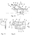
- Fig. 9 to 11 show an embodiment of an energy recovery device 42, in which the outflow pipe 44 is designed with a substantially circular flow cross-section 56.
- the flow path 58 which is essentially straight in longitudinal section, extends over the entire length of the outflow pipe 44, so that it is designed overall as a straight, cylindrical pipe.
- the solution of this kind is very inexpensive to produce.
- an embodiment of an energy recovery device 42 is illustrated, in which the associated outflow pipe 44 is designed in front of the discharge opening 16 as an inclined conical tube.
- the tube is inclined to the longitudinal axis 18 at an angle 60 of 60 °, conically over its entire length and designed to be rectangular in the flow cross-section 56.
- the height of the flow cross-section 56 is kept constant over the length of the outflow pipe 44.
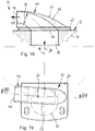
- the in the 15 to 17 illustrated energy recovery device 42 is designed with a kinked outflow pipe 44 having a behind a first portion at an angle 60 to the longitudinal axis 18 of 30 ° a second portion with an angle 64 to the longitudinal axis 18 of 75 °.
- This second section forms a flow direction 62 at the associated exhaust port 48, so that the local flow path or flow direction 62 with respect to the longitudinal axis 18 of the centrifuge drum 12 is also inclined at an angle 64 of 75 °.
- the outflowing material is deflected in principle transversely to the longitudinal axis 18, but at the same time is not deflected so strongly against the end wall 14 that energy losses occur there due to fluid friction during the outflow.
- the local outflow pipe 44 is designed on its outer wall 66 facing in the direction of rotation 36 with an adapted aerodynamic outer wall form 68.
- the outer wall form 68 is such that the wall thickness, starting from the inflow opening 46, decreases steadily in the flow direction of the outflowing material up to the outlet 48.
- the outside of the outer wall 66 is in With respect to the air flowing there when rotating the centrifuge drum 12 flatter and thus designed less in terms of the flow resistance.
- this form of wall thickness is advantageous in view of a high rigidity of the outflow pipe 44 in relation to its weight.
- FIGS. 18 and 19 is this shape design of a discharge pipe 44 with a continuously tapering, inner flow cross-section 56 and a continuous arc shape similar to those in Figs Fig. 3 to 5 combined.
- the embodiment according to the FIGS. 20 and 21 also shows a continuous arc shape of the discharge pipe 44, wherein the flow cross-section 56 is kept the same size over the entire flow length. With such a flow cross-sectional profile, clogging of the outflow pipe 44 with outflowing material is additionally prevented.
Claims (9)
- Centrifugeuse à vis à bol plein (10) dotée d'un tambour de centrifugeuse (12) pouvant tourner en fonctionnement autour d'un axe longitudinal (18), au moins une ouverture d'évacuation (16) étant réalisée au niveau du côté avant (14) dudit tambour pour évacuer le produit décanté (24) hors du tambour de centrifugeuse (12), ladite ouverture étant pourvue d'un bord de débordement (22) délimitant l'ouverture d'évacuation (16) radialement vers l'extérieur et un dispositif de récupération d'énergie (28 ; 42) étant réalisé pour récupérer l'énergie du produit décanté (24) s'évacuant, ledit dispositif étant réalisé sous la forme d'un tube d'évacuation (44) traversé par le produit décanté (24) s'évacuant,
dans laquelle
le dispositif de récupération d'énergie (42) prenant la forme du tube d'évacuation (44) traversé par le produit décanté (24) s'évacuant est disposé à l'extérieur devant l'ouverture d'évacuation (16) comportant le bord de débordement (22),
caractérisée en ce que
le tube d'évacuation (44) comporte au moins une section avec une voie d'écoulement (50) pour l'essentiel droite placée de façon inclinée selon un angle (54) de 4° à 28°, de préférence de 8°, radialement vers l'intérieur par rapport à la direction tangentielle (52) au niveau de l'ouverture d'évacuation (16). - Centrifugeuse à vis à bol plein (10) dotée d'un tambour de centrifugeuse (12) pouvant tourner en fonctionnement autour d'un axe longitudinal (18), au moins une ouverture d'évacuation (16) étant réalisée au niveau du côté avant (14) dudit tambour pour évacuer le produit décanté (24) hors du tambour de centrifugeuse (12), ladite ouverture étant pourvue d'un bord de débordement (22) délimitant l'ouverture d'évacuation (16) radialement vers l'extérieur et un dispositif de récupération d'énergie (28 ; 42) étant réalisé pour récupérer l'énergie du produit décanté (24) s'évacuant, ledit dispositif étant réalisé sous la forme d'un tube d'évacuation (44) traversé par le produit décanté (24) s'évacuant,
dans laquelle
le dispositif de récupération d'énergie (42) prenant la forme du tube d'évacuation (44) traversé par le produit décanté (24) s'évacuant est disposé à l'extérieur devant l'ouverture d'évacuation (16) comportant le bord de débordement (22),
caractérisée en ce que
le tube d'évacuation (44) comporte au moins une section avec une voie d'écoulement (50) pour l'essentiel droite placée de façon inclinée selon un angle (60) compris entre 45° et 85°, de façon préférée entre 55° et 65° par rapport à l'axe longitudinal (18) du tambour de centrifugeuse (12). - Centrifugeuse à vis à bol plein (10) dotée d'un tambour de centrifugeuse (12) pouvant tourner en fonctionnement autour d'un axe longitudinal (18), au moins une ouverture d'évacuation (16) étant réalisée au niveau du côté avant (14) dudit tambour pour évacuer le produit décanté (24) hors du tambour de centrifugeuse (12), ladite ouverture étant pourvue d'un bord de débordement (22) délimitant l'ouverture d'évacuation (16) radialement vers l'extérieur et un dispositif de récupération d'énergie (28 ; 42) étant réalisé pour récupérer l'énergie du produit décanté (24) s'évacuant, ledit dispositif étant réalisé sous la forme d'un tube d'évacuation (44) traversé par le produit décanté (24) s'évacuant,
dans laquelle
le dispositif de récupération d'énergie (42) prenant la forme du tube d'évacuation (44) traversé par le produit décanté (24) s'évacuant est disposé à l'extérieur devant l'ouverture d'évacuation (16) comportant le bord de débordement (22),
caractérisée en ce que
le tube d'évacuation (44) comporte une embouchure d'évacuation (48) avec une direction d'écoulement (62) placée de façon inclinée selon un angle (64) compris entre 70° et 90°, de façon préférée entre 77° et 83°, par rapport à l'axe longitudinal (18) du tambour de centrifugeuse (12). - Centrifugeuse à vis à bol plein selon l'une quelconque des revendications 1 à 3, dans laquelle le produit décanté (24) s'évacuant est renvoyé à l'aide du tube d'évacuation (44) à l'encontre d'une direction de rotation (36) respective du tambour de centrifugeuse (12).
- Centrifugeuse à vis à bol plein selon l'une quelconque des revendications 1 à 4, dans laquelle le tube d'évacuation (44) est conçu avec une section transversale d'écoulement (56) de grandeur constante dans la direction d'écoulement du produit décanté (24) s'évacuant.
- Centrifugeuse à vis à bol plein selon l'une quelconque des revendications 1 à 4, dans laquelle le tube d'évacuation (44) est conçu dans la direction d'écoulement du produit décanté (24) s'évacuant avec une section transversale d'écoulement (56) se réduisant, se rétrécissant notamment de façon conique.
- Centrifugeuse à vis à bol plein selon l'une quelconque des revendications 1 à 6, dans laquelle le tube d'évacuation (44) est conçu avec une section transversale d'écoulement (56) ronde, notamment en forme de cercle ou d'ellipse.
- Centrifugeuse à vis à bol plein selon l'une quelconque des revendications 1 à 6, dans laquelle le tube d'évacuation (44) est conçu avec une section transversale d'écoulement (56) rectangulaire, notamment carrée.
- Centrifugeuse à vis à bol plein selon l'une quelconque des revendications 1 à 8, dans laquelle le tube d'évacuation (44) est conçu au niveau de sa paroi extérieure (66) orientée dans la direction de rotation (36) avec une forme de paroi extérieure (68) à aérodynamisme adapté.
Priority Applications (4)
| Application Number | Priority Date | Filing Date | Title |
|---|---|---|---|
| EP13162746.5A EP2789395B2 (fr) | 2013-04-08 | 2013-04-08 | Centrifugeuse à vis a bol plein dotée d'un dispositif de récupération d'énergie |
| DK13162746.5T DK2789395T4 (da) | 2013-04-08 | 2013-04-08 | Dekantercentrifuge med en energigenvindingsenhed |
| PCT/EP2014/053304 WO2014166664A1 (fr) | 2013-04-08 | 2014-02-20 | Centrifugeuse à vis à bol plein munie d'un dispositif de récupération d'énergie |
| US14/782,603 US10357784B2 (en) | 2013-04-08 | 2014-02-20 | Solid-wall scroll centrifuge with front wall with discharge opening having a weir edge and an energy recovery device defining a discharge pipe on the outside of the front wall and in front of the discharge opening having the weir edge |
Applications Claiming Priority (1)
| Application Number | Priority Date | Filing Date | Title |
|---|---|---|---|
| EP13162746.5A EP2789395B2 (fr) | 2013-04-08 | 2013-04-08 | Centrifugeuse à vis a bol plein dotée d'un dispositif de récupération d'énergie |
Publications (3)
| Publication Number | Publication Date |
|---|---|
| EP2789395A1 EP2789395A1 (fr) | 2014-10-15 |
| EP2789395B1 EP2789395B1 (fr) | 2016-11-02 |
| EP2789395B2 true EP2789395B2 (fr) | 2019-11-06 |
Family
ID=48049866
Family Applications (1)
| Application Number | Title | Priority Date | Filing Date |
|---|---|---|---|
| EP13162746.5A Active EP2789395B2 (fr) | 2013-04-08 | 2013-04-08 | Centrifugeuse à vis a bol plein dotée d'un dispositif de récupération d'énergie |
Country Status (4)
| Country | Link |
|---|---|
| US (1) | US10357784B2 (fr) |
| EP (1) | EP2789395B2 (fr) |
| DK (1) | DK2789395T4 (fr) |
| WO (1) | WO2014166664A1 (fr) |
Families Citing this family (5)
| Publication number | Priority date | Publication date | Assignee | Title |
|---|---|---|---|---|
| DK176946B1 (da) * | 2007-05-09 | 2010-06-14 | Alfa Laval Corp Ab | Centrifugalseparator og et væskefaseafløbsportelement |
| DE102012106226A1 (de) * | 2012-07-11 | 2014-01-16 | Gea Mechanical Equipment Gmbh | Vollmantel-Schneckenzentrifuge mit Überlaufwehr |
| JP5220950B1 (ja) * | 2012-11-02 | 2013-06-26 | 巴工業株式会社 | 分離液噴射ノズル付き遠心分離機 |
| DE102013001436A1 (de) * | 2013-01-29 | 2014-07-31 | Flottweg Se | Vollmantelschneckenzentrifuge mit einer Wehrkante |
| EP2789395B2 (fr) * | 2013-04-08 | 2019-11-06 | Flottweg SE | Centrifugeuse à vis a bol plein dotée d'un dispositif de récupération d'énergie |
Citations (7)
| Publication number | Priority date | Publication date | Assignee | Title |
|---|---|---|---|---|
| DE3112585A1 (de) † | 1981-03-30 | 1982-10-14 | Buckau-Walther AG, 4048 Grevenbroich | Verfahren und vorrichtung zum trennen eines zweistoffgemisches |
| JPH11197547A (ja) † | 1998-01-13 | 1999-07-27 | Kubota Corp | 横型遠心分離機における分離水の排出装置 |
| WO2008138345A1 (fr) † | 2007-05-09 | 2008-11-20 | Alfa Laval Corporate Ab | Séparateur centrifuge et élément formant orifice de décharge en phase liquide |
| WO2012002337A1 (fr) † | 2010-06-29 | 2012-01-05 | 株式会社コベルコ科研 | Poudre, corps fritté et cible de pulvérisation contenant chacun des éléments cu, in, ga et se, et procédé de production de ladite poudre |
| WO2012089492A1 (fr) † | 2010-12-27 | 2012-07-05 | Gea Mechanical Equipment Gmbh | Centrifugeuse à vis sans fin et à bol plein, munie d'un déversoir |
| EP2551021A1 (fr) † | 2011-07-29 | 2013-01-30 | Andritz S.A.S. | Centrifugeuse et élément de port de décharge d'une centrifugeuse pour la réduction de puissance |
| EP2551019A1 (fr) † | 2011-07-29 | 2013-01-30 | Flottweg SE | Centrifugeuse à vis a bol plein dotée d'un bord faisant barrage |
Family Cites Families (12)
| Publication number | Priority date | Publication date | Assignee | Title |
|---|---|---|---|---|
| US4334647A (en) * | 1980-12-03 | 1982-06-15 | Bird Machine Company, Inc. | Centrifuges |
| JP3543597B2 (ja) | 1997-12-22 | 2004-07-14 | 株式会社クボタ | 横型遠心分離機における分離水の排出装置 |
| US20040072668A1 (en) | 2002-10-15 | 2004-04-15 | Baker Hughes Incorporated | Liquid phase discharge port incorporating chamber nozzle device for centrifuge |
| US7022061B2 (en) | 2002-10-15 | 2006-04-04 | Andritz Ag | Centrifuge discharge port with power recovery |
| DK200801846A (en) | 2008-12-30 | 2010-07-01 | Alfa Laval Corp Ab | A decanter centrifuge with a slide valve body |
| DE102010032503A1 (de) | 2010-07-28 | 2012-02-02 | Gea Mechanical Equipment Gmbh | Vollmantel-Schneckenzentrifuge mit Überlaufwehr |
| DK178253B1 (en) | 2010-11-12 | 2015-10-12 | Alfa Laval Corp Ab | A centrifugal separator and an outlet element for a centrifugal separator |
| DE102012014563B4 (de) * | 2012-07-23 | 2014-12-11 | Flottweg Se | Vollmantelschneckenzentrifuge mit einer Energierückgewinnungseinrichtung |
| DE102013001436A1 (de) * | 2013-01-29 | 2014-07-31 | Flottweg Se | Vollmantelschneckenzentrifuge mit einer Wehrkante |
| EP2789395B2 (fr) * | 2013-04-08 | 2019-11-06 | Flottweg SE | Centrifugeuse à vis a bol plein dotée d'un dispositif de récupération d'énergie |
| DE102014101205B4 (de) * | 2014-01-31 | 2021-08-05 | Flottweg Se | Auslassvorrichtung einer Vollmantelschneckenzentrifuge |
| DE102014108722A1 (de) * | 2014-04-30 | 2015-11-05 | Hiller Gmbh | Schneckenzentrifuge |
-
2013
- 2013-04-08 EP EP13162746.5A patent/EP2789395B2/fr active Active
- 2013-04-08 DK DK13162746.5T patent/DK2789395T4/da active
-
2014
- 2014-02-20 WO PCT/EP2014/053304 patent/WO2014166664A1/fr active Application Filing
- 2014-02-20 US US14/782,603 patent/US10357784B2/en active Active
Patent Citations (7)
| Publication number | Priority date | Publication date | Assignee | Title |
|---|---|---|---|---|
| DE3112585A1 (de) † | 1981-03-30 | 1982-10-14 | Buckau-Walther AG, 4048 Grevenbroich | Verfahren und vorrichtung zum trennen eines zweistoffgemisches |
| JPH11197547A (ja) † | 1998-01-13 | 1999-07-27 | Kubota Corp | 横型遠心分離機における分離水の排出装置 |
| WO2008138345A1 (fr) † | 2007-05-09 | 2008-11-20 | Alfa Laval Corporate Ab | Séparateur centrifuge et élément formant orifice de décharge en phase liquide |
| WO2012002337A1 (fr) † | 2010-06-29 | 2012-01-05 | 株式会社コベルコ科研 | Poudre, corps fritté et cible de pulvérisation contenant chacun des éléments cu, in, ga et se, et procédé de production de ladite poudre |
| WO2012089492A1 (fr) † | 2010-12-27 | 2012-07-05 | Gea Mechanical Equipment Gmbh | Centrifugeuse à vis sans fin et à bol plein, munie d'un déversoir |
| EP2551021A1 (fr) † | 2011-07-29 | 2013-01-30 | Andritz S.A.S. | Centrifugeuse et élément de port de décharge d'une centrifugeuse pour la réduction de puissance |
| EP2551019A1 (fr) † | 2011-07-29 | 2013-01-30 | Flottweg SE | Centrifugeuse à vis a bol plein dotée d'un bord faisant barrage |
Also Published As
| Publication number | Publication date |
|---|---|
| US10357784B2 (en) | 2019-07-23 |
| DK2789395T3 (en) | 2017-01-16 |
| WO2014166664A1 (fr) | 2014-10-16 |
| EP2789395B1 (fr) | 2016-11-02 |
| US20160067718A1 (en) | 2016-03-10 |
| DK2789395T4 (da) | 2020-02-10 |
| EP2789395A1 (fr) | 2014-10-15 |
Similar Documents
| Publication | Publication Date | Title |
|---|---|---|
| EP2789395B2 (fr) | Centrifugeuse à vis a bol plein dotée d'un dispositif de récupération d'énergie | |
| EP2950932B1 (fr) | Centrifugeuse à vis à bol plein dotée d'un bord faisant barrage | |
| DE2038045B2 (de) | Zyklon | |
| EP2872256B1 (fr) | Centrifugeuse à vis sans fin et à bol plein avec déversoir de débordement | |
| WO2012013624A2 (fr) | Centrifugeuse à vis sans fin et à bol plein avec déversoir de débordement | |
| DE1301796B (de) | Hydrozyklon | |
| WO2017063830A1 (fr) | Système utilisant l'énergie cinétique, en particulier éolienne | |
| EP2643596B1 (fr) | Pompe auto-nettoyante à rouet centrifuge hélicoïdal avec écoulement auxiliaire de rinçage derrière le rouet | |
| EP0224527A1 (fr) | Dispositif de transformation de l'ecoulement d'un fluide | |
| EP0638365B1 (fr) | Procédé et dispositif pour séparer des matières solides à grains fins en deux fractions granulométriques | |
| EP2923769B1 (fr) | Dispositif d'évacuation et centrifugeuse à vis à bol plein | |
| DE2341789C3 (de) | Anordnung zur Energierückgewinnung im Reingasauslaß eines Drehströmungswirbler« | |
| DE102012014563B4 (de) | Vollmantelschneckenzentrifuge mit einer Energierückgewinnungseinrichtung | |
| DE2556382C3 (de) | Zentrifugalwindsichter | |
| DE102011105409A1 (de) | Venturiwäscher | |
| EP2551019B1 (fr) | Centrifugeuse à vis a bol plein dotée d'un bord faisant barrage | |
| DE2013499A1 (de) | Anordnung für einen Zyklonenabscheider mit einer Entleerungskammer | |
| DE102009038743A1 (de) | Schälscheibe einer Zentrifuge | |
| DE202011110235U1 (de) | Zentrifuge und Auslassanschluss-Bauteil einer Zentrifuge zur Leistungsverringerung | |
| AT523931B1 (de) | Vorrichtung zur fliehkraftbedingten Abscheidung von Partikeln aus einem Gasstrom | |
| AT517463A4 (de) | Leiteinrichtung einer Abscheidevorrichtung | |
| DE2204161C3 (de) | Umluft-Streuwindsichter | |
| DE112013002676T5 (de) | Rotorelement und Rotor für eine Siebvorrichtung | |
| DE1417623C (fr) | ||
| DE1938638U (de) | Zyklonabscheider zum abtrennen von fremdteilen aus druckgasen. |
Legal Events
| Date | Code | Title | Description |
|---|---|---|---|
| PUAI | Public reference made under article 153(3) epc to a published international application that has entered the european phase |
Free format text: ORIGINAL CODE: 0009012 |
|
| 17P | Request for examination filed |
Effective date: 20140328 |
|
| AK | Designated contracting states |
Kind code of ref document: A1 Designated state(s): AL AT BE BG CH CY CZ DE DK EE ES FI FR GB GR HR HU IE IS IT LI LT LU LV MC MK MT NL NO PL PT RO RS SE SI SK SM TR |
|
| AX | Request for extension of the european patent |
Extension state: BA ME |
|
| RBV | Designated contracting states (corrected) |
Designated state(s): AL AT BE BG CH CY CZ DE DK EE ES FI FR GB GR HR HU IE IS IT LI LT LU LV MC MK MT NL NO PL PT RO RS SE SI SK SM TR |
|
| GRAP | Despatch of communication of intention to grant a patent |
Free format text: ORIGINAL CODE: EPIDOSNIGR1 |
|
| INTG | Intention to grant announced |
Effective date: 20160606 |
|
| GRAS | Grant fee paid |
Free format text: ORIGINAL CODE: EPIDOSNIGR3 |
|
| GRAA | (expected) grant |
Free format text: ORIGINAL CODE: 0009210 |
|
| AK | Designated contracting states |
Kind code of ref document: B1 Designated state(s): AL AT BE BG CH CY CZ DE DK EE ES FI FR GB GR HR HU IE IS IT LI LT LU LV MC MK MT NL NO PL PT RO RS SE SI SK SM TR |
|
| REG | Reference to a national code |
Ref country code: GB Ref legal event code: FG4D Free format text: NOT ENGLISH |
|
| REG | Reference to a national code |
Ref country code: AT Ref legal event code: REF Ref document number: 841272 Country of ref document: AT Kind code of ref document: T Effective date: 20161115 Ref country code: CH Ref legal event code: EP |
|
| REG | Reference to a national code |
Ref country code: IE Ref legal event code: FG4D Free format text: LANGUAGE OF EP DOCUMENT: GERMAN |
|
| REG | Reference to a national code |
Ref country code: DE Ref legal event code: R096 Ref document number: 502013005149 Country of ref document: DE |
|
| REG | Reference to a national code |
Ref country code: SE Ref legal event code: TRGR |
|
| REG | Reference to a national code |
Ref country code: DK Ref legal event code: T3 Effective date: 20170112 |
|
| PG25 | Lapsed in a contracting state [announced via postgrant information from national office to epo] |
Ref country code: LV Free format text: LAPSE BECAUSE OF FAILURE TO SUBMIT A TRANSLATION OF THE DESCRIPTION OR TO PAY THE FEE WITHIN THE PRESCRIBED TIME-LIMIT Effective date: 20161102 |
|
| REG | Reference to a national code |
Ref country code: NL Ref legal event code: MP Effective date: 20161102 |
|
| REG | Reference to a national code |
Ref country code: LT Ref legal event code: MG4D |
|
| REG | Reference to a national code |
Ref country code: FR Ref legal event code: PLFP Year of fee payment: 5 |
|
| PG25 | Lapsed in a contracting state [announced via postgrant information from national office to epo] |
Ref country code: GR Free format text: LAPSE BECAUSE OF FAILURE TO SUBMIT A TRANSLATION OF THE DESCRIPTION OR TO PAY THE FEE WITHIN THE PRESCRIBED TIME-LIMIT Effective date: 20170203 Ref country code: NL Free format text: LAPSE BECAUSE OF FAILURE TO SUBMIT A TRANSLATION OF THE DESCRIPTION OR TO PAY THE FEE WITHIN THE PRESCRIBED TIME-LIMIT Effective date: 20161102 Ref country code: LT Free format text: LAPSE BECAUSE OF FAILURE TO SUBMIT A TRANSLATION OF THE DESCRIPTION OR TO PAY THE FEE WITHIN THE PRESCRIBED TIME-LIMIT Effective date: 20161102 Ref country code: NO Free format text: LAPSE BECAUSE OF FAILURE TO SUBMIT A TRANSLATION OF THE DESCRIPTION OR TO PAY THE FEE WITHIN THE PRESCRIBED TIME-LIMIT Effective date: 20170202 |
|
| PG25 | Lapsed in a contracting state [announced via postgrant information from national office to epo] |
Ref country code: PT Free format text: LAPSE BECAUSE OF FAILURE TO SUBMIT A TRANSLATION OF THE DESCRIPTION OR TO PAY THE FEE WITHIN THE PRESCRIBED TIME-LIMIT Effective date: 20170302 Ref country code: FI Free format text: LAPSE BECAUSE OF FAILURE TO SUBMIT A TRANSLATION OF THE DESCRIPTION OR TO PAY THE FEE WITHIN THE PRESCRIBED TIME-LIMIT Effective date: 20161102 Ref country code: HR Free format text: LAPSE BECAUSE OF FAILURE TO SUBMIT A TRANSLATION OF THE DESCRIPTION OR TO PAY THE FEE WITHIN THE PRESCRIBED TIME-LIMIT Effective date: 20161102 Ref country code: IS Free format text: LAPSE BECAUSE OF FAILURE TO SUBMIT A TRANSLATION OF THE DESCRIPTION OR TO PAY THE FEE WITHIN THE PRESCRIBED TIME-LIMIT Effective date: 20170302 Ref country code: RS Free format text: LAPSE BECAUSE OF FAILURE TO SUBMIT A TRANSLATION OF THE DESCRIPTION OR TO PAY THE FEE WITHIN THE PRESCRIBED TIME-LIMIT Effective date: 20161102 Ref country code: ES Free format text: LAPSE BECAUSE OF FAILURE TO SUBMIT A TRANSLATION OF THE DESCRIPTION OR TO PAY THE FEE WITHIN THE PRESCRIBED TIME-LIMIT Effective date: 20161102 Ref country code: PL Free format text: LAPSE BECAUSE OF FAILURE TO SUBMIT A TRANSLATION OF THE DESCRIPTION OR TO PAY THE FEE WITHIN THE PRESCRIBED TIME-LIMIT Effective date: 20161102 |
|
| PG25 | Lapsed in a contracting state [announced via postgrant information from national office to epo] |
Ref country code: RO Free format text: LAPSE BECAUSE OF FAILURE TO SUBMIT A TRANSLATION OF THE DESCRIPTION OR TO PAY THE FEE WITHIN THE PRESCRIBED TIME-LIMIT Effective date: 20161102 Ref country code: SK Free format text: LAPSE BECAUSE OF FAILURE TO SUBMIT A TRANSLATION OF THE DESCRIPTION OR TO PAY THE FEE WITHIN THE PRESCRIBED TIME-LIMIT Effective date: 20161102 Ref country code: EE Free format text: LAPSE BECAUSE OF FAILURE TO SUBMIT A TRANSLATION OF THE DESCRIPTION OR TO PAY THE FEE WITHIN THE PRESCRIBED TIME-LIMIT Effective date: 20161102 Ref country code: CZ Free format text: LAPSE BECAUSE OF FAILURE TO SUBMIT A TRANSLATION OF THE DESCRIPTION OR TO PAY THE FEE WITHIN THE PRESCRIBED TIME-LIMIT Effective date: 20161102 |
|
| REG | Reference to a national code |
Ref country code: DE Ref legal event code: R026 Ref document number: 502013005149 Country of ref document: DE |
|
| PLBI | Opposition filed |
Free format text: ORIGINAL CODE: 0009260 |
|
| PG25 | Lapsed in a contracting state [announced via postgrant information from national office to epo] |
Ref country code: SM Free format text: LAPSE BECAUSE OF FAILURE TO SUBMIT A TRANSLATION OF THE DESCRIPTION OR TO PAY THE FEE WITHIN THE PRESCRIBED TIME-LIMIT Effective date: 20161102 Ref country code: BG Free format text: LAPSE BECAUSE OF FAILURE TO SUBMIT A TRANSLATION OF THE DESCRIPTION OR TO PAY THE FEE WITHIN THE PRESCRIBED TIME-LIMIT Effective date: 20170202 |
|
| PLAX | Notice of opposition and request to file observation + time limit sent |
Free format text: ORIGINAL CODE: EPIDOSNOBS2 |
|
| 26 | Opposition filed |
Opponent name: ANDRITZ AG Effective date: 20170801 |
|
| PG25 | Lapsed in a contracting state [announced via postgrant information from national office to epo] |
Ref country code: SI Free format text: LAPSE BECAUSE OF FAILURE TO SUBMIT A TRANSLATION OF THE DESCRIPTION OR TO PAY THE FEE WITHIN THE PRESCRIBED TIME-LIMIT Effective date: 20161102 |
|
| REG | Reference to a national code |
Ref country code: CH Ref legal event code: PL |
|
| GBPC | Gb: european patent ceased through non-payment of renewal fee |
Effective date: 20170408 |
|
| PLBB | Reply of patent proprietor to notice(s) of opposition received |
Free format text: ORIGINAL CODE: EPIDOSNOBS3 |
|
| REG | Reference to a national code |
Ref country code: IE Ref legal event code: MM4A |
|
| PG25 | Lapsed in a contracting state [announced via postgrant information from national office to epo] |
Ref country code: MC Free format text: LAPSE BECAUSE OF FAILURE TO SUBMIT A TRANSLATION OF THE DESCRIPTION OR TO PAY THE FEE WITHIN THE PRESCRIBED TIME-LIMIT Effective date: 20161102 |
|
| PG25 | Lapsed in a contracting state [announced via postgrant information from national office to epo] |
Ref country code: GB Free format text: LAPSE BECAUSE OF NON-PAYMENT OF DUE FEES Effective date: 20170408 Ref country code: LU Free format text: LAPSE BECAUSE OF NON-PAYMENT OF DUE FEES Effective date: 20170408 Ref country code: CH Free format text: LAPSE BECAUSE OF NON-PAYMENT OF DUE FEES Effective date: 20170430 Ref country code: LI Free format text: LAPSE BECAUSE OF NON-PAYMENT OF DUE FEES Effective date: 20170430 |
|
| REG | Reference to a national code |
Ref country code: BE Ref legal event code: MM Effective date: 20170430 |
|
| REG | Reference to a national code |
Ref country code: FR Ref legal event code: PLFP Year of fee payment: 6 |
|
| PG25 | Lapsed in a contracting state [announced via postgrant information from national office to epo] |
Ref country code: IE Free format text: LAPSE BECAUSE OF NON-PAYMENT OF DUE FEES Effective date: 20170408 |
|
| PG25 | Lapsed in a contracting state [announced via postgrant information from national office to epo] |
Ref country code: BE Free format text: LAPSE BECAUSE OF NON-PAYMENT OF DUE FEES Effective date: 20170430 |
|
| PLBP | Opposition withdrawn |
Free format text: ORIGINAL CODE: 0009264 |
|
| PG25 | Lapsed in a contracting state [announced via postgrant information from national office to epo] |
Ref country code: MT Free format text: LAPSE BECAUSE OF FAILURE TO SUBMIT A TRANSLATION OF THE DESCRIPTION OR TO PAY THE FEE WITHIN THE PRESCRIBED TIME-LIMIT Effective date: 20161102 |
|
| REG | Reference to a national code |
Ref country code: DE Ref legal event code: R082 Ref document number: 502013005149 Country of ref document: DE Representative=s name: MEISSNER BOLTE PATENTANWAELTE RECHTSANWAELTE P, DE |
|
| PG25 | Lapsed in a contracting state [announced via postgrant information from national office to epo] |
Ref country code: HU Free format text: LAPSE BECAUSE OF FAILURE TO SUBMIT A TRANSLATION OF THE DESCRIPTION OR TO PAY THE FEE WITHIN THE PRESCRIBED TIME-LIMIT; INVALID AB INITIO Effective date: 20130408 |
|
| PUAH | Patent maintained in amended form |
Free format text: ORIGINAL CODE: 0009272 |
|
| STAA | Information on the status of an ep patent application or granted ep patent |
Free format text: STATUS: PATENT MAINTAINED AS AMENDED |
|
| PG25 | Lapsed in a contracting state [announced via postgrant information from national office to epo] |
Ref country code: CY Free format text: LAPSE BECAUSE OF FAILURE TO SUBMIT A TRANSLATION OF THE DESCRIPTION OR TO PAY THE FEE WITHIN THE PRESCRIBED TIME-LIMIT Effective date: 20161102 |
|
| 27A | Patent maintained in amended form |
Effective date: 20191106 |
|
| AK | Designated contracting states |
Kind code of ref document: B2 Designated state(s): AL AT BE BG CH CY CZ DE DK EE ES FI FR GB GR HR HU IE IS IT LI LT LU LV MC MK MT NL NO PL PT RO RS SE SI SK SM TR |
|
| REG | Reference to a national code |
Ref country code: DE Ref legal event code: R102 Ref document number: 502013005149 Country of ref document: DE |
|
| PG25 | Lapsed in a contracting state [announced via postgrant information from national office to epo] |
Ref country code: MK Free format text: LAPSE BECAUSE OF FAILURE TO SUBMIT A TRANSLATION OF THE DESCRIPTION OR TO PAY THE FEE WITHIN THE PRESCRIBED TIME-LIMIT Effective date: 20161102 |
|
| REG | Reference to a national code |
Ref country code: SE Ref legal event code: RPEO |
|
| REG | Reference to a national code |
Ref country code: DK Ref legal event code: T4 Effective date: 20200207 |
|
| PG25 | Lapsed in a contracting state [announced via postgrant information from national office to epo] |
Ref country code: AL Free format text: LAPSE BECAUSE OF FAILURE TO SUBMIT A TRANSLATION OF THE DESCRIPTION OR TO PAY THE FEE WITHIN THE PRESCRIBED TIME-LIMIT Effective date: 20161102 |
|
| PGFP | Annual fee paid to national office [announced via postgrant information from national office to epo] |
Ref country code: TR Payment date: 20230321 Year of fee payment: 11 Ref country code: SE Payment date: 20230317 Year of fee payment: 11 |
|
| P01 | Opt-out of the competence of the unified patent court (upc) registered |
Effective date: 20230531 |
|
| PGFP | Annual fee paid to national office [announced via postgrant information from national office to epo] |
Ref country code: IT Payment date: 20230421 Year of fee payment: 11 Ref country code: FR Payment date: 20230421 Year of fee payment: 11 Ref country code: DK Payment date: 20230421 Year of fee payment: 11 Ref country code: DE Payment date: 20230428 Year of fee payment: 11 |
|
| PGFP | Annual fee paid to national office [announced via postgrant information from national office to epo] |
Ref country code: AT Payment date: 20230419 Year of fee payment: 11 |