EP2788567B1 - Motor vehicle door lock - Google Patents
Motor vehicle door lock Download PDFInfo
- Publication number
- EP2788567B1 EP2788567B1 EP12837631.6A EP12837631A EP2788567B1 EP 2788567 B1 EP2788567 B1 EP 2788567B1 EP 12837631 A EP12837631 A EP 12837631A EP 2788567 B1 EP2788567 B1 EP 2788567B1
- Authority
- EP
- European Patent Office
- Prior art keywords
- housing
- motor vehicle
- vehicle door
- door lock
- connecting means
- Prior art date
- Legal status (The legal status is an assumption and is not a legal conclusion. Google has not performed a legal analysis and makes no representation as to the accuracy of the status listed.)
- Active
Links
- 230000008878 coupling Effects 0.000 claims description 4
- 238000010168 coupling process Methods 0.000 claims description 4
- 238000005859 coupling reaction Methods 0.000 claims description 4
- 239000000463 material Substances 0.000 description 4
- 239000004033 plastic Substances 0.000 description 4
- 229920003023 plastic Polymers 0.000 description 4
- 238000006243 chemical reaction Methods 0.000 description 3
- 230000007613 environmental effect Effects 0.000 description 3
- 238000000034 method Methods 0.000 description 3
- 239000004698 Polyethylene Substances 0.000 description 2
- 239000004743 Polypropylene Substances 0.000 description 2
- 238000009434 installation Methods 0.000 description 2
- 230000007246 mechanism Effects 0.000 description 2
- -1 polyethylene Polymers 0.000 description 2
- 239000004952 Polyamide Substances 0.000 description 1
- 230000008859 change Effects 0.000 description 1
- 230000000052 comparative effect Effects 0.000 description 1
- 230000009977 dual effect Effects 0.000 description 1
- 238000005538 encapsulation Methods 0.000 description 1
- 238000002347 injection Methods 0.000 description 1
- 239000007924 injection Substances 0.000 description 1
- 238000003780 insertion Methods 0.000 description 1
- 230000037431 insertion Effects 0.000 description 1
- 229920002647 polyamide Polymers 0.000 description 1
- 229920000573 polyethylene Polymers 0.000 description 1
- 229920001155 polypropylene Polymers 0.000 description 1
- 230000008569 process Effects 0.000 description 1
- 230000001681 protective effect Effects 0.000 description 1
- 238000009420 retrofitting Methods 0.000 description 1
- XLYOFNOQVPJJNP-UHFFFAOYSA-N water Substances O XLYOFNOQVPJJNP-UHFFFAOYSA-N 0.000 description 1
Images

Classifications
-
- E—FIXED CONSTRUCTIONS
- E05—LOCKS; KEYS; WINDOW OR DOOR FITTINGS; SAFES
- E05B—LOCKS; ACCESSORIES THEREFOR; HANDCUFFS
- E05B77/00—Vehicle locks characterised by special functions or purposes
- E05B77/34—Protection against weather or dirt, e.g. against water ingress
-
- E—FIXED CONSTRUCTIONS
- E05—LOCKS; KEYS; WINDOW OR DOOR FITTINGS; SAFES
- E05B—LOCKS; ACCESSORIES THEREFOR; HANDCUFFS
- E05B85/00—Details of vehicle locks not provided for in groups E05B77/00 - E05B83/00
- E05B85/02—Lock casings
-
- E—FIXED CONSTRUCTIONS
- E05—LOCKS; KEYS; WINDOW OR DOOR FITTINGS; SAFES
- E05B—LOCKS; ACCESSORIES THEREFOR; HANDCUFFS
- E05B79/00—Mounting or connecting vehicle locks or parts thereof
- E05B79/02—Mounting of vehicle locks or parts thereof
-
- E—FIXED CONSTRUCTIONS
- E05—LOCKS; KEYS; WINDOW OR DOOR FITTINGS; SAFES
- E05B—LOCKS; ACCESSORIES THEREFOR; HANDCUFFS
- E05B79/00—Mounting or connecting vehicle locks or parts thereof
- E05B79/02—Mounting of vehicle locks or parts thereof
- E05B79/08—Mounting of individual lock elements in the lock, e.g. levers
-
- E—FIXED CONSTRUCTIONS
- E05—LOCKS; KEYS; WINDOW OR DOOR FITTINGS; SAFES
- E05B—LOCKS; ACCESSORIES THEREFOR; HANDCUFFS
- E05B79/00—Mounting or connecting vehicle locks or parts thereof
- E05B79/10—Connections between movable lock parts
- E05B79/20—Connections between movable lock parts using flexible connections, e.g. Bowden cables
-
- E—FIXED CONSTRUCTIONS
- E05—LOCKS; KEYS; WINDOW OR DOOR FITTINGS; SAFES
- E05B—LOCKS; ACCESSORIES THEREFOR; HANDCUFFS
- E05B85/00—Details of vehicle locks not provided for in groups E05B77/00 - E05B83/00
-
- F—MECHANICAL ENGINEERING; LIGHTING; HEATING; WEAPONS; BLASTING
- F16—ENGINEERING ELEMENTS AND UNITS; GENERAL MEASURES FOR PRODUCING AND MAINTAINING EFFECTIVE FUNCTIONING OF MACHINES OR INSTALLATIONS; THERMAL INSULATION IN GENERAL
- F16C—SHAFTS; FLEXIBLE SHAFTS; ELEMENTS OR CRANKSHAFT MECHANISMS; ROTARY BODIES OTHER THAN GEARING ELEMENTS; BEARINGS
- F16C1/00—Flexible shafts; Mechanical means for transmitting movement in a flexible sheathing
- F16C1/10—Means for transmitting linear movement in a flexible sheathing, e.g. "Bowden-mechanisms"
-
- Y—GENERAL TAGGING OF NEW TECHNOLOGICAL DEVELOPMENTS; GENERAL TAGGING OF CROSS-SECTIONAL TECHNOLOGIES SPANNING OVER SEVERAL SECTIONS OF THE IPC; TECHNICAL SUBJECTS COVERED BY FORMER USPC CROSS-REFERENCE ART COLLECTIONS [XRACs] AND DIGESTS
- Y10—TECHNICAL SUBJECTS COVERED BY FORMER USPC
- Y10S—TECHNICAL SUBJECTS COVERED BY FORMER USPC CROSS-REFERENCE ART COLLECTIONS [XRACs] AND DIGESTS
- Y10S292/00—Closure fasteners
- Y10S292/23—Vehicle door latches
-
- Y—GENERAL TAGGING OF NEW TECHNOLOGICAL DEVELOPMENTS; GENERAL TAGGING OF CROSS-SECTIONAL TECHNOLOGIES SPANNING OVER SEVERAL SECTIONS OF THE IPC; TECHNICAL SUBJECTS COVERED BY FORMER USPC CROSS-REFERENCE ART COLLECTIONS [XRACs] AND DIGESTS
- Y10—TECHNICAL SUBJECTS COVERED BY FORMER USPC
- Y10S—TECHNICAL SUBJECTS COVERED BY FORMER USPC CROSS-REFERENCE ART COLLECTIONS [XRACs] AND DIGESTS
- Y10S292/00—Closure fasteners
- Y10S292/53—Mounting and attachment
-
- Y—GENERAL TAGGING OF NEW TECHNOLOGICAL DEVELOPMENTS; GENERAL TAGGING OF CROSS-SECTIONAL TECHNOLOGIES SPANNING OVER SEVERAL SECTIONS OF THE IPC; TECHNICAL SUBJECTS COVERED BY FORMER USPC CROSS-REFERENCE ART COLLECTIONS [XRACs] AND DIGESTS
- Y10—TECHNICAL SUBJECTS COVERED BY FORMER USPC
- Y10S—TECHNICAL SUBJECTS COVERED BY FORMER USPC CROSS-REFERENCE ART COLLECTIONS [XRACs] AND DIGESTS
- Y10S292/00—Closure fasteners
- Y10S292/54—Attachments and adjuncts
-
- Y—GENERAL TAGGING OF NEW TECHNOLOGICAL DEVELOPMENTS; GENERAL TAGGING OF CROSS-SECTIONAL TECHNOLOGIES SPANNING OVER SEVERAL SECTIONS OF THE IPC; TECHNICAL SUBJECTS COVERED BY FORMER USPC CROSS-REFERENCE ART COLLECTIONS [XRACs] AND DIGESTS
- Y10—TECHNICAL SUBJECTS COVERED BY FORMER USPC
- Y10T—TECHNICAL SUBJECTS COVERED BY FORMER US CLASSIFICATION
- Y10T292/00—Closure fasteners
- Y10T292/57—Operators with knobs or handles
Definitions
- the invention relates to a motor vehicle door lock, with at least one arranged in a lock housing operating lever, further comprising a connecting means for coupling the actuating lever with an arranged outside the lock housing actuating element, and with a connection element for mounting the connecting means on the lock housing, wherein the connecting element as with a basic housing for Closing housing unifying sub-housing is formed, which covers in the assembled state, both an opening of the base housing and a connection region of the actuating lever to the connecting means at least for the most part, wherein the connecting element is detachably connected to the base housing.
- a motor vehicle door lock is generally opened via an outside door handle or inner door handle as an actuator.
- the actuating element placed outside the lock housing is coupled via a Bowden cable, a connecting rod, etc., to the actuating lever located in the interior of the lock housing.
- the operating lever may be an inside operating lever, an outside operating lever, an operating main lever, a trigger lever, etc.
- the lock housing is equipped with a guide element.
- the connecting means is guided into the lock housing and in the direction of the actuating lever.
- the guide element in question can be attached to the lock housing optionally in a first position or in a second position. In this way you want to prevent the ingress of moisture, dirt or the like in the lock housing and achieve encapsulation of the connecting means to the outside. This is, however, bought with a relatively large installation effort or leads to that the combination of one hand operating lever and on the other hand connecting means is relatively complicated.
- the lock housing is equipped with at least one adapter element for the optional and optional guidance and holding of different connecting elements or connecting means on the lock housing.
- the door lock can optionally be converted, for example, from a Bowden cable actuation on a rod operation (and vice versa).
- the adapter element is designed as an input / attachment for the lock housing.
- a connection region of the actuating lever is located on the connecting means outside the lock housing, is therefore exposed to environmental influences more or less exposed.
- connection element which is plugged into a rectangular opening.
- auxiliary cover plate is provided for the lock housing, which is releasably held by means of the connection element and is equipped with an actuating element.
- actuating element either a connecting rod or a Bowden cable can be connected to the lock mechanism.
- the conversion is relatively complicated.
- the further prior art according to the US 2010/0072761 A1 shows a motor vehicle door lock, in which a connection region for a Bowden cable can be closed and opened by means of a hinged flap.
- the flap is connected via a film hinge to the lock housing.
- the connection area is located inside the lock housing.
- the invention is based on the technical problem of further developing a motor vehicle door lock of the structure described at the beginning in such a way that, with the possibility of retrofitting the connecting means being unchanged, maximum protection against environmental influences is provided at the same time.
- a generic motor vehicle door lock in the invention is characterized in that the connection element releasably connected to the base housing and this is provided at least one engaging in a socket spigot, wherein the socket and the engaging therein pin together taken a rotation axis for the define the basic housing swivel connection element.
- connection element which, on the one hand, ensures the bearing of the connecting means on the lock housing.
- this connection element acts on the other hand as a partial housing, that is part of the lock housing.
- the partial housing in question can be combined with the basic housing in total to form the lock housing.
- the connection element or partial housing on the one hand and the base housing on the other hand are typically of the same material design, for example designed in each case as a plastic injection-molded part. It will generally fall back on the same plastics, such. As PE (polyethylene), PP (polypropylene), PA (polyamide), etc.
- connection element or part housing and on the other hand the base housing favors their union.
- a detachable plug connection wherein according to the invention at least one plug socket engaging in a spigot is provided and wherein the socket and the engaging therein plug pin together define a pivot axis for the pivotable to the base housing connection element.
- the at least one plug-in pin engaging in the socket is realized.
- the socket can be formed on the connection element, whereas the basic housing is equipped with the plug-in pin.
- connection element therefore has a double functionality.
- the connecting means On the one hand for the storage of the connecting means on the lock housing and on the other hand as a partial housing, that is part of the lock housing as such.
- the last-mentioned function additionally corresponds to covering at least a large part both an opening of the basic housing and the connection region of the actuating lever to the connecting means.
- connection element or sub-housing now ensures that both the opening of the base housing as Also, the connection region of the actuating lever in question to the connecting means are at least largely covered, in the assembled state of the connecting element or part of the housing to the housing. Complete coverage is neither pursued in this context nor is it necessary, because as a result an overall opening in the lock housing or the housing part remains, through which the connection area in question remains accessible. Nevertheless, the connecting element or partial housing ensures that the connection area undergoes an at least surface-side cover, although it is still accessible from the side.
- connection element or part of the housing proceeds so that the connection element or part of the housing is pivoted to the basic housing.
- the connection element or part of the housing is pivoted to the basic housing.
- the connection element or partial housing reaches its mounted position, another socket with associated plug-in pin comes to cover, so that when the plug-in pin is mounted, the connection element or partial housing is firmly coupled to the base housing.
- the one or can let the two spigot easily remove, so that the connection element or part housing can be removed if necessary from the base housing.
- the motor vehicle door lock according to the invention can be easily converted with regard to the connecting means used.
- connection element For example, it is conceivable to use a Bowden cable as connecting means.
- This Bowden cable includes a special Bowden cable connection element.
- To change to a rod as a connecting means it is only necessary to remove the Bowden cable connection element and replace, for example, against a rod connection element. In principle, however, it is also possible to work with one and the same connection element. Also in this case, the connection element or partial housing must first be removed from the base housing, so that the connection area is accessible.
- connection element can be carried out without tools, and are therefore particularly easy to install. Only the optional insertion and removal of the spigot may require special mounting means. If at this point locking connections between the connection element and the base housing are used, even such mounting means are unnecessary.
- connection element designed as a partial housing provides significantly improved water protection or general protection against environmental influences, in particular of the connection area. This is especially true when the motor vehicle door lock according to the invention with the generic motor vehicle door lock after the DE 103 34 223 A1 compares, which provides virtually no protective measures at this point.
- the connecting element or partial housing ensures that the connection area of the actuating lever to the connecting means is practically completely or almost completely covered.
- the connection element at least partially surrounds one end of the connection means, which is coupled in the connection region with the actuating lever. This may be the case of a shell of a Bowden cable outstanding end of the inner wire rope or a rod end act.
- the connecting element is generally equipped with a bearing receptacle for a fastening ring of the connecting means.
- the connection element serves to mount the connection means on the lock housing.
- the bearing in question is typically designed as a slot recording.
- the mounting ring may be equipped with two mounting flanges enclosing a fastening groove therebetween.
- the connecting element is usually formed in cross-section L-shaped.
- the one L-leg regularly acts as a continuation surface of a base housing surface. That is, the one L-leg forms a surface of the main body surface, with the continuation surface and the body surface as a whole forming a surface describe the lock housing.
- the other L-leg of the connection element or part of the housing acts as a side surface. While one L-leg or the continuation surface realized at this point is designed to be closed, the other L-leg or the side surface defined thereby typically has an opening through which the connection region of the actuating lever to the connection means remains accessible from the side ,
- connection element or sub-housing For exact positioning of the connection element or sub-housing on the base housing, the continuation surface of the connection element is regularly equipped with one or more positive-locking elements.
- the form-fitting elements in question typically correspond to counter-form-locking elements on the base housing surface.
- connection element or sub-housing for mounting on the base housing is pivoted to this, taking into account the axis of rotation.
- the interlocking elements or counter-form-locking elements at least partially engage, so that the connecting element or partial housing is aligned and centered relative to the basic housing.
- the second plug is usually inserted into the second socket, which due to the reached a positive conclusion rather than a necessity.
- a motor vehicle door lock which initially has a lock housing 1, 2.
- an actuating lever 3 is arranged, which is designed as an internal operating lever or external operating lever or actuating main lever or may be and works on a total not shown in detail locking mechanism.
- a comparable detailed structure may be realized, as it is in the framework of the generic DE 103 34 223 A1 is described.
- DE 203 16 352 U1 In addition to that also in the introduction to the description referred to DE 203 16 352 U1 directed.
- a connecting means 4, 5 which serves for the coupling of the actuating lever 3 with an outside of the lock housing 1, 2 arranged actuating element 6.
- the actuator 6 is an outside door handle, if the operating lever 3 is designed as an external operating lever. Alternatively it can but also be an internal door handle, when the operating lever 3 is an internal operating lever.
- the actuator 6 is an outside door handle, if the operating lever 3 is designed as an external operating lever. Alternatively it can but also be an internal door handle, when the operating lever 3 is an internal operating lever.
- mixed forms or other embodiments are conceivable and are encompassed by the invention.
- connection element 2 for supporting the connecting means 4, 5 is provided on the lock housing 1, 2.
- the connection element 2 is formed in the context of the invention as part housing 2, which can be combined with a basic housing 1 for the lock housing 1, 2. In the assembled state, this partial housing 2 covers both an opening 7 of the basic housing 1 and a connection region 8 of the actuating lever 3 against the connecting means 4, 5.
- connection element 2 acts as a sub-housing 2 and defines together with the base housing 1 a total of the lock housing 1, 2.
- connection element or sub-housing 2 is regularly consistent material or designed the same material with the base housing 1. That is, the base housing 1 and also the connecting element or sub-housing 2 are each made as a plastic injection molded part of a same or similar plastic. This is of course only to be understood as a preferred variant and not restrictive.
- connection element or sub-housing 2 has a dual function.
- the connecting means 4, 5 is mounted on the connecting element or partial housing 2.
- the connection element or sub-housing 2 functions as part of the lock housing 1, 2 and defines together with the base housing 1, the lock housing 1, 2.
- the connection element or sub-housing 2 is connected in total releasably connected to the base housing 1.
- the socket 9 is provided on the connection element or part of the housing 2.
- the plug-in pin 10 is in contrast to the base housing 1.
- Spigot 10 and socket 9 define in mated condition one in the Fig. 2 indicated rotational axis D.
- the connection element or sub-housing 2 can pivot in the direction of the base housing 1 to this, in the exemplary embodiment in the clockwise direction like an arrow in the Fig. 1 suggests.
- connection element 2 As soon as the connection element 2 has reached its mounted state, an additional fixation can take place with the aid of a securing pin 11 which, in the assembled state, overlaps bores in the connection element 2 on the one hand and the base housing 1 or another unspecified plug-in pin and / or one on the other hand Passes through socket.
- connection element or sub-housing 2 is equipped with a bearing receptacle 12, 13.
- the bearing receptacle 12, 13 is formed as a slot receiving 12, 13 and has two webs 13, which describe a slot 12 between them on both sides.
- the fastening ring 14, 15 on the connecting means 4, 5 are releasably coupled.
- the fastening ring 14, 15 is composed of two fastening flanges 14, which enclose a fastening groove 15 between them.
- the fastening ring 14, 15 is inserted into the bearing receptacle 12, 13, the slot 12 and the webs 13 on both sides dip into the fastening groove 15.
- the mounting flanges 14 also take the webs 13 between them. In this way, the bearing receptacle 12, 13 in total as an abutment 12, 13 designed for the mounting ring 14, 15 and thus the connecting means 4, 5 as a whole.
- the connecting element 2 is formed in cross-section L-shaped. In fact, one observes a longer L-leg 2a and a shorter L-leg 2b.
- the longer L-leg 2a is a continuation surface 2a which, with a base housing surface 1a, defines a surface 1a, 2a of the lock housing 1, 2 as a whole.
- the short L-leg 2b represents a side surface 2b and cooperates with an associated side surface 1b of the base housing 1. It can be seen that the side surface 2b of the connection element or partial housing 2 has a total of a recess or opening 16 through which the connection region 8 remains accessible, at least from the side.
- connection element 2 is equipped with one or more form-fitting elements 17, which are best seen in the rear view Fig. 3 recognizes. These interlocking elements 17 cooperate with counter-form-locking elements 18 on the main housing surface 1a.
- connection element 2 is pivoted about the axis of rotation D to the base housing 1, in the in Fig. 1 indicated clockwise direction in the embodiment, the positive locking elements 17 and counter-form-locking elements 18 are at least partially engaged in the assembled state of the connecting element 2.
- the connection element or sub-housing 2 undergoes a centering and alignment with respect to the base housing 1.
- This mounted state is then fixed or fixed with the aid of the securing pin 11, which is not absolutely necessary due to the intermeshing form-locking elements 17 and counter-form-locking elements 18.
- the connecting means 4, 5 is formed in the embodiment as a Bowden cable 4, 5.
- the Bowden cable 4, 5 has a shell 5 and a soul or a rope 4.
- the shell 5 has the fastening ring 14, 15. Since the fastening ring 14, 15 is detachably received in the bearing receptacle 12, 13 on the connection element 2, the bearing receptacle 12, 13 acts as an abutment 12, 13 on the connection element 2, primarily for the shell 5 and consequently for the Bowden cable 4, 5 in FIG whole.
- the connection element 2 ensures that the opening 7 in the base housing 1 and also the connection area 8 are largely covered - except for the opening 16. This provides maximum protection against external influences while ensuring that the connection area 8 is still accessible. This is for a possible replacement of the connecting means 4, 5, in the embodiment of the Bowden cable 4, 5, against, for example, at this point also possible rod of particular importance.
Landscapes
- Engineering & Computer Science (AREA)
- General Engineering & Computer Science (AREA)
- Health & Medical Sciences (AREA)
- Oral & Maxillofacial Surgery (AREA)
- Mechanical Engineering (AREA)
- Lock And Its Accessories (AREA)
Description
Die Erfindung betrifft ein Kraftfahrzeugtürschloss, mit wenigstens einem in einem Schlossgehäuse angeordnetem Betätigungshebel, ferner mit einem Verbindungsmittel zur Kopplung des Betätigungshebels mit einem außerhalb des Schlossgehäuses angeordneten Betätigungselement, und mit einem Anschlusselement zur Lagerung des Verbindungsmittels am Schlossgehäuse, wobei das Anschlusselement als mit einem Grundgehäuse zum Schlussgehäuse vereinigbares Teilgehäuse ausgebildet ist, welches in montiertem Zustand sowohl eine Öffnung des Grundgehäuses als auch einen Anbindungsbereich des Betätigungshebels an das Verbindungsmittel wenigstens größtenteils abdeckt, wobei das Anschlusselement lösbar mit dem Grundgehäuse verbunden ist.The invention relates to a motor vehicle door lock, with at least one arranged in a lock housing operating lever, further comprising a connecting means for coupling the actuating lever with an arranged outside the lock housing actuating element, and with a connection element for mounting the connecting means on the lock housing, wherein the connecting element as with a basic housing for Closing housing unifying sub-housing is formed, which covers in the assembled state, both an opening of the base housing and a connection region of the actuating lever to the connecting means at least for the most part, wherein the connecting element is detachably connected to the base housing.
Ein Kraftfahrzeugtürschloss wird im Allgemeinen über einen Außentürgriff bzw. Innentürgriff als Betätigungselement geöffnet. Zu diesem Zweck ist das außerhalb des Schlossgehäuses platzierte Betätigungselement über einen Bowdenzug, eine Verbindungsstange etc. mit dem im Innern des Schlossgehäuses befindlichen Betätigungshebel gekoppelt. Bei dem Betätigungshebel kann es sich um einen Innenbetätigungshebel, einen Außenbetätigungshebel, einen Betätigungshaupthebel, einen Auslösehebel etc. handeln.A motor vehicle door lock is generally opened via an outside door handle or inner door handle as an actuator. For this purpose, the actuating element placed outside the lock housing is coupled via a Bowden cable, a connecting rod, etc., to the actuating lever located in the interior of the lock housing. The operating lever may be an inside operating lever, an outside operating lever, an operating main lever, a trigger lever, etc.
Im Rahmen des Standes Technik nach der
Im Rahmen des Standes der Technik nach der
Bei der gattungsbildenden Lehre nach der
Der weitere Stand der Technik nach der
Der Erfindung liegt das technische Problem zugrunde, ein Kraftfahrzeugtürschloss des eingangs beschriebenen Aufbaus so weiter zu entwickeln, dass bei unveränderter Möglichkeit zur Umrüstung des Verbindungsmittels zugleich ein maximaler Schutz gegenüber Umwelteinflüssen zur Verfügung gestellt wird.The invention is based on the technical problem of further developing a motor vehicle door lock of the structure described at the beginning in such a way that, with the possibility of retrofitting the connecting means being unchanged, maximum protection against environmental influences is provided at the same time.
Zur Lösung dieser technischen Problemstellung ist ein gattungsgemäßes Kraftfahrzeugtürschloss im Rahmen der Erfindung dadurch gekennzeichnet, dass das Anschlusselement lösbar mit dem Grundgehäuse verbunden und hierzu wenigstens ein in eine Steckbuchse eingreifender Steckzapfen vorgesehen ist, wobei die Steckbuchse und der hierin eingreifende Steckzapfen zusammengenommen eine Drehachse für das an das Grundgehäuse einschwenkbare Anschlusselement definieren.To solve this technical problem, a generic motor vehicle door lock in the invention is characterized in that the connection element releasably connected to the base housing and this is provided at least one engaging in a socket spigot, wherein the socket and the engaging therein pin together taken a rotation axis for the define the basic housing swivel connection element.
Im Rahmen der Erfindung kommt also zunächst einmal ein spezielles Anschlusselement zum Einsatz, welches zum einen für die Lagerung des Verbindungsmittels am Schlossgehäuse sorgt. Ferner fungiert dieses Anschlusselement erfindungsgemäß zum anderen als Teilgehäuse, das heißt Bestandteil des Schlossgehäuses. Tatsächlich lässt sich das fragliche Teilgehäuse mit dem Grundgehäuse insgesamt zu dem Schlossgehäuse vereinigen. Zu diesem Zweck sind das Anschlusselement bzw. Teilgehäuse einerseits und das Grundgehäuse andererseits typischerweise materialeinheitlich ausgelegt, beispielsweise jeweils als Kunststoffspritzgussteil ausgeführt. Dabei wird man im Allgemeinen auf gleiche Kunststoffe zurückgreifen, wie z. B. PE (Polyethylen), PP (Polypropylen), PA (Polyamid) usw.In the context of the invention, therefore, first of all a special connecting element is used which, on the one hand, ensures the bearing of the connecting means on the lock housing. Furthermore, this connection element according to the invention acts on the other hand as a partial housing, that is part of the lock housing. In fact, the partial housing in question can be combined with the basic housing in total to form the lock housing. On the other hand, the connection element or partial housing on the one hand and the base housing on the other hand are typically of the same material design, for example designed in each case as a plastic injection-molded part. It will generally fall back on the same plastics, such. As PE (polyethylene), PP (polypropylene), PA (polyamide), etc.
Jedenfalls begünstigt die materialeinheitliche Auslegung von einerseits dem Anschlusselement bzw. Teilgehäuse und andererseits dem Grundgehäuse deren Vereinigung. Es ist hierzu eine lösbare Steckverbindung vorgesehen, wobei erfindungsgemäss wenigstens ein in eine Steckbuchse eingreifender Steckzapfen vorgesehen ist und wobei die Steckbuchse und der hierin eingreifende Steckzapfen zusammengenommen eine Drehachse für das an das Grundgehäuse anschwenkbare Anschlusselement definieren. Tatsächlich ist für die lösbare Kopplung des Anschlusselementes bzw. Teilgehäuses an das Grundgehäuse der wenigstens eine in die Steckbuchse eingreifende Steckzapfen realisiert. Meistens finden sich zwei Steckbuchsen und zwei zugehörige Steckzapfen.
Dabei kann die Steckbuchse am Anschlusselement ausgebildet sein, wohingegen das Grundgehäuse mit dem Steckzapfen ausgerüstet ist. Selbstverständlich ist auch eine umgekehrte Vorgehensweise denkbar. Darüber hinaus liegt es zweifellos im Rahmen der Erfindung, bei Rückgriff auf zwei Steckbuchsen und zwei Steckzapfen einen Steckzapfen am Grundgehäuse und einen Steckzapfen am Anschlusselement bzw. Teilgehäuse vorzusehen. Ebenso sind gemischte Formen möglich, das heißt, dass sowohl das Grundgehäuse als auch das Anschlusselement bzw. Teilgehäuse einen Steckzapfen und eine Steckbuchse aufweisen.
Das Anschlusselement verfügt also über eine doppelte Funktionalität. Einerseits zur Lagerung des Verbindungsmittels am Schlossgehäuse und andererseits als Teilgehäuse, das heißt Bestandteil des Schlossgehäuses als solchen. Die letztgenannte Funktion korrespondiert zusätzlich dazu, dass sowohl eine Öffnung des Grundgehäuses als auch der Anbindungsbereich des Betätigungshebels an das Verbindungsmittel wenigstens größtenteils abgedeckt werden. Die Öffnung im Grundgehäuse stellt sicher, dass durch diese Öffnung hindurch der Betätigungshebel nach außerhalb des Grundgehäuses reicht oder reichen kann. Dadurch ist der Anbindungsbereich für die Montage des Verbindungsmittels am Betätigungshebel frei zugänglich. Das Anschlusselement bzw. Teilgehäuse sorgt nun dafür, dass sowohl die Öffnung des Grundgehäuses als auch der fragliche Anbindungsbereich des Betätigungshebels an das Verbindungsmittel wenigstens größtenteils abgedeckt werden, und zwar in montiertem Zustand des Anschlusselementes bzw. Teilgehäuses an dem Grundgehäuse.
Eine vollständige Abdeckung wird in diesem Zusammenhang weder verfolgt noch ist sie nötig, weil dadurch insgesamt eine Öffnung im Schlossgehäuse respektive dem Teilgehäuse verbleibt, durch welche der fragliche Anbindungsbereich unverändert zugänglich bleibt. Gleichwohl sorgt das Anschlusselement bzw. Teilgehäuse dafür, dass der Anbindungsgebereich eine zumindest oberflächenseitige Abdeckung erfährt, allerdings nach wie vor von der Seite her zugänglich ist.
Bei der Vereinigung von einerseits dem Anschlusselement bzw. Teilgehäuse und andererseits dem Grundgehäuse zu dem Schlossgehäuse wird erfindungsgemäß so vorgegangen, dass das Anschlusselement bzw. Teilgehäuse an das Grundgehäuse angeschwenkt wird. Zu diesem Zweck definieren der eine in die Steckbuchse eingreifende Steckzapfen und die Steckbuchse als solche eine Drehachse für das an das Grundgehäuse anschwenkbare Anschlusselement bzw. Teilgehäuse. Sobald das Anschlusselement respektive Teilgehäuse seine montierte Stellung erreicht, kommt eine weitere Steckbuchse mit zugehörigem Steckzapfen zur Deckung, so dass bei montiertem Steckzapfen das Anschlusselement bzw. Teilgehäuse fest mit dem Grundgehäuse gekoppelt ist. Selbstverständlich lässt sich der eine bzw. lassen sich die beiden Steckzapfen mühelos entfernen, so dass das Anschlusselement respektive Teilgehäuse bei Bedarf vom Grundgehäuse abgenommen werden kann. Dadurch lässt sich das erfindungsgemäße Kraftfahrzeugtürschloss einfach hinsichtlich des eingesetzten Verbindungsmittels umrüsten.In any case, the uniform material design of on the one hand the connection element or part housing and on the other hand the base housing favors their union. It is provided for this purpose a detachable plug connection, wherein according to the invention at least one plug socket engaging in a spigot is provided and wherein the socket and the engaging therein plug pin together define a pivot axis for the pivotable to the base housing connection element. In fact, for the releasable coupling of the connection element or sub-housing to the base housing, the at least one plug-in pin engaging in the socket is realized. Mostly there are two sockets and two associated spigot.
In this case, the socket can be formed on the connection element, whereas the basic housing is equipped with the plug-in pin. Of course, a reverse procedure is conceivable. In addition, it is undoubtedly within the scope of the invention to provide a recessed pin on the base housing and a plug-in pin on the connection element or partial housing when resorting to two sockets and two plug-in pins. Likewise, mixed shapes are possible, that is, both the base housing and the connecting element or sub-housing have a plug-in pin and a socket.
The connection element therefore has a double functionality. On the one hand for the storage of the connecting means on the lock housing and on the other hand as a partial housing, that is part of the lock housing as such. The last-mentioned function additionally corresponds to covering at least a large part both an opening of the basic housing and the connection region of the actuating lever to the connecting means. The opening in the base housing ensures that through this opening, the operating lever extends to the outside of the base housing or can reach. As a result, the connection area for the installation of the connecting means on the operating lever is freely accessible. The connection element or sub-housing now ensures that both the opening of the base housing as Also, the connection region of the actuating lever in question to the connecting means are at least largely covered, in the assembled state of the connecting element or part of the housing to the housing.
Complete coverage is neither pursued in this context nor is it necessary, because as a result an overall opening in the lock housing or the housing part remains, through which the connection area in question remains accessible. Nevertheless, the connecting element or partial housing ensures that the connection area undergoes an at least surface-side cover, although it is still accessible from the side.
In the union of on the one hand the connection element or part of the housing and the other hand, the basic housing to the lock housing according to the invention proceeds so that the connection element or part of the housing is pivoted to the basic housing. For this purpose, define the one engaging in the socket plug and the socket as such a rotation axis for the pivotable to the base housing connecting element or part of the housing. As soon as the connection element or partial housing reaches its mounted position, another socket with associated plug-in pin comes to cover, so that when the plug-in pin is mounted, the connection element or partial housing is firmly coupled to the base housing. Of course, the one or can let the two spigot easily remove, so that the connection element or part housing can be removed if necessary from the base housing. As a result, the motor vehicle door lock according to the invention can be easily converted with regard to the connecting means used.
Beispielsweise ist es denkbar, als Verbindungsmittel einen Bowdenzug einzusetzen. Zu diesem Bowdenzug gehört ein spezielles Bowdenzug-Anschlusselement. Zum Wechsel auf eine Stange als Verbindungsmittel ist es lediglich erforderlich, das Bowdenzug-Anschlusselement zu entfernen und beispielsweise gegen ein Stangen-Anschlusselement auszutauschen. Grundsätzlich kann aber auch mit ein und demselben Anschlusselement gearbeitet werden. Auch in diesem Fall muss das Anschlusselement bzw. Teilgehäuse zunächst vom Grundgehäuse entfernt werden, damit der Anbindungsbereich zugänglich wird.For example, it is conceivable to use a Bowden cable as connecting means. This Bowden cable includes a special Bowden cable connection element. To change to a rod as a connecting means, it is only necessary to remove the Bowden cable connection element and replace, for example, against a rod connection element. In principle, however, it is also possible to work with one and the same connection element. Also in this case, the connection element or partial housing must first be removed from the base housing, so that the connection area is accessible.
Diese sämtlichen Maßnahmen lassen sich durchweg ohne Werkzeuge durchführen, sind folglich besonders montagefreundlich. Lediglich das optionale Einsetzen und Entfernen der Steckzapfen mag spezielle Montagemittel erfordern. Sofern an dieser Stelle Rastverbindungen zwischen dem Anschlusselement und dem Grundgehäuse zum Einsatz kommen, sind selbst solche Montagemittel entbehrlich.All these measures can be carried out without tools, and are therefore particularly easy to install. Only the optional insertion and removal of the spigot may require special mounting means. If at this point locking connections between the connection element and the base housing are used, even such mounting means are unnecessary.
Hinzu kommt, dass das als Teilgehäuse ausgeführte Anschlusselement einen deutlich verbesserten Wasserschutz bzw. allgemein Schutz vor Umwelteinflüssen insbesondere des Anbindungsgebereiches zur Verfügung stellt. Das gilt besonders, wenn man das erfindungsgemäße Kraftfahrzeugtürschloss mit dem gattungsbildenden Kraftfahrzeugtürschloss nach der
Das Anschlusselement ist im Allgemeinen mit einer Lageraufnahme für einen Befestigungsring des Verbindungsmittels ausgerüstet. Auf diese Weise dient das Anschlusselement zur Lagerung des Verbindungsmittels am Schlossgehäuse. Tatsächlich ist die fragliche Lageraufnahme typischerweise als Schlitzaufnahme ausgebildet. Der Befestigungsring mag mit zwei eine Befestigungsnut zwischen sich einschließenden Befestigungsflanschen ausgerüstet sein.The connecting element is generally equipped with a bearing receptacle for a fastening ring of the connecting means. In this way, the connection element serves to mount the connection means on the lock housing. In fact, the bearing in question is typically designed as a slot recording. The mounting ring may be equipped with two mounting flanges enclosing a fastening groove therebetween.
Sobald der Befestigungsring des Verbindungsmittels in die Schlitzaufnahme am Anschlusselement bzw. Teilgehäuse eingesteckt wird, greifen zwei die Schlitzaufnahme begrenzende Stege in die Befestigungsnut des Befestigungsringes ein. Die die Befestigungsnut zwischen sich einschließenden Befestigungsflansche nehmen die beiden Stege zwischen sich auf, so dass der Befestigungsring sicher und zugleich lösbar in der Lageraufnahme gehalten wird. Das gilt dann natürlich auch für das Verbindungsmittel im Ganzen. Das heißt, durch die lösbare Lagerung des Verbindungsmittels in der Lageraufnahme am Anschlusselement bzw. Teilgehäuse ist ein jeweiliger Austausch des gewünschten Verbindungsmittels problemlos und einfach sowie praktisch ohne Werkzeug möglich. Das heißt, die Umrüstung von einerseits einer Stangenbetätigung auf eine Bowdenzugbetätigung und umgekehrt lässt sich einfach und wahlweise werkzeuglos oder überwiegend werkzeuglos bewerkstelligen.As soon as the fastening ring of the connecting means is inserted into the slot receptacle on the connection element or partial housing, two webs delimiting the slot receptacle engage in the fastening groove of the fastening ring. The fastening flanges between them enclosing mounting flanges take the two webs between them, so that the fastening ring is held securely and at the same time releasably in the bearing receptacle. Of course, this also applies to the lanyard as a whole. That is, by the releasable mounting of the connecting means in the bearing receptacle on the connection element or sub-housing a respective replacement of the desired connection means is easily and easily and practically possible without tools. That is, the conversion of on the one hand a rod operation on a Bowden cable actuation and vice versa can be done easily and either without tools or mostly without tools.
Das Anschlusselement ist im Querschnitt meistens L-förmig ausgebildet. Dabei fungiert der eine L-Schenkel regelmäßig als Fortsetzungsoberfläche einer Grundgehäuseoberfläche. Das heißt, der eine L-Schenkel bildet eine Oberfläche bzw. Fortsetzungsoberfläche der Grundgehäuseoberfläche, wobei die Fortsetzungsoberfläche und die Grundgehäuseoberfläche insgesamt eine Oberfläche des Schlossgehäuses beschreiben. Dagegen fungiert der andere L-Schenkel des Anschlusselementes bzw. Teilgehäuses als Seitenfläche. Während der eine L-Schenkel bzw. die an dieser Stelle realisierte Fortsetzungsoberfläche geschlossen ausgebildet ist, weist der andere L-Schenkel bzw. die dadurch definierte Seitenfläche typischerweise eine Öffnung auf, durch welche der Anbindungsbereich des Betätigungshebels an das Verbindungsmittel von der Seite her zugänglich bleibt.The connecting element is usually formed in cross-section L-shaped. In this case, the one L-leg regularly acts as a continuation surface of a base housing surface. That is, the one L-leg forms a surface of the main body surface, with the continuation surface and the body surface as a whole forming a surface describe the lock housing. In contrast, the other L-leg of the connection element or part of the housing acts as a side surface. While one L-leg or the continuation surface realized at this point is designed to be closed, the other L-leg or the side surface defined thereby typically has an opening through which the connection region of the actuating lever to the connection means remains accessible from the side ,
Zur exakten Positionierung des Anschlusselementes bzw. Teilgehäuses am Grundgehäuse ist die Fortsetzungsoberfläche des Anschlusselementes regelmäßig mit einem oder mehreren Formschlusselementen ausgerüstet. Die fraglichen Formschlusselemente korrespondieren typischerweise zu Gegenformschlusselementen an der Grundgehäuseoberfläche. Sobald also das Anschlusselement bzw. Teilgehäuse mit dem Grundgehäuse verbunden wird, greifen die Formschlusselemente an der Fortsetzungsoberfläche und die Gegenformschlusselemente an der Grundgehäuseoberfläche wenigstens teilweise ineinander. Dadurch wird das Anschlusselement bzw. Teilgehäuse gegenüber dem Grundgehäuse ausgerichtet und zentriert.For exact positioning of the connection element or sub-housing on the base housing, the continuation surface of the connection element is regularly equipped with one or more positive-locking elements. The form-fitting elements in question typically correspond to counter-form-locking elements on the base housing surface. Thus, as soon as the connection element or sub-housing is connected to the base housing, the interlocking elements on the continuation surface and the counter-form-fitting elements engage on the base housing surface at least partially into one another. As a result, the connection element or partial housing is aligned and centered relative to the base housing.
Das geschieht typischerweise im Zuge des zuvor bereits beschriebenen Schwenkvorganges, bei welchem das Anschlusselement bzw. Teilgehäuse für die Montage am Grundgehäuse an dieses unter Berücksichtigung der Drehachse angeschwenkt wird. Sobald das Anschlusselement bzw. Teilgehäuse seine montierte Position erreicht hat, kommen die Formschlusselemente bzw. Gegenformschlusselemente zumindest teilweise in Eingriff, so dass das Anschlusselement bzw. Teilgehäuse gegenüber dem Grundgehäuse ausgerichtet und zentriert ist. Um diese Position dann noch zu fixieren, wird meistens der zweite Steckzapfen in die zweite Steckbuchse eingesteckt, was aufgrund des erreichten Formschlusses eher eine Sicherungsmaßnahme als eine Notwendigkeit darstellt. Hierin sind die wesentlichen Vorteile zu sehen.This is typically done in the course of the previously described pivoting process, in which the connection element or sub-housing for mounting on the base housing is pivoted to this, taking into account the axis of rotation. As soon as the connecting element or partial housing has reached its mounted position, the interlocking elements or counter-form-locking elements at least partially engage, so that the connecting element or partial housing is aligned and centered relative to the basic housing. To fix this position then, the second plug is usually inserted into the second socket, which due to the reached a positive conclusion rather than a necessity. Here are the main benefits.
Im Folgenden wird die Erfindung anhand einer lediglich ein Ausführungsbeispiel darstellenden Zeichnung näher erläutert; es zeigen:
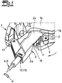
- Fig. 1
- das erfindungsgemäße Kraftfahrzeugtürschloss in einer perspektivischen Teilansicht,
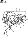
- Fig. 2
- den Gegenstand nach
Fig. 1 mit abgenommenen Anschlusselement und - Fig. 3
- das Anschlusselement in einer Rückansicht.
- Fig. 1
- the motor vehicle door lock according to the invention in a perspective partial view,
- Fig. 2
- the object after
Fig. 1 with removed connection element and - Fig. 3
- the connection element in a rear view.
In den Figuren ist ein Kraftfahrzeugtürschloss dargestellt, welches zunächst einmal über ein Schlossgehäuse 1, 2 verfügt. In dem Schlossgehäuse 1, 2 ist ein Betätigungshebel 3 angeordnet, der als Innenbetätigungshebel oder auch Außenbetätigungshebel bzw. Betätigungshaupthebel ausgebildet ist oder sein mag und insgesamt auf ein nicht näher dargestelltes Gesperre arbeitet. Insofern mag ein vergleichbarer Detailaufbau realisiert sein, wie er im Rahmen der gattungsbildenden
Neben dem Betätigungshebel 3 erkennt man ein Verbindungsmittel 4, 5, welches zur Kopplung des Betätigungshebels 3 mit einem außerhalb des Schlossgehäuses 1, 2 angeordneten Betätigungselement 6 dient. Bei dem Betätigungselement 6 handelt es sich um einen Außentürgriff, sofern der Betätigungshebel 3 als Außenbetätigungshebel ausgebildet ist. Alternativ kann es sich aber auch um einen Innentürgriff handeln, wenn der Betätigungshebel 3 einen Innenbetätigungshebel darstellt. Selbstverständlich sind auch Mischformen oder andere Ausgestaltungen denkbar und werden von der Erfindung umfasst.In addition to the
Darüber hinaus ist ein Anschlusselement 2 zur Lagerung des Verbindungsmittels 4, 5 am Schlossgehäuse 1, 2 vorgesehen. Das Anschlusselement 2 ist im Rahmen der Erfindung als mit einem Grundgehäuse 1 zum Schlossgehäuse 1, 2 vereinigbares Teilgehäuse 2 ausgebildet. Dieses Teilgehäuse 2 deckt in montiertem Zustand sowohl eine Öffnung 7 des Grundgehäuses 1 als auch einen Anbindungsbereich 8 des Betätigungshebels 3 an das Verbindungsmittel 4, 5 ab.In addition, a
Das heißt, das Anschlusselement 2 fungiert als Teilgehäuse 2 und definiert zusammen mit dem Grundgehäuse 1 insgesamt das Schlossgehäuse 1, 2. Zu diesem Zweck ist das Anschlusselement bzw. Teilgehäuse 2 regelmäßig werkstoffeinheitlich bzw. materialeinheitlich mit dem Grundgehäuse 1 ausgelegt. Das heißt, das Grundgehäuse 1 und auch das Anschlusselement bzw. Teilgehäuse 2 werden jeweils als Kunststoffspritzgussteil aus einem gleichen oder vergleichbaren Kunststoff hergestellt. Das ist selbstverständlich nur als bevorzugte Variante und nicht einschränkend zu verstehen.That is, the
Jedenfalls kommt dem Anschlusselement bzw. Teilgehäuse 2 eine zweifache Funktion zu. Zunächst einmal ist das Verbindungsmittel 4, 5 an dem Anschlusselement bzw. Teilgehäuse 2 gelagert. Darüber hinaus fungiert das Anschlusselement bzw. Teilgehäuse 2 als Bestandteil des Schlossgehäuses 1, 2 und definiert zusammen mit dem Grundgehäuse 1 das fragliche Schlossgehäuse 1, 2. Dabei ist das Anschlusselement bzw. Teilgehäuse 2 insgesamt lösbar mit dem Grundgehäuse 1 verbunden.In any case, the connection element or
Zu diesem Zweck erkennt man bei einer vergleichenden Betrachtung der
Ein Vergleich der
Mit der Lageraufnahme 12, 13 kann ein Befestigungsring 14, 15 am Verbindungsmittel 4, 5 lösbar gekoppelt werden. Tatsächlich setzt sich der Befestigungsring 14, 15 aus zwei Befestigungsflanschen 14 zusammen, die zwischen sich eine Befestigungsnut 15 einschließen. Sobald der Befestigungsring 14, 15 in die Lageraufnahme 12, 13 eingesteckt wird, tauchen der Schlitz 12 und die beidseitigen Stege 13 in die Befestigungsnut 15 ein. Die Befestigungsflansche 14 nehmen zusätzlich die Stege 13 zwischen sich auf. Auf diese Weise ist die Lageraufnahme 12, 13 insgesamt als Widerlager 12, 13 für den Befestigungsring 14, 15 und folglich das Verbindungsmittel 4, 5 im Ganzen ausgelegt.With the bearing
Das Anschlusselement 2 ist im Querschnitt L-förmig ausgebildet. Tatsächlich beobachtet man einen längeren L-Schenkel 2a und einen kürzeren L-Schenkel 2b. Bei dem längeren L-Schenkel 2a handelt es sich um eine Fortsetzungsoberfläche 2a, die mit einer Grundgehäuseoberfläche 1a insgesamt eine Oberfläche 1a, 2a des Schlossgehäuses 1, 2 definiert. Der kurze L-Schenkel 2b stellt dagegen eine Seitenfläche 2b dar und wirkt mit einer zugehörigen Seitenfläche 1b des Grundgehäuses 1 zusammen. Man erkennt, dass die Seitenfläche 2b des Anschlusselementes bzw. Teilgehäuses 2 insgesamt eine Ausnehmung bzw. Öffnung 16 aufweist, durch welche hindurch unverändert der Anbindungsbereich 8 - zumindest von der Seite her - zugänglich ist.The connecting
Die Fortsetzungsoberfläche 2a des Anschlusselementes 2 ist mit einem bzw. mehreren Formschlusselementen 17 ausgerüstet, die man am besten in der Rückansicht nach
Das Verbindungsmittel 4, 5 ist im Ausführungsbeispiel als Bowdenzug 4, 5 ausgebildet. Der Bowdenzug 4, 5 verfügt über eine Hülle 5 und eine Seele bzw. ein Seil 4. Die Hülle 5 weist den Befestigungsring 14, 15 auf. Da der Befestigungsring 14, 15 lösbar in der Lageraufnahme 12, 13 am Anschlusselement 2 aufgenommen wird, fungiert die Lageraufnahme 12, 13 als Widerlager 12,13 am Anschlusselement 2, und zwar primär für die Hülle 5 und folglich für den Bowdenzug 4, 5 im Ganzen. Zugleich sorgt das Anschlusselement 2 dafür, dass die Öffnung 7 im Grundgehäuse 1 und auch der Anbindungsbereich 8 größtenteils - bis auf die Öffnung 16 - abgedeckt werden. Dadurch wird ein maximaler Schutz vor äußeren Einflüssen zur Verfügung gestellt und zugleich gewährleistet, dass der Anbindungsbereich 8 nach wie vor zugänglich ist. Das ist für einen etwaigen Austausch des Verbindungsmittels 4, 5, im Ausführungsbeispiel des Bowdenzuges 4, 5, gegen beispielsweise eine an dieser Stelle ebenfalls mögliche Stange von besonderer Bedeutung.The connecting means 4, 5 is formed in the embodiment as a
Claims (8)
- A motor vehicle door lock, having: at least one operating lever (3), which is arranged in a lock housing (1, 2), a connecting means (4, 5) for coupling the operating lever (3) to an operating element (6) arranged outside the lock housing (1, 2), and an attachment element (2) for mounting the connecting means (4, 5) on the lock housing (1, 2), wherein the attachment element (2) is in the form of a part-housing (2), which can be combined with a main housing (1) to form the lock housing (1, 2) and at least largely covers an opening (7) in the main housing (1) and a joining region (8) of the operating lever (3) to the connecting means (4, 5) when in the mounted state,
wherein the attachment element (2) is connected detachably to the main housing (1),
characterised in that- to this end at least one plug pin (10) is provided, which engages in a plug socket (9), wherein- the plug socket (9) and the plug pin (10) that engages therein together define a rotation axis (D) for the attachment element (2) that can be pivoted onto the main housing (1). - The motor vehicle door lock according to Claim 1, characterised in that the attachment element (2) is equipped with a bearing holder (12, 13) for a fastening ring (14, 15) of the connecting means (4, 5).
- The motor vehicle door lock according to Claim 2, characterised in that the bearing holder (12, 13) is in the form of a slotted holder (12, 13).
- The motor vehicle door lock according to any one of Claims 2 to 3, characterised in that the fastening ring (14, 15) is equipped with two fastening flanges (14), which enclose a fastening groove (15) between them.
- The motor vehicle door lock according to any one of Claims 2 to 4, characterised in that the bearing holder (12, 13) is designed as a counter bearing (12, 13) for the fastening ring (14, 15) and therefore for the connecting means (4, 5) as a whole.
- The motor vehicle door lock according to any one of Claims 1 to 5, characterised in that the attachment element (2) has an L-shaped cross section.
- The motor vehicle door lock according to Claim 6, characterised in that one L limb (2a) is formed as a continuation surface (2a) of a main housing surface (1a).
- The motor vehicle door lock according to Claim 7, characterised in that the continuation surface (2a) is equipped with one or more form-fitting elements (17), which correspond to counter form-fitting elements (18) on the main housing surface (1 a).
Applications Claiming Priority (2)
| Application Number | Priority Date | Filing Date | Title |
|---|---|---|---|
| DE201110120882 DE102011120882A1 (en) | 2011-12-09 | 2011-12-09 | Motor vehicle door lock |
| PCT/DE2012/001180 WO2013083116A2 (en) | 2011-12-09 | 2012-12-06 | Motor vehicle door lock |
Publications (2)
| Publication Number | Publication Date |
|---|---|
| EP2788567A2 EP2788567A2 (en) | 2014-10-15 |
| EP2788567B1 true EP2788567B1 (en) | 2016-05-11 |
Family
ID=48013679
Family Applications (1)
| Application Number | Title | Priority Date | Filing Date |
|---|---|---|---|
| EP12837631.6A Active EP2788567B1 (en) | 2011-12-09 | 2012-12-06 | Motor vehicle door lock |
Country Status (11)
| Country | Link |
|---|---|
| US (1) | US9540854B2 (en) |
| EP (1) | EP2788567B1 (en) |
| JP (1) | JP6094009B2 (en) |
| KR (1) | KR101970852B1 (en) |
| CN (1) | CN104040099B (en) |
| BR (1) | BR112014013537A2 (en) |
| CA (1) | CA2857708A1 (en) |
| DE (1) | DE102011120882A1 (en) |
| MX (1) | MX2014006771A (en) |
| RU (1) | RU2621658C2 (en) |
| WO (1) | WO2013083116A2 (en) |
Families Citing this family (14)
| Publication number | Priority date | Publication date | Assignee | Title |
|---|---|---|---|---|
| DE102013203166B4 (en) * | 2013-02-26 | 2020-01-30 | Kiekert Ag | Bowden |
| DE102013009225A1 (en) * | 2013-05-31 | 2014-12-04 | Kiekert Aktiengesellschaft | Bowden cable bearing for a motor vehicle lock |
| JP6187014B2 (en) * | 2013-08-09 | 2017-08-30 | アイシン精機株式会社 | Vehicle door lock device |
| JP6368951B2 (en) * | 2014-03-13 | 2018-08-08 | 三井金属アクト株式会社 | Vehicle door latch device |
| DE102014221861A1 (en) * | 2014-10-27 | 2016-04-28 | Bayerische Motoren Werke Aktiengesellschaft | Locking device and method for assembling a lock device |
| DE102015004766A1 (en) * | 2015-04-16 | 2016-10-20 | Klekert Aktiengesellschaft | Bowden cable connection for a motor vehicle lock |
| CN106285242B (en) * | 2015-06-01 | 2019-04-02 | 开开特股份公司 | Brake cable as the actuator of functional unit in motor vehicle |
| JP6649052B2 (en) * | 2015-11-18 | 2020-02-19 | 株式会社ユーシン | Door lock device |
| CN107227906B (en) * | 2016-03-25 | 2021-01-29 | 开开特股份公司 | Motor vehicle lock with cover |
| JP6825302B2 (en) * | 2016-10-26 | 2021-02-03 | アイシン精機株式会社 | Vehicle door device |
| DE102017115895A1 (en) * | 2017-07-14 | 2019-01-17 | Huf Hülsbeck & Fürst Gmbh & Co. Kg | Motor vehicle lock arrangement |
| US11136794B2 (en) | 2018-01-15 | 2021-10-05 | Kiekert Ag | Transmission means for a motor vehicle latch and a motor vehicle latch |
| CN207960257U (en) | 2018-02-22 | 2018-10-12 | 开开特股份公司 | Automotive lock |
| DE102019215589A1 (en) * | 2019-10-10 | 2021-04-15 | Volkswagen Aktiengesellschaft | Lock device for a vehicle door, lock arrangement |
Family Cites Families (32)
| Publication number | Priority date | Publication date | Assignee | Title |
|---|---|---|---|---|
| US4945784A (en) * | 1984-07-02 | 1990-08-07 | General Motors Corporation | Cable connector assembly |
| US4929007A (en) * | 1987-03-30 | 1990-05-29 | Magna International Inc. | Latch mechanism |
| US5181166A (en) * | 1991-05-31 | 1993-01-19 | Schlumberger Canada Limited | Securing mechanism for an electricity metering device |
| JPH0571377A (en) | 1991-09-09 | 1993-03-23 | Hitachi Ltd | Air flow rate measuring device |
| JP2573895B2 (en) * | 1992-01-31 | 1997-01-22 | 株式会社大井製作所 | Door lock device for automobile |
| JP2528945Y2 (en) * | 1992-02-28 | 1997-03-12 | 株式会社大井製作所 | Door lock device for automobile |
| FR2786522B1 (en) * | 1998-11-26 | 2001-06-08 | Valeo Securite Habitacle | LOCK FOR MOTOR VEHICLE DOOR |
| DE10164021B4 (en) * | 2001-12-28 | 2014-05-15 | Volkswagen Ag | Closing device for a front flap of a motor vehicle |
| JP4085302B2 (en) * | 2002-01-16 | 2008-05-14 | アイシン精機株式会社 | Door lock device |
| JP2003314116A (en) * | 2002-04-19 | 2003-11-06 | Aisin Seiki Co Ltd | Door lock device for car |
| JP4050609B2 (en) * | 2002-12-24 | 2008-02-20 | 三井金属鉱業株式会社 | Door latch device |
| DE20316352U1 (en) | 2003-03-10 | 2004-01-15 | Intier Automotive Closures Inc., Newmarket | Lock for a door of a motor vehicle comprises an actuating device and connecting devices that are encapsulated on the outside |
| DE10334223B4 (en) | 2003-07-26 | 2007-07-12 | Daimlerchrysler Ag | Lock housing for a motor vehicle door lock |
| DE102004002755A1 (en) * | 2004-01-20 | 2005-08-11 | Daimlerchrysler Ag | Vehicle lock with separate actuators for internal or external operation has identical bearings fitted to form either guide bearings for actuating rods or abutments for Bowden cable actuators |
| FR2877632B1 (en) * | 2004-11-08 | 2007-01-12 | Peugeot Citroen Automobiles Sa | DEVICE FOR PROHIBITING THE UNAUTHORIZED MANEUVERING OF THE COVER LOCKING CABLE OF A MOTOR VEHICLE |
| US7815231B2 (en) * | 2004-11-17 | 2010-10-19 | Aisin Seiki Kabushiki Kaisha | Door lock device for automotive |
| JP2006233506A (en) * | 2005-02-23 | 2006-09-07 | Aisin Seiki Co Ltd | Door lock device |
| DE602006007894D1 (en) * | 2005-02-23 | 2009-09-03 | Aisin Seiki | Locks |
| CN102691447B (en) * | 2005-03-23 | 2014-09-24 | 马格纳·克劳祖雷斯有限公司 | Global side door latch |
| FR2923249B1 (en) * | 2007-11-07 | 2013-02-08 | Valeo Securite Habitacle | ARRANGEMENT FOR MOUNTING A CARDAN SEAL FOR CONNECTING THE BARREL OF A LATCH TO A LOCK |
| US20100072761A1 (en) * | 2008-02-04 | 2010-03-25 | Kris Tomaszewski | Global Side Door Latch |
| US20100095802A1 (en) * | 2008-10-21 | 2010-04-22 | Patel Rajesh K | Error-proofed door handle cable end-fitting |
| JP4802347B2 (en) * | 2009-07-16 | 2011-10-26 | 三井金属アクト株式会社 | Control device for vehicle door latch |
| DE102009056921A1 (en) * | 2009-12-03 | 2011-06-09 | GM Global Technology Operations LLC, ( n. d. Ges. d. Staates Delaware ), Detroit | Handle module for a motor vehicle door |
| JP4963720B2 (en) * | 2009-12-21 | 2012-06-27 | 三井金属アクト株式会社 | Actuator in vehicle door latch device |
| DE102011010175A1 (en) * | 2011-02-02 | 2012-08-02 | Kiekert Ag | Motor vehicle lock and manufacturing process |
| FR2984938B1 (en) * | 2011-12-21 | 2017-03-10 | Valeo Securite Habitacle | LOCK FOR MOTOR VEHICLE |
| US9022438B2 (en) * | 2012-09-14 | 2015-05-05 | Honda Motor Co., Ltd. | Cap assembly for vehicle |
| JP5966813B2 (en) * | 2012-09-24 | 2016-08-10 | アイシン精機株式会社 | Vehicle door lock device |
| JP5509377B1 (en) * | 2013-08-09 | 2014-06-04 | アイシン精機株式会社 | Vehicle door lock device |
| JP6368951B2 (en) * | 2014-03-13 | 2018-08-08 | 三井金属アクト株式会社 | Vehicle door latch device |
| DE202014102033U1 (en) * | 2014-04-30 | 2015-07-31 | BROSE SCHLIEßSYSTEME GMBH & CO. KG | Bowden |
-
2011
- 2011-12-09 DE DE201110120882 patent/DE102011120882A1/en not_active Withdrawn
-
2012
- 2012-12-06 CA CA2857708A patent/CA2857708A1/en not_active Abandoned
- 2012-12-06 US US14/363,866 patent/US9540854B2/en active Active
- 2012-12-06 JP JP2014545098A patent/JP6094009B2/en active Active
- 2012-12-06 MX MX2014006771A patent/MX2014006771A/en not_active Application Discontinuation
- 2012-12-06 CN CN201280060610.XA patent/CN104040099B/en active Active
- 2012-12-06 EP EP12837631.6A patent/EP2788567B1/en active Active
- 2012-12-06 BR BR112014013537A patent/BR112014013537A2/en not_active Application Discontinuation
- 2012-12-06 KR KR1020147015875A patent/KR101970852B1/en active IP Right Grant
- 2012-12-06 RU RU2014121742A patent/RU2621658C2/en not_active IP Right Cessation
- 2012-12-06 WO PCT/DE2012/001180 patent/WO2013083116A2/en active Application Filing
Also Published As
| Publication number | Publication date |
|---|---|
| CA2857708A1 (en) | 2013-06-13 |
| RU2014121742A (en) | 2016-01-27 |
| CN104040099A (en) | 2014-09-10 |
| WO2013083116A2 (en) | 2013-06-13 |
| EP2788567A2 (en) | 2014-10-15 |
| US20140333076A1 (en) | 2014-11-13 |
| CN104040099B (en) | 2016-04-13 |
| DE102011120882A1 (en) | 2013-06-13 |
| KR101970852B1 (en) | 2019-04-19 |
| RU2621658C2 (en) | 2017-06-06 |
| KR20140106557A (en) | 2014-09-03 |
| JP2015503042A (en) | 2015-01-29 |
| BR112014013537A2 (en) | 2017-06-13 |
| JP6094009B2 (en) | 2017-03-15 |
| WO2013083116A3 (en) | 2013-08-15 |
| MX2014006771A (en) | 2014-08-01 |
| US9540854B2 (en) | 2017-01-10 |
Similar Documents
| Publication | Publication Date | Title |
|---|---|---|
| EP2788567B1 (en) | Motor vehicle door lock | |
| EP3037683B1 (en) | Auxiliary locking drive for a motor vehicle lock | |
| EP2820207B1 (en) | Motor vehicle door lock | |
| DE10144166B4 (en) | Lock for a motor vehicle door | |
| DE102013108224A1 (en) | Motor vehicle door | |
| DE19955693C2 (en) | Motor vehicle door lock | |
| EP3994324B1 (en) | Motor vehicle door lock | |
| DE102019116201A1 (en) | Lever assembly for automotive applications | |
| EP3179021A1 (en) | Door handle assembly for a motor vehicle | |
| DE202006011218U1 (en) | emergency release | |
| EP2247810B1 (en) | Door lock for a motor vehicle | |
| DE2949281C2 (en) | Operating device for a door lock, in particular an internal operating device for a motor vehicle door lock | |
| DE102017116544B3 (en) | Glove box | |
| EP1612349B1 (en) | Locking device for a vehicle door lock | |
| EP2499315B1 (en) | Motor vehicle door latch | |
| DE102014116885A1 (en) | Motor vehicle door lock | |
| EP3078793A1 (en) | Exterior door handle for a motor vehicle | |
| DE102017125472A1 (en) | Motor vehicle lock | |
| EP2588691B1 (en) | Motor vehicle door lock | |
| DE202009005364U1 (en) | Swivel lever lock with a mechanically and electrically operated closure for the handle lever | |
| DE102017124523A1 (en) | Motor vehicle door lock | |
| DE102023123901A1 (en) | ACTUATOR AND TANK CONNECTION OR CHARGING CONNECTOR FLAW ASSEMBLY | |
| DE202007000312U1 (en) | Motor vehicle door lock has actuating element which converts rotational movement into basically linear movement, or vice versa, wherein actuating element has body upon which is located at least one actuating vane | |
| DE102023100626A1 (en) | ACTIVATION ARRANGEMENT AND FUEL FILLING OR. CHARGING ENTRANCE DOOR ASSEMBLY | |
| DE102022107657A1 (en) | Motor vehicle lock operating unit |
Legal Events
| Date | Code | Title | Description |
|---|---|---|---|
| PUAI | Public reference made under article 153(3) epc to a published international application that has entered the european phase |
Free format text: ORIGINAL CODE: 0009012 |
|
| 17P | Request for examination filed |
Effective date: 20140605 |
|
| AK | Designated contracting states |
Kind code of ref document: A2 Designated state(s): AL AT BE BG CH CY CZ DE DK EE ES FI FR GB GR HR HU IE IS IT LI LT LU LV MC MK MT NL NO PL PT RO RS SE SI SK SM TR |
|
| DAX | Request for extension of the european patent (deleted) | ||
| REG | Reference to a national code |
Ref country code: DE Ref legal event code: R079 Ref document number: 502012007086 Country of ref document: DE Free format text: PREVIOUS MAIN CLASS: E05B0065120000 Ipc: E05B0085020000 |
|
| RIC1 | Information provided on ipc code assigned before grant |
Ipc: E05B 77/34 20140101ALI20150915BHEP Ipc: E05B 85/02 20140101AFI20150915BHEP |
|
| GRAP | Despatch of communication of intention to grant a patent |
Free format text: ORIGINAL CODE: EPIDOSNIGR1 |
|
| INTG | Intention to grant announced |
Effective date: 20160105 |
|
| GRAS | Grant fee paid |
Free format text: ORIGINAL CODE: EPIDOSNIGR3 |
|
| GRAA | (expected) grant |
Free format text: ORIGINAL CODE: 0009210 |
|
| AK | Designated contracting states |
Kind code of ref document: B1 Designated state(s): AL AT BE BG CH CY CZ DE DK EE ES FI FR GB GR HR HU IE IS IT LI LT LU LV MC MK MT NL NO PL PT RO RS SE SI SK SM TR |
|
| REG | Reference to a national code |
Ref country code: GB Ref legal event code: FG4D Free format text: NOT ENGLISH |
|
| REG | Reference to a national code |
Ref country code: CH Ref legal event code: EP |
|
| REG | Reference to a national code |
Ref country code: AT Ref legal event code: REF Ref document number: 798822 Country of ref document: AT Kind code of ref document: T Effective date: 20160515 |
|
| REG | Reference to a national code |
Ref country code: IE Ref legal event code: FG4D Free format text: LANGUAGE OF EP DOCUMENT: GERMAN |
|
| REG | Reference to a national code |
Ref country code: DE Ref legal event code: R096 Ref document number: 502012007086 Country of ref document: DE |
|
| REG | Reference to a national code |
Ref country code: LT Ref legal event code: MG4D |
|
| REG | Reference to a national code |
Ref country code: NL Ref legal event code: MP Effective date: 20160511 |
|
| PG25 | Lapsed in a contracting state [announced via postgrant information from national office to epo] |
Ref country code: NO Free format text: LAPSE BECAUSE OF FAILURE TO SUBMIT A TRANSLATION OF THE DESCRIPTION OR TO PAY THE FEE WITHIN THE PRESCRIBED TIME-LIMIT Effective date: 20160811 Ref country code: LT Free format text: LAPSE BECAUSE OF FAILURE TO SUBMIT A TRANSLATION OF THE DESCRIPTION OR TO PAY THE FEE WITHIN THE PRESCRIBED TIME-LIMIT Effective date: 20160511 Ref country code: NL Free format text: LAPSE BECAUSE OF FAILURE TO SUBMIT A TRANSLATION OF THE DESCRIPTION OR TO PAY THE FEE WITHIN THE PRESCRIBED TIME-LIMIT Effective date: 20160511 Ref country code: FI Free format text: LAPSE BECAUSE OF FAILURE TO SUBMIT A TRANSLATION OF THE DESCRIPTION OR TO PAY THE FEE WITHIN THE PRESCRIBED TIME-LIMIT Effective date: 20160511 |
|
| PG25 | Lapsed in a contracting state [announced via postgrant information from national office to epo] |
Ref country code: HR Free format text: LAPSE BECAUSE OF FAILURE TO SUBMIT A TRANSLATION OF THE DESCRIPTION OR TO PAY THE FEE WITHIN THE PRESCRIBED TIME-LIMIT Effective date: 20160511 Ref country code: PT Free format text: LAPSE BECAUSE OF FAILURE TO SUBMIT A TRANSLATION OF THE DESCRIPTION OR TO PAY THE FEE WITHIN THE PRESCRIBED TIME-LIMIT Effective date: 20160912 Ref country code: SE Free format text: LAPSE BECAUSE OF FAILURE TO SUBMIT A TRANSLATION OF THE DESCRIPTION OR TO PAY THE FEE WITHIN THE PRESCRIBED TIME-LIMIT Effective date: 20160511 Ref country code: GR Free format text: LAPSE BECAUSE OF FAILURE TO SUBMIT A TRANSLATION OF THE DESCRIPTION OR TO PAY THE FEE WITHIN THE PRESCRIBED TIME-LIMIT Effective date: 20160812 Ref country code: LV Free format text: LAPSE BECAUSE OF FAILURE TO SUBMIT A TRANSLATION OF THE DESCRIPTION OR TO PAY THE FEE WITHIN THE PRESCRIBED TIME-LIMIT Effective date: 20160511 Ref country code: RS Free format text: LAPSE BECAUSE OF FAILURE TO SUBMIT A TRANSLATION OF THE DESCRIPTION OR TO PAY THE FEE WITHIN THE PRESCRIBED TIME-LIMIT Effective date: 20160511 Ref country code: ES Free format text: LAPSE BECAUSE OF FAILURE TO SUBMIT A TRANSLATION OF THE DESCRIPTION OR TO PAY THE FEE WITHIN THE PRESCRIBED TIME-LIMIT Effective date: 20160511 |
|
| REG | Reference to a national code |
Ref country code: FR Ref legal event code: PLFP Year of fee payment: 5 |
|
| PG25 | Lapsed in a contracting state [announced via postgrant information from national office to epo] |
Ref country code: IT Free format text: LAPSE BECAUSE OF FAILURE TO SUBMIT A TRANSLATION OF THE DESCRIPTION OR TO PAY THE FEE WITHIN THE PRESCRIBED TIME-LIMIT Effective date: 20160511 |
|
| PG25 | Lapsed in a contracting state [announced via postgrant information from national office to epo] |
Ref country code: RO Free format text: LAPSE BECAUSE OF FAILURE TO SUBMIT A TRANSLATION OF THE DESCRIPTION OR TO PAY THE FEE WITHIN THE PRESCRIBED TIME-LIMIT Effective date: 20160511 Ref country code: SK Free format text: LAPSE BECAUSE OF FAILURE TO SUBMIT A TRANSLATION OF THE DESCRIPTION OR TO PAY THE FEE WITHIN THE PRESCRIBED TIME-LIMIT Effective date: 20160511 Ref country code: DK Free format text: LAPSE BECAUSE OF FAILURE TO SUBMIT A TRANSLATION OF THE DESCRIPTION OR TO PAY THE FEE WITHIN THE PRESCRIBED TIME-LIMIT Effective date: 20160511 Ref country code: EE Free format text: LAPSE BECAUSE OF FAILURE TO SUBMIT A TRANSLATION OF THE DESCRIPTION OR TO PAY THE FEE WITHIN THE PRESCRIBED TIME-LIMIT Effective date: 20160511 |
|
| REG | Reference to a national code |
Ref country code: DE Ref legal event code: R097 Ref document number: 502012007086 Country of ref document: DE |
|
| PG25 | Lapsed in a contracting state [announced via postgrant information from national office to epo] |
Ref country code: PL Free format text: LAPSE BECAUSE OF FAILURE TO SUBMIT A TRANSLATION OF THE DESCRIPTION OR TO PAY THE FEE WITHIN THE PRESCRIBED TIME-LIMIT Effective date: 20160511 Ref country code: SM Free format text: LAPSE BECAUSE OF FAILURE TO SUBMIT A TRANSLATION OF THE DESCRIPTION OR TO PAY THE FEE WITHIN THE PRESCRIBED TIME-LIMIT Effective date: 20160511 |
|
| PLBE | No opposition filed within time limit |
Free format text: ORIGINAL CODE: 0009261 |
|
| STAA | Information on the status of an ep patent application or granted ep patent |
Free format text: STATUS: NO OPPOSITION FILED WITHIN TIME LIMIT |
|
| 26N | No opposition filed |
Effective date: 20170214 |
|
| PG25 | Lapsed in a contracting state [announced via postgrant information from national office to epo] |
Ref country code: BE Free format text: LAPSE BECAUSE OF NON-PAYMENT OF DUE FEES Effective date: 20161231 Ref country code: SI Free format text: LAPSE BECAUSE OF FAILURE TO SUBMIT A TRANSLATION OF THE DESCRIPTION OR TO PAY THE FEE WITHIN THE PRESCRIBED TIME-LIMIT Effective date: 20160511 |
|
| PG25 | Lapsed in a contracting state [announced via postgrant information from national office to epo] |
Ref country code: MC Free format text: LAPSE BECAUSE OF FAILURE TO SUBMIT A TRANSLATION OF THE DESCRIPTION OR TO PAY THE FEE WITHIN THE PRESCRIBED TIME-LIMIT Effective date: 20160511 |
|
| REG | Reference to a national code |
Ref country code: CH Ref legal event code: PL |
|
| GBPC | Gb: european patent ceased through non-payment of renewal fee |
Effective date: 20161206 |
|
| REG | Reference to a national code |
Ref country code: IE Ref legal event code: MM4A |
|
| PG25 | Lapsed in a contracting state [announced via postgrant information from national office to epo] |
Ref country code: CH Free format text: LAPSE BECAUSE OF NON-PAYMENT OF DUE FEES Effective date: 20161231 Ref country code: LU Free format text: LAPSE BECAUSE OF NON-PAYMENT OF DUE FEES Effective date: 20161206 Ref country code: LI Free format text: LAPSE BECAUSE OF NON-PAYMENT OF DUE FEES Effective date: 20161231 |
|
| PG25 | Lapsed in a contracting state [announced via postgrant information from national office to epo] |
Ref country code: GB Free format text: LAPSE BECAUSE OF NON-PAYMENT OF DUE FEES Effective date: 20161206 Ref country code: IE Free format text: LAPSE BECAUSE OF NON-PAYMENT OF DUE FEES Effective date: 20161206 |
|
| REG | Reference to a national code |
Ref country code: FR Ref legal event code: PLFP Year of fee payment: 6 |
|
| REG | Reference to a national code |
Ref country code: BE Ref legal event code: MM Effective date: 20161231 |
|
| PG25 | Lapsed in a contracting state [announced via postgrant information from national office to epo] |
Ref country code: HU Free format text: LAPSE BECAUSE OF FAILURE TO SUBMIT A TRANSLATION OF THE DESCRIPTION OR TO PAY THE FEE WITHIN THE PRESCRIBED TIME-LIMIT; INVALID AB INITIO Effective date: 20121206 |
|
| PG25 | Lapsed in a contracting state [announced via postgrant information from national office to epo] |
Ref country code: MK Free format text: LAPSE BECAUSE OF FAILURE TO SUBMIT A TRANSLATION OF THE DESCRIPTION OR TO PAY THE FEE WITHIN THE PRESCRIBED TIME-LIMIT Effective date: 20160511 Ref country code: CY Free format text: LAPSE BECAUSE OF FAILURE TO SUBMIT A TRANSLATION OF THE DESCRIPTION OR TO PAY THE FEE WITHIN THE PRESCRIBED TIME-LIMIT Effective date: 20160511 Ref country code: IS Free format text: LAPSE BECAUSE OF FAILURE TO SUBMIT A TRANSLATION OF THE DESCRIPTION OR TO PAY THE FEE WITHIN THE PRESCRIBED TIME-LIMIT Effective date: 20160511 |
|
| PG25 | Lapsed in a contracting state [announced via postgrant information from national office to epo] |
Ref country code: BG Free format text: LAPSE BECAUSE OF FAILURE TO SUBMIT A TRANSLATION OF THE DESCRIPTION OR TO PAY THE FEE WITHIN THE PRESCRIBED TIME-LIMIT Effective date: 20160511 |
|
| PG25 | Lapsed in a contracting state [announced via postgrant information from national office to epo] |
Ref country code: MT Free format text: LAPSE BECAUSE OF FAILURE TO SUBMIT A TRANSLATION OF THE DESCRIPTION OR TO PAY THE FEE WITHIN THE PRESCRIBED TIME-LIMIT Effective date: 20160511 |
|
| PG25 | Lapsed in a contracting state [announced via postgrant information from national office to epo] |
Ref country code: TR Free format text: LAPSE BECAUSE OF FAILURE TO SUBMIT A TRANSLATION OF THE DESCRIPTION OR TO PAY THE FEE WITHIN THE PRESCRIBED TIME-LIMIT Effective date: 20160511 Ref country code: AL Free format text: LAPSE BECAUSE OF FAILURE TO SUBMIT A TRANSLATION OF THE DESCRIPTION OR TO PAY THE FEE WITHIN THE PRESCRIBED TIME-LIMIT Effective date: 20160511 |
|
| REG | Reference to a national code |
Ref country code: AT Ref legal event code: MM01 Ref document number: 798822 Country of ref document: AT Kind code of ref document: T Effective date: 20171206 |
|
| PG25 | Lapsed in a contracting state [announced via postgrant information from national office to epo] |
Ref country code: AT Free format text: LAPSE BECAUSE OF NON-PAYMENT OF DUE FEES Effective date: 20171206 |
|
| P01 | Opt-out of the competence of the unified patent court (upc) registered |
Effective date: 20230529 |
|
| PGFP | Annual fee paid to national office [announced via postgrant information from national office to epo] |
Ref country code: FR Payment date: 20231219 Year of fee payment: 12 Ref country code: DE Payment date: 20231214 Year of fee payment: 12 Ref country code: CZ Payment date: 20231127 Year of fee payment: 12 |